EP1048367B1 - Verfahren zum Walzen von Draht und Walzwerk - Google Patents
Verfahren zum Walzen von Draht und Walzwerk Download PDFInfo
- Publication number
- EP1048367B1 EP1048367B1 EP00303156A EP00303156A EP1048367B1 EP 1048367 B1 EP1048367 B1 EP 1048367B1 EP 00303156 A EP00303156 A EP 00303156A EP 00303156 A EP00303156 A EP 00303156A EP 1048367 B1 EP1048367 B1 EP 1048367B1
- Authority
- EP
- European Patent Office
- Prior art keywords
- mill
- rollers
- rolling
- block
- mbm
- Prior art date
- Legal status (The legal status is an assumption and is not a legal conclusion. Google has not performed a legal analysis and makes no representation as to the accuracy of the status listed.)
- Expired - Lifetime
Links
Images


Classifications
-
- B—PERFORMING OPERATIONS; TRANSPORTING
- B21—MECHANICAL METAL-WORKING WITHOUT ESSENTIALLY REMOVING MATERIAL; PUNCHING METAL
- B21B—ROLLING OF METAL
- B21B1/00—Metal-rolling methods or mills for making semi-finished products of solid or profiled cross-section; Sequence of operations in milling trains; Layout of rolling-mill plant, e.g. grouping of stands; Succession of passes or of sectional pass alternations
- B21B1/16—Metal-rolling methods or mills for making semi-finished products of solid or profiled cross-section; Sequence of operations in milling trains; Layout of rolling-mill plant, e.g. grouping of stands; Succession of passes or of sectional pass alternations for rolling wire rods, bars, merchant bars, rounds wire or material of like small cross-section
- B21B1/18—Metal-rolling methods or mills for making semi-finished products of solid or profiled cross-section; Sequence of operations in milling trains; Layout of rolling-mill plant, e.g. grouping of stands; Succession of passes or of sectional pass alternations for rolling wire rods, bars, merchant bars, rounds wire or material of like small cross-section in a continuous process
Definitions
- the present invention relates, according to the preambles of method claim 1 and apparatus claim 2, to improvements in rolling metal rods, particularly, steel rods, to produce steel wire (see e.g. JP07096301 A). According to the present invention it is possible to produce wires of various diameters starting from a rod of one diameter without changing rollers.
- a round rod of diameter 20.5mm is used as the starting material from the rough intermediate line.
- the rolled material is passed to the sizing mill so that it may be rolled by both the front group and the rear group (7.0mm), by only the front group (7.5mm), or by only the front group of changed rollers.
- the rolling also starts from the round rod material of diameter 20.5mm (also Figure 3).
- the material is rolled by a part (F1-F4) of the block mill having the second group of rollers to diameter 13.5mm.
- the rollers of F5 and F6 stands are removed and replaced with a dummy guide.
- the rolled material of diameter 13.5mm is passed to the sizing mill, and rolled by both the front group and the rear group of the rollers (11.0mm), or by only the front group (12.0mm).
- Wires in the thickness range of "very bold" are produced, also starting from the round rod material of diameter 20.5mm, by not using the block mill but directly using the sizing mill. Both the front and the rear groups of the rollers are used (17.0mm), only the front group is used (19.0mm) or both the front and the rear groups with changed rollers are used (18.0mm).
- the object of the present invention is to solve the above discussed problems relating to wire rolling, and to provide a method of rolling which enables production of wire products having various diameters from a round rod of one diameter without changing of block mill rollers, which is a lengthy and laborious process.
- the invention also provides a rolling mill for carrying out the rolling method.
- a method of rolling wire rods having selected final diameters from a rod of a single diameter supplied from a roughing mill along a pass line wherein the mill includes an intermediate block mill for receiving rod from the roughing mill, the block mill having rollers arranged in a front group and a rear group, each of which can be dummied, a mini block mill for receiving rod from the block mill which is shuntable from the pass line and a sizing mill for receiving rod from the mini block mill, the sizing mill having plural sets of rollers, at least one of which sets is shuntable from the pass line, said method comprising selecting combinations of the block mill roller groups, mini block mill and sizing roller sets and rolling rod through the selected combination so as to produce a wire rod having a desired final calibre.
- a rolling mill for rolling wire rod having selected final diameters from a single diameter supplied from a roughing mill along a pass line
- said rolling mill comprising an intermediate block mill for receiving rod from a roughing mill, the block mill having a front group of rollers and a rear group, each of which can be independently dummied, a mini block mill for receiving rod from the block mill which can be shunted between an operative position on the pass line and a non-operative position away from the pass line and a sizing mill comprising at least two sets of rollers, at least one of which sets is capable of being shunted between an operative position on the pass line and a non-operative position away from the pass line, the rollers of the block mill, mini block mill and sizing mill being selectable in various combinations to produce wire rod of desired calibre from a single diameter wire rod supplied by the roughing mill.
- the method of rolling according to the present invention which achieves the above object is a method of wire rolling of metal rods supplied from rough rolling step by intermediate rolling with a block mill and finish rolling with a sizing mill to form wire products.
- the method uses a rolling mill, which comprises, as illustrated in Figure 5, a block mill (BM), a sizing mill (SM) and a mini block mill (MBM) installed between the BM and the SM as a reducer.
- Rollers of the block mill (BM) are divided into two groups, the front group and the rear group, so as to make it possible either to use both the front and the rear groups, to use only the front group by dummy passing the rear group, or to use no block mill (BM) by by-passing the material to be rolled through another guide.
- the mini block mill (MBM) is shuntable from the pass line.
- the sizing mill (SM) consists of plural sets of rollers, and at least one of the sets is shuntable from the pass line. Combinations of use and non-use of the rollers can be chosen so that it may be possible to produce wires of different diameters from a material round rod of one diameter.
- the rolling mill for carrying out the above described method of rolling is the rolling mill for wire rolling of metal rods supplied from rough rolling step by intermediate rolling with a block mill and finish rolling with a sizing mill to form wire products.
- the rolling mill comprises, as illustrated in Figure 5, a block mill (BM), a sizing mill (SM) and a mini block mill (MBM) installed between the block mill and the sizing mill as a reducer.
- Rollers of the block mill (BM) are divided into two groups, the front group and the rear group (BM1 and BM2), so as to make it possible either to use both the front and the rear groups or only the front group by passing the rear group with a dummy pass (DP1); and a guide or guides for by-passing (BP) the material to be rolled.
- DP1 and BM2 dummy pass
- BP guide or guides for by-passing
- the mill also has another dummy pass (DP2), and thus, the mini block mill is shuntable from the pass line.
- the sizing mill consists of plural sets of rollers, and at least one of the sets is shuntable from the pass line. Combinations of use and non-use of the rollers can be chosen so as to make it possible to produce wires of different diameters from a material round rod of one diameter.
- the by-passes for the rollers can be provided by installing guides to pass the rolled wires or the material wires to be rolled in suitable positions in close vicinity to the centre of the rolling line without interference to the rollers or to changing the rollers.
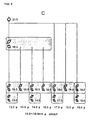
- the rolling mill combinations shown diagrammatically in Figure 6 show, for example, the sequences employed in cases 1 to 6 in Table 1.
- case 1 all rollers in the two groups of the block mill BM1 and BM2 are employed.
- the mini block mill (MBM) is operational and all sets of rollers of the sizing mill (SM1 and SM2) are in use.
- Case 2 is the same as case 1 except that the final sizing mill set (SM2) is dummied by shifting the set (SM2) from the pass line.
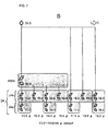
- Case 3 is achieved by employing different roll sets (SM1(c) & SM1(d)) on the sizing mills and dummying the MBM.
- Case 4 is the same as case 3 except that the second set of sizing rolls (SM2) are dummied.
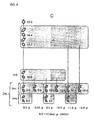
- case 5 the MBM remains dummied and different rolls (SM1(f) & SM2(g)) are employed as the sizing mills.
- Case 6 is the same as case 5 except that the second set of sizing rolls (SM2) are dummied.
- Figures 7 and 8 show other combinations for rolling specific calibre wire rod which are also listed in Tables 1 and 2.
Landscapes
- Engineering & Computer Science (AREA)
- Mechanical Engineering (AREA)
- Metal Rolling (AREA)
- Reduction Rolling/Reduction Stand/Operation Of Reduction Machine (AREA)
- Control Of Metal Rolling (AREA)
Claims (2)
- Ein Verfahren zum Walzen von Walzdrähten, welche ausgewählte Enddurchmesser aufweisen, aus einer Stange mit einem einzigen Durchmesser, die aus einem Grobwalzwerk zugeführt wird, entlang einer Walzbahn, wobei das Walzwerk ein Zwischenblockwalzwerk BM zum Aufnehmen der Stange aus dem Grobwalzwerk aufweist, das Blockwalzwerk BM Walzen aufweist, die in einer vorderen Gruppe BM1 und einer hinteren Gruppe BM2 angeordnet sind, dadurch gekennzeichnet, dass jede der gesagten vorderen und hinteren Gruppe blind gesetzt werden kann, das Walzwerk ferner ein Miniblockwalzwerk MBM zum Aufnehmen der Stange aus dem Blockwalzwerk BM umfasst, welches aus der Walzbahn herausnehmbar ist, und ferner ein Maßwalzwerk SM zum Aufnehmen der Stange aus dem Miniblockwalzwerk MBM, wobei das Maßwalzwerk eine Vielzahl von Walzensätzen SM1, 2 aufweist, von denen wenigstens ein Satz aus der Walzbahn herausnehmbar ist, wobei das gesagte Verfahren das Auswählen von Kombinationen der Blockwalzwerkwalzengruppen BM1, 2 des Miniblockwalzwerks MBM und der Maßwalzensätze SM1, 2 umfasst, und ferner das Walzen der Stange durch die ausgewählte Kombination, so dass ein Walzdraht hergestellt wird, der ein gewünschtes Endkaliber aufweist.
- Ein Walzwerk für Walzdraht, welcher ausgewählte Enddurchmesser aufweist, aus einem einzigen Durchmesser, der aus einem Grobwalzwerk zugeführt wird, entlang einer Walzbahn, wobei das gesagte Walzwerk ein Zwischenblockwalzwerk BM zum Aufnehmen einer Stange aus dem Grobwalzwerk umfasst, das Blockwalzwerk BM eine vordere Gruppe BM1 von Walzen und eine hintere Gruppe BM2 aufweist, dadurch gekennzeichnet, dass
jede der gesagten vorderen und hinteren Gruppe unabhängig blind gesetzt werden kann, das Walzwerk ferner ein Miniblockwalzwerk MBM zum Aufnehmen der Stange aus dem Blockwalzwerk BM umfasst, welches zwischen einer operativen Position auf der Walzbahn und einer nicht operativen Position entfernt von der Walzbahn geschaltet werden kann, und ferner ein Maßwalzwerk SM, umfassend wenigstens zwei Sätze SM1, 2 von Walzen, von welchen Sätzen wenigstens einer zwischen einer operativen Position auf der Walzbahn und einer nicht operativen Position entfernt von der Walzbahn geschaltet werden kann, wobei die Walzen des Blockwalzwerks BM, des Miniblockwalzwerks MBM und des Maßwalzwerks SM1, 2 in verschiedenen Kombinationen auswählbar sind, um Walzdraht eines gewünschten Kalibers aus einem Walzdraht mit einem einzigen Durchmesser, welcher durch das Grobwalzwerk zugefuhrt wird, herzustellen.
Applications Claiming Priority (2)
| Application Number | Priority Date | Filing Date | Title |
|---|---|---|---|
| JP11108647A JP2000301203A (ja) | 1999-04-15 | 1999-04-15 | 線材圧延の方法および装置 |
| JP10864799 | 1999-04-15 |
Publications (3)
| Publication Number | Publication Date |
|---|---|
| EP1048367A2 EP1048367A2 (de) | 2000-11-02 |
| EP1048367A3 EP1048367A3 (de) | 2003-10-29 |
| EP1048367B1 true EP1048367B1 (de) | 2005-03-23 |
Family
ID=14490118
Family Applications (1)
| Application Number | Title | Priority Date | Filing Date |
|---|---|---|---|
| EP00303156A Expired - Lifetime EP1048367B1 (de) | 1999-04-15 | 2000-04-14 | Verfahren zum Walzen von Draht und Walzwerk |
Country Status (13)
| Country | Link |
|---|---|
| US (1) | US6314781B1 (de) |
| EP (1) | EP1048367B1 (de) |
| JP (1) | JP2000301203A (de) |
| KR (1) | KR100414820B1 (de) |
| CN (1) | CN1144628C (de) |
| AT (1) | ATE291498T1 (de) |
| BR (1) | BR0001612A (de) |
| CA (1) | CA2303753C (de) |
| DE (1) | DE60018831T2 (de) |
| ES (1) | ES2237387T3 (de) |
| MX (1) | MXPA00003686A (de) |
| RU (1) | RU2201300C2 (de) |
| TW (1) | TW442343B (de) |
Cited By (1)
| Publication number | Priority date | Publication date | Assignee | Title |
|---|---|---|---|---|
| RU2680336C1 (ru) * | 2016-12-12 | 2019-02-19 | федеральное государственное автономное образовательное учреждение высшего образования "Южно-Уральский государственный университет (национальный исследовательский университет)" | Непрерывный мелкосортный стан с разделяющей раскат системой калибров |
Families Citing this family (6)
| Publication number | Priority date | Publication date | Assignee | Title |
|---|---|---|---|---|
| DE10200441B4 (de) * | 2002-01-09 | 2004-02-05 | Sms Meer Gmbh | Walzenstraße zum Walzen von Draht oder Feineisen |
| DE10202182B4 (de) * | 2002-01-22 | 2004-02-12 | Sms Meer Gmbh | Arbeitsverfahren zum Walzen von Draht oder Feineisen |
| DE10314802B3 (de) * | 2003-04-01 | 2004-10-28 | Sms Meer Gmbh | Kontinuierliche Drahtwalzstraße |
| ITMI20041897A1 (it) * | 2004-10-06 | 2005-01-06 | Vai Pomini Srl | "apparecchiatura e metodo per la riduzione di sezione e calibrazione di prodotti di laminatoio per vergella" |
| JP4713349B2 (ja) * | 2006-01-17 | 2011-06-29 | 山陽特殊製鋼株式会社 | 直径の異なる複数の条鋼の製造方法 |
| US8215146B2 (en) | 2009-08-27 | 2012-07-10 | Siemens Industry, Inc. | Method of rolling feed products into different sized finished products |
Family Cites Families (10)
| Publication number | Priority date | Publication date | Assignee | Title |
|---|---|---|---|---|
| DE2902788C2 (de) * | 1979-01-25 | 1983-08-04 | Friedrich Kocks GmbH & Co, 4010 Hilden | Verfahren zum Walzen von Draht oder Stäben |
| DE2913192C2 (de) * | 1979-04-02 | 1985-07-25 | Friedrich Kocks GmbH & Co, 4010 Hilden | Walzblock zum Walzen von Stäben oder Draht |
| CA2066475C (en) * | 1991-05-06 | 1997-06-03 | Terence M. Shore | Method and apparatus for continuously hot rolling of ferrous long products |
| US5307663A (en) * | 1993-01-12 | 1994-05-03 | Morgan Construction Company | Multiple outlet finishing mill |
| DE4308449C2 (de) * | 1993-03-17 | 1996-05-30 | Kocks Technik | Walzblock zum Walzen von metallischen Stäben oder Draht |
| JP3287076B2 (ja) * | 1993-08-17 | 2002-05-27 | 大同特殊鋼株式会社 | 1系列圧延方法 |
| DE4426930A1 (de) * | 1994-07-29 | 1996-02-01 | Schloemann Siemag Ag | Feinstahlwalzwerk, insbesondere Drahtwalzwerk |
| JP3321353B2 (ja) * | 1996-01-06 | 2002-09-03 | 住友重機械工業株式会社 | 棒鋼・線材の圧延方法およびそれに用いる圧延設備 |
| IT1288849B1 (it) * | 1996-02-12 | 1998-09-25 | Danieli Off Mecc | Procedimento perfezionato per la laminazione di prodotti lunghi e linea di laminazione che realizza detto procedimento |
| DE19612402A1 (de) * | 1996-03-28 | 1997-10-02 | Patent Treuhand Ges Fuer Elektrische Gluehlampen Mbh | Konvertergehäuse |
-
1999
- 1999-04-15 JP JP11108647A patent/JP2000301203A/ja active Pending
-
2000
- 2000-04-06 CA CA002303753A patent/CA2303753C/en not_active Expired - Fee Related
- 2000-04-06 US US09/543,874 patent/US6314781B1/en not_active Expired - Lifetime
- 2000-04-10 KR KR10-2000-0018597A patent/KR100414820B1/ko not_active IP Right Cessation
- 2000-04-10 TW TW089106603A patent/TW442343B/zh not_active IP Right Cessation
- 2000-04-14 BR BR0001612-8A patent/BR0001612A/pt not_active IP Right Cessation
- 2000-04-14 RU RU2000109629/02A patent/RU2201300C2/ru not_active IP Right Cessation
- 2000-04-14 MX MXPA00003686A patent/MXPA00003686A/es active IP Right Grant
- 2000-04-14 ES ES00303156T patent/ES2237387T3/es not_active Expired - Lifetime
- 2000-04-14 AT AT00303156T patent/ATE291498T1/de active
- 2000-04-14 CN CNB001065904A patent/CN1144628C/zh not_active Expired - Fee Related
- 2000-04-14 DE DE60018831T patent/DE60018831T2/de not_active Expired - Lifetime
- 2000-04-14 EP EP00303156A patent/EP1048367B1/de not_active Expired - Lifetime
Cited By (1)
| Publication number | Priority date | Publication date | Assignee | Title |
|---|---|---|---|---|
| RU2680336C1 (ru) * | 2016-12-12 | 2019-02-19 | федеральное государственное автономное образовательное учреждение высшего образования "Южно-Уральский государственный университет (национальный исследовательский университет)" | Непрерывный мелкосортный стан с разделяющей раскат системой калибров |
Also Published As
| Publication number | Publication date |
|---|---|
| CA2303753A1 (en) | 2000-10-15 |
| CA2303753C (en) | 2004-09-14 |
| TW442343B (en) | 2001-06-23 |
| MXPA00003686A (es) | 2002-04-24 |
| BR0001612A (pt) | 2001-01-02 |
| EP1048367A2 (de) | 2000-11-02 |
| CN1144628C (zh) | 2004-04-07 |
| KR20000053780A (ko) | 2000-09-05 |
| CN1270856A (zh) | 2000-10-25 |
| KR100414820B1 (ko) | 2004-01-13 |
| ES2237387T3 (es) | 2005-08-01 |
| US6314781B1 (en) | 2001-11-13 |
| JP2000301203A (ja) | 2000-10-31 |
| DE60018831D1 (de) | 2005-04-28 |
| EP1048367A3 (de) | 2003-10-29 |
| RU2201300C2 (ru) | 2003-03-27 |
| DE60018831T2 (de) | 2006-03-23 |
| ATE291498T1 (de) | 2005-04-15 |
Similar Documents
| Publication | Publication Date | Title |
|---|---|---|
| CA2136800C (en) | Intermediate thickness twin slab caster and inline hot strip and plate line | |
| CN1195584A (zh) | 薄扁平制品轧制法和有关轧制线 | |
| AU770085B2 (en) | Working method and installation for the flexible and economical pickling and cold-rolling of metal strips | |
| EP1048367B1 (de) | Verfahren zum Walzen von Draht und Walzwerk | |
| US4430874A (en) | Vertical coiler furnace and method of rolling | |
| JP2916583B2 (ja) | 複数出口の仕上げ用圧延機 | |
| CN1078111C (zh) | 冷轧带状轧件的可逆式紧凑设备及其操作方法 | |
| US3625043A (en) | Continuous multiple core rolling mill train for producing rolled bar stock especially wire of heavy coil weights | |
| US5566564A (en) | Rolling block for rolling metallic bars or wires | |
| JPS6070124A (ja) | 断面ほぼ円形の細長いワ−クの冷却装置 | |
| AU724603B2 (en) | A method for rolling long products | |
| US20030150091A1 (en) | Foundry rolling unit | |
| EP0560093A1 (de) | Feinstahl-/Drahtstrasse | |
| EP1226885A2 (de) | Walzwerkfertigabschnitt | |
| GB2068283A (en) | Rolling mill rolls | |
| US5907967A (en) | Wire rod cooling | |
| US6161411A (en) | Finishing section of a single-strand wire rolling train | |
| US4192164A (en) | Rolling mills | |
| JPH06285502A (ja) | 線材圧延設備 | |
| RU13339U1 (ru) | Мини-стан для производства горячекатаной полосы | |
| JP2000153302A (ja) | 線材の連続圧延方法および設備 | |
| RU2030932C1 (ru) | Способ винтовой реверсивной прокатки сортового металла | |
| AU749715B2 (en) | A rolling line | |
| GB2099346A (en) | Tube rolling mill | |
| Ammerling | Improvement of tolerances, yield and utilisation in wire rod mills |
Legal Events
| Date | Code | Title | Description |
|---|---|---|---|
| PUAI | Public reference made under article 153(3) epc to a published international application that has entered the european phase |
Free format text: ORIGINAL CODE: 0009012 |
|
| 17P | Request for examination filed |
Effective date: 20000506 |
|
| AK | Designated contracting states |
Kind code of ref document: A2 Designated state(s): AT BE CH CY DE DK ES FI FR GB GR IE IT LI LU MC NL PT SE |
|
| AX | Request for extension of the european patent |
Free format text: AL;LT;LV;MK;RO;SI |
|
| PUAL | Search report despatched |
Free format text: ORIGINAL CODE: 0009013 |
|
| AK | Designated contracting states |
Kind code of ref document: A3 Designated state(s): AT BE CH CY DE DK ES FI FR GB GR IE IT LI LU MC NL PT SE |
|
| AX | Request for extension of the european patent |
Extension state: AL LT LV MK RO SI |
|
| AKX | Designation fees paid |
Designated state(s): AT BE CH CY DE DK ES FI FR GB GR IE IT LI LU MC NL PT SE |
|
| GRAP | Despatch of communication of intention to grant a patent |
Free format text: ORIGINAL CODE: EPIDOSNIGR1 |
|
| GRAS | Grant fee paid |
Free format text: ORIGINAL CODE: EPIDOSNIGR3 |
|
| GRAA | (expected) grant |
Free format text: ORIGINAL CODE: 0009210 |
|
| AK | Designated contracting states |
Kind code of ref document: B1 Designated state(s): AT BE CH CY DE DK ES FI FR GB GR IE IT LI LU MC NL PT SE |
|
| PG25 | Lapsed in a contracting state [announced via postgrant information from national office to epo] |
Ref country code: BE Free format text: LAPSE BECAUSE OF FAILURE TO SUBMIT A TRANSLATION OF THE DESCRIPTION OR TO PAY THE FEE WITHIN THE PRESCRIBED TIME-LIMIT Effective date: 20050323 Ref country code: LI Free format text: LAPSE BECAUSE OF FAILURE TO SUBMIT A TRANSLATION OF THE DESCRIPTION OR TO PAY THE FEE WITHIN THE PRESCRIBED TIME-LIMIT Effective date: 20050323 Ref country code: CH Free format text: LAPSE BECAUSE OF FAILURE TO SUBMIT A TRANSLATION OF THE DESCRIPTION OR TO PAY THE FEE WITHIN THE PRESCRIBED TIME-LIMIT Effective date: 20050323 Ref country code: NL Free format text: LAPSE BECAUSE OF FAILURE TO SUBMIT A TRANSLATION OF THE DESCRIPTION OR TO PAY THE FEE WITHIN THE PRESCRIBED TIME-LIMIT Effective date: 20050323 Ref country code: FI Free format text: LAPSE BECAUSE OF FAILURE TO SUBMIT A TRANSLATION OF THE DESCRIPTION OR TO PAY THE FEE WITHIN THE PRESCRIBED TIME-LIMIT Effective date: 20050323 |
|
| REG | Reference to a national code |
Ref country code: GB Ref legal event code: FG4D |
|
| REG | Reference to a national code |
Ref country code: CH Ref legal event code: EP |
|
| PG25 | Lapsed in a contracting state [announced via postgrant information from national office to epo] |
Ref country code: IE Free format text: LAPSE BECAUSE OF NON-PAYMENT OF DUE FEES Effective date: 20050414 Ref country code: LU Free format text: LAPSE BECAUSE OF NON-PAYMENT OF DUE FEES Effective date: 20050414 Ref country code: CY Free format text: LAPSE BECAUSE OF FAILURE TO SUBMIT A TRANSLATION OF THE DESCRIPTION OR TO PAY THE FEE WITHIN THE PRESCRIBED TIME-LIMIT Effective date: 20050414 |
|
| REG | Reference to a national code |
Ref country code: IE Ref legal event code: FG4D |
|
| REF | Corresponds to: |
Ref document number: 60018831 Country of ref document: DE Date of ref document: 20050428 Kind code of ref document: P |
|
| PG25 | Lapsed in a contracting state [announced via postgrant information from national office to epo] |
Ref country code: MC Free format text: LAPSE BECAUSE OF NON-PAYMENT OF DUE FEES Effective date: 20050430 |
|
| PG25 | Lapsed in a contracting state [announced via postgrant information from national office to epo] |
Ref country code: GR Free format text: LAPSE BECAUSE OF FAILURE TO SUBMIT A TRANSLATION OF THE DESCRIPTION OR TO PAY THE FEE WITHIN THE PRESCRIBED TIME-LIMIT Effective date: 20050623 Ref country code: DK Free format text: LAPSE BECAUSE OF FAILURE TO SUBMIT A TRANSLATION OF THE DESCRIPTION OR TO PAY THE FEE WITHIN THE PRESCRIBED TIME-LIMIT Effective date: 20050623 |
|
| REG | Reference to a national code |
Ref country code: SE Ref legal event code: TRGR |
|
| REG | Reference to a national code |
Ref country code: ES Ref legal event code: FG2A Ref document number: 2237387 Country of ref document: ES Kind code of ref document: T3 |
|
| NLV1 | Nl: lapsed or annulled due to failure to fulfill the requirements of art. 29p and 29m of the patents act | ||
| PG25 | Lapsed in a contracting state [announced via postgrant information from national office to epo] |
Ref country code: PT Free format text: LAPSE BECAUSE OF FAILURE TO SUBMIT A TRANSLATION OF THE DESCRIPTION OR TO PAY THE FEE WITHIN THE PRESCRIBED TIME-LIMIT Effective date: 20050907 |
|
| REG | Reference to a national code |
Ref country code: CH Ref legal event code: PL |
|
| PLBE | No opposition filed within time limit |
Free format text: ORIGINAL CODE: 0009261 |
|
| STAA | Information on the status of an ep patent application or granted ep patent |
Free format text: STATUS: NO OPPOSITION FILED WITHIN TIME LIMIT |
|
| ET | Fr: translation filed | ||
| 26N | No opposition filed |
Effective date: 20051227 |
|
| REG | Reference to a national code |
Ref country code: GB Ref legal event code: 732E Free format text: REGISTERED BETWEEN 20110310 AND 20110316 |
|
| REG | Reference to a national code |
Ref country code: DE Ref legal event code: R081 Ref document number: 60018831 Country of ref document: DE Owner name: SIEMENS INDUSTRY, INC. (N. D. GES. D. STAATES , US Free format text: FORMER OWNER: MORGAN CONSTRUCTION CO., WORCESTER, MASS., US Effective date: 20110209 Ref country code: DE Ref legal event code: R081 Ref document number: 60018831 Country of ref document: DE Owner name: PRIMETALS TECHNOLOGIES USA LLC, ALPHARETTA, US Free format text: FORMER OWNER: MORGAN CONSTRUCTION CO., WORCESTER, MASS., US Effective date: 20110209 |
|
| REG | Reference to a national code |
Ref country code: ES Ref legal event code: PC2A Owner name: SIEMENS INDUSTRY, INC. Effective date: 20110428 |
|
| REG | Reference to a national code |
Ref country code: FR Ref legal event code: TP |
|
| PGFP | Annual fee paid to national office [announced via postgrant information from national office to epo] |
Ref country code: AT Payment date: 20120309 Year of fee payment: 13 |
|
| PGFP | Annual fee paid to national office [announced via postgrant information from national office to epo] |
Ref country code: SE Payment date: 20130411 Year of fee payment: 14 Ref country code: GB Payment date: 20130415 Year of fee payment: 14 |
|
| PGFP | Annual fee paid to national office [announced via postgrant information from national office to epo] |
Ref country code: FR Payment date: 20130430 Year of fee payment: 14 |
|
| REG | Reference to a national code |
Ref country code: SE Ref legal event code: EUG |
|
| REG | Reference to a national code |
Ref country code: AT Ref legal event code: MM01 Ref document number: 291498 Country of ref document: AT Kind code of ref document: T Effective date: 20140414 |
|
| GBPC | Gb: european patent ceased through non-payment of renewal fee |
Effective date: 20140414 |
|
| REG | Reference to a national code |
Ref country code: FR Ref legal event code: ST Effective date: 20141231 |
|
| PG25 | Lapsed in a contracting state [announced via postgrant information from national office to epo] |
Ref country code: GB Free format text: LAPSE BECAUSE OF NON-PAYMENT OF DUE FEES Effective date: 20140414 Ref country code: SE Free format text: LAPSE BECAUSE OF NON-PAYMENT OF DUE FEES Effective date: 20140415 |
|
| PG25 | Lapsed in a contracting state [announced via postgrant information from national office to epo] |
Ref country code: FR Free format text: LAPSE BECAUSE OF NON-PAYMENT OF DUE FEES Effective date: 20140430 Ref country code: AT Free format text: LAPSE BECAUSE OF NON-PAYMENT OF DUE FEES Effective date: 20140414 |
|
| REG | Reference to a national code |
Ref country code: DE Ref legal event code: R082 Ref document number: 60018831 Country of ref document: DE Representative=s name: KINNSTAETTER, KLAUS, DIPL.-PHYS.UNIV., DE Ref country code: DE Ref legal event code: R081 Ref document number: 60018831 Country of ref document: DE Owner name: PRIMETALS TECHNOLOGIES USA LLC, ALPHARETTA, US Free format text: FORMER OWNER: SIEMENS INDUSTRY, INC. (N. D. GES. D. STAATES DELAWARE), BUFFALO GROVE, III., US |
|
| REG | Reference to a national code |
Ref country code: ES Ref legal event code: PC2A Owner name: PRIMETALS TECHNOLOGIES USA LLC Effective date: 20161220 |
|
| PGFP | Annual fee paid to national office [announced via postgrant information from national office to epo] |
Ref country code: DE Payment date: 20170419 Year of fee payment: 18 |
|
| PGFP | Annual fee paid to national office [announced via postgrant information from national office to epo] |
Ref country code: ES Payment date: 20170517 Year of fee payment: 18 Ref country code: IT Payment date: 20170424 Year of fee payment: 18 |
|
| REG | Reference to a national code |
Ref country code: DE Ref legal event code: R119 Ref document number: 60018831 Country of ref document: DE |
|
| PG25 | Lapsed in a contracting state [announced via postgrant information from national office to epo] |
Ref country code: DE Free format text: LAPSE BECAUSE OF NON-PAYMENT OF DUE FEES Effective date: 20181101 |
|
| PG25 | Lapsed in a contracting state [announced via postgrant information from national office to epo] |
Ref country code: IT Free format text: LAPSE BECAUSE OF NON-PAYMENT OF DUE FEES Effective date: 20180414 |
|
| REG | Reference to a national code |
Ref country code: ES Ref legal event code: FD2A Effective date: 20190912 |
|
| PG25 | Lapsed in a contracting state [announced via postgrant information from national office to epo] |
Ref country code: ES Free format text: LAPSE BECAUSE OF NON-PAYMENT OF DUE FEES Effective date: 20180415 |