EP1045474A2 - Zugfederklemme - Google Patents
Zugfederklemme Download PDFInfo
- Publication number
- EP1045474A2 EP1045474A2 EP00103009A EP00103009A EP1045474A2 EP 1045474 A2 EP1045474 A2 EP 1045474A2 EP 00103009 A EP00103009 A EP 00103009A EP 00103009 A EP00103009 A EP 00103009A EP 1045474 A2 EP1045474 A2 EP 1045474A2
- Authority
- EP
- European Patent Office
- Prior art keywords
- busbar
- tension spring
- conductor
- clamping
- spring clamp
- Prior art date
- Legal status (The legal status is an assumption and is not a legal conclusion. Google has not performed a legal analysis and makes no representation as to the accuracy of the status listed.)
- Withdrawn
Links
Images


Classifications
-
- H—ELECTRICITY
- H01—ELECTRIC ELEMENTS
- H01R—ELECTRICALLY-CONDUCTIVE CONNECTIONS; STRUCTURAL ASSOCIATIONS OF A PLURALITY OF MUTUALLY-INSULATED ELECTRICAL CONNECTING ELEMENTS; COUPLING DEVICES; CURRENT COLLECTORS
- H01R4/00—Electrically-conductive connections between two or more conductive members in direct contact, i.e. touching one another; Means for effecting or maintaining such contact; Electrically-conductive connections having two or more spaced connecting locations for conductors and using contact members penetrating insulation
- H01R4/28—Clamped connections, spring connections
- H01R4/48—Clamped connections, spring connections utilising a spring, clip, or other resilient member
- H01R4/4809—Clamped connections, spring connections utilising a spring, clip, or other resilient member using a leaf spring to bias the conductor toward the busbar
- H01R4/4846—Busbar details
-
- H—ELECTRICITY
- H01—ELECTRIC ELEMENTS
- H01R—ELECTRICALLY-CONDUCTIVE CONNECTIONS; STRUCTURAL ASSOCIATIONS OF A PLURALITY OF MUTUALLY-INSULATED ELECTRICAL CONNECTING ELEMENTS; COUPLING DEVICES; CURRENT COLLECTORS
- H01R4/00—Electrically-conductive connections between two or more conductive members in direct contact, i.e. touching one another; Means for effecting or maintaining such contact; Electrically-conductive connections having two or more spaced connecting locations for conductors and using contact members penetrating insulation
- H01R4/28—Clamped connections, spring connections
- H01R4/48—Clamped connections, spring connections utilising a spring, clip, or other resilient member
- H01R4/4809—Clamped connections, spring connections utilising a spring, clip, or other resilient member using a leaf spring to bias the conductor toward the busbar
- H01R4/4846—Busbar details
- H01R4/4852—Means for improving the contact with the conductor, e.g. uneven wire-receiving surface
-
- H—ELECTRICITY
- H01—ELECTRIC ELEMENTS
- H01R—ELECTRICALLY-CONDUCTIVE CONNECTIONS; STRUCTURAL ASSOCIATIONS OF A PLURALITY OF MUTUALLY-INSULATED ELECTRICAL CONNECTING ELEMENTS; COUPLING DEVICES; CURRENT COLLECTORS
- H01R4/00—Electrically-conductive connections between two or more conductive members in direct contact, i.e. touching one another; Means for effecting or maintaining such contact; Electrically-conductive connections having two or more spaced connecting locations for conductors and using contact members penetrating insulation
- H01R4/28—Clamped connections, spring connections
- H01R4/48—Clamped connections, spring connections utilising a spring, clip, or other resilient member
- H01R4/4809—Clamped connections, spring connections utilising a spring, clip, or other resilient member using a leaf spring to bias the conductor toward the busbar
- H01R4/4811—Spring details
- H01R4/4816—Spring details the spring shape preventing insertion of the conductor end when the spring is unbiased
Definitions
- the invention relates to a tension spring terminal for electrical conductors, with a busbar and a tension spring, which has a leg resting on the conductor rail, has a curved back area and a clamping leg in which a Passage opening for the busbar is located, the lower limit of the Passage an inserted electrical conductor at the bottom of the The busbar is stuck.
- tension spring clamps are in their basic construction known (DE 296 08 178 U1, DE 42 377 33 C1).
- the passage opening in the clamping leg is through which the busbar is inserted and through which the electrical Head is inserted, window-shaped, the lower straight Boundary edge of the window the clamping edge for clamping the inserted Conductor forms at the bottom of the busbar.
- the conductor can only be used with such a spring clamp electrical conductor can be connected.
- the present invention is based on the object, the possible uses such tension spring terminals to enlarge significantly.
- the solution according to the invention is that the lower limit of the passage opening through to free end of the clamping leg converging bevels towards the center of the conductor is trained.
- Corresponding recesses are provided, in which the bevels at Ladder clamping can occur.
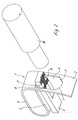
- the essentially loop-shaped tension spring 1 of the tension spring clamp has one leg lying on the cooperating busbar 2 3, a back area 4 and an adjoining clamping leg 5.
- the clamping leg 5 there is a passage opening 6 through which the busbar 2 occurs when the tension spring is placed on the busbar becomes.
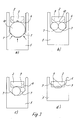
- Figure a illustrates that this centering a particularly secure clamping for a single conductor 10 to be connected and thus contacting, because in relation to the clamping leg 5 result in several clamping points, indicated by arrows in Figure a are.
- Figure b of Figure 3 illustrates the reliable clamping and thus contacting two conductors of the same diameter, their position to each other, to Clamp legs and to the busbar in the clamping phase thanks to the centering and compaction results automatically.
- Figure c of the clamping scheme according to Figure 3 illustrates the also guaranteed reliable clamping thanks to the centering and compacting in the Taper zone also for two conductors of different diameters.
- the illustration d of the clamping scheme according to FIG. 3 illustrates that under extensive conditions Entry of the bevels 7 of the passage opening 6 of the clamping leg 5 into the Recesses 8 also a very small conductor in the bottom area of the taper zone can be reliably clamped and contacted.
- the rejuvenation zone can also be reliable and easy too Multi-wire conductors, especially fine-wire conductors, reliably connected become.
- the underside of the busbar 2 is possible Conductor connection area provided with a corrugation 11, which is particularly good Down the ladder.
- the center can a bulge 12 may be provided on the underside of the busbar 2 in which in some applications is a conductor with part of its outer sheath can insert, which can also contribute to secure fixing.
- it may be appropriate to the bottom of the busbar insofar as to be left in the possible clamping zone as a whole, as in FIG 4 shown.
Landscapes
- Installation Of Bus-Bars (AREA)
- Clamps And Clips (AREA)
- Suspension Of Electric Lines Or Cables (AREA)
- Connections Effected By Soldering, Adhesion, Or Permanent Deformation (AREA)
Abstract
Description
- Figur 1
- eine Zugfederklemme vor Einführung des elektrischen Leiters, noch in geschlossenem Zustand, in Perspektive,
- Figur 2
- die Zugfederklemme nach Figur 1 nunmehr in geöffnetem, zur Aufnahme des Leiters bereiten Zustand,
- Figur 3
- ein Klemmschema für unterschiedliche Leiterklemmungen,
- Figur 4
- eine Einzelansicht einer weiteren Ausführungsform der Stromschiene.
Claims (5)
- Zugfederklemme mit einer Stromschiene (2) und einer Zugfeder (1), die einen auf der Stromschiene (2) aufliegenden Schenkel (3), einen gebogenen Rückenbereich (4) und einen Klemmschenkel (5) hat, in dem sich eine Durchtrittsöffnung (6) für die Stromschiene (2) befindet, wobei die untere Begrenzung der Durchtrittsöffnung (6) einen eingeführten elektrischen Leiter (10) an der Unterseite der Stromschiene (2) festklemmt, dadurch gekennzeichnet, daß die untere Begrenzung der Durchtrittsöffnung (6) durch zum freien Ende des Klemmschenkels (5) hin konvergierende Schrägen (7) leiterzentrierend ausgebildet ist.
- Zugfederklemme nach Anspruch 1, dadurch gekennzeichnet, daß in der Stromschiene (2) beidseitig mit den Schrägen (7) der Durchtrittsöffnung (6) korrespondierende Ausnehmungen (8) vorgesehen sind, in die die Schrägen (7) der Durchtrittsöffnung (6) bei Leiterklemmung eintreten können.
- Zugfederklemme nach Anspruch 2, dadurch gekennzeichnet, daß die Ausnehmungen (8) einen Boden (9) mit einem dem Verlauf der Schrägen (7) entsprechenden Schrägverlauf haben.
- Zugfederklemme nach einem der vorhergehenden Ansprüche dadurch gekennzeichnet, daß die Stromschiene (2) unterseitig in ihrem Leiterklemmbereich eine Riffelung (11) aufweist.
- Zugfederklemme nach einem der vorhergehenden Ansprüche, dadurch gekennzeichnet, daß die Stromschiene (2) mittig auf ihrer Unterseite im Klemmbereich eine Einwölbung (12) aufweist.
Applications Claiming Priority (2)
| Application Number | Priority Date | Filing Date | Title |
|---|---|---|---|
| DE19916755A DE19916755B4 (de) | 1999-04-14 | 1999-04-14 | Zugfederklemme |
| DE19916755 | 1999-04-14 |
Publications (2)
| Publication Number | Publication Date |
|---|---|
| EP1045474A2 true EP1045474A2 (de) | 2000-10-18 |
| EP1045474A3 EP1045474A3 (de) | 2002-02-13 |
Family
ID=7904477
Family Applications (1)
| Application Number | Title | Priority Date | Filing Date |
|---|---|---|---|
| EP00103009A Withdrawn EP1045474A3 (de) | 1999-04-14 | 2000-02-15 | Zugfederklemme |
Country Status (3)
| Country | Link |
|---|---|
| US (1) | US6270383B1 (de) |
| EP (1) | EP1045474A3 (de) |
| DE (1) | DE19916755B4 (de) |
Cited By (4)
| Publication number | Priority date | Publication date | Assignee | Title |
|---|---|---|---|---|
| FR2954604A1 (fr) * | 2009-12-22 | 2011-06-24 | Legrand France | Borne de connexion electrique automatique et appareillage electrique comportant une telle borne |
| EP2466689A1 (de) * | 2010-12-15 | 2012-06-20 | BJB GmbH & Co. KG | Klemmkontakt |
| WO2013110363A1 (de) | 2012-01-26 | 2013-08-01 | Pepperl + Fuchs Gmbh | Zugfeder-schraub-klemme |
| WO2020050798A3 (en) * | 2018-07-04 | 2020-06-04 | Eae Elektrik Asansor Endustrisi Insaat Sanayi Ve Ticaret Anonim Sirketi | An additional connection module for busbar |
Families Citing this family (22)
| Publication number | Priority date | Publication date | Assignee | Title |
|---|---|---|---|---|
| US6607227B1 (en) * | 2000-06-28 | 2003-08-19 | Siemens Automotive Corporation | Sawtooth terminal blade gripper and method of gripping |
| FR2815177B1 (fr) * | 2000-10-10 | 2005-02-11 | Entrelec Sa | Ressort de connexion et bloc de raccordement mettant en oeuvre un tel ressort |
| EP1253670B1 (de) | 2001-04-23 | 2006-04-26 | Weidmüller Interface GmbH & Co. | Federklemme und Federklemmenreihung |
| DE10153170C1 (de) * | 2001-10-27 | 2003-02-20 | Phoenix Contact Gmbh & Co | Federkraftklemme |
| US6893286B2 (en) * | 2003-09-06 | 2005-05-17 | Weidmüller Interface GmbH & Co. KG | Connector apparatus adapted for the direct plug-in connection of conductors |
| DE102005060410A1 (de) * | 2005-12-15 | 2007-06-21 | Phoenix Contact Gmbh & Co. Kg | Elektrische Klemme |
| DE202007015004U1 (de) * | 2007-10-29 | 2009-03-12 | Weidmüller Interface GmbH & Co. KG | Anschlußvorrichtung mit einer Stromschiene |
| TWI420070B (zh) * | 2010-05-18 | 2013-12-21 | Hon Hai Prec Ind Co Ltd | 線纜長度測量裝置 |
| US9130285B2 (en) * | 2012-09-05 | 2015-09-08 | Hubbell Incorporated | Push wire connector having a spring biasing member |
| DE102013109640B4 (de) | 2013-09-04 | 2018-05-24 | Wago Verwaltungsgesellschaft Mbh | Federkraftanschlussklemme und Klemmenbauelement |
| US9336977B1 (en) | 2015-04-03 | 2016-05-10 | Eaton Corporation | Electrical switching apparatus and secondary disconnect assembly with terminal retention and correction features therefor |
| US9570261B2 (en) | 2015-04-03 | 2017-02-14 | Eaton Corporation | Electrical switching apparatus and secondary disconnect assembly with contact alignment features therefor |
| US9576762B2 (en) | 2015-04-03 | 2017-02-21 | Eaton Corporation | Electrical switching apparatus and secondary disconnect assembly with error-proofing features therefor |
| US9396889B1 (en) | 2015-04-03 | 2016-07-19 | Eaton Corporation | Electrical switching apparatus and secondary disconnect assembly with cradle assembly alignment and positioning features therefor |
| CN106887726B (zh) * | 2015-12-15 | 2019-11-08 | 泰科电子(上海)有限公司 | 夹持装置、电连接器和连接器组件 |
| DE102018101381A1 (de) * | 2018-01-23 | 2019-07-25 | Harting Electric Gmbh & Co. Kg | Steckverbinder mit Federkontakt |
| DE102018127284A1 (de) * | 2018-10-31 | 2020-04-30 | Bals Elektrotechnik Gmbh & Co. Kg | Klemmfeder für eine schraubenlose Anschlussklemme |
| DE102018129950B4 (de) * | 2018-11-27 | 2025-10-09 | Phoenix Contact Gmbh & Co. Kg | Federkraftklemme zum Verbinden von Leitern |
| DE102018129949A1 (de) * | 2018-11-27 | 2020-05-28 | Phoenix Contact Gmbh & Co. Kg | Federkraftklemme zum Verbinden von Leitern |
| DE102020109470A1 (de) | 2020-04-04 | 2021-10-07 | WAGO Verwaltungsgesellschaft mit beschränkter Haftung | Vorrichtung und verfahren zum verbinden zweier elektrischer leiter |
| CN113612039B (zh) * | 2021-07-21 | 2023-06-30 | 恩尼特克电子科技(深圳)有限公司 | 螺旋弹簧式锁线端子台 |
| BE1030956B1 (de) * | 2022-10-10 | 2024-05-14 | Phoenix Contact Gmbh & Co | Elektronisches Gerät und Kontaktelement zur Verwendung in einem elektronischen Gerät |
Family Cites Families (10)
| Publication number | Priority date | Publication date | Assignee | Title |
|---|---|---|---|---|
| US985821A (en) * | 1909-11-17 | 1911-03-07 | Dean Electric Co | Electrical terminal connector. |
| DE6802185U (de) * | 1968-10-14 | 1969-03-27 | Wago Kontakttechnik Gmbh | Schraubenlose anschluss- und verbindungsklemme |
| CH516232A (de) * | 1971-04-01 | 1971-11-30 | Oskar Woertz Inh H & O Woertz | Schraubenlose elektrische Schnell-Verbindungsklemme |
| DE3122303A1 (de) * | 1981-06-04 | 1983-01-27 | Felten & Guilleaume Energietechnik GmbH, 5000 Köln | Federklemme zum anschluss isolierter elektrischer leiter |
| JPH05129039A (ja) * | 1991-11-06 | 1993-05-25 | Kyowa Electron Instr Co Ltd | 簡易操作型ターミナル装置およびその製造方法 |
| DE4216927C1 (de) * | 1992-05-22 | 1993-09-23 | F. Wieland Elektrische Industrie Gmbh, 96052 Bamberg, De | |
| DE4237733C1 (de) * | 1992-11-09 | 1993-12-23 | Weidmueller Interface | Schraubenlose Anschlußklemme für elektrische Leiter |
| GB9508153D0 (en) * | 1995-04-21 | 1995-06-07 | Amp Gmbh | Spring clamp terminal |
| DE29608178U1 (de) * | 1996-05-06 | 1996-07-25 | Weidmüller Interface GmbH & Co, 32760 Detmold | Zugfederanschluß mit einsteckbarem Anschlagelement |
| DE19632187C2 (de) | 1996-08-09 | 1998-07-02 | Weidmueller Interface | Zugfederanschluß für elektrische Leiter |
-
1999
- 1999-04-14 DE DE19916755A patent/DE19916755B4/de not_active Expired - Fee Related
-
2000
- 2000-02-15 EP EP00103009A patent/EP1045474A3/de not_active Withdrawn
- 2000-04-04 US US09/542,849 patent/US6270383B1/en not_active Expired - Fee Related
Cited By (5)
| Publication number | Priority date | Publication date | Assignee | Title |
|---|---|---|---|---|
| FR2954604A1 (fr) * | 2009-12-22 | 2011-06-24 | Legrand France | Borne de connexion electrique automatique et appareillage electrique comportant une telle borne |
| EP2466689A1 (de) * | 2010-12-15 | 2012-06-20 | BJB GmbH & Co. KG | Klemmkontakt |
| CN102570068A (zh) * | 2010-12-15 | 2012-07-11 | Bjb两合公司 | 夹紧触点 |
| WO2013110363A1 (de) | 2012-01-26 | 2013-08-01 | Pepperl + Fuchs Gmbh | Zugfeder-schraub-klemme |
| WO2020050798A3 (en) * | 2018-07-04 | 2020-06-04 | Eae Elektrik Asansor Endustrisi Insaat Sanayi Ve Ticaret Anonim Sirketi | An additional connection module for busbar |
Also Published As
| Publication number | Publication date |
|---|---|
| DE19916755B4 (de) | 2007-06-28 |
| EP1045474A3 (de) | 2002-02-13 |
| US6270383B1 (en) | 2001-08-07 |
| DE19916755A1 (de) | 2000-10-19 |
Similar Documents
| Publication | Publication Date | Title |
|---|---|---|
| DE19916755B4 (de) | Zugfederklemme | |
| DE2209688C3 (de) | Einsteckmutter | |
| DE2553558C3 (de) | Elektrischer Steckanschluß | |
| DE102015114697B4 (de) | Halterahmen für Steckverbindermodule | |
| DE2150732C3 (de) | Elektrischer Verbinder | |
| DE2149838C3 (de) | Elektrisches Kupplungselement | |
| DE4020339A1 (de) | Verbindervorrichtung zur verwendung bei feinem draht | |
| DE8209249U1 (de) | Verbindungselement, insbesondere für Fernmeldeleitungen | |
| DE2213301C3 (de) | Schraubenlose elektrische Schnell-Verbindungsklemme | |
| CH677164A5 (de) | ||
| DE3020990C2 (de) | Elektrische Anschluß- oder Verbindungsklemme für nicht abisolierte Leitungsenden | |
| DE10010719C1 (de) | Brücker | |
| CH667163A5 (en) | Spring clamp testing device - has outer rigid test pins and intermediate spring contact pins cooperating with respective clamp contacts | |
| DE4224444C2 (de) | Prüfstecker für Reihenklemmen | |
| DE69300207T2 (de) | Sicherheitsverbinder für elektrische Verteilervorrichtung mit mehrfachen Abzweigungen. | |
| DE1202581B (de) | Befestigung eines als Steckerbuchse ausgebildeten bolzenfoermigen Bauteils | |
| DE2427215C2 (de) | Mehrpoliger Steckverbinder mit Werkzeug | |
| EP4371189A1 (de) | Klemmkörper und verbindungsklemme für einen elektrischen leiter | |
| DE2142850B2 (de) | Elektrische klemmverbindungsvorrichtung zum anschluss eines oder mehrerer isolierter draehte an einem anschlusselement | |
| DE2437399C3 (de) | Klemmelement zum Anschluß isolierter elektrischer Leiter | |
| DE548520C (de) | Stecker mit an den Kontaktstiften angebrachten Stechspitzen | |
| DE4017815C2 (de) | Kontaktklammer für Schneidklemmverbindungen | |
| EP1212811B1 (de) | Vorrichtung zum kontaktieren einer elektrischen leitung, insbesondere einer flachbandleitung | |
| DE10205613B4 (de) | Kontaktelement | |
| DE19724774C1 (de) | Einrichtung zum Kontaktieren eines Kabels |
Legal Events
| Date | Code | Title | Description |
|---|---|---|---|
| PUAI | Public reference made under article 153(3) epc to a published international application that has entered the european phase |
Free format text: ORIGINAL CODE: 0009012 |
|
| AK | Designated contracting states |
Kind code of ref document: A2 Designated state(s): AT BE CH CY DE DK ES FI FR GB GR IE IT LI LU MC NL PT SE |
|
| AX | Request for extension of the european patent |
Free format text: AL;LT;LV;MK;RO;SI |
|
| PUAL | Search report despatched |
Free format text: ORIGINAL CODE: 0009013 |
|
| AK | Designated contracting states |
Kind code of ref document: A3 Designated state(s): AT BE CH CY DE DK ES FI FR GB GR IE IT LI LU MC NL PT SE |
|
| AX | Request for extension of the european patent |
Free format text: AL;LT;LV;MK;RO;SI |
|
| 17P | Request for examination filed |
Effective date: 20020117 |
|
| AKX | Designation fees paid |
Free format text: AT BE CH CY DE DK ES FI FR GB GR IE IT LI LU MC NL PT SE |
|
| GRAP | Despatch of communication of intention to grant a patent |
Free format text: ORIGINAL CODE: EPIDOSNIGR1 |
|
| GRAS | Grant fee paid |
Free format text: ORIGINAL CODE: EPIDOSNIGR3 |
|
| STAA | Information on the status of an ep patent application or granted ep patent |
Free format text: STATUS: THE APPLICATION HAS BEEN WITHDRAWN |
|
| 18W | Application withdrawn |
Effective date: 20060831 |