EP1041453A2 - Récipient d'alimentation en toner et appareil de formation d'images - Google Patents
Récipient d'alimentation en toner et appareil de formation d'images Download PDFInfo
- Publication number
- EP1041453A2 EP1041453A2 EP00302538A EP00302538A EP1041453A2 EP 1041453 A2 EP1041453 A2 EP 1041453A2 EP 00302538 A EP00302538 A EP 00302538A EP 00302538 A EP00302538 A EP 00302538A EP 1041453 A2 EP1041453 A2 EP 1041453A2
- Authority
- EP
- European Patent Office
- Prior art keywords
- toner
- container
- main assembly
- shutter
- supply container
- Prior art date
- Legal status (The legal status is an assumption and is not a legal conclusion. Google has not performed a legal analysis and makes no representation as to the accuracy of the status listed.)
- Granted
Links
Images


Classifications
-
- G—PHYSICS
- G03—PHOTOGRAPHY; CINEMATOGRAPHY; ANALOGOUS TECHNIQUES USING WAVES OTHER THAN OPTICAL WAVES; ELECTROGRAPHY; HOLOGRAPHY
- G03G—ELECTROGRAPHY; ELECTROPHOTOGRAPHY; MAGNETOGRAPHY
- G03G15/00—Apparatus for electrographic processes using a charge pattern
-
- G—PHYSICS
- G03—PHOTOGRAPHY; CINEMATOGRAPHY; ANALOGOUS TECHNIQUES USING WAVES OTHER THAN OPTICAL WAVES; ELECTROGRAPHY; HOLOGRAPHY
- G03G—ELECTROGRAPHY; ELECTROPHOTOGRAPHY; MAGNETOGRAPHY
- G03G15/00—Apparatus for electrographic processes using a charge pattern
- G03G15/06—Apparatus for electrographic processes using a charge pattern for developing
- G03G15/08—Apparatus for electrographic processes using a charge pattern for developing using a solid developer, e.g. powder developer
- G03G15/0822—Arrangements for preparing, mixing, supplying or dispensing developer
- G03G15/0877—Arrangements for metering and dispensing developer from a developer cartridge into the development unit
- G03G15/0881—Sealing of developer cartridges
- G03G15/0886—Sealing of developer cartridges by mechanical means, e.g. shutter, plug
-
- G—PHYSICS
- G03—PHOTOGRAPHY; CINEMATOGRAPHY; ANALOGOUS TECHNIQUES USING WAVES OTHER THAN OPTICAL WAVES; ELECTROGRAPHY; HOLOGRAPHY
- G03G—ELECTROGRAPHY; ELECTROPHOTOGRAPHY; MAGNETOGRAPHY
- G03G15/00—Apparatus for electrographic processes using a charge pattern
- G03G15/06—Apparatus for electrographic processes using a charge pattern for developing
- G03G15/08—Apparatus for electrographic processes using a charge pattern for developing using a solid developer, e.g. powder developer
- G03G15/0822—Arrangements for preparing, mixing, supplying or dispensing developer
- G03G15/0848—Arrangements for testing or measuring developer properties or quality, e.g. charge, size, flowability
- G03G15/0849—Detection or control means for the developer concentration
- G03G15/0855—Detection or control means for the developer concentration the concentration being measured by optical means
-
- G—PHYSICS
- G03—PHOTOGRAPHY; CINEMATOGRAPHY; ANALOGOUS TECHNIQUES USING WAVES OTHER THAN OPTICAL WAVES; ELECTROGRAPHY; HOLOGRAPHY
- G03G—ELECTROGRAPHY; ELECTROPHOTOGRAPHY; MAGNETOGRAPHY
- G03G15/00—Apparatus for electrographic processes using a charge pattern
- G03G15/06—Apparatus for electrographic processes using a charge pattern for developing
- G03G15/08—Apparatus for electrographic processes using a charge pattern for developing using a solid developer, e.g. powder developer
- G03G15/0822—Arrangements for preparing, mixing, supplying or dispensing developer
- G03G15/0865—Arrangements for supplying new developer
- G03G15/0867—Arrangements for supplying new developer cylindrical developer cartridges, e.g. toner bottles for the developer replenishing opening
- G03G15/087—Developer cartridges having a longitudinal rotational axis, around which at least one part is rotated when mounting or using the cartridge
- G03G15/0872—Developer cartridges having a longitudinal rotational axis, around which at least one part is rotated when mounting or using the cartridge the developer cartridges being generally horizontally mounted parallel to its longitudinal rotational axis
-
- G—PHYSICS
- G03—PHOTOGRAPHY; CINEMATOGRAPHY; ANALOGOUS TECHNIQUES USING WAVES OTHER THAN OPTICAL WAVES; ELECTROGRAPHY; HOLOGRAPHY
- G03G—ELECTROGRAPHY; ELECTROPHOTOGRAPHY; MAGNETOGRAPHY
- G03G15/00—Apparatus for electrographic processes using a charge pattern
- G03G15/06—Apparatus for electrographic processes using a charge pattern for developing
- G03G15/08—Apparatus for electrographic processes using a charge pattern for developing using a solid developer, e.g. powder developer
- G03G15/0822—Arrangements for preparing, mixing, supplying or dispensing developer
- G03G15/0865—Arrangements for supplying new developer
- G03G15/0875—Arrangements for supplying new developer cartridges having a box like shape
-
- G—PHYSICS
- G03—PHOTOGRAPHY; CINEMATOGRAPHY; ANALOGOUS TECHNIQUES USING WAVES OTHER THAN OPTICAL WAVES; ELECTROGRAPHY; HOLOGRAPHY
- G03G—ELECTROGRAPHY; ELECTROPHOTOGRAPHY; MAGNETOGRAPHY
- G03G2215/00—Apparatus for electrophotographic processes
- G03G2215/06—Developing structures, details
- G03G2215/066—Toner cartridge or other attachable and detachable container for supplying developer material to replace the used material
- G03G2215/0663—Toner cartridge or other attachable and detachable container for supplying developer material to replace the used material having a longitudinal rotational axis, around which at least one part is rotated when mounting or using the cartridge
- G03G2215/0665—Generally horizontally mounting of said toner cartridge parallel to its longitudinal rotational axis
- G03G2215/067—Toner discharging opening covered by arcuate shutter
-
- Y—GENERAL TAGGING OF NEW TECHNOLOGICAL DEVELOPMENTS; GENERAL TAGGING OF CROSS-SECTIONAL TECHNOLOGIES SPANNING OVER SEVERAL SECTIONS OF THE IPC; TECHNICAL SUBJECTS COVERED BY FORMER USPC CROSS-REFERENCE ART COLLECTIONS [XRACs] AND DIGESTS
- Y10—TECHNICAL SUBJECTS COVERED BY FORMER USPC
- Y10S—TECHNICAL SUBJECTS COVERED BY FORMER USPC CROSS-REFERENCE ART COLLECTIONS [XRACs] AND DIGESTS
- Y10S222/00—Dispensing
- Y10S222/01—Xerography
Definitions
- the present invention relates to a toner supply container for supplying toner to an image forming apparatus such as an electrophotographic copying machine or an electrophotographic printer. It also relates to an image forming apparatus in which such a toner supply container is removably installable.
- An image forming apparatus to which the present invention is preferably applicable is of a type which employs an electrophotographic image formation system to form images on a piece of recording medium.
- an electrophotographic image forming apparatus there are electrophotographic copying machines, electrophotographic printers (laser beam printers, LED printers, or the like), facsimile machines, word processors, and the like.
- toner in the form of microscopic particles has been used as developer for an image forming apparatus such as an electrophotographic copying machine or printer.
- a toner supply container is used to replenish the image forming apparatus with a fresh supply of toner. Since toner is in the form of extremely microscopic particles, it tends to easily scatter, creating a problem.
- an operator, and/or the environment in which the operator words tends to be contaminated with toner which is being replenished, or a small amount of the toner which remains in a toner supply container after replenishment, scatters.
- the toner supply container is provided with a handle, which is a rotational member, so that the shutters are opened or closed by a rotational force transferring means, such as a gear train, with which the image forming apparatus is provided.
- the drive train through which driving force for opening or closing the shutters is transmitted from the handle to the shutters is constructed with low cost, that is, without using high precision components, it is virtually impossible to avoid such a problem that the components fit loosely with each other, which results in an excessive amount of play, causing thereby gear backlash and/or distortion of the driving train.
- the ratio between an input stroke and an output stroke does not become 1:1.
- the opened shutter sometimes fails to be returned to the original position, that is, the original closed position.
- misalignment may occur between the two shutters, which makes it impossible to pull the toner supply container out of the image forming apparatus main assembly, or causes the shutter on the main assembly side to fail to return to the closed position, making it impossible to install a brand-new toner supply container (whose shutter is at the original position, or the correct position). This is a problem.
- the primary object of the present invention is to provide a combination of a toner supply container and an image forming apparatus, which makes the driving force transmitting portion of the rotational member engage with the rotational force transmitting means, always at the same position.
- the second object of the present invention is to provide a combination of a toner supply container and an image forming apparatus, by which the toner supply container shutter can be smoothly opened or closed.
- the third object of the present invention is to provide a combination of a toner supply container and an image forming apparatus, which causes the opened toner supply container shutter to always return to the original position, or the original closed position, as it is closed.
- the fourth object of the present invention is to provide a combination of a toner supply container and an image forming apparatus, which does not suffer from a problem that the toner supply container cannot be installed into, or removed from, the main assembly of an image forming apparatus because of the misalignment between the shutter on the toner supply container side and the shutter on the apparatus main assembly side.
- This toner supply container used for supplying the main assembly of an electrophotographic image forming apparatus with toner.
- This toner supply container comprises a toner containing portion, a toner outlet for discharging the toner contained in the toner containing portion, a shutter for opening or closing the toner outlet, and a driving force receiving portion for receiving the driving force for moving the shutter to open the toner outlet.
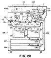
- Figure 28 is a vertical sectional view of an electrophotographic image forming apparatus in which there is a toner supply container in accordance with the present invention.
- An original 101 is placed on a glass plate 102 for an original, by an operator.
- an optical image of the original 101 is formed on a photosensitive drum 104 as an image bearing member by the plurality of mirrors and lenses which an optical portion 103 comprises.
- one of the feeder cassettes 105 - 108 in which recording media P (for example, paper, OHP sheet, or the like; hereinafter, "sheet”) are stored in layers is selected on the basis of the sheet size information inputted through a control panel (unillustrated) by the operator.
- the roller of the selected feeder cassette is rotated to feed out a single sheet of recording medium P.
- the recording sheet P After being fed out of the feeder cassette, the recording sheet P is conveyed to a registration roller 110 through a conveyance path 109.
- the registration roller 110 conveys the recording sheet P to the photosensitive drum 104 in synchronism with the rotational timing for the photosensitive drum 104 and the scanning timing for the optical portion 103.
- the toner image on the photosensitive drum 104 is transferred by a transferring means 111.
- the recording sheet P is separated from the photosensitive drum 104 by a separating means 112.
- the recording sheet P is conveyed to a fixing portion 114 by a conveying portion 113.
- the fixing portion 114 the toner image on the recording sheet P is fixed to the recording sheet P with the application of heat and pressure.
- a developing apparatus 201 In an electrophotographic image forming apparatus structured as described above, a developing apparatus 201, a cleaning means 202, and a primary charging means 203 are disposed around the photosensitive drum 104.
- the developing apparatus 201 develops, with the use of toner, an electrostatic latent image formed on the photosensitive drum 104.
- a toner supplying apparatus 100 for supplying the developing apparatus 201 with toner is removably installed in the apparatus main assembly 124.
- the developing apparatus 201 comprises a development roller 201a which maintains a microscopic gap (approximately 300 ⁇ m) from the photosensitive drum 104. During development, a thin layer of toner is formed on the peripheral surface of the development roller 201a by the development blade 201b. Then, as development bias is applied to the development roller 201a, the electrostatic latent image which has been formed on the photosensitive drum 104 is developed.
- the charging means 203 is a means for charging the photosensitive drum 104.
- the cleaning means 202 is a means for removing the toner which remains on the photosensitive drum 104.
- the reduction in the amount of the toner in the developing apparatus 201 caused by development is compensated for by a fresh supply of toner gradually delivered by a toner supplying apparatus 100 with which the main apparatus of the image forming apparatus is provided.
- the depletion of the toner is reported to a warning section 124a. Then, an operator opens the lid 121, which covers the opening 122 with which the main assembly 124 is provided, as shown in Figure 38. Inside the opening 122, a holder 31 (installing means, more specifically, main assembly 54 of toner supplying apparatus) in which the toner supply container 1 is removably installable is provided. Into this holder 31, the toner supply container 1 is inserted in its longitudinal direction.
- the toner supply container 1 is guided in its longitudinal direction by a guide, with which the holder 31 is provided, and which extends in the longitudinal direction of the holder 31, until the leading end of the toner supply container 1 reaches a predetermined point. Then, as the operator rotates the handle 15 of the toner supply container 1 after the leading end of the toner supply container 1 reaches the predetermined point, the toner within the toner supply container 1 is supplied to the developing apparatus 201. Then, as the operator closes the lid 121, the power switch is turned on, readying the image forming apparatus for image formation.
- a conveying member 29 (which will be described later) within the toner supply container 1 rotates to send the toner into the case 48. Then, as the amount of the toner within the case 48 reaches a predetermined level, the conveying member 29 stops. The process is repeated. If the toner is not supplied even though the sensor within the case 48 sends out the aforementioned signal, a message which suggests the exchange of the toner supply container 1 is displayed by the warning section 124a.
- the toner supply container 1 in this embodiment ( Figures 1 - 3) is installed in the toner supplying apparatus 100 in an image forming apparatus, and is left there so that the toner within the toner supply container 1 is gradually supplied to the development station until the toner within the toner supply container 1 is depleted.
- it is of the so-called built-in type.
- the present invention does not require that the type of the toner supply container 1 is limited to the one described above; the present invention is also applicable to, for example, a toner supply container of the so-called integral type, which not only holds toner but also supplies it to the development station.
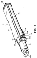
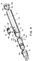
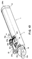
- the toner supply container 1 has a toner containing portion 11 which is the main portion, and first and second flanges 12 and 13, respectively, which are attached to the corresponding longitudinal ends of the toner containing portion 11. It also has a cap 14 which is inserted into the first flange 12, and a handle 15, a rotational member, which is rotationally fitted around the first flange 12. Further, it has a container shutter 16 which exposes or covers the toner outlet 11a of the toner containing portion 11. Within the toner containing portion 11, a toner conveying member 29 is disposed as a toner conveying means (Figure 5).
- the toner containing portion 11 is shaped so that its cross section perpendicular to its longitudinal direction becomes a combination of an approximately semi-circular portion 11g and a rectangular portion 11h. It is in the form of a hollow tube with the above described cross section, and the toner is stored within this toner containing portion 11.
- the toner containing portion 11 is provided with a toner outlet 11a, which is in the curved wall portion of the toner containing portion 11.
- the toner containing portion 11 is also provided with a pair of shutter supporting members 11e, which are located on the curved wall portion of the toner containing portion 11, one on the front side of the toner outlet 11a and the other on the rear side, in terms of the longitudinal direction of the toner containing portion 11, and extend in the circumferential direction of the toner containing portion 11.
- the container shutter 16 is supported by the supporting members 11e so that the container shutter 16 can take a closing position ( Figure 11) at which the container shutter 16 seals the toner outlet 11a, or an exposing position ( Figure 12) to which the container shutter 11 retreats to expose the toner outlet 11a.
- the toner containing portion 11 is provided with a pair of guiding portions 11k, which run in the longitudinal direction of the toner containing portion 11 along the lateral longitudinal edges of the toner containing portion 11.
- These guiding portions 11k are members which regulate the toner supply container 1 so that the toner supply container 1 moves in a straight line when the toner supply container 1 is installed into, or removed from, the toner supplying apparatus 100.
- the toner containing portion 11 is in the form of a tube, the cross section of which is such that its top half is semicircular and its bottom half is rectangular.
- the shape of the toner containing portion 11 does not need to be limited to the above described one.
- the toner containing portion 11 may be shaped so that its cross section perpendicular to its longitudinal direction is circular, elliptical, or square. Further, there is no specific restriction regarding the structure and component count of the toner containing portion 11.
- the toner containing portion 11 is filled with toner in the powder form (hereinafter, all toners are in the powder form).
- toners are in the powder form.
- the first and second flanges 12 and 13 are in the form of a hollow tube, which exactly fits into the corresponding longitudinal ends of the toner containing portion 11. After being exactly fitted into the corresponding longitudinal ends of the toner containing portion 11, they are fixed to the toner containing portion 11 with the use of adhesive to seal the toner containing portion 11.
- the first flange 12 comprises an end plate 12b and a cylindrical portion 12e.
- the axial line of the cylindrical portion 12e coincides with the longitudinal center line of the semicylindrical portion 11g of the toner containing portion 11.
- the first flange 12 comprises a toner inlet 12a, which runs within the cylindrical portion 12e.
- the second flange 13 comprises an end plate 13a.
- the first and second flanges 12 and 13 may be integral with the toner containing portion 11, or a part of the toner containing portion 11.
- the main section of the toner containing portion 11 may be a single piece component.
- the first flange 12 is provided with the toner inlet 12a, the opening of which is located at the longitudinal end, on the upstream side in terms of the direction in which the toner containing portion 11 is inserted.
- the toner inlet 12a is provided with internal ribs 12c, which radially fit within the toner inlet 12a ( Figures 36 and 37).
- the toner inlet 12a is provided with a cylindrical hollow shaft, the axial line of which coincides with that of the toner inlet 12a, and which supports the axle of the toner conveying member which will be described later.
- a handle 15 which will be described later, is fitted. After the toner is filled, the toner inlet 12a is sealed by fitting a cap 14 into the toner inlet 12a.
- the first flange 12 is unitized with the toner containing portion 11 by an appropriate joining means.
- the end plate 13a of the second flange 13 is provided with a hole 13c, into which a driving force transmitting bearing (for example, coupling) for bearing the axle of the toner conveying member 29 and also transmitting the driving force, is fitted from outside the toner containing portion 11. Further, the end plate 13a is provided with a cylindrical portion 13d ( Figures 4 and 5), which projects outward from the outer edge of the hole 13c and supports the peripheral surface of the aforementioned coupling.
- a driving force transmitting bearing for example, coupling
- the handle 15, a rotational member basically comprises three sections: a knob section 15e, a cylindrical hollow section 15h (middle section) with a smaller diameter, and a cylindrical hollow section with a larger diameter.
- the knob section 15e is the outward end of the handle 15, and is in the form of a thick plate with a thicker end
- the cylindrical hollow section with a larger diameter is the inward end of the handle 15, and is open on the inward side.
- the handle 15 is rotationally attached to the toner containing portion 11 by manually fitting the middle section 15h around a handle supporting portion 12f, which is a part of the cylindrical portion 12e located at one of the longitudinal ends of the toner containing portion 11 ( Figures 7 and 8).
- the handle 15 also comprises an engaging portion 15a, which is a driving force transmitting portion, for transmitting the driving force.
- the engaging portion 15a is on the outward facing surface of the handle 15.
- the engaging portion 15a is in the form of a segment gear so that when the toner supply container 1 is inserted into the toner supplying apparatus 100, the engaging portion 1a can engage with the engaging portion 21a of a driving force transmitting member 21 with which the toner supplying apparatus 100 is provided.
- the engaging portion 15a is engageable with the engaging portion 21a through a sequential operation for inserting the toner supply container 1.
- the diving force transmitting member 21 as a rotational force transmitting means comprises a shaft 21s, the engaging portion 21a for receiving the driving force, and an engaging portion 21b for transmitting the driving force.
- the shaft 21s is fitted with the engaging portions 21a an 21b, one for one at its longitudinal ends, and is rotationally supported by the toner supplying apparatus 100.
- the engaging portions 21a and 21b comprise gears with multiple teeth.
- the engaging portion 21a on the driving force reception side in this embodiment comprises a single gear.
- there is no specific restriction regarding the structure or gear count of the engaging portion 21a as long as it is structured to function as a mechanism for receiving the driving force.
- the engaging portion 21b on the driving force transmission side is meshed with the engaging portion 21g on the driving force transmission side as an idler gear which is meshed with the engaging portion 16d, a segment gear, on the driving force reception side.
- the driving force transmitting member 21, a member comprising the shaft 21s, and engaging portions 21a, 21b and 21g, is provided on the apparatus main assembly 124 side of the image forming apparatus.
- one end of a shaft 27 for supporting the toner conveying member 29 is rotationally borne by the hole 12d ( Figure 37), and the other end of the shaft is borne by the bearing 13d fitted in the shaft hole 12d so that the rotational driving force is transmitted through the coupling 26a fixed to this end of the shaft 27.
- the toner conveying member 29 comprises a toner conveying wing 28, which is a flexible member fixed to the shaft 27.
- the coupling 26a is rotationally supported by the toner containing portion 11.
- the toner conveying wing 28 rubs against the inward surface of the toner containing portion 11.
- the toner conveying wing 28 comprises a plurality of segments with a winglet 28a.
- the toner outlet 11a side of the winglet 23a is bent away from the rotational direction of the toner conveying wing 28 so that the toner in the toner containing portion 11 can be conveyed toward the toner outlet 11a.
- the toner outlet 11a is located on the upstream side in terms of the direction in which the toner supply container 1 is inserted into the apparatus main assembly 124. Thus, all winglets 28a extend in the same direction.
- winglets 28a extend in the same direction; the winglets 28a may be different in their extending direction, depending on the positioning of the toner outlet 11a.
- the provision of the toner conveying member 29 is not mandatory. However, the provision of the toner conveying member 29 assures reliable suppliance of the toner.
- a coupling 26a as a driving force receiving member is rotationally supported by the end plate of the toner containing portion 11. Both ends of the coupling 26a in the axial direction are in the form of a shaft coupler. One end of the coupling 26a is positioned within the toner containing portion 11, and is coupled with one end of the shaft 27 of the toner conveying member 29, whereas the other end of the coupling 26a, which is positioned outside the toner containing portion 11, is provided with a rotational force receiving portion.
- this rotational force receiving portion couples with the coupling 44 provided on the toner supplying apparatus 100 side to transmit the rotational force.
- the rotational force receiving portion is in the form of a projection 26a1, a part of which extends in the radial direction of the coupling 26a.
- the couplings 26 and 44 couple with each other as the projections 44a of the coupling 44 fit into the two spaces 26a2 between the two projections 26a1, one for one.
- the container shutter 16 is provided with a pair of sliding portions 16f, which are located at the longitudinal ends, in terms of inserting direction of the toner supply container 1, of the container shutter 16, one for one.
- the sliding portions 16f engage, one for one, with a pair of shutter supporting members 11e as guiding members which extend on the toner containing portion 11 in the circumferential direction of the toner containing portion 11 along the curved edges of the toner outlet 11a, one on the front side and the other on the back side of the outlet 11a, in terms of the inserting direction of the container 1.
- the container shutter 16 slides in the circumferential direction of the toner containing portion 11 to expose or seal the toner outlet 11a.
- the cross section of the container shutter 16 perpendicular to the longitudinal direction of the toner supply container 1 is in the form of an arc, the curvature of which is such that the container shutter 16 perfectly fits along the outer surface of the cylindrical portion 11g of the toner containing portion 11.
- the sliding portions 16f and shutter supporting members 11e their cross section at a plane which includes the axial line of the theoretical hollow cylinder to which the container shutter 16 belongs, are in the form of an interlocking hook ( Figure 6).
- the shape of the cross section of shutter supporting member 11e, i.e., the interlocking hook is the same across the entire length of the member.
- the sliding portion 16f is provided with a plurality of small hook-like horizontal projections 16u which extend inward, relative to the toner outlet 11a, from the upright base portion of the sliding portion 16f.
- the locations of these hook-like horizontal projections 16u correspond one for one with the locations of the plurality of through holes 16t cut through the container shutter 16 along its curved edges.
- each of these horizontal hook-like projections 16u is provided with a tiny projection 16u1 in the form of a character H or T (projects toward the reader side of this page), which is located on the surface of the projection 16u, which faces the shutter supporting member 11e.
- Each projection 16u functions as an elastic member which generates a predetermined amount of pressure for keeping the container shutter 16 tightly in contact with the elastic packing 35. Therefore, even if the pressure which each projection 16u receives from the elastic packing 35 varies depending upon the location of the container shutter 16 during the opening or closing of the container shutter 16, the presence of the plurality of projections 16u averages out the amount of pressure which keeps the container shutter 16 in contact with the elastic packing 35 ( Figure 21).
- the container shutter 16 is provided with the aforementioned driving force receiving engaging portion 16d as a member for receiving the rotational force which is enabled to engage with a gear as the aforementioned driving force transmitting engaging portion 21g as the toner supply container 1 is installed into the toner supplying apparatus 100.
- This engaging portion 16d is provided with a plurality of teeth, and is enabled to engage with the driving force transmitting engaging portion 21g through a sequence of operations for inserting the toner supply container 1 into the toner supplying apparatus 100.
- the driving force receiving engaging portion 16d is cut in the outer surface 16m of the container shutter 16.
- the diameter of the theoretical circle which includes the tooth tips of the segment gear, and the diameter of the theoretical circle which includes the outer surface of the container shutter 16 are rendered practically the same so that space can be saved in terms of the radial direction of the toner supply container 1. Since the engaging portion 16d must be engaged, or disengaged, with the driving force transmitting engaging portion 21g, it is cut in the outer surface of the container shutter 16, close to the curved edge on the coupling 26a side. With this arrangement, the engaging portion 16d engages with, or disengages from, the driving force transmitting engaging portion 21g when the container shutter 16 is in the closed state.
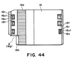
- the driving force transmitting engaging portion 21g with which the toner supplying apparatus 100 is provided, and the driving force receiving portion 16d with which the container shutter 16 is provided, are engaged through a sequence of operations for inserting the toner supply container 1 into the toner supplying apparatus 100. Therefore, the sliding portion 16f (16f1) of the container shutter 16, on the side where the coupling 26a is provided, is made shorter than the driving force receiving engaging portion 16d (portion designated by a referential character A in Figures 4, 10 and 44).
- the sliding portion 16f1 is desired to be configured so that the plane of the edge surface 16h of the container shutter 16, on the downstream side in terms of the longitudinal direction of the toner containing portion 11, which squarely faces the driving force transmitting engaging portion 21g when the toner supply container 1 is inserted into the toner supplying apparatus 100, coincides with the plane of the surfaces of the teeth of the driving force receiving engaging portion 16d, on the downstream side in terms of the inserting direction of the toner supply container 1. Therefore, in this embodiment, a portion 16g is removed to shorten the sliding portion 16f1. Of the two surfaces created by removing the portion 16g, the one perpendicular to the longitudinal direction of the toner containing portion 11 is the aforementioned edge surface 16h. With this arrangement, the driving force transmitting engaging portion 21g and the container shutter 16 do not interfere with each other.
- the sliding portion 16f1 When the container shutter 16 is thick, the sliding portion 16f1 is extended across the entire curved edge of the container shutter 16, and in order to prevent the driving force transmitting engaging portion 21g from colliding with the sliding portion 16f1, the sliding portion 16f1 is provided with an indentation as an equivalent of the aforementioned missing portion 16g to allow the driving force transmitting engaging portion 21g to pass.
- the container shutter 16 fits in an indented portion 34c formed between the surfaces 34b1 of the shutter 34 on the main apparatus side, which exposes or seals the toner inlet 33 with which the toner supplying apparatus 100 is provided. Being fitted in the indented portion 34c, the container shutter 16 can cause the shutter 34 on the main apparatus side to slide as the container shutter 16, which is on the side of the toner supply container 1, is slid.
- the engaging portion 21b and 21g on the driving force transmitting side, with which the apparatus main assembly 124 is provided comprise two gears as shown in Figure 6.
- the container shutter 16 is provided with an elastic portion 16b in the form of an arm which generates such pressure that constantly applies to the handle 15 in the longitudinal direction of the toner containing portion 11.
- the tip of this elastic portion 16b is in contact with the flange 15b of the handle 15.
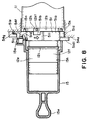
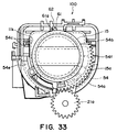
- the toner supplying apparatus 100 is provided with a toner supplying apparatus main assembly 54, a cartridge receiving portion, which comprises a bottom portion 54a and a top portion 54b, the cross sections of which in the direction perpendicular to their lengthwise directions are semicircular and rectangular, respectively, to accommodate the toner containing portion 11.
- the top portion 54b is provided with a plurality of projections 54c for guiding a pair of guide portions 11k of the toner supply container 1.
- the projections 54c are on the inner surface of the top portion 54b.
- One pair of the projections 54c are at the entrance of the toner supplying apparatus main assembly 54, one for each side, and the other pairs are aligned inward of the toner supplying apparatus main assembly 54, one half the pairs being above the line correspondent to the position of the guide portion 11k and the other half being below the same line.
- the bottom portion 54a is provided with a pair of parallel guide rails 55, which are in the inwardly facing surface of the bottom portion 54a and extend in the circumferential direction of the bottom portion 54a.
- the guides 34a of the main assembly shutter 34 are engaged one for one in these guide rails 55.
- the guide rails 55 and the guide 34a are hook-like in their cross section, and interlock with each other.
- the main assembly shutter 34 is supported by the toner supplying apparatus main assembly 54.
- the radius of the inwardly facing surface of the projection 34b of the main assembly shutter 34 is exactly or approximately the same as that of the inwardly facing surface of the container shutter 16.
- the main assembly shutter 34 is provided with a pair of projections 34b, which are located at both edges, one for one, perpendicular to the moving direction of the main assembly shutter 34.
- the main assembly shutter 34 is provided with a main assembly shutter opening 34d. This opening 34d has only to be able to expose or seal the toner supply inlet 33; there may be only one cross section, i.e., a section 34d1.
- the width of inwardly facing surface of the main assembly shutter 34, between the two projections 34b, in the circumferential direction of the main assembly 54, is approximately the same as the width of the inwardly facing surface of the container shutter 16 in the circumferential direction of the main assembly 54. Therefore, as the toner supply container 1 is inserted into the toner supplying apparatus 100, it perfectly fits into the space 34c between the two projections 34b of the main assembly shutter 34, which project inward in the radial direction of the toner supply container 1; the two edges of the container shutter 16, which extend in the longitudinal direction of the main assembly 54, come virtually in contact with the corresponding inwardly facing surfaces 34b1 of the projections 34b.
- the main assembly shutter 34 moves with the container shutter 16.
- the two shutters 16 and 34 are designed so that the toner outlet 11a and the toner supply inlet 33 align with each other, as the container shutter 16 is opened, the toner can be supplied into the developing device 204 by a toner stirring-conveying apparatus 45.
- the main assembly shutter opening 34d and the space 34c are immediately adjacent to each other in the circumferential direction of the main assembly shutter 34, being bordered by the projection 34b.
- the packing member 35 as a sealing member is an elastic member ( Figures 4, 11 - 17). It assures that the toner outlet 11a is airtightly sealed by the container shutter 16. For example, it prevents the toner within the toner containing portion 11 from leaking due to the impact caused by the falling or the like of the toner supply container.
- the packing member 35 is pasted to the outwardly facing surface of the toner containing portion 11 in a manner of surrounding the toner outlet 11a.
- the material for the packing member 35 is rubbery material such as silicon rubber, urethane rubber, foamed polyethylene rubber, or the like, or sponge made of these rubbers.
- it is slightly foamed polyurethane which is 20 - 70 deg. in hardness, no more than 10 % in permanent compressive deformation, 60 - 300 ⁇ m in cell size, 0.15 - 0.50 g/ in density, and 5 - 50 % in compression ratio.
- the packing member 35 is shaped so that the top surface of the portion next to the longitudinal edges of the toner outlet 11a is slanted downward toward the toner outlet 11a.
- the packing member 35 shaped as described above is fixed to the surfaces adjacent to the toner outlet 11a with the use of adhesive or the like.
- the container shutter 16 fits into the indentation 34c (space between the two projections 34b) of the main assembly shutter 34.
- the indentation 34c extends across the main assembly shutter 34 in the longitudinal direction, and the surface 34b1 functions as the guide for the container shutter 16.
- the plane of the inwardly facing surface of the projection 34b i.e., the brim of the main assembly shutter opening 34d, and the plane of the inwardly facing surface of the container shutter 16 are at approximately same level.
- the container shutter 16 is provided with a sealing member 41, which is on the surface on the container side.
- the sealing member 41 is extended downstream, in terms of the closing direction of the container shutter 16, beyond the container shutter 16.
- the sealing member 41 is a member for preventing the toner from entering the gap g between the container shutter 16 and the main assembly shutter 34. As long as this objective is accomplished, the material, shape, size, and method of attachment, of the sealing member 41 are optional.
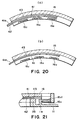
- a piece of 125 ⁇ m thick polyester sheet is pasted, as a sealing member, to the container shutter 16 with the use of double-sided adhesive tape (#5000NC: Nitto Denko Co., Ltd. ( Figure 20).
- the sealing member 41 is structured to cover the projection 34b of the main assembly shutter 34 as described before, it is desired not to interfere with the installation or removal of the toner supply container 11 by hanging up or colliding.
- the main assembly shutter 34 is not necessarily smooth on the container facing surface. But, the sealing member 41 is required to perfectly conform to the container facing surface of the main assembly shutter 34. Because of requirements such as the above, the sealing member 41 is desired to be formed of flexible sheet or sheet formed of elastic material.
- any of various known attaching means may be employed in addition to the aforementioned double-sided adhesive tape as long as it satisfies the requirement that the sealing member 41 does not peels off in spite of repetitive opening and closing of the container shutter 16 which occurs as the toner supply container 1 is repeatedly installed or removed.
- elastomer be used as the material for the sealing member 41, and the sealing member 41 be integrally formed with the container shutter 16 by two color injection molding.
- the elastomer for the sealing member 41 and the material for the container shutter 16 are compatibly selected.
- the sealing member 41 and container shutter 16 may be formed of the same material. In such a case, they can be integrally formed with the use of a simple method.
- the state of the main assembly of the toner supplying apparatus 100 when the toner supply container 1 has been removed, that is, when the container shutter 16 is not in engagement with the main assembly shutter 34 is as shown in Figure 19.
- the main assembly shutter 34 is positioned to seal the toner inlet 33 to prevent foreign substances such as dust from entering the toner supply container 1 through the toner inlet 33.
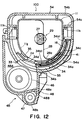
- Figure 12 shows the state in which the toner supply container 1 has been installed, and the toner is being replenished.
- the container shutter 16 has retreated from the toner outlet 11a, allowing a passage to be formed through the toner outlet 11a, main assembly shutter opening 34d, and toner inlet 33.
- the plane of the container facing surface of the container shutter 16 and the plane of the container facing surface of the projection 34b next to the opening 34d of the main assembly shutter 34 is at approximately the same level. Therefore, the sealing member 41 is in contact with the projection 34b of the main assembly shutter 34, keeping the toner passage airtight, and at the same time, preventing the toner from adhering to the surface of the projection 34b of the main assembly shutter 34.
- the toner having been stored in the toner supply container 1 is conveyed toward the toner stirring-conveying apparatus 45, i.e., a toner receiving apparatus, by the function of the toner conveying member 29 contained in the toner supply container 1 through the toner outlet 11a, opening 34d, and toner inlet 33 through which the toner passage has been established.
- the toner stirring-conveying apparatus 45 i.e., a toner receiving apparatus
- the thickness of the sealing member 41 is desired to be no less than 50 ⁇ m and no more than 300 ⁇ m, preferably, no less than 70 ⁇ m and no more than 200 ⁇ m, and ideally, 125 ⁇ m.
- the sealing member If the sealing member is excessively thick, it fails to properly seal the gap between the main assembly shutter 34 and toner supply container 1. On the other hand, if it is excessively thin, it fails to properly perform its primary function, that is, the function to prevent the toner from entering between the container shutter 16 and main assembly shutter 34. As a result, various problems occur while the toner supply container 1 is handled, in particular, while the toner supply container 1 is installed into, or removed from, the toner supplying apparatus 100. For example, the sealing member 41 is peeled back or wrinkled.
- the requirement regarding the thickness of the sealing member 41 can be eliminated by the provision of the structure in which the sealing member 41 is retracted to a point where the sealing member 41 does not contact the packing member 35.
- such a structure makes the shutter stroke substantially longer, making it difficult to give a toner supplying apparatus and a toner supplying container a compact design.
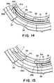
- the toner at the main assembly shutter opening 34d moves undisturbed in the closing direction, and becomes separated from the toner in the toner supply container 1 and the toner in the toner stirring-conveying apparatus 45, as shown in Figure 16.
- the gap G between the main assembly shutter 34 and container shutter 16 passes directly below the toner outlet 11a as shown in Figure 16.
- the sealing member 41 covers this gap g as shown in Figure 16, preventing the toner from entering the gap g.
- the sealing member 41 and container shutter 16 are under the contact pressure generated downward (in drawings) by the resiliency o the packing member 35. Therefore, the portion 41a of the sealing member 41, which extends beyond the edge of the sealing member 41, is also pressed upon the container facing surface of the main assembly shutter 34, not only gaining in sealing performance but also in preventing the toner from adhering to the surface of the projection 34b of the main assembly shutter 34.
- the length by which the aforementioned extension portion 41a extends is desired to be approximately the same as the width of the projection 34b of the main assembly shutter 34. More specifically, it is desired to be set at a value no less than 2 mm and no more than 10 mm, preferably, no less than 4 mm and no more than 8 mm, and ideally, at 6 mm. If the extension portion 41a is excessively short, it is unsatisfactory in terms of effectiveness in preventing the toner invasion of the aforementioned gap g, and also, the aforementioned pocket which the sealing member 41 and toner containing portion 11 form is shallow, failing to retain the toner. In addition, it fails to prevent the toner adhesion to the surface of the projection 34b of the main assembly shutter 34.
- the extension portion 41a is excessively long, it interferes with the installation or removal of the toner supply container 1. For example, it collides with the various portions of the internal surface of the toner supplying apparatus 100, which is a problem.
- the pressure generated by the aforementioned packing member 35 fails to be transmitted to the farthest portion of the extension portion 41a, causing the sealing member 41 to lose in sealing performance.
- the pressure can be transmitted to the farthest portion of the extension portion 41a of the sealing member 41 by increasing the rigidity of the sealing member 41.
- such a practice reduces the ability of the sealing member 41 to conform to the surface of the main assembly shutter 34, also causing the sealing member 41 to lose in sealing performance.
- the extension portion 41a is excessively long, it makes the main assembly shutter opening 34d too small, possibly interfering with the passage of the toner.
- FIG. 17 and 18 A case in which the sealing member 41 is not provided is shown in Figures 17 and 18.
- the gap g between the container shutter 16 and main assembly shutter 34 is exposed to the toner.
- the toner invades the gap g, and the outwardly facing surface of the container shutter 16 is contaminated by the adhesion of the toner which invaded the gap g. Since there is no outlet for the toner which invaded the indentation of the main assembly shutter 34c, i.e., the space between the mutually facing surfaces 34b1 of the projections 34b of the main assembly shutter 34, the toner continues to accumulate there.
- the contamination of the toner supply container 1 worsens. Further, the toner also adheres to the projection 34b of the main assembly shutter 34, and this toner transfers onto the toner supply container 1, on the surface which opposes the projections 34b; in other words, it contaminates the toner supply container 1.
- the ratio with which the packing member 35 is compressed is desired to be as high as possible, since the compressive stress of the packing member 35 is proportional to the compression ratio.
- the compressive stress of the packing is also small, and therefore, the sealing performance of the packing member 35 is at an unsatisfactory level.
- the toner leak due to the impact caused by a fall or the like of the toner supply container when the compression ratio is small, the toner leak due to the impact caused by a fall or the like of the toner supply container.
- the compression ratio is excessively increased, the compression stress of the packing member 35 also becomes excessively high. This improves the packing member 35 in sealing performance, and at the same time, increases load in terms of sliding. As a result, the force required to open or close the container shutter 16 increases.
- a piece of flexible film 42 as a low friction material is pasted to the sealing member 41, on the surface which faces the packing member 35, as shown in Figures 20 and 21, so that the amount of the frictional resistance between the surfaces of the sealing member 41 and packing member 35 is reduced.
- flexible film created by coating silicon oil, silicone wax, silicone containing paint, or the like, on a base film for example, film comprising a single layer of polyester, biaxially stretched polypropylene (OPP), polyamide, polyethylene, or fluorinated resin, or film comprising mixed layers of preceding materials, is used as the material for the flexible film 42.
- the thickness of the layer of the silicone oil on the aforementioned flexible film 42 is desired to be in a range of 0.05 - 2 ⁇ m, preferably, 0.1 - 0.5 ⁇ m. If the thickness of the coated layer of silicone oil is excessively thick, the toner in the toner containing portion 11 is negatively affected, whereas if it is excessively thin, the flexible film 42 is not effective to satisfactorily reduce the force necessary to open or close the shutters.
- the toner supply container 1 with the above described structure was installed in the toner supplying apparatus 100, and the operation for removing the toner supply container 1 before the "no toner" light is lit was repeated.
- the sealing member illustrated in Figure 20, (b) there was no sign of contamination traceable to the toner adhesion to the outwardly facing surface of the container shutter 16 and its adjacencies, and no sign of toner accumulation, providing that the above described structure improved the sealing performance of the sealing member without increasing the driving force necessary to open or close the container shutter 16.
- the extension portion 41a of the sealing member 41 rides onto the projection 34b of the main assembly shutter 34 from the one of the longitudinal ends of the projection 34b of the main assembly shutter 34.
- the projection 34b of the main assembly shutter 34 is chamfered at the opposing downstream corners in terms of the inserting direction, i.e., both downstream corners in Figure 27 (right-hand corner is behind the bottom portion 54b of the toner supplying apparatus main assembly 54), creating the surface 34b2, and the corresponding corners of the container shutter 16 are also chamfered, creating surfaces 16p and 16q ( Figures 39 and 40).
- the main assembly shutter 34 is provided with an entrance guide portion 34e, which is located at the upstream corner of the projection 34b of the main assembly shutter 34 to allow the extension portion 41a of the sealing member 41 to smoothly ride onto the projection 34b.
- This entrance guide portion 34e is a slanted surface, which is located on the upstream corner of the projection 34b, and inclines in the downward and upstream direction from the container facing surface of the projection 34b.
- an entrance guide portion such as the one described above is effective in preventing the extension portion 41a from being damaged at the corners as the extension portion 41a of the sealing member 41 rides onto the projection 34b of the main assembly shutter 34.
- Figures 22 - 26 show the structure for helping the extension portion 41a of the sealing member 41 more smoothly advance onto the projection 34b from the entrance guide portion 34e of the projection 34b of the main assembly shutter 34.
- the sealing member 41 is provided with a single line of perforation 41b, which extends along the base portion of the extension portion 41a.
- Figure 25 is a perspective view of the sealing member 41 provided with the perforation 41b.
- the sealing member 41 may be provided with a groove 41c which extends along the extension portion 41a of the sealing member 41 in the longitudinal direction.
- the groove 41c may be V-shaped or U-shaped in cross section.
- the sealing member 41 inclusive of the extension portion 41a was arc-shaped in cross section.
- the extension portion 41a of the sealing member 41 may be bent at its base line toward the toner containing portion 11, as shown in Figure 23. Being bent as described above, the extension portion 41a can smoothly rides onto the projection 34b of the main assembly shutter 34 as depicted by the double dot chain line in Figure 14. Even if the extension portion 41a is bent in this manner, when the container shutter 16 and main assembly shutter 34 open the toner outlet 11a and main assembly shutter opening 34d, the extension portion 41a is pinched at both longitudinal edges between the packing member 35 and the other projections of the main assembly shutter 34, perpendicular to the projection 34b.
- the extension portion 41a is provided with a sub-extension portion 41d, which extends at an angle from the downstream edge, in terms of the toner supply container 1 installation direction, of the extension portion 41a. In this case, extension portion 41d is positioned not to contact the packing member 35. Therefore, the aforementioned problems do not occur. In other words, this embodiment is the ideal one.
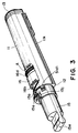
- the toner cartridge is provided with a locking member 51 in the form of a ring so that the handle 15 is locked to the toner containing portion 11 before the toner supply container 1 is installed into the main assembly 124 of an image forming apparatus, and after the toner supply container 1 has been removed from the apparatus main assembly 124 ( Figures 7 and 8).
- the locking member 51 is rotationally fitted around the first flange 12, more specifically, the locking member engagement portion 12g of the first flange portion, that is, the portion immediately next to the end plate 12b of the first flange 12. It is also movable in the direction in which the toner supply container 1 is inserted into, or removed from, the toner supplying apparatus 100 (direction indicated by an arrow mark in Figure 7, and also the opposite direction).
- the locking member 51 comprises a cylindrical ring portion 51a, i.e., the portion which fits around the locking member engagement portion 12g, and is provided with a notch 51b which faces the aforementioned end plate 12b.
- the notch 51b is in engagement with the locking projection 12h with which the first flange 12 is provided.
- the locking member 51 integrally comprises an arm-like springy portion 51c which presses upon the end surface 15i of the handle 15.
- the first flange 12 is provided with a circumferential ridge 12i which is on the cylindrical portion 12e, and circles around the cylindrical portion 12e.
- the handle 15 integrally comprises a stopper 15j, which is formed by inwardly bending a portion of the handle 15.
- the tip of the stopper 15j is kept in contact with the ridge 12i by the resiliency of the aforementioned springy portion 51c, to prevent the handle 15 from slipping off the cylindrical portion 12e of the first flange 12 ( Figure 3). Further, the locking member 51 is kept in contact with the end plate 12b of the first flange 12 by the resiliency of the springy portion 51c.
- the springy portion 51c is gradually reduced in cross section toward its tip, being enabled to evenly bend across its entire length, to prevent the base portion of the springy portion 51c from turning white due to the concentration of the bending stress to the base portion.
- the cross section of the springy portion 51c is rectangular, it is made gradually smaller in the width or thickness direction toward the tip. Therefore, the springy portion 51c gradually reduces in cross section from its base portion to its tip.
- a pair of engagement ribs 51d provided on the outwardly facing surface of the locking member 51 are enabled to move in the installation-removal direction of the toner supply container 1 by being loosely fitted, one for one, in grooves 15k and 15m which are cut in the handle 15 in the installation-removal direction of the toner supply container 1.
- the engagement rib 51i of the locking member 51 is engaged in the groove 15j of the handle 15. Therefore, the handle 15 and locking member 51 are prevented from moving relative to each other in their circumferential direction, but are allowed to move relative to each other in their axial direction ( Figures 37 and 38).
- the length, in terms of the installation-removal direction of the toner supply container 1, of the locking projection 12h provided on the first flange 12 is less than the length of the stroke of the engagement ribs 51d through the grooves 15k and 15m, one for one, in the installation-removal direction of the toner supply container 1. Further, the length, in terms of the installation-removal direction of the toner supply container 1, of the locking projection 12h is less than the length of the stroke of the engagement rib 51i of the locking member 51 through the groove 15j of the handle 15.
- the notch 51b of the locking member 51 is kept engaged with the locking projection 12h of the first flange 12 by the resiliency of the springly portion 51c of the locking member 51. Therefore, whatever state the toner supply container 1 is in, the state in which it is being inserted into the toner supplying apparatus 100, the state in which it is being removed from the toner supplying apparatus 100, or the state in which it is out of the toner supplying apparatus 100, the handle 15 is not allowed to move in its circumferential direction relative to the toner containing portion 11.
- the handle is allowed to slip in its circumferential direction by six degrees, which is equivalent to the amount of the play between the projection 12h provided on the first flange 12 and the notch 51b of the locking portion 51.
- the projection 12h of the first flange 12 is provided also as a means for properly aligning the handle 15 relative to the toner supplying apparatus 100 in terms of the circumferential direction of the handle 15 when installing the toner supply container 1 into the toner supplying apparatus 100. This subject will be described later.
- the handle 15 is rotatable relative to the toner containing portion 11, by six degrees, which is equivalent to the distance between a first position, or the one end of the rotatable range, and a second position, or the other end of the rotatable range.
- the locking member 51 is provided with a latch 51e, which is a thin piece of projection and projects outward in the radial direction from the engagement rib 51d which is adjacent to the springy portion 51c.
- the latch 51e prevents the toner supply container 1 from coming out of the main assembly 54.
- the container shutter 16 and main assembly shutter 34 engage with each other. While the container shutter 16 engages with the main assembly shutter 34, the driving force receiving engaging portion 16d of the container shutter 16 partially meshes with the driving force transmitting engaging portion 21g. and immediately thereafter, the driving force transmitting engaging portion 15a of the handle 15 partially meshes with the driving force receiving engaging portion 21a. after the container shutter 16 partially engages with the main assembly shutter 34, the aforementioned extension portion 41a of the sealing member 41 rides onto the projection 34b past the entrance portion 34e of the main assembly shutter 34.
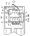
- the handle 15 can be rotated clockwise as seen from the upstream side in terms of the toner supply container 1 installing direction (arrow direction in Figure 8). Then, as the handle 15 is rotated, the locking member 51 rotates together with the handle 15, and immediately, the latch 51e engages into the groove 54g integrally provided in the strike surface 54f of the bottom portion 54a of the toner supplying apparatus main assembly 54 ( Figures 39 and 40).
- This groove 54g extends in the circumferential direction on the cylindrical wall of the bottom portion 54a of the toner supplying apparatus main assembly 54, forming an arc. After engaging into the groove 54g, the latch 51e remains in the groove 54g when the toner outlet 11a and main assembly shutter 34 are opened or closed.
- the toner supply container 1 cannot be simply pulled out of the toner supplying apparatus 100.
- the toner supply container 1 can be removed from the toner supplying apparatus 100 only when the container shutter 16 and main assembly shutter 34 are closed, because the latch 51e is allowed to come out of the arc-like groove only when the container shutter 16 and main assembly shutter 34 are closed.
- the number of the lock releasing projection is only one, moment and/or deformation occurs to the locking member 51, preventing the locking member 51 from smoothly sliding. Further, even if the number of the lock releasing projection is plural, if they are unevenly distributed, the same problem occurs. Therefore, it is desired that a plurality of lock releasing projections are distributed in the circumferential direction with as even as possible intervals.
- two projections are provided, being apart from each other by approximately 180 deg.
- the latch 51e functions also as a lock releasing projection, the angle formed by the radial line connecting the projection 51d1 and the center of the locking member 51 and the radial line connecting the latch 51e and the center of the locking member 51 is approximately 150 deg.
- the locking projection 12h for regulating the angle the locking member rotates is provided with a projection 12h1, which projects from the outwardly facing surface of the locking projection 12h in the radial direction of the locking member 51, and is enabled to engage with the handle 15.
- the angle B the handle 15 rotates from the position at which the projection 12h is engaged in the notch 51b to the position at which the projection 12h1 contacts one of the groove walls 15n of the groove 15m of the engagement rib, is approximately 90 deg.
- the groove 15m is the groove in which the engagement rib 51d (on the side where the latch 51e is located) of the handle 15.
- the notch 51b of the locking member 51 is made wide enough in terms of its central angle A so that a play of 6 deg. is afforded for the handle 15 in terms of its circumferential direction.
- the handle 15 In order to exchange the toner supply container 1 with a fresh one after the toner in the toner supply container 1 was depleted, the handle 15 must be turned to its original position by turning it in the direction opposite to the direction in which the handle 51 is turned during the installation of the toner supply container 1 (counterclockwise as seen from the upstream side in terms of the direction in which the toner supply container 1 is inserted into the toner supplying apparatus 100).
- the latch 51e becomes disengaged from the arc-shaped groove 51e, and the locking member 51 slides back, on the locking member engagement portion 12g, to its original position, i.e., the position at which the locking projection 12h remains engaged in the notch 51b of the ring portion 51a of the locking member 51, due to the resiliency of the springy portion 51c.
- the locking member 51 is under the pressure generated by the springy portion 51c in the direction of the toner containing portion 11, it slides in the direction to cause the aforementioned locking projection 12h and the notch 51b of the locking member 51 to engage with each other, and lock the handle 51.
- the lid 121 with which the apparatus main assembly 124 is provided is opened by 90 deg. toward an operator.
- the guide portion 11k of the toner supply container 1 is engaged into the groove 54h ( Figure 11) between the projections 54c of the toner supplying apparatus 100.
- the toner supply container 1 is inserted into the toner supplying apparatus 100 from the side where the coupling 26a is provided.
- the container shutter 16 of the toner supply container 1 and the main assembly shutter 34 within the toner supplying apparatus 100 engage with each other.
- the driving force transmitting engaging portion 21g and the driving force receiving engaging portion 16d of the container shutter 16 engage with each other.
- the driving force receiving engaging portion 21a on the toner supplying apparatus 100 side and the driving force transmitting engaging portion 15a of the handle 15 engage with each other.
- the rotational driving force i.e., the force applied by the operator
- the rotational driving force is transmitted from the driving force transmitting engaging portion 15a of the handle 15, as a driving force transmitting portion, to the driving force transmitting member 21, as a rotational force transmitting portion, through the driving force receiving engaging portion 21a of the toner supplying apparatus 100.
- this force is further transmitted from the driving force transmitting engaging portion 21g to the driving force receiving engaging portion 16d, as a rotational force receiving portion, of the container shutter 16.
- the container shutter 16 is slid in the circumferential direction of the toner containing portion 11 while engaging with the shutter supporting member 11e of the toner containing portion 11.
- the main assembly shutter 34 moves with the container shutter 16. Therefore, the toner outlet 11a of the tone containing portion 11, the opening 34d of the main assembly shutter 34, and the toner inlet 33 in the toner supplying apparatus 100, are all opened at the same time. Then, toner supplying is started by rotating the toner conveying member 29 through the coupling 26a which receives the driving force from the coupling 44 of the apparatus main assembly 124.
- the toner containing portion 11 does not rotate. Therefore, the toner supply container 1 does not rotate with the handle 15; it remains fixed in the toner supplying apparatus 100.
- the toner supply container 1 is installed into the toner supplying apparatus 100 from the coupling 26a side. This requires that the engaging portion 16d of the container shutter 16 passes by the engaging portion 21a of the apparatus main assembly 124, and engages with the engaging portion 21g. i.e., the inward one, of the apparatus main assembly 124. Therefore, the diameter of the theoretical circle which connects the tips of the teeth of the engaging portion 16d in the form of a segment gear is desired to be smaller than the diameter of the theoretical circle which connects the bases of the teeth of the engaging portion 15a in the form of a segment gear.
- a toner containing portion is not required to move during the toner supplying sequence. Therefore, there is no restriction regarding the shape of a toner containing portion. Therefore, a shape which offers the highest spatial efficiency to a toner containing portion may be employed as the shape for a toner containing portion.
- a shutter and a handle are made into two separate components. Therefore, it is unnecessary for a toner outlet to be next to a handle. Therefore, more latitude can be afforded in designing a toner supply container.
- the driving force applied to the handle is transmitted to the driving force receiving engaging portion of the shutter through a plurality of engaging portions: the engaging portion of the handle, the engaging portion of the driving force transmitting member, and the engaging portion of the shutter. Therefore, it is possible to more freely design these engaging portion in terms of engagement ratio (gear ratio).
- the angle by which the handle must be rotated can be reduced by increasing the engagement ratio (gear ratio) of the handle, and when the torque required to open or close the shutter is high, the torque required to operate (rotate) the handle can be reduced by reducing the engagement ratio (gear ratio) of the handle.
- the angle by which the handle is rotated to open or close the shutter is made to be 90 deg., so that when installing the toner supply container into the toner supplying apparatus, the thick end 15e is vertically positioned, and after the toner is discharged by rotating the handle clockwise by 90 deg., the thick end 15e of the handle 15 is horizontally positioned.
- This arrangement makes it easier for an operator to operate the toner supply container, and also to recognize the state of the toner supply container 1.
- the angle by which the handle 15 is rotated to open or close the shutter is desired to be in a range of 60 - 120 deg.
- the toner supplying apparatus 100 is provided with the toner stirring-conveying apparatus 45.
- the toner supplying apparatus 100 is also provided with the case 48, which is fixed to the toner supplying apparatus main assembly 54 in a manner to cover the toner inlet 33 from below.
- the case 48 is approximately the same as the toner supplying apparatus 100 in the longitudinal dimension.
- the stirring screws 46 and 47 are disposed, being supported by the case 48 so that they can be rotationally driven.
- the stirring screws 46 and 47 are separated by a partition wall 48a which divides the internal space of the case 48 into two chambers 48A and 48B, which are connected to each other through the hole provided in the partition wall 48a on the side opposite to the toner inlet 33, and in which the stirring screws 46 and 47 are disposed, respectively, the stirring screw 46 being diagonally above the stirring screw 47.
- the case 48 is provided with a toner outlet 48b, which is located at the same longitudinal end as the toner inlet 33, and leads to the developing apparatus 201.
- the rotating toner stirring screw 46 conveys the toner, while stirring, through the chamber 48A in the longitudinal direction from the toner inlet 33 side to the opposite side, causing the toner to fall into the chamber 48B through the opening (unillustrated) provided in the partition wall 48a.
- the toner stirring screw 47 i.e., the one at the bottom, conveys, while stirring, the toner in the direction opposite to the toner conveying direction of the toner stirring crew 46.
- the toner is supplied into the developing apparatus 201 through the toner outlet 48B.
- the distance between the final position of the shutter of the toner supply container after the closing stroke, and the original position becomes greater than that in the previous installation. In other words, the distance continues to increase with the repetition of the installation and removal.
- shutter misalignment such as the one described above makes it impossible to remove the toner supply container from the apparatus main assembly, or to install a fresh toner supply container (shutter is at its original position) into the apparatus main assembly, which is a serious problem.
- This problem can be solved by providing a toner supply container and the related structure of the apparatus main assembly with such a feature that requires that when installing a toner supply container, the handle is rotated in the opening direction of the shutter by a predetermined angle, in addition to the theoretically necessary angle, before the handle and shutter begin to engage with the driving train gears on the apparatus main assembly side, and when removing the toner supply container, the handle is rotated in the closing direction of the shutter by the aforementioned predetermined angle, in addition to the theoretically necessary angle.
- This feature compensates for the additional length of stroke which the gear backlash or the like resulting from the excessive play requires, assuring that the shutters are returned to their original positions.
- the handle 15 is provided with a handle projection 61, as a contact portion, which is located on the outwardly facing surface of the handle 15.
- a handle projection 61 as a contact portion, which is located on the outwardly facing surface of the handle 15.
- Figures 41 - 43 which are a schematic plan of the handle projection 61 and its adjacencies as seen from above, the handle projection 61 is shaped like a cam follower, and its portion with a contact surface 61a is narrower than the base portion in terms of the vertical direction in Figures 41 - 43. It is positioned to come in contact with the main assembly projection 62 provided on the inwardly facing surface of the top plate of the bottom portion 54b of the toner supplying apparatus main assembly 54.
- the projections 61 and 62 work in combination as a follower and a cam, respectively.
- the cam portion of the main assembly projection 62 is angled in profile.
- the lift of this cam surface is just enough to make the center angle of the cam portion of the main assembly projection 62, that is, the angle formed by the line connecting the highest point of the cam surface and the center of the toner supplying apparatus main assembly 54 (center of the semicylindrical bottom portion 54a), and the line connecting the base of the cam surface and the center of the toner supplying apparatus main assembly 54, large enough to compensate for the play in the rotational direction between the toner supply container 1 and toner supplying apparatus 100.
- This center angle is no less than 6 deg. In this embodiment, it is 6 deg.
- the handle projection 61 and main assembly projection 62 will be described in positional relationship and function.
- the handle projection 61 reaches a point at which it comes in contact with the main assembly projection 62, on the cam surface, at the point with no lift.
- the driving force transmitting engaging portion 15a of the handle 15 and the driving force receiving engaging portion 21a on the main assembly side are apart from each other by a distance L1, which is equal to a distance L2 by which the handle projection 61 in this state must be moved to receive the highest lift.
- the handle projection 61 slides on the main assembly projection 62 while rotating the handle 15.
- the handle projection 61 slides to the cam crest of the main assembly projection 62
- the handle 15 is rotated by 6 deg.
- the tooth tips of the engaging portion 15a of the handle 15 come in contact with the counterparts of the engaging portion 21a of the toner supplying apparatus 100 at the same time the handle projection 61 reaches the cam crest of the main assembly projection 62.
- the handle 15 is always at the second rotational position as shown in Figures 34 and 42.
- the tooth tips of the engaging portion 16d of the container shutter 16 come in contact with the counterparts of the engaging portion 21g on the main assembly side slightly before the contact between the engaging portions 15a and 21a by their tooth tips.
- the engagement of the engaging portion 16d of the container shutter 16 with the engaging portion 21g on the main assembly side occurs slightly ahead of the engagement of the engaging portion 15a of the handle 15 with the engaging portion 21a of the toner supplying apparatus 100.
- the driving force transmitting engaging portion 15a of the handle 15 and the driving force receiving engaging portion 21a of the toner supplying apparatus 100 mesh with each other.
- the driving force receiving engaging portion 16d of the container shutter 16 meshes with the driving force transmitting engaging portion 21g illustrated in Figure 10, across the entire ranges of their teeth. Therefore, while the toner supply container 1 moves from the position illustrated in Figure 42 to the position illustrated in Figure 41, the handle 15 does not rotate, and the handle projection 61 remains at the floating position a shown in Figure 41, which corresponds to the cam crest of the main assembly projection 62. In other words, the handle 15 is led to the second rotational position illustrated in Figure 34, regardless of the positional relationship between the handle 15 and toner containing portion 11 during the period in which the toner supply container 1 is not in the main assembly of the image forming apparatus.
- the bottom portion 54a of the toner supplying apparatus main assembly 54 is provided with a positioning projection 63, which is located on the inwardly facing surface of the bottom portion 54a, and against which the end surface of the container shutter 16, on the leading side in terms of the installing direction of the toner supply container 1, slides, as shown in Figures 39 and 40.
- This projection 63 has a cam surface which is angled in profile, and the position of the cam crest of this projection 63 corresponds to the timing with which one of the mutually facing surfaces 34b1 of the indentation of the main assembly shutter 34, in which the container shutter 16 fits, comes to a predetermined point.
- the chamfer surface 16q of the container shutter 16 comes in contact with the projection 63.
- the container shutter 16 is controlled in its positional relationship relative to the main assembly shutter 34 in the circumferential direction of the toner supply container 1.
- the longitudinal edge 16r1 of the container shutter 16 connected to the chamfer surface 16q, slides against the projection 63 while the container shutter 16 fits into the indentation of the main assembly shutter 34.
- the chamfer surface 16p of the container shutter 16 comes in contact with the chamfered surface 34b2 located at the corner of the projection 34b, on the corresponding side, of the main assembly shutter 34, also controlling the container shutter 16 in its positional relationship relative to the main assembly shutter 34.
- the chamfered surface 16q engages with the chamfered surface 34b3 of the main assembly shutter 34, and thereafter, the container shutter 16 advances into the indentation (space) between the mutually facing surfaces 34b1 of the projections 34b of the main assembly shutter 34.
- the resistance against the movement of the container shutter 16 for opening or closing the toner outlet of the toner containing portion 11 is large enough in comparison to the resistance against the opening or closing of the main assembly shutter 34, because the container shutter 16 is under the pressure generated by the packing member 35. Therefore, the projection 63 regulates the position of the container shutter 16, and the container surface 16 regulates the position of the main assembly shutter 34.
- a user When removing the toner supply container 1 from the toner supplying apparatus 100, a user is required to rotate the handle 15 by 90 deg. in the counterclockwise direction, i.e., the direction opposite to the aforementioned direction. As the handle 15 is rotated, the both shutters 16 and 34 rotate by 50 deg. in their closing direction to their original positions.
- the relations among the rotational angle of the handle 15 during the opening of the shutters 15 and 34, the rotational angle of the handle 15 during the closing of the shutters 15 and 34, the rotational angles of the shutters 16 and 34 during the closing of the shutters 16 and 34, and the rotational angles of the shutters 16 and 34 during the closing of the shutters 16 and 34, do not exactly correspond.
- This discrepancy occurs because the toner supply container rotates relative to the toner supplying apparatus due to the aforementioned gear backlash, deformation or bending of the handle, shutters, and shafts, and the like. Therefore, the shutters can be returned to their original positions by causing the rotational member 15 to rotate by 6 deg. to compensate for the backlash and/or deformation before the handle is turned for installation.
- the handle 15 is pre-rotated by 6 deg. in the opening direction, as when installing the toner supply container 1, by the engagement of the handle projection 16 and the main assembly projection 62, to prepare the toner supply container 1 for the next usage. Should an attempt be made to pulled out the toner supply container 1 without rotating the handle 15 by 90 deg. in the counterclockwise direction (for example, rotating by only 80 deg.), it is possible that the container shutter 16 and main assembly shutter 34 might not return to their original positions.
- the toner supply container 1 for supplying the main assembly 124 of an electrophotographic image forming apparatus with toner is characterized in that it comprises: the toner containing portion 11, that is, the very portion in which the toner to be supplied to the electrophotographic image forming apparatus main assembly 124 is contained; the toner outlet 11a with which the toner containing portion 11 is provided to discharge the toner contained in the toner containing portion 11; and the container shutter 16 for exposing or sealing the toner outlet 11a, which engages with the main assembly shutter 34 provided with the opening 33 for exposing or sealing the toner inlet 33 of the electrophotographic image forming apparatus main assembly 124, to expose or seal the toner outlet 11a and toner inlet 33 at the same time; the handle 15, that is, a rotational member, which is provided with the driving force transmitting engaging portion 15a as a driving force transmitting portion, and is rotatably attached to the toner containing portion 11; the engaging portion 16d, which is a part of the container shutter
- the rotational member, or the handle 15 when the shutters are closed, the rotational member, or the handle 15, is rotated by a sufficient angle to compensate for the aforementioned predetermined angle, the rotational member 15 is prerotated in the opening direction during the installation of the toner supply container 1.
- the angle by which the rotational member 15 is prerotated in the opening direction during the installation equals the angle by which the rotational member 15 is rotated during the removal of the toner supply container 1.
- the projection 61 which is a part of the rotational member 15, is caused to engage with the projection 62 on the side of the electrophotographic image forming apparatus main assembly 124, so that the rotational member 15 is rotated in the opening direction to the point to which the rotational member 15 was prerotated as the toner supply container 1 was installed into the electrophotographic image forming apparatus main assembly 124.
- the pre-rotation of the rotational member 15 in the opening direction during the installation of the toner supply container 1, and the rotation of the rotational member 15 in the closing direction to the predetermined position to which the rotational member is moved during the installation are caused by the engagement between the same two members, that is, the projections 61 and 62.
- the toner supply container 1 is provided with the locking member 51 and locking projection 12h, which regulate the rotation of the rotational member 15 when the toner supply container 1 is not in the electrophotographic image forming apparatus main assembly 124, and the regulating means provides the rotational member 15 with a predetermined amount of rotational play.
- the regulating means comprises the locking member 51.
- the regulating means regulates the rotation of the rotational member 15 by the engagement between the notch 51b of the locking member 51, and the projection 12h of the toner containing portion 11.
- the width of the notch 51b in terms of the rotational direction of the rotational member 15 is greater than the width of the projection 12h in terms of the rotational direction of the rotational member 15, and also the distance equivalent to the predetermined angle the rotational member 15 is pre-rotated.
- the means for pre-rotating the rotational member 15 by the aforementioned predetermined angle during the installation, and rotating, during the removal, the rotational member 15 back to the position to which the rotational member 15 is pre-rotated during the installation comprises the projection 61 in the form of a cam follower, with which the rotational member 15 is provided, and the projection 62 in the form of a slightly angled cam, with which the electrophotographic image forming apparatus main assembly 124 is provided.
- the means for pre-rotating the rotational member 15 to the predetermined position during the installation, and rotating, during the pulling out of the toner supply container 1, the rotational member 15 to the predetermined position to which the rotational member 15 is pre-rotated during the installation comprises: the projection, with which the rotational member 15 is provided, and which is the same in terms of the angle of the contact surface as the projection 62 with which the apparatus main assembly 124 is provided; and an unillustrated groove with which the electrophotographic image forming apparatus main assembly 124 is provided, and in which the projection 62 perfectly fits, or the projection with which the handle 15 is provided, and which is the same as the projection 61.
- the container shutter 16 and main assembly shutter 34 engage with each other, becoming virtually integrated, so that both the container shutter 16 and the main assembly shutter 34 are opened or closed together by the rotation of the rotational member 15.
- the driving force transmitting engaging portion 21g of the driving force transmitting member 21 provided on the apparatus main assembly 124 side is caused to mesh with the unillustrated segment gear provided on the main assembly shutter 34 side.
- an electrophotographic image forming apparatus for forming images on recording medium, in which the toner supply container is removably installable, comprises:
Priority Applications (1)
| Application Number | Priority Date | Filing Date | Title |
|---|---|---|---|
| EP20050075378 EP1548521A3 (fr) | 1999-03-29 | 2000-03-28 | Récipient d'alimentation en toner et appareil de formation d'images |
Applications Claiming Priority (2)
| Application Number | Priority Date | Filing Date | Title |
|---|---|---|---|
| JP08547899A JP3450741B2 (ja) | 1999-03-29 | 1999-03-29 | トナー補給容器 |
| JP8547899 | 1999-03-29 |
Related Child Applications (1)
| Application Number | Title | Priority Date | Filing Date |
|---|---|---|---|
| EP20050075378 Division EP1548521A3 (fr) | 1999-03-29 | 2000-03-28 | Récipient d'alimentation en toner et appareil de formation d'images |
Publications (3)
| Publication Number | Publication Date |
|---|---|
| EP1041453A2 true EP1041453A2 (fr) | 2000-10-04 |
| EP1041453A3 EP1041453A3 (fr) | 2001-10-10 |
| EP1041453B1 EP1041453B1 (fr) | 2006-03-29 |
Family
ID=13860026
Family Applications (2)
| Application Number | Title | Priority Date | Filing Date |
|---|---|---|---|
| EP00302538A Expired - Lifetime EP1041453B1 (fr) | 1999-03-29 | 2000-03-28 | Récipient d'alimentation en toner et appareil de formation d'images |
| EP20050075378 Withdrawn EP1548521A3 (fr) | 1999-03-29 | 2000-03-28 | Récipient d'alimentation en toner et appareil de formation d'images |
Family Applications After (1)
| Application Number | Title | Priority Date | Filing Date |
|---|---|---|---|
| EP20050075378 Withdrawn EP1548521A3 (fr) | 1999-03-29 | 2000-03-28 | Récipient d'alimentation en toner et appareil de formation d'images |
Country Status (6)
| Country | Link |
|---|---|
| US (5) | US6766133B1 (fr) |
| EP (2) | EP1041453B1 (fr) |
| JP (1) | JP3450741B2 (fr) |
| KR (1) | KR100323014B1 (fr) |
| CN (1) | CN1144099C (fr) |
| DE (1) | DE60026932T2 (fr) |
Cited By (4)
| Publication number | Priority date | Publication date | Assignee | Title |
|---|---|---|---|---|
| US7729645B2 (en) | 2006-09-28 | 2010-06-01 | Fuji Xerox Co., Ltd. | Developer cartridge and image forming device |
| CN103576506A (zh) * | 2012-07-27 | 2014-02-12 | 日本冲信息株式会社 | 显影剂容纳装置、图像形成单元和图像形成装置 |
| EP2818938A1 (fr) * | 2013-06-25 | 2014-12-31 | Canon Kabushiki Kaisha | Appareil de formation d'image |
| EP3910421A1 (fr) * | 2016-03-31 | 2021-11-17 | Brother Kogyo Kabushiki Kaisha | Cartouche de toner |
Families Citing this family (59)
| Publication number | Priority date | Publication date | Assignee | Title |
|---|---|---|---|---|
| US6990301B2 (en) * | 2001-02-19 | 2006-01-24 | Canon Kabushiki Kaisha | Sealing member, toner accommodating container and image forming apparatus |
| ES2433741T3 (es) * | 2001-02-19 | 2013-12-12 | Canon Kabushiki Kaisha | Contenedor para suministro de tóner y sistema de suministro de tóner |
| EP1233311B1 (fr) * | 2001-02-19 | 2012-08-29 | Canon Kabushiki Kaisha | Récipient d'alimentation en toner |
| JP4422956B2 (ja) * | 2002-10-16 | 2010-03-03 | キヤノン株式会社 | 現像剤補給機構 |
| KR100472490B1 (ko) | 2003-04-24 | 2005-03-10 | 삼성전자주식회사 | 습식 전자사진방식 화상형성장치의 현상유닛 |
| JP4208645B2 (ja) * | 2003-06-03 | 2009-01-14 | キヤノン株式会社 | 現像剤補給容器 |
| JP4343625B2 (ja) * | 2003-08-29 | 2009-10-14 | キヤノン株式会社 | 現像剤補給容器 |
| JP4275518B2 (ja) * | 2003-12-09 | 2009-06-10 | シャープ株式会社 | 現像剤供給装置及びそれを備えた画像形成装置 |
| JP4137825B2 (ja) * | 2004-03-17 | 2008-08-20 | シャープ株式会社 | 粉体補給装置及び画像形成装置 |
| JP4006426B2 (ja) * | 2004-09-08 | 2007-11-14 | キヤノン株式会社 | 現像剤補給装置及び画像形成装置 |
| JP4579655B2 (ja) | 2004-11-12 | 2010-11-10 | キヤノン株式会社 | トナーカートリッジおよび画像形成装置 |
| US7450890B2 (en) * | 2004-11-12 | 2008-11-11 | Canon Kabushiki Kaisha | Developer supply container having a shutter cleaning feature |
| JP4636853B2 (ja) * | 2004-11-12 | 2011-02-23 | キヤノン株式会社 | 現像剤供給容器および画像形成装置 |
| RU2407049C2 (ru) * | 2004-11-24 | 2010-12-20 | Кэнон Кабусики Кайся | Контейнер подачи проявителя |
| KR101556871B1 (ko) | 2005-03-04 | 2015-10-01 | 캐논 가부시끼가이샤 | 현상제 공급 용기 |
| US7780040B2 (en) * | 2005-03-14 | 2010-08-24 | Xerox Corporation | Particle dispenser cartridge arranged with dispenser nozzle outer shutter rails |
| JP4689422B2 (ja) * | 2005-09-27 | 2011-05-25 | 株式会社沖データ | 現像剤カートリッジ、画像形成ユニット及び画像形成装置 |
| JP4355715B2 (ja) * | 2006-05-23 | 2009-11-04 | キヤノン株式会社 | 現像剤補給容器 |
| US8180259B2 (en) * | 2006-05-23 | 2012-05-15 | Canon Kabushiki Kaisha | Developer supply container and developer supplying system |
| JP4413937B2 (ja) * | 2007-02-28 | 2010-02-10 | 株式会社沖データ | 現像剤収容器、現像器、現像装置及び画像形成装置 |
| JP4601641B2 (ja) * | 2007-06-01 | 2010-12-22 | シャープ株式会社 | トナーカートリッジ及び画像形成装置 |
| JP4415037B2 (ja) * | 2007-08-22 | 2010-02-17 | 株式会社沖データ | 現像剤カートリッジ、画像形成ユニット、及び画像形成装置 |
| US7983590B2 (en) * | 2007-10-02 | 2011-07-19 | Brother Kogyo Kabushiki Kaisha | Developer cartridge and developing unit having shutter for controlling supply of developer therebetween |
| JP4475313B2 (ja) * | 2007-10-02 | 2010-06-09 | ブラザー工業株式会社 | 現像ユニット |
| US8200126B2 (en) * | 2007-11-30 | 2012-06-12 | Lexmark International, Inc. | Toner cartridges for an image forming device |
| US8532542B2 (en) * | 2009-07-23 | 2013-09-10 | Ricoh Company, Limited | Toner container and manufacturing method for toner container |
| JP5504814B2 (ja) * | 2009-10-13 | 2014-05-28 | 富士ゼロックス株式会社 | 現像剤供給装置および画像形成装置 |
| JP5177179B2 (ja) * | 2010-06-03 | 2013-04-03 | ブラザー工業株式会社 | 画像形成装置 |
| JP5177178B2 (ja) | 2010-06-03 | 2013-04-03 | ブラザー工業株式会社 | 画像形成装置 |
| SG10201903208SA (en) | 2010-06-11 | 2019-05-30 | Ricoh Co Ltd | Information storage device, removable device, developer container, and image forming apparatus |
| JP6083954B2 (ja) | 2011-06-06 | 2017-02-22 | キヤノン株式会社 | 現像剤補給容器及び現像剤補給システム |
| US9031451B2 (en) | 2011-12-30 | 2015-05-12 | Lexmark International, Inc. | Toner cartridge having a shutter lock mechanism |
| US8867966B2 (en) * | 2011-12-30 | 2014-10-21 | Lexmark International, Inc. | Toner cartridge for use in an image forming device |
| US8948650B2 (en) | 2011-12-30 | 2015-02-03 | Lexmark International, Inc. | Toner cartridge having a shutter lock mechanism |
| US8682213B2 (en) | 2011-12-30 | 2014-03-25 | Lexmark International, Inc. | Toner cartridge having a shutter lock mechanism |
| US8867968B2 (en) | 2011-12-30 | 2014-10-21 | Lexmark International, Inc. | Movable toner port cover member for a replaceable unit of an imaging device |
| US8588659B2 (en) | 2011-12-30 | 2013-11-19 | Lexmark International, Inc. | Toner cartridge having a shutter lock mechanism |
| US8649710B2 (en) | 2011-12-30 | 2014-02-11 | Lexmark International, Inc. | Toner cartridge having a pivoting exit port cover |
| JP5950611B2 (ja) | 2012-02-17 | 2016-07-13 | キヤノン株式会社 | 現像剤補給容器及び現像剤補給システム |
| US8923734B2 (en) | 2012-09-14 | 2014-12-30 | Lexmark International, Inc. | Volumetric toner cartridge having removable exit paddle |
| US8918032B2 (en) * | 2012-09-14 | 2014-12-23 | Lexmark International, Inc. | Volumetric toner cartridge having toner agitators |
| US9063460B2 (en) | 2012-09-14 | 2015-06-23 | Lexmark International, Inc. | Volumetric toner cartridge having driven toner platform |
| JP6172994B2 (ja) * | 2013-03-28 | 2017-08-02 | キヤノン株式会社 | 現像剤補給カートリッジ、プロセスカートリッジ及び画像形成装置 |
| US9104141B2 (en) | 2013-05-29 | 2015-08-11 | Lexmark International, Inc. | Toner cartridge having a shutter with bypassing actuation |
| JP5873048B2 (ja) * | 2013-07-12 | 2016-03-01 | 京セラドキュメントソリューションズ株式会社 | トナー容器及びそれを備えた画像形成装置 |
| BR112017001779B1 (pt) | 2014-08-01 | 2023-05-09 | Canon Kabushiki Kaisha | Cartucho de toner e mecanismo de suprimento de toner |
| US9477177B2 (en) | 2014-09-02 | 2016-10-25 | Lexmark International, Inc. | Toner cartridge having a shutter lock mechanism |
| US9477178B1 (en) | 2015-08-13 | 2016-10-25 | Lexmark International, Inc. | System for determining the open or closed state of a toner cartridge shutter |
| US9360797B1 (en) | 2015-08-13 | 2016-06-07 | Lexmark International, Inc. | Toner cartridge having a movable projection for providing installation feedback to an image forming device |
| US9563169B1 (en) | 2015-12-14 | 2017-02-07 | Lexmark International, Inc. | Replaceable unit for an electrophotographic image forming device having a retractable electrical connector |
| US10261440B2 (en) | 2016-03-16 | 2019-04-16 | Katun Corporation | Spindle dispensing toner cartridge |
| JP6682962B2 (ja) | 2016-03-31 | 2020-04-15 | ブラザー工業株式会社 | トナーカートリッジ |
| WO2020046308A1 (fr) * | 2018-08-30 | 2020-03-05 | Hewlett-Packard Development Company, L.P. | Joints d'étanchéité d'interface d'accouplement |
| US11048189B2 (en) * | 2019-03-13 | 2021-06-29 | Ricoh Company, Ltd. | Toner container, toner supply device, and image forming apparatus including a sheet member with two portions to move toner |
| US10698363B1 (en) | 2019-04-12 | 2020-06-30 | Lexmark International, Inc. | Electrical connection for an imaging unit of an electrophotographic image forming device |
| US10649399B1 (en) | 2019-04-12 | 2020-05-12 | Lexmark Internatioanl, Inc. | Replaceable unit for an electrophotographic image forming device having a magnetic sensor |
| US10761476B1 (en) | 2019-04-12 | 2020-09-01 | Lexmark International, Inc. | Replaceable unit for an electrophotographic image forming device having a movable electrical connector |
| US10649389B1 (en) | 2019-04-12 | 2020-05-12 | Lexmark International, Inc. | Electrical connectors of a replaceable unit of an electrophotographic image forming device |
| KR20220005301A (ko) * | 2020-07-06 | 2022-01-13 | 휴렛-팩커드 디벨롭먼트 컴퍼니, 엘.피. | 모터를 이용하여 현상 카트리지의 유입 셔터를 구동하는 구조 |
Citations (3)
| Publication number | Priority date | Publication date | Assignee | Title |
|---|---|---|---|---|
| EP0668546A2 (fr) * | 1994-02-16 | 1995-08-23 | Brother Kogyo Kabushiki Kaisha | Unité de développement pour utilisation dans un appareil de formation d'images |
| US5708925A (en) * | 1995-02-23 | 1998-01-13 | Canon Kabushiki Kaisha | Developing agent supply container, process cartridge, and electrophotographic image forming apparatus |
| EP0905577A2 (fr) * | 1997-09-30 | 1999-03-31 | Canon Kabushiki Kaisha | Récipient de toner, système d'alimentation en toner, récipient de développateur et appareil de formation d'images l'utilisant |
Family Cites Families (18)
| Publication number | Priority date | Publication date | Assignee | Title |
|---|---|---|---|---|
| JPH01108581A (ja) | 1987-10-21 | 1989-04-25 | Mita Ind Co Ltd | トナー供給装置 |
| JP2565575B2 (ja) * | 1989-12-08 | 1996-12-18 | 三田工業株式会社 | トナーカートリッジ |
| US5268722A (en) | 1990-04-13 | 1993-12-07 | Canon Kabushiki Kaisha | Detachable developer supply container having means for selectively prohibiting detachment |
| JPH0750352B2 (ja) * | 1991-03-18 | 1995-05-31 | 富士ゼロックス株式会社 | 画像形成装置のトナー供給装置におけるトナーカートリッジ |
| EP0661609B1 (fr) * | 1993-12-28 | 2000-03-29 | Canon Kabushiki Kaisha | Cartouche de développateur et procédé de rechargement de celle-ci |
| JP3323616B2 (ja) * | 1993-12-28 | 2002-09-09 | キヤノン株式会社 | 現像剤供給容器及び現像装置 |
| JPH07306578A (ja) * | 1994-05-12 | 1995-11-21 | Brother Ind Ltd | 画像形成装置における現像装置 |
| JP3530586B2 (ja) * | 1994-07-13 | 2004-05-24 | キヤノン株式会社 | トナーカートリッジ |
| US5548384A (en) * | 1995-04-06 | 1996-08-20 | International Communications Materials, Inc. | Toner supply cartridge |
| JP2954889B2 (ja) * | 1996-10-16 | 1999-09-27 | 株式会社リコー | トナーカートリッジ |
| JP3284334B2 (ja) * | 1996-11-18 | 2002-05-20 | 京セラミタ株式会社 | シャッタ部材及びこれを使用するトナー補給装置 |
| JP3651528B2 (ja) * | 1996-12-27 | 2005-05-25 | 富士ゼロックス株式会社 | 画像形成装置 |
| JP3450757B2 (ja) * | 1998-09-22 | 2003-09-29 | キヤノン株式会社 | トナー補給容器 |
| JP3445202B2 (ja) | 1999-03-29 | 2003-09-08 | キヤノン株式会社 | トナー補給容器 |
| EP1233311B1 (fr) * | 2001-02-19 | 2012-08-29 | Canon Kabushiki Kaisha | Récipient d'alimentation en toner |
| ES2433741T3 (es) * | 2001-02-19 | 2013-12-12 | Canon Kabushiki Kaisha | Contenedor para suministro de tóner y sistema de suministro de tóner |
| JP4343622B2 (ja) * | 2002-09-25 | 2009-10-14 | キヤノン株式会社 | 現像剤補給容器 |
| JP4320168B2 (ja) * | 2002-12-24 | 2009-08-26 | 京セラミタ株式会社 | トナー補給容器 |
-
1999
- 1999-03-29 JP JP08547899A patent/JP3450741B2/ja not_active Expired - Fee Related
-
2000
- 2000-03-27 US US09/536,303 patent/US6766133B1/en not_active Expired - Lifetime
- 2000-03-28 EP EP00302538A patent/EP1041453B1/fr not_active Expired - Lifetime
- 2000-03-28 EP EP20050075378 patent/EP1548521A3/fr not_active Withdrawn
- 2000-03-28 DE DE60026932T patent/DE60026932T2/de not_active Expired - Lifetime
- 2000-03-29 KR KR1020000016018A patent/KR100323014B1/ko not_active IP Right Cessation
- 2000-03-29 CN CNB001048481A patent/CN1144099C/zh not_active Expired - Fee Related
-
2003
- 2003-11-05 US US10/700,825 patent/US7292811B2/en not_active Expired - Fee Related
-
2005
- 2005-03-07 US US11/072,498 patent/US7203449B2/en not_active Expired - Fee Related
-
2007
- 2007-03-30 US US11/694,191 patent/US7430390B2/en not_active Expired - Fee Related
-
2008
- 2008-07-09 US US12/169,799 patent/US7577385B2/en not_active Expired - Fee Related
Patent Citations (3)
| Publication number | Priority date | Publication date | Assignee | Title |
|---|---|---|---|---|
| EP0668546A2 (fr) * | 1994-02-16 | 1995-08-23 | Brother Kogyo Kabushiki Kaisha | Unité de développement pour utilisation dans un appareil de formation d'images |
| US5708925A (en) * | 1995-02-23 | 1998-01-13 | Canon Kabushiki Kaisha | Developing agent supply container, process cartridge, and electrophotographic image forming apparatus |
| EP0905577A2 (fr) * | 1997-09-30 | 1999-03-31 | Canon Kabushiki Kaisha | Récipient de toner, système d'alimentation en toner, récipient de développateur et appareil de formation d'images l'utilisant |
Cited By (12)
| Publication number | Priority date | Publication date | Assignee | Title |
|---|---|---|---|---|
| US7729645B2 (en) | 2006-09-28 | 2010-06-01 | Fuji Xerox Co., Ltd. | Developer cartridge and image forming device |
| CN103576506A (zh) * | 2012-07-27 | 2014-02-12 | 日本冲信息株式会社 | 显影剂容纳装置、图像形成单元和图像形成装置 |
| EP2708955A1 (fr) * | 2012-07-27 | 2014-03-19 | Oki Data Corporation | Appareil de maintien de révélateur, unité de formation d'images et appareil de formation d'images |
| US9389537B2 (en) | 2012-07-27 | 2016-07-12 | Oki Data Corporation | Developer holding apparatus, image forming unit, and image forming apparatus |
| CN103576506B (zh) * | 2012-07-27 | 2019-07-19 | 日本冲信息株式会社 | 显影剂容纳装置、图像形成单元和图像形成装置 |
| EP2818938A1 (fr) * | 2013-06-25 | 2014-12-31 | Canon Kabushiki Kaisha | Appareil de formation d'image |
| US9244382B2 (en) | 2013-06-25 | 2016-01-26 | Canon Kabushiki Kaisha | Image forming apparatus |
| US9927740B2 (en) | 2013-06-25 | 2018-03-27 | Canon Kabushiki Kaisha | Image forming apparatus |
| EP3910421A1 (fr) * | 2016-03-31 | 2021-11-17 | Brother Kogyo Kabushiki Kaisha | Cartouche de toner |
| US11209751B2 (en) | 2016-03-31 | 2021-12-28 | Brother Kogyo Kabushiki Kaisha | Image forming apparatus including toner cartridge and developing unit having developing shutter |
| US11609508B2 (en) | 2016-03-31 | 2023-03-21 | Brother Kogyo Kabushiki Kaisha | Toner cartridge including casing having opening and shutter |
| US11940743B2 (en) | 2016-03-31 | 2024-03-26 | Brother Kogyo Kabushiki Kaisha | Toner cartridge including casing having opening and shutter |
Also Published As
| Publication number | Publication date |
|---|---|
| JP3450741B2 (ja) | 2003-09-29 |
| US20040161266A1 (en) | 2004-08-19 |
| DE60026932T2 (de) | 2006-09-28 |
| US7292811B2 (en) | 2007-11-06 |
| US20050169672A1 (en) | 2005-08-04 |
| EP1041453B1 (fr) | 2006-03-29 |
| CN1274871A (zh) | 2000-11-29 |
| EP1548521A3 (fr) | 2006-07-26 |
| US20070231016A1 (en) | 2007-10-04 |
| KR100323014B1 (ko) | 2002-02-09 |
| US7203449B2 (en) | 2007-04-10 |
| CN1144099C (zh) | 2004-03-31 |
| DE60026932D1 (de) | 2006-05-18 |
| US20080273895A1 (en) | 2008-11-06 |
| KR20010020691A (ko) | 2001-03-15 |
| EP1041453A3 (fr) | 2001-10-10 |
| US7577385B2 (en) | 2009-08-18 |
| US6766133B1 (en) | 2004-07-20 |
| JP2000275945A (ja) | 2000-10-06 |
| EP1548521A2 (fr) | 2005-06-29 |
| US7430390B2 (en) | 2008-09-30 |
Similar Documents
| Publication | Publication Date | Title |
|---|---|---|
| EP1041453B1 (fr) | Récipient d'alimentation en toner et appareil de formation d'images | |
| EP1041454B1 (fr) | Récipient de recharge de toner monté de manière amovible dans un appareil de formations d' images | |
| US6292644B1 (en) | Toner replenishing container and toner replenishing apparatus | |
| US6470163B1 (en) | Developer stirring member, assembly method and recycling method for the same | |
| EP2428850B1 (fr) | Récipient d'alimentation en révélateur et système d'alimentation en révélateur | |
| JP3408166B2 (ja) | トナー供給容器及び電子写真画像形成装置 | |
| EP1460487B1 (fr) | Réservoir d'alimentation en développeur et son raccord d'entraînement | |
| EP0889374B1 (fr) | Unité de développement et appareil électrophotographique de formation d'images | |
| JP2003280344A (ja) | トナー補給装置及びトナーコンテナ | |
| JP4289750B2 (ja) | トナー補給容器 | |
| JP3483496B2 (ja) | トナー補給容器及び電子写真画像形成装置 | |
| JP3789067B2 (ja) | トナー補給容器及び電子写真画像形成装置 |
Legal Events
| Date | Code | Title | Description |
|---|---|---|---|
| PUAI | Public reference made under article 153(3) epc to a published international application that has entered the european phase |
Free format text: ORIGINAL CODE: 0009012 |
|
| AK | Designated contracting states |
Kind code of ref document: A2 Designated state(s): DE FR GB IT NL Kind code of ref document: A2 Designated state(s): AT BE CH CY DE DK ES FI FR GB GR IE IT LI LU MC NL PT SE |
|
| AX | Request for extension of the european patent |
Free format text: AL;LT;LV;MK;RO;SI |
|
| PUAL | Search report despatched |
Free format text: ORIGINAL CODE: 0009013 |
|
| AK | Designated contracting states |
Kind code of ref document: A3 Designated state(s): AT BE CH CY DE DK ES FI FR GB GR IE IT LI LU MC NL PT SE |
|
| AX | Request for extension of the european patent |
Free format text: AL;LT;LV;MK;RO;SI |
|
| 17P | Request for examination filed |
Effective date: 20020304 |
|
| AKX | Designation fees paid |
Free format text: DE FR GB IT NL |
|
| 17Q | First examination report despatched |
Effective date: 20040309 |
|
| GRAP | Despatch of communication of intention to grant a patent |
Free format text: ORIGINAL CODE: EPIDOSNIGR1 |
|
| GRAS | Grant fee paid |
Free format text: ORIGINAL CODE: EPIDOSNIGR3 |
|
| GRAA | (expected) grant |
Free format text: ORIGINAL CODE: 0009210 |
|
| AK | Designated contracting states |
Kind code of ref document: B1 Designated state(s): DE FR GB IT NL |
|
| REG | Reference to a national code |
Ref country code: GB Ref legal event code: FG4D |
|
| REF | Corresponds to: |
Ref document number: 60026932 Country of ref document: DE Date of ref document: 20060518 Kind code of ref document: P |
|
| ET | Fr: translation filed | ||
| PLBE | No opposition filed within time limit |
Free format text: ORIGINAL CODE: 0009261 |
|
| STAA | Information on the status of an ep patent application or granted ep patent |
Free format text: STATUS: NO OPPOSITION FILED WITHIN TIME LIMIT |
|
| 26N | No opposition filed |
Effective date: 20070102 |
|
| REG | Reference to a national code |
Ref country code: FR Ref legal event code: PLFP Year of fee payment: 17 |
|
| PGFP | Annual fee paid to national office [announced via postgrant information from national office to epo] |
Ref country code: IT Payment date: 20160307 Year of fee payment: 17 |
|
| PGFP | Annual fee paid to national office [announced via postgrant information from national office to epo] |
Ref country code: GB Payment date: 20160329 Year of fee payment: 17 Ref country code: FR Payment date: 20160324 Year of fee payment: 17 Ref country code: NL Payment date: 20160208 Year of fee payment: 17 |
|
| PGFP | Annual fee paid to national office [announced via postgrant information from national office to epo] |
Ref country code: DE Payment date: 20160331 Year of fee payment: 17 |
|
| REG | Reference to a national code |
Ref country code: DE Ref legal event code: R119 Ref document number: 60026932 Country of ref document: DE |
|
| REG | Reference to a national code |
Ref country code: NL Ref legal event code: MM Effective date: 20170401 |
|
| GBPC | Gb: european patent ceased through non-payment of renewal fee |
Effective date: 20170328 |
|
| REG | Reference to a national code |
Ref country code: FR Ref legal event code: ST Effective date: 20171130 |
|
| PG25 | Lapsed in a contracting state [announced via postgrant information from national office to epo] |
Ref country code: DE Free format text: LAPSE BECAUSE OF NON-PAYMENT OF DUE FEES Effective date: 20171003 Ref country code: NL Free format text: LAPSE BECAUSE OF NON-PAYMENT OF DUE FEES Effective date: 20170401 Ref country code: FR Free format text: LAPSE BECAUSE OF NON-PAYMENT OF DUE FEES Effective date: 20170331 |
|
| PG25 | Lapsed in a contracting state [announced via postgrant information from national office to epo] |
Ref country code: IT Free format text: LAPSE BECAUSE OF NON-PAYMENT OF DUE FEES Effective date: 20170328 Ref country code: GB Free format text: LAPSE BECAUSE OF NON-PAYMENT OF DUE FEES Effective date: 20170328 |