EP1034029B1 - Verfahren und vorrichtung zur erhöhung des druckes beziehungsweise steigerung der enthalpie eines mit überschall strömenden fluids - Google Patents
Verfahren und vorrichtung zur erhöhung des druckes beziehungsweise steigerung der enthalpie eines mit überschall strömenden fluids Download PDFInfo
- Publication number
- EP1034029B1 EP1034029B1 EP99930911A EP99930911A EP1034029B1 EP 1034029 B1 EP1034029 B1 EP 1034029B1 EP 99930911 A EP99930911 A EP 99930911A EP 99930911 A EP99930911 A EP 99930911A EP 1034029 B1 EP1034029 B1 EP 1034029B1
- Authority
- EP
- European Patent Office
- Prior art keywords
- pressure
- supersonic speed
- liquid
- steam
- fluid
- Prior art date
- Legal status (The legal status is an assumption and is not a legal conclusion. Google has not performed a legal analysis and makes no representation as to the accuracy of the status listed.)
- Expired - Lifetime
Links
- 239000012530 fluid Substances 0.000 title claims abstract description 17
- 238000000034 method Methods 0.000 title claims abstract description 14
- 238000009833 condensation Methods 0.000 claims abstract description 24
- 230000005494 condensation Effects 0.000 claims abstract description 24
- 239000000203 mixture Substances 0.000 claims abstract description 17
- 230000035939 shock Effects 0.000 claims abstract description 13
- 230000001960 triggered effect Effects 0.000 claims description 4
- 230000003028 elevating effect Effects 0.000 claims 1
- 239000007788 liquid Substances 0.000 abstract description 29
- 230000006835 compression Effects 0.000 description 5
- 238000007906 compression Methods 0.000 description 5
- 230000005514 two-phase flow Effects 0.000 description 4
- XLYOFNOQVPJJNP-UHFFFAOYSA-N water Substances O XLYOFNOQVPJJNP-UHFFFAOYSA-N 0.000 description 4
- 230000001133 acceleration Effects 0.000 description 3
- 238000010586 diagram Methods 0.000 description 3
- 230000015572 biosynthetic process Effects 0.000 description 1
- 238000009795 derivation Methods 0.000 description 1
- 238000013461 design Methods 0.000 description 1
- 230000000694 effects Effects 0.000 description 1
- 238000002474 experimental method Methods 0.000 description 1
- 239000006260 foam Substances 0.000 description 1
- 239000008240 homogeneous mixture Substances 0.000 description 1
- 238000005259 measurement Methods 0.000 description 1
- 230000001404 mediated effect Effects 0.000 description 1
- 230000000284 resting effect Effects 0.000 description 1
- 238000012549 training Methods 0.000 description 1
Images

Classifications
-
- B—PERFORMING OPERATIONS; TRANSPORTING
- B01—PHYSICAL OR CHEMICAL PROCESSES OR APPARATUS IN GENERAL
- B01F—MIXING, e.g. DISSOLVING, EMULSIFYING OR DISPERSING
- B01F25/00—Flow mixers; Mixers for falling materials, e.g. solid particles
- B01F25/30—Injector mixers
- B01F25/31—Injector mixers in conduits or tubes through which the main component flows
- B01F25/312—Injector mixers in conduits or tubes through which the main component flows with Venturi elements; Details thereof
- B01F25/3123—Injector mixers in conduits or tubes through which the main component flows with Venturi elements; Details thereof with two or more Venturi elements
-
- B—PERFORMING OPERATIONS; TRANSPORTING
- B01—PHYSICAL OR CHEMICAL PROCESSES OR APPARATUS IN GENERAL
- B01F—MIXING, e.g. DISSOLVING, EMULSIFYING OR DISPERSING
- B01F25/00—Flow mixers; Mixers for falling materials, e.g. solid particles
- B01F25/30—Injector mixers
- B01F25/31—Injector mixers in conduits or tubes through which the main component flows
- B01F25/312—Injector mixers in conduits or tubes through which the main component flows with Venturi elements; Details thereof
- B01F25/3122—Injector mixers in conduits or tubes through which the main component flows with Venturi elements; Details thereof the material flowing at a supersonic velocity thereby creating shock waves
-
- B—PERFORMING OPERATIONS; TRANSPORTING
- B01—PHYSICAL OR CHEMICAL PROCESSES OR APPARATUS IN GENERAL
- B01F—MIXING, e.g. DISSOLVING, EMULSIFYING OR DISPERSING
- B01F25/00—Flow mixers; Mixers for falling materials, e.g. solid particles
- B01F25/30—Injector mixers
- B01F25/31—Injector mixers in conduits or tubes through which the main component flows
- B01F25/312—Injector mixers in conduits or tubes through which the main component flows with Venturi elements; Details thereof
- B01F25/3123—Injector mixers in conduits or tubes through which the main component flows with Venturi elements; Details thereof with two or more Venturi elements
- B01F25/31233—Injector mixers in conduits or tubes through which the main component flows with Venturi elements; Details thereof with two or more Venturi elements used successively
-
- B—PERFORMING OPERATIONS; TRANSPORTING
- B01—PHYSICAL OR CHEMICAL PROCESSES OR APPARATUS IN GENERAL
- B01F—MIXING, e.g. DISSOLVING, EMULSIFYING OR DISPERSING
- B01F25/00—Flow mixers; Mixers for falling materials, e.g. solid particles
- B01F25/30—Injector mixers
- B01F25/31—Injector mixers in conduits or tubes through which the main component flows
- B01F25/312—Injector mixers in conduits or tubes through which the main component flows with Venturi elements; Details thereof
- B01F25/3124—Injector mixers in conduits or tubes through which the main component flows with Venturi elements; Details thereof characterised by the place of introduction of the main flow
- B01F25/31242—Injector mixers in conduits or tubes through which the main component flows with Venturi elements; Details thereof characterised by the place of introduction of the main flow the main flow being injected in the central area of the venturi, creating an aspiration in the circumferential part of the conduit
-
- Y—GENERAL TAGGING OF NEW TECHNOLOGICAL DEVELOPMENTS; GENERAL TAGGING OF CROSS-SECTIONAL TECHNOLOGIES SPANNING OVER SEVERAL SECTIONS OF THE IPC; TECHNICAL SUBJECTS COVERED BY FORMER USPC CROSS-REFERENCE ART COLLECTIONS [XRACs] AND DIGESTS
- Y10—TECHNICAL SUBJECTS COVERED BY FORMER USPC
- Y10T—TECHNICAL SUBJECTS COVERED BY FORMER US CLASSIFICATION
- Y10T137/00—Fluid handling
- Y10T137/8593—Systems
- Y10T137/87571—Multiple inlet with single outlet
- Y10T137/87587—Combining by aspiration
- Y10T137/87595—Combining of three or more diverse fluids
-
- Y—GENERAL TAGGING OF NEW TECHNOLOGICAL DEVELOPMENTS; GENERAL TAGGING OF CROSS-SECTIONAL TECHNOLOGIES SPANNING OVER SEVERAL SECTIONS OF THE IPC; TECHNICAL SUBJECTS COVERED BY FORMER USPC CROSS-REFERENCE ART COLLECTIONS [XRACs] AND DIGESTS
- Y10—TECHNICAL SUBJECTS COVERED BY FORMER USPC
- Y10T—TECHNICAL SUBJECTS COVERED BY FORMER US CLASSIFICATION
- Y10T137/00—Fluid handling
- Y10T137/8593—Systems
- Y10T137/87571—Multiple inlet with single outlet
- Y10T137/87587—Combining by aspiration
- Y10T137/87603—Plural motivating fluid jets
Definitions
- the invention relates to a method for increasing the pressure or Increase in the enthalpy of a fluid flowing at supersonic speed, with steam mixed with liquid and this mixture to supersonic speed is accelerated, after which a condensation surge is triggered.
- compressible two-phase flows behave in such a way that the State variables - with the exception of entropy, temperature and the resting temperature - change opposite in the subsonic and supersonic range (see E.Truckenbrodt, "Fluid Mechanics", Volume 2, Springer Verlag 1980, page 68). It means e.g. the supply of heat to a supersonic flow is a delay, but to a Subsonic flow an acceleration.
- condensation surge depends on the condensing surge Amount of water vapor (see Dr. Klaus Oswatitsch: Gasdynamik; Springer Verlag 1952, page 57).
- the condensation surge occurs when a fluid flows that is oversaturated Contains water vapor, and is the result of a sudden condensation of the Steam, which takes place very quickly and in a narrow zone, which acts as a "condensation impact surface" referred to as.
- the stability of the condensation surge against small disturbances in the direction perpendicular to their surface depends on the thermodynamic Condition of the steam before the impact. This just has to correspond to the beginning of a rapid condensation of the steam. A detailed Derivation of this process can be found in L.D. Landau and E.M. Lifschitz: Hydrodynamics: Akademie publishing house, Berlin 1966.
- the mechanism of the pressure increase is that condensation
- the vapor creates vacuum spaces from the speed of sound incoming fluid are filled up suddenly.
- the resulting kinetic Energy is converted into pressure.
- the strength of the pressure increase due to the condensation depends on the temperature difference between steam and liquid or from the liquid temperature when mixed with the steam and depending on the location of the shock.
- a steam accelerating nozzle, a feed nip for a liquid medium, a converging mixing nozzle and a diffuser is provided, a parallel flow section being arranged between the mixing nozzle and the diffuser in which a gap dividing the parallel flow section is arranged the length of the gap measured in the direction of flow between the 0.5 to 0.9 times the diameter of the parallel flow section. Because of this gap size it is achieved that a sufficient amount of additional liquid automatically is sucked in without the flow of the vapor / liquid mixture affect.
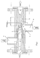
- Fig. 1 shows schematically the structure of the device according to the invention.
- Figs. 2 and 3 are diagrams in which the measurement results with those mentioned Device can be achieved, are shown graphically.
- Laval nozzle 1 with a Laval nozzle is designated, the convergent part 2 an opening angle ⁇ of about 25 - 60 ° and their divergent part 3 an opening angle ⁇ of about 3 - 20 °.
- This Laval nozzle 1 is a mixing nozzle 4 from convergent and cylindrical areas downstream, the convergent area ⁇ a Has angles of about 15 to 30 °.
- the length L1 of the cylindrical area is about 1 to 3 times its diameter. In this convergent area the diverging part of the Laval nozzle 1 projects into it, between the end of the Laval nozzle and the inner wall of the mixing nozzle a gap 5 is left open which mixes the liquid supplied via line 6 with the vapor becomes.
- a parallel flow part 8 to which a parallel flow part 9 of a diffuser 10 is connected downstream.
- the length L2 of the parallel flow part 9 is approximately 1 to 5 times its inner diameter D2.
- the opening angle of the divergent areas the diffuser 10 is approximately 15-45 °.
- the gap 11 is connected to an annular space 12, via which an Line 13 secondary liquid can be introduced into the flowing gas / liquid mixture is.
- these steps are triggered by that the steam passes through the Laval nozzle, the mixing nozzle and the diffuser.
- the steam in the Laval nozzle is accelerated to supersonic speed, wherein in the supersonic portion of the nozzle, the steam is released to a pressure that is less than atmospheric pressure.
- the over the outer contour of the Laval nozzle in the liquid sucked in the mixing nozzle mixes with the steam and it is created a homogeneous mixture of vapor and liquid that has a much lower speed of sound has as pure liquid or pure vapor (see "Guide through the Fluid Dynamics ", 8th edition, Friedrich Viehweg & Sohn 1984, pages 390 - 395).
- the mixture remains at supersonic speed. It is created in the gap between the mixing nozzle and the diffuser as a result of the acceleration of flow, a pressure that is less than atmospheric Pressure is.
- a throttle valve At the outlet of the diffuser is a throttle valve, not shown creates a back pressure, which is slowly increased until a vertical shock in the parallel flow part 9 of the diffuser, in which the Steam condensed completely via the shock. That leads to the desired one Pressure increase in the flow.
- a secondary flow is created via the gap 11 between the mixing nozzle and the diffuser introduced from liquid into the condensation zone before the compression shock, which further accelerates the condensation process and increases the pressure.
- the condensation process is completely completed with the shock.
- the condensation of the steam is associated with thermal energy, about 600 cal / g become free.
- the heat is derived from the liquid flowing out of the diffuser added.
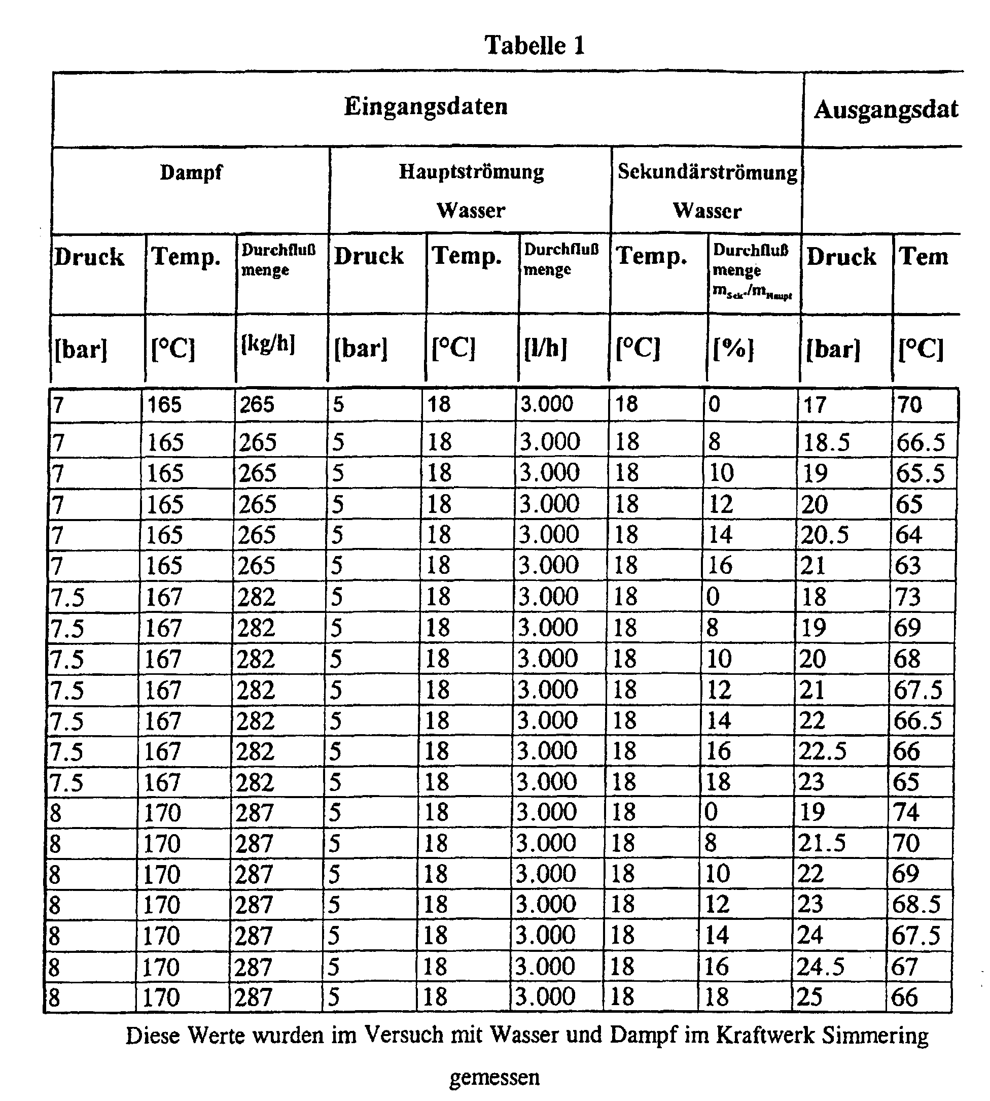
- Table 1 The data in Table 1 are graphical in the diagram connected as FIG. 2 played. This diagram clearly shows the increase in pressure as a result added secondary liquid is recognizable. When using 7 bar, 7.5 bar or 8 bar steam pressure, the pressure in the flowing liquid rises from 17 bar up to 21 bar at 16%, from 18 to 23 bar at 18% and from 19 to 25 bar with 18% addition of secondary fluid.
Landscapes
- Chemical & Material Sciences (AREA)
- Chemical Kinetics & Catalysis (AREA)
- Jet Pumps And Other Pumps (AREA)
- Organic Low-Molecular-Weight Compounds And Preparation Thereof (AREA)
- Nozzles (AREA)
Abstract
Description
Claims (3)
- Verfahren zur Erhöhung des Druckes bzw. Steigerung der Enthalpie eines mit Überschall strömenden Fluids, wobei Dampf mit Flüssigkeit vermischt und dieses Gemisch auf Überschallgeschwindigkeit beschleunigt wird, wonach dann ein Kondensationsstoß ausgelöst wird, dadurch gekennzeichnet, daß vor Auslösung des Kondensationsstoßes zusätzlich Flüssigkeit in das mit Überschallgeschwindigkeit strömende Gemisch eingebracht wird.
- Verfahren nach Anspruch 1, dadurch gekennzeichnet, daß die Zufuhr der zusätzlichen Flüssigkeit durch den durch das strömende Gemisch erzeugten Unterdruck bewirkt wird.
- Vorrichtung zur Durchführung des Verfahrens nach Anspruch 1 oder 2, bei welcher eine Dampfbeschleunigungsdüse, ein Zufuhrspalt für ein flüssiges Medium, eine konvergierende Mischdüse und ein Diffusor vorgesehen ist, wobei zwischen Mischdüse und Diffusor ein Parallelströmungsabschnitt angeordnet ist, in dem ein den Parallelströmungsabschnitt teilender Spalt angeordnet ist, dadurch gekennzeichnet, daß die in Strömungsrichtung gemessene Länge (B) des Spaltes zwischen dem 0,5 und 0,9-fachen des Durchmessers (D1) des Parallelströmungsabschnittes (8) beträgt.
Priority Applications (1)
| Application Number | Priority Date | Filing Date | Title |
|---|---|---|---|
| AT99930911T ATE234145T1 (de) | 1998-07-08 | 1999-07-07 | Verfahren und vorrichtung zur erhöhung des druckes beziehungsweise steigerung der enthalpie eines mit überschall strömenden fluids |
Applications Claiming Priority (3)
| Application Number | Priority Date | Filing Date | Title |
|---|---|---|---|
| AT118698 | 1998-07-08 | ||
| AT118698 | 1998-07-08 | ||
| PCT/AT1999/000173 WO2000002653A1 (de) | 1998-07-08 | 1999-07-07 | Verfahren und vorrichtung zur erhöhung des druckes beziehungsweise steigerung der enthalpie eines mit überschall strömenden fluids |
Publications (2)
| Publication Number | Publication Date |
|---|---|
| EP1034029A1 EP1034029A1 (de) | 2000-09-13 |
| EP1034029B1 true EP1034029B1 (de) | 2003-03-12 |
Family
ID=3508473
Family Applications (1)
| Application Number | Title | Priority Date | Filing Date |
|---|---|---|---|
| EP99930911A Expired - Lifetime EP1034029B1 (de) | 1998-07-08 | 1999-07-07 | Verfahren und vorrichtung zur erhöhung des druckes beziehungsweise steigerung der enthalpie eines mit überschall strömenden fluids |
Country Status (5)
| Country | Link |
|---|---|
| US (1) | US6523991B1 (de) |
| EP (1) | EP1034029B1 (de) |
| CA (1) | CA2302648A1 (de) |
| DE (1) | DE59904529D1 (de) |
| WO (1) | WO2000002653A1 (de) |
Cited By (5)
| Publication number | Priority date | Publication date | Assignee | Title |
|---|---|---|---|---|
| US8193395B2 (en) | 2007-05-02 | 2012-06-05 | Pursuit Dynamics Plc | Biomass treatment process and system |
| US8419378B2 (en) | 2004-07-29 | 2013-04-16 | Pursuit Dynamics Plc | Jet pump |
| US8789769B2 (en) | 2006-09-15 | 2014-07-29 | Tyco Fire & Security Gmbh | Mist generating apparatus and method |
| US9004375B2 (en) | 2004-02-26 | 2015-04-14 | Tyco Fire & Security Gmbh | Method and apparatus for generating a mist |
| US9010663B2 (en) | 2004-02-26 | 2015-04-21 | Tyco Fire & Security Gmbh | Method and apparatus for generating a mist |
Families Citing this family (44)
| Publication number | Priority date | Publication date | Assignee | Title |
|---|---|---|---|---|
| US6623154B1 (en) * | 2000-04-12 | 2003-09-23 | Premier Wastewater International, Inc. | Differential injector |
| US7416326B2 (en) * | 2002-05-10 | 2008-08-26 | Family-Life Co., Ltd. | Apparatus for producing sterilized water |
| CA2391757C (en) * | 2002-06-26 | 2004-07-20 | Per Westergaard | Burner fuel mixer head for concurrently burning two gaseous fuels |
| EP1549856B1 (de) * | 2002-10-11 | 2007-06-13 | Pursuit Dynamics PLC. | Strahlpumpe |
| GB0303470D0 (en) * | 2003-02-14 | 2003-03-19 | Malvern Instr Ltd | Dilution system and method |
| US20050061378A1 (en) * | 2003-08-01 | 2005-03-24 | Foret Todd L. | Multi-stage eductor apparatus |
| US7025883B1 (en) * | 2003-09-30 | 2006-04-11 | Ok Technologies, Llc | Autotrofic sulfur denitration chamber and calcium reactor |
| CA2540712A1 (en) * | 2003-10-03 | 2005-04-14 | O.K. Technologies, Llc | Waste water treatment system and process |
| US6974279B2 (en) * | 2003-10-07 | 2005-12-13 | Trinity Inudstrial Corporation | Ejector, fine solid piece recovery apparatus and fluid conveyor |
| US20080103217A1 (en) | 2006-10-31 | 2008-05-01 | Hari Babu Sunkara | Polyether ester elastomer composition |
| EP2108255A3 (de) * | 2004-05-11 | 2011-04-13 | O.K. Technologies, LLC | System zum Züchten von Wassertieren |
| US20100129888A1 (en) * | 2004-07-29 | 2010-05-27 | Jens Havn Thorup | Liquefaction of starch-based biomass |
| WO2006061020A1 (en) * | 2004-12-08 | 2006-06-15 | Danfoss A/S | Bubble-tolerant micro-mixers |
| US20060225766A1 (en) * | 2005-03-31 | 2006-10-12 | Iderstine Richard V | Portable oral hygiene system |
| DE102006045088A1 (de) * | 2006-09-21 | 2008-03-27 | Basf Ag | Verfahren zum Durchmischen einer in einem im wesentlichen abgeschlossenen Behälter befindlichen Flüssigkeit oder Mischung aus einer Flüssigkeit und einem feinteiligen Feststoff |
| US20080277264A1 (en) * | 2007-05-10 | 2008-11-13 | Fluid-Quip, Inc. | Alcohol production using hydraulic cavitation |
| GB0710663D0 (en) * | 2007-06-04 | 2007-07-11 | Pursuit Dynamics Plc | An improved mist generating apparatus and method |
| AU2008307630A1 (en) * | 2007-09-28 | 2009-04-09 | Xiom Corporation | Multiple stage flow amplification and mixing system |
| US7784999B1 (en) * | 2009-07-01 | 2010-08-31 | Vortex Systems (International) Ci | Eductor apparatus with lobes for optimizing flow patterns |
| RU2422193C2 (ru) * | 2009-09-30 | 2011-06-27 | Фисоник Холдинг Лимитед | Устройство для приготовления водотопливной эмульсии |
| EP2519341B1 (de) * | 2009-12-29 | 2018-01-03 | Indian Oil Corporation Limited | Sprühdüsenanordnung und verfahren zur zerstäubung einer kohlenwasserstoff-flüssigkeit |
| GB201002666D0 (en) * | 2010-02-17 | 2010-04-07 | Pursuit Dynamics Plc | Apparatus and method for entraining fluids |
| WO2012015742A2 (en) * | 2010-07-30 | 2012-02-02 | Hudson Fisonic Corporation | An apparatus and method for utilizing thermal energy |
| US10184229B2 (en) | 2010-07-30 | 2019-01-22 | Robert Kremer | Apparatus, system and method for utilizing thermal energy |
| US9057484B2 (en) * | 2010-08-11 | 2015-06-16 | Huguenot Laboratories | Bypass feeder device |
| WO2012112774A1 (en) * | 2011-02-16 | 2012-08-23 | Casper Thomas J | Venturi device and method |
| DE102011106387A1 (de) * | 2011-07-04 | 2013-01-10 | Reiflock Abwassertechnik Gmbh | Verfahren zur Behandlung von Klärschlamm |
| USD778667S1 (en) | 2012-02-16 | 2017-02-14 | Thomas J Casper | Venturi device |
| DE102012025027A1 (de) * | 2012-12-20 | 2014-06-26 | Reiflock Abwassertechnik Gmbh | Vorrichtung und Verfahren zur Behandlung von Biomasse |
| US9382922B2 (en) * | 2013-01-11 | 2016-07-05 | Alstom Technology Ltd | Eductor pump and replaceable wear inserts and nozzles for use therewith |
| US9956532B2 (en) * | 2013-11-07 | 2018-05-01 | U.S. Department Of Energy | Apparatus and method for generating swirling flow |
| AU2015284297B2 (en) * | 2014-06-30 | 2020-02-20 | Robert Kremer | An apparatus, system and method for utilizing thermal energy |
| US20160039400A1 (en) * | 2014-08-08 | 2016-02-11 | Ford Global Technologies, Llc | Multi-passageway aspirator |
| US10029218B2 (en) * | 2015-01-21 | 2018-07-24 | General Electric Company | Method and system for a short length jet pump with improved mixing |
| CN105923403B (zh) * | 2016-06-24 | 2018-09-25 | 湖南慧峰环保科技开发有限公司 | 一种节能型气封式气力输送泵的使用方法 |
| CN106195347B (zh) * | 2016-07-11 | 2018-12-04 | 常州大学 | 一种设有储液器的防冰堵的自动注液节流阀 |
| CN107252641A (zh) * | 2017-07-18 | 2017-10-17 | 南通科达化工机械制造有限公司 | 一种t型气液混合器 |
| GB2590654B (en) * | 2019-12-23 | 2022-10-26 | Thermal Impact Group Ltd | Steam trap |
| JP6748867B1 (ja) * | 2020-04-21 | 2020-09-02 | 国立大学法人東京工業大学 | 混合ノズル及び混合ノズルを用いる汚染気体浄化装置 |
| US11753179B2 (en) | 2020-10-14 | 2023-09-12 | General Electric Company | Aircraft engines with a fuel cell |
| US11931199B2 (en) * | 2021-01-28 | 2024-03-19 | Yuri Abramov | Nozzles for amplifying and suppression of sound |
| US20220282739A1 (en) * | 2021-03-05 | 2022-09-08 | Honeywell International Inc. | Mixture entrainment device |
| US20230130972A1 (en) * | 2021-10-25 | 2023-04-27 | Joseph Baptiste Ferary, Iv | Inline Solids Conditioner and Pre-Wetter |
| CN118934759B (zh) * | 2024-08-08 | 2025-09-19 | 武汉安耐捷科技工程有限公司 | 一种大流量真空发生器 |
Family Cites Families (14)
| Publication number | Priority date | Publication date | Assignee | Title |
|---|---|---|---|---|
| US1195915A (en) * | 1916-08-22 | Steam-jet | ||
| GB802691A (en) * | 1955-10-26 | 1958-10-08 | Gaskell & Chambers Ltd | Liquids mixing device |
| BE764407A (fr) * | 1971-03-17 | 1971-08-16 | Four Industriel Belge | Dispositif pour le dosage d'un melange de deux gaz. |
| US4030969A (en) * | 1972-06-13 | 1977-06-21 | Defibrator Ab | Method of dispersing a bleaching agent into a stream of fibrous cellulosic pulp material in a throttling nozzle |
| US4210166A (en) * | 1977-09-14 | 1980-07-01 | Munie Julius C | Mixing apparatus |
| EP0150171B1 (de) | 1984-01-16 | 1988-12-28 | Ernst Dipl.-Ing. Braun | Verfahren zur Begasung eines Gas-Flüssigkeit-Gemisches |
| SU1308370A1 (ru) * | 1985-07-10 | 1987-05-07 | Московский филиал Всесоюзного научно-исследовательского института жиров | Струйный смеситель-реактор |
| US5171090A (en) * | 1990-04-30 | 1992-12-15 | Wiemers Reginald A | Device and method for dispensing a substance in a liquid |
| CA2050624C (en) | 1990-09-06 | 1996-06-04 | Vladimir Vladimirowitsch Fissenko | Method and device for acting upon fluids by means of a shock wave |
| US5338113A (en) | 1990-09-06 | 1994-08-16 | Transsonic Uberschall-Anlagen Gmbh | Method and device for pressure jumps in two-phase mixtures |
| US5061406A (en) * | 1990-09-25 | 1991-10-29 | Union Carbide Industrial Gases Technology Corporation | In-line gas/liquid dispersion |
| CA2129901A1 (en) | 1992-02-11 | 1993-09-02 | Efim Fuks | A two-phase supersonic flow system |
| EP0555498A1 (de) * | 1992-02-11 | 1993-08-18 | April Dynamics Industries 1990 Ltd. | Zweiphasiges Ultraschall-Strömungssystem |
| FI98892C (fi) * | 1994-11-15 | 1997-09-10 | Turun Asennusteam Oy | Polymeerien liuotusmenetelmä ja -laite |
-
1999
- 1999-07-07 CA CA002302648A patent/CA2302648A1/en not_active Abandoned
- 1999-07-07 WO PCT/AT1999/000173 patent/WO2000002653A1/de not_active Ceased
- 1999-07-07 DE DE59904529T patent/DE59904529D1/de not_active Expired - Lifetime
- 1999-07-07 EP EP99930911A patent/EP1034029B1/de not_active Expired - Lifetime
- 1999-07-07 US US09/508,218 patent/US6523991B1/en not_active Expired - Fee Related
Cited By (8)
| Publication number | Priority date | Publication date | Assignee | Title |
|---|---|---|---|---|
| US9004375B2 (en) | 2004-02-26 | 2015-04-14 | Tyco Fire & Security Gmbh | Method and apparatus for generating a mist |
| US9010663B2 (en) | 2004-02-26 | 2015-04-21 | Tyco Fire & Security Gmbh | Method and apparatus for generating a mist |
| US8419378B2 (en) | 2004-07-29 | 2013-04-16 | Pursuit Dynamics Plc | Jet pump |
| US9239063B2 (en) | 2004-07-29 | 2016-01-19 | Pursuit Marine Drive Limited | Jet pump |
| US8789769B2 (en) | 2006-09-15 | 2014-07-29 | Tyco Fire & Security Gmbh | Mist generating apparatus and method |
| US9931648B2 (en) | 2006-09-15 | 2018-04-03 | Tyco Fire & Security Gmbh | Mist generating apparatus and method |
| US8193395B2 (en) | 2007-05-02 | 2012-06-05 | Pursuit Dynamics Plc | Biomass treatment process and system |
| US8513004B2 (en) | 2007-05-02 | 2013-08-20 | Pursuit Dynamics Plc | Biomass treatment process |
Also Published As
| Publication number | Publication date |
|---|---|
| US6523991B1 (en) | 2003-02-25 |
| WO2000002653A1 (de) | 2000-01-20 |
| CA2302648A1 (en) | 2000-01-20 |
| EP1034029A1 (de) | 2000-09-13 |
| DE59904529D1 (de) | 2003-04-17 |
Similar Documents
| Publication | Publication Date | Title |
|---|---|---|
| EP1034029B1 (de) | Verfahren und vorrichtung zur erhöhung des druckes beziehungsweise steigerung der enthalpie eines mit überschall strömenden fluids | |
| DE970090C (de) | Rueckstossduese fuer Rueckstosstriebwerke | |
| DE69915098T2 (de) | Verfahren und Vorrichtung zur Verflüssigung eines Gases | |
| DE19536837B4 (de) | Vorrichtung und Verfahren zum Einspritzen von Brennstoffen in komprimierte gasförmige Medien | |
| DE2159490A1 (de) | Abgasanlage für einen Verbrennungsmotor sowie Verfahren zur Verringerung des Gegendruckes der Abgase | |
| DE3922445A1 (de) | Verfahren und kompressionsrohr zur erhoehung des druckes eines stroemenden gasfoermigen mittels sowie kraftmaschine mit verwendung des kompressionsrohrs | |
| DE1155941B (de) | Triebwerk | |
| EP3953588B1 (de) | Strahlpumpe | |
| DE10150931A1 (de) | Verbesserte Gemischbildung in Verbrennungskraftmaschinen | |
| DE2031016A1 (de) | Vorrichtung zum Mischen von Flussig keit und Gas | |
| CH212269A (de) | Gasturbinenanlage. | |
| DE850969C (de) | Brennkammer, insbesondere fuer Strahltriebwerke | |
| EP0150171B1 (de) | Verfahren zur Begasung eines Gas-Flüssigkeit-Gemisches | |
| DE1120181B (de) | Windkanal | |
| DE102009046992A1 (de) | Abgasturbolader sowie Brennkraftmaschine | |
| CH684055A5 (de) | Werferrohr mit einer Zumischeinrichtung zum Erzeugen eines Flüssigkeits-Gemischstrahles. | |
| DE941103C (de) | Energierueckgewinnungsvorrichtung fuer eine Gruppe von intermittierenden Strahltriebwerken mit Rueckstroemdrossel | |
| DE1209773B (de) | Verfahren zum Erzeugen von Stroemungen hoher Machzahlen | |
| DE2025399C3 (de) | ||
| DE969978C (de) | Einrichtung, um einen Treibstrahl, insbesondere fuer Luftfahrzeuge, in radialer Richtung zu erweitern | |
| DE897201C (de) | Verfahren und Einrichtung zur Foerderung von Kessel- oder Speisewasser mittels Strahlpumpen | |
| DE958330C (de) | Verfahren und Vorrichtung zur Abscheidung von Fluessigkeiten aus Gasen mittels Prallflaechenabscheidern | |
| DE768104C (de) | Vorrichtung mit drehbarem Brennstoffbehaelter zur Brennstoffeinspritzung in einen Luftstrom veraenderlicher Geschwindigkeit | |
| DE1053875B (de) | Rueckstossantrieb | |
| DE10050697A1 (de) | Verfahren und Vorrichtung zur isothermen Kompression eines gasförmigen Mediums |
Legal Events
| Date | Code | Title | Description |
|---|---|---|---|
| PUAI | Public reference made under article 153(3) epc to a published international application that has entered the european phase |
Free format text: ORIGINAL CODE: 0009012 |
|
| 17P | Request for examination filed |
Effective date: 20000720 |
|
| AK | Designated contracting states |
Kind code of ref document: A1 Designated state(s): AT BE CH CY DE DK ES FI FR GB GR IE IT LI LU MC NL PT SE |
|
| GRAH | Despatch of communication of intention to grant a patent |
Free format text: ORIGINAL CODE: EPIDOS IGRA |
|
| GRAH | Despatch of communication of intention to grant a patent |
Free format text: ORIGINAL CODE: EPIDOS IGRA |
|
| GRAA | (expected) grant |
Free format text: ORIGINAL CODE: 0009210 |
|
| AK | Designated contracting states |
Designated state(s): AT BE CH CY DE DK ES FI FR GB GR IE IT LI LU MC NL PT SE |
|
| PG25 | Lapsed in a contracting state [announced via postgrant information from national office to epo] |
Ref country code: NL Free format text: LAPSE BECAUSE OF FAILURE TO SUBMIT A TRANSLATION OF THE DESCRIPTION OR TO PAY THE FEE WITHIN THE PRESCRIBED TIME-LIMIT Effective date: 20030312 Ref country code: IT Free format text: LAPSE BECAUSE OF FAILURE TO SUBMIT A TRANSLATION OF THE DESCRIPTION OR TO PAY THE FEE WITHIN THE PRESCRIBED TIME-LIMIT;WARNING: LAPSES OF ITALIAN PATENTS WITH EFFECTIVE DATE BEFORE 2007 MAY HAVE OCCURRED AT ANY TIME BEFORE 2007. THE CORRECT EFFECTIVE DATE MAY BE DIFFERENT FROM THE ONE RECORDED. Effective date: 20030312 Ref country code: IE Free format text: LAPSE BECAUSE OF FAILURE TO SUBMIT A TRANSLATION OF THE DESCRIPTION OR TO PAY THE FEE WITHIN THE PRESCRIBED TIME-LIMIT Effective date: 20030312 Ref country code: GR Free format text: LAPSE BECAUSE OF FAILURE TO SUBMIT A TRANSLATION OF THE DESCRIPTION OR TO PAY THE FEE WITHIN THE PRESCRIBED TIME-LIMIT Effective date: 20030312 Ref country code: GB Free format text: LAPSE BECAUSE OF FAILURE TO SUBMIT A TRANSLATION OF THE DESCRIPTION OR TO PAY THE FEE WITHIN THE PRESCRIBED TIME-LIMIT Effective date: 20030312 Ref country code: FR Free format text: LAPSE BECAUSE OF FAILURE TO SUBMIT A TRANSLATION OF THE DESCRIPTION OR TO PAY THE FEE WITHIN THE PRESCRIBED TIME-LIMIT Effective date: 20030312 Ref country code: FI Free format text: LAPSE BECAUSE OF FAILURE TO SUBMIT A TRANSLATION OF THE DESCRIPTION OR TO PAY THE FEE WITHIN THE PRESCRIBED TIME-LIMIT Effective date: 20030312 |
|
| REG | Reference to a national code |
Ref country code: GB Ref legal event code: FG4D Free format text: NOT ENGLISH |
|
| REG | Reference to a national code |
Ref country code: CH Ref legal event code: EP |
|
| REG | Reference to a national code |
Ref country code: IE Ref legal event code: FG4D Free format text: GERMAN |
|
| REF | Corresponds to: |
Ref document number: 59904529 Country of ref document: DE Date of ref document: 20030417 Kind code of ref document: P |
|
| PG25 | Lapsed in a contracting state [announced via postgrant information from national office to epo] |
Ref country code: SE Free format text: LAPSE BECAUSE OF FAILURE TO SUBMIT A TRANSLATION OF THE DESCRIPTION OR TO PAY THE FEE WITHIN THE PRESCRIBED TIME-LIMIT Effective date: 20030612 Ref country code: DK Free format text: LAPSE BECAUSE OF FAILURE TO SUBMIT A TRANSLATION OF THE DESCRIPTION OR TO PAY THE FEE WITHIN THE PRESCRIBED TIME-LIMIT Effective date: 20030612 |
|
| PG25 | Lapsed in a contracting state [announced via postgrant information from national office to epo] |
Ref country code: PT Free format text: LAPSE BECAUSE OF FAILURE TO SUBMIT A TRANSLATION OF THE DESCRIPTION OR TO PAY THE FEE WITHIN THE PRESCRIBED TIME-LIMIT Effective date: 20030616 |
|
| PG25 | Lapsed in a contracting state [announced via postgrant information from national office to epo] |
Ref country code: LU Free format text: LAPSE BECAUSE OF NON-PAYMENT OF DUE FEES Effective date: 20030707 Ref country code: CY Free format text: LAPSE BECAUSE OF FAILURE TO SUBMIT A TRANSLATION OF THE DESCRIPTION OR TO PAY THE FEE WITHIN THE PRESCRIBED TIME-LIMIT Effective date: 20030707 |
|
| PG25 | Lapsed in a contracting state [announced via postgrant information from national office to epo] |
Ref country code: MC Free format text: LAPSE BECAUSE OF NON-PAYMENT OF DUE FEES Effective date: 20030731 Ref country code: BE Free format text: LAPSE BECAUSE OF NON-PAYMENT OF DUE FEES Effective date: 20030731 |
|
| NLV1 | Nl: lapsed or annulled due to failure to fulfill the requirements of art. 29p and 29m of the patents act | ||
| REG | Reference to a national code |
Ref country code: CH Ref legal event code: PUE Owner name: JABER MAKLAD Free format text: NOVAFLUID - INNOVATIVE STROEMUNGS- & WAERMEUEBERTRAGUNGS-TECHNOLOGIE GMBH#THENNEBERG 231#2571 ALTENMARKT (AT) -TRANSFER TO- JABER MAKLAD#ANDERGASSE 54#1170 WIEN (AT) Ref country code: CH Ref legal event code: NV Representative=s name: PATENTANWAELTE FELDMANN & PARTNER AG |
|
| GBV | Gb: ep patent (uk) treated as always having been void in accordance with gb section 77(7)/1977 [no translation filed] |
Effective date: 20030312 |
|
| PG25 | Lapsed in a contracting state [announced via postgrant information from national office to epo] |
Ref country code: ES Free format text: LAPSE BECAUSE OF FAILURE TO SUBMIT A TRANSLATION OF THE DESCRIPTION OR TO PAY THE FEE WITHIN THE PRESCRIBED TIME-LIMIT Effective date: 20030930 |
|
| REG | Reference to a national code |
Ref country code: IE Ref legal event code: FD4D Ref document number: 1034029E Country of ref document: IE |
|
| PLBE | No opposition filed within time limit |
Free format text: ORIGINAL CODE: 0009261 |
|
| STAA | Information on the status of an ep patent application or granted ep patent |
Free format text: STATUS: NO OPPOSITION FILED WITHIN TIME LIMIT |
|
| BERE | Be: lapsed |
Owner name: *NOVAFLUID - INNOVATIVE STROMUNGS- & WARMEUBERTRAG Effective date: 20030731 |
|
| EN | Fr: translation not filed | ||
| 26N | No opposition filed |
Effective date: 20031215 |
|
| REG | Reference to a national code |
Ref country code: CH Ref legal event code: PFA Owner name: JABER MAKLAD Free format text: JABER MAKLAD#ANDERGASSE 54#1170 WIEN (AT) -TRANSFER TO- JABER MAKLAD#ANDERGASSE 54#1170 WIEN (AT) |
|
| PGFP | Annual fee paid to national office [announced via postgrant information from national office to epo] |
Ref country code: DE Payment date: 20100927 Year of fee payment: 12 |
|
| PGFP | Annual fee paid to national office [announced via postgrant information from national office to epo] |
Ref country code: AT Payment date: 20110728 Year of fee payment: 13 |
|
| PGFP | Annual fee paid to national office [announced via postgrant information from national office to epo] |
Ref country code: CH Payment date: 20111026 Year of fee payment: 13 |
|
| REG | Reference to a national code |
Ref country code: CH Ref legal event code: PL |
|
| REG | Reference to a national code |
Ref country code: AT Ref legal event code: MM01 Ref document number: 234145 Country of ref document: AT Kind code of ref document: T Effective date: 20120707 |
|
| PG25 | Lapsed in a contracting state [announced via postgrant information from national office to epo] |
Ref country code: CH Free format text: LAPSE BECAUSE OF NON-PAYMENT OF DUE FEES Effective date: 20120731 Ref country code: LI Free format text: LAPSE BECAUSE OF NON-PAYMENT OF DUE FEES Effective date: 20120731 Ref country code: DE Free format text: LAPSE BECAUSE OF NON-PAYMENT OF DUE FEES Effective date: 20130201 |
|
| PG25 | Lapsed in a contracting state [announced via postgrant information from national office to epo] |
Ref country code: AT Free format text: LAPSE BECAUSE OF NON-PAYMENT OF DUE FEES Effective date: 20120707 |
|
| REG | Reference to a national code |
Ref country code: DE Ref legal event code: R119 Ref document number: 59904529 Country of ref document: DE Effective date: 20130201 |