EP1034029B1 - Method and device for increasing the pressure or enthalpy of a fluid flowing at supersonic speed - Google Patents
Method and device for increasing the pressure or enthalpy of a fluid flowing at supersonic speed Download PDFInfo
- Publication number
- EP1034029B1 EP1034029B1 EP99930911A EP99930911A EP1034029B1 EP 1034029 B1 EP1034029 B1 EP 1034029B1 EP 99930911 A EP99930911 A EP 99930911A EP 99930911 A EP99930911 A EP 99930911A EP 1034029 B1 EP1034029 B1 EP 1034029B1
- Authority
- EP
- European Patent Office
- Prior art keywords
- pressure
- supersonic speed
- liquid
- steam
- fluid
- Prior art date
- Legal status (The legal status is an assumption and is not a legal conclusion. Google has not performed a legal analysis and makes no representation as to the accuracy of the status listed.)
- Expired - Lifetime
Links
Images

Classifications
-
- B—PERFORMING OPERATIONS; TRANSPORTING
- B01—PHYSICAL OR CHEMICAL PROCESSES OR APPARATUS IN GENERAL
- B01F—MIXING, e.g. DISSOLVING, EMULSIFYING OR DISPERSING
- B01F25/00—Flow mixers; Mixers for falling materials, e.g. solid particles
- B01F25/30—Injector mixers
- B01F25/31—Injector mixers in conduits or tubes through which the main component flows
- B01F25/312—Injector mixers in conduits or tubes through which the main component flows with Venturi elements; Details thereof
- B01F25/3123—Injector mixers in conduits or tubes through which the main component flows with Venturi elements; Details thereof with two or more Venturi elements
-
- B—PERFORMING OPERATIONS; TRANSPORTING
- B01—PHYSICAL OR CHEMICAL PROCESSES OR APPARATUS IN GENERAL
- B01F—MIXING, e.g. DISSOLVING, EMULSIFYING OR DISPERSING
- B01F25/00—Flow mixers; Mixers for falling materials, e.g. solid particles
- B01F25/30—Injector mixers
- B01F25/31—Injector mixers in conduits or tubes through which the main component flows
- B01F25/312—Injector mixers in conduits or tubes through which the main component flows with Venturi elements; Details thereof
- B01F25/3122—Injector mixers in conduits or tubes through which the main component flows with Venturi elements; Details thereof the material flowing at a supersonic velocity thereby creating shock waves
-
- B—PERFORMING OPERATIONS; TRANSPORTING
- B01—PHYSICAL OR CHEMICAL PROCESSES OR APPARATUS IN GENERAL
- B01F—MIXING, e.g. DISSOLVING, EMULSIFYING OR DISPERSING
- B01F25/00—Flow mixers; Mixers for falling materials, e.g. solid particles
- B01F25/30—Injector mixers
- B01F25/31—Injector mixers in conduits or tubes through which the main component flows
- B01F25/312—Injector mixers in conduits or tubes through which the main component flows with Venturi elements; Details thereof
- B01F25/3123—Injector mixers in conduits or tubes through which the main component flows with Venturi elements; Details thereof with two or more Venturi elements
- B01F25/31233—Injector mixers in conduits or tubes through which the main component flows with Venturi elements; Details thereof with two or more Venturi elements used successively
-
- B—PERFORMING OPERATIONS; TRANSPORTING
- B01—PHYSICAL OR CHEMICAL PROCESSES OR APPARATUS IN GENERAL
- B01F—MIXING, e.g. DISSOLVING, EMULSIFYING OR DISPERSING
- B01F25/00—Flow mixers; Mixers for falling materials, e.g. solid particles
- B01F25/30—Injector mixers
- B01F25/31—Injector mixers in conduits or tubes through which the main component flows
- B01F25/312—Injector mixers in conduits or tubes through which the main component flows with Venturi elements; Details thereof
- B01F25/3124—Injector mixers in conduits or tubes through which the main component flows with Venturi elements; Details thereof characterised by the place of introduction of the main flow
- B01F25/31242—Injector mixers in conduits or tubes through which the main component flows with Venturi elements; Details thereof characterised by the place of introduction of the main flow the main flow being injected in the central area of the venturi, creating an aspiration in the circumferential part of the conduit
-
- Y—GENERAL TAGGING OF NEW TECHNOLOGICAL DEVELOPMENTS; GENERAL TAGGING OF CROSS-SECTIONAL TECHNOLOGIES SPANNING OVER SEVERAL SECTIONS OF THE IPC; TECHNICAL SUBJECTS COVERED BY FORMER USPC CROSS-REFERENCE ART COLLECTIONS [XRACs] AND DIGESTS
- Y10—TECHNICAL SUBJECTS COVERED BY FORMER USPC
- Y10T—TECHNICAL SUBJECTS COVERED BY FORMER US CLASSIFICATION
- Y10T137/00—Fluid handling
- Y10T137/8593—Systems
- Y10T137/87571—Multiple inlet with single outlet
- Y10T137/87587—Combining by aspiration
- Y10T137/87595—Combining of three or more diverse fluids
-
- Y—GENERAL TAGGING OF NEW TECHNOLOGICAL DEVELOPMENTS; GENERAL TAGGING OF CROSS-SECTIONAL TECHNOLOGIES SPANNING OVER SEVERAL SECTIONS OF THE IPC; TECHNICAL SUBJECTS COVERED BY FORMER USPC CROSS-REFERENCE ART COLLECTIONS [XRACs] AND DIGESTS
- Y10—TECHNICAL SUBJECTS COVERED BY FORMER USPC
- Y10T—TECHNICAL SUBJECTS COVERED BY FORMER US CLASSIFICATION
- Y10T137/00—Fluid handling
- Y10T137/8593—Systems
- Y10T137/87571—Multiple inlet with single outlet
- Y10T137/87587—Combining by aspiration
- Y10T137/87603—Plural motivating fluid jets
Definitions
- the invention relates to a method for increasing the pressure or Increase in the enthalpy of a fluid flowing at supersonic speed, with steam mixed with liquid and this mixture to supersonic speed is accelerated, after which a condensation surge is triggered.
- compressible two-phase flows behave in such a way that the State variables - with the exception of entropy, temperature and the resting temperature - change opposite in the subsonic and supersonic range (see E.Truckenbrodt, "Fluid Mechanics", Volume 2, Springer Verlag 1980, page 68). It means e.g. the supply of heat to a supersonic flow is a delay, but to a Subsonic flow an acceleration.
- condensation surge depends on the condensing surge Amount of water vapor (see Dr. Klaus Oswatitsch: Gasdynamik; Springer Verlag 1952, page 57).
- the condensation surge occurs when a fluid flows that is oversaturated Contains water vapor, and is the result of a sudden condensation of the Steam, which takes place very quickly and in a narrow zone, which acts as a "condensation impact surface" referred to as.
- the stability of the condensation surge against small disturbances in the direction perpendicular to their surface depends on the thermodynamic Condition of the steam before the impact. This just has to correspond to the beginning of a rapid condensation of the steam. A detailed Derivation of this process can be found in L.D. Landau and E.M. Lifschitz: Hydrodynamics: Akademie publishing house, Berlin 1966.
- the mechanism of the pressure increase is that condensation
- the vapor creates vacuum spaces from the speed of sound incoming fluid are filled up suddenly.
- the resulting kinetic Energy is converted into pressure.
- the strength of the pressure increase due to the condensation depends on the temperature difference between steam and liquid or from the liquid temperature when mixed with the steam and depending on the location of the shock.
- a steam accelerating nozzle, a feed nip for a liquid medium, a converging mixing nozzle and a diffuser is provided, a parallel flow section being arranged between the mixing nozzle and the diffuser in which a gap dividing the parallel flow section is arranged the length of the gap measured in the direction of flow between the 0.5 to 0.9 times the diameter of the parallel flow section. Because of this gap size it is achieved that a sufficient amount of additional liquid automatically is sucked in without the flow of the vapor / liquid mixture affect.
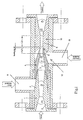
- Fig. 1 shows schematically the structure of the device according to the invention.
- Figs. 2 and 3 are diagrams in which the measurement results with those mentioned Device can be achieved, are shown graphically.
- Laval nozzle 1 with a Laval nozzle is designated, the convergent part 2 an opening angle ⁇ of about 25 - 60 ° and their divergent part 3 an opening angle ⁇ of about 3 - 20 °.
- This Laval nozzle 1 is a mixing nozzle 4 from convergent and cylindrical areas downstream, the convergent area ⁇ a Has angles of about 15 to 30 °.
- the length L1 of the cylindrical area is about 1 to 3 times its diameter. In this convergent area the diverging part of the Laval nozzle 1 projects into it, between the end of the Laval nozzle and the inner wall of the mixing nozzle a gap 5 is left open which mixes the liquid supplied via line 6 with the vapor becomes.
- a parallel flow part 8 to which a parallel flow part 9 of a diffuser 10 is connected downstream.
- the length L2 of the parallel flow part 9 is approximately 1 to 5 times its inner diameter D2.
- the opening angle of the divergent areas the diffuser 10 is approximately 15-45 °.
- the gap 11 is connected to an annular space 12, via which an Line 13 secondary liquid can be introduced into the flowing gas / liquid mixture is.
- these steps are triggered by that the steam passes through the Laval nozzle, the mixing nozzle and the diffuser.
- the steam in the Laval nozzle is accelerated to supersonic speed, wherein in the supersonic portion of the nozzle, the steam is released to a pressure that is less than atmospheric pressure.
- the over the outer contour of the Laval nozzle in the liquid sucked in the mixing nozzle mixes with the steam and it is created a homogeneous mixture of vapor and liquid that has a much lower speed of sound has as pure liquid or pure vapor (see "Guide through the Fluid Dynamics ", 8th edition, Friedrich Viehweg & Sohn 1984, pages 390 - 395).
- the mixture remains at supersonic speed. It is created in the gap between the mixing nozzle and the diffuser as a result of the acceleration of flow, a pressure that is less than atmospheric Pressure is.
- a throttle valve At the outlet of the diffuser is a throttle valve, not shown creates a back pressure, which is slowly increased until a vertical shock in the parallel flow part 9 of the diffuser, in which the Steam condensed completely via the shock. That leads to the desired one Pressure increase in the flow.
- a secondary flow is created via the gap 11 between the mixing nozzle and the diffuser introduced from liquid into the condensation zone before the compression shock, which further accelerates the condensation process and increases the pressure.
- the condensation process is completely completed with the shock.
- the condensation of the steam is associated with thermal energy, about 600 cal / g become free.
- the heat is derived from the liquid flowing out of the diffuser added.
- Table 1 The data in Table 1 are graphical in the diagram connected as FIG. 2 played. This diagram clearly shows the increase in pressure as a result added secondary liquid is recognizable. When using 7 bar, 7.5 bar or 8 bar steam pressure, the pressure in the flowing liquid rises from 17 bar up to 21 bar at 16%, from 18 to 23 bar at 18% and from 19 to 25 bar with 18% addition of secondary fluid.
Abstract
Description
Die Erfindung bezieht sich auf ein Verfahren zur Erhöhung des Druckes bzw. Steigerung der Enthalpie eines mit Überschallgeschwindigkeit strömenden Fluids, wobei Dampf mit Flüssigkeit vermischt und dieses Gemisch auf Überschallgeschwindigkeit beschleunigt wird, wonach dann ein Kondensationsstoß ausgelöst wird.The invention relates to a method for increasing the pressure or Increase in the enthalpy of a fluid flowing at supersonic speed, with steam mixed with liquid and this mixture to supersonic speed is accelerated, after which a condensation surge is triggered.
Zunächst sei einmal auf die grundlegende Problematik der strömenden Mischungen von Zweiphasengemischen, z.B. Luft/Wasser oder Dampfflüssigkeit od.dgl., eingegangen.First of all, let's look at the basic problems of flowing mixtures of two-phase mixtures, e.g. Air / water or vapor liquid or the like.
In derartigen Mischungen kann die "Schallgeschwindigkeit" kleine Werte annehmen, wobei unter "Schallgeschwindigkeit" jene Größe zu verstehen ist, welche für die Bildung der Mach'schen Zahl ausschlaggebend ist (siehe VDI-Zeitung 99, 1957, Nr. 30, 21. Oktober, "Überschallströmungen von hoher Machzahl bei kleinen Strömungsgeschwindigkeiten" von Carl Pfleiderer, Seite 1535 und 1536; und "Grundlagen für Pumpen von "em. Prof.Dipl.-Ing. W. Pohlenz, VEB Verlag Technik, Berlin 1975, Seiten 49 und 41).In such mixtures the "speed of sound" can take small values, whereby "speed of sound" is to be understood as the size which is decisive for the formation of the Mach number (see VDI-Zeitung 99, 1957, No. 30, October 21, "Supersonic flows of high Mach number with small Flow velocities "by Carl Pfleiderer, pages 1535 and 1536; and "Basics for pumps from" em. Prof.Dipl.-Ing. W. Pohlenz, VEB Verlag Technik, Berlin 1975, pages 49 and 41).
Auch Ostwatitsch weist darauf hin, daß in Schaumströmungen bei "Überschallgeschwindigkeiten" alle Erscheinungen auftreten, die aus einphasiger Überschallströmung bekannt sind (siehe "Gasdynamik", Dr. Klaus Ostwatitsch, Wien, Springer Verlag 1952, Seite 440). Die Analogie zwischen Zweiphasenströmung und einphasiger Strömung eines kompressiblen Fluids ist vollkommen. So benötigt man zur Beschleunigung einer Zweiphasenströmung von "Unterschall"- zu "Überschallgeschwindigkeit" ebenfalls eine konvergente-divergente Düse (Lavaldüse) bzw. ist der entgegengesetzte Vorgang nur mittels eines Verdichtungsstoßes bzw. einer Reihe von Verdichtungsstößen möglich. Die Vorgänge im Verdichtungsstoß sind bei der Zweiphasenströmung ebenfalls äußerst komplex, wobei das Überraschende dabei ist, daß der Zusammenhang zwischen Stoßeintritts- und Stoßaustrittsgeschwindigkeit sowie Druckanstieg durch einen Wärmefluß vermittelt wird (siehe "Technische Fluidmechanik" von Herbert Sieglach, VDI Verlag 1982, Seiten 214 - 230, sowie W.Al-bring, "Angewandte Strömungslehre", 4. Auflage, Verlag Theodor Steinkopff, Dresden 1970, Seiten 183 - 194). Durch das Maß der Wärmemenge, die im Stoß vom Unterschall zum Überschall fließt, ist die Stoßintensität bestimmt.Ostwatitsch also points out that in foam flows at "supersonic speeds" all appearances occur from single-phase supersonic flow are known (see "Gas Dynamics", Dr. Klaus Ostwatitsch, Vienna, Springer Verlag 1952, page 440). The analogy between two-phase flow and single-phase Flow of a compressible fluid is perfect. So you need for acceleration a two-phase flow from "subsonic" to "supersonic speed" also a convergent-divergent nozzle (Laval nozzle) or is the opposite process only by means of a shock or a series of Compression shocks possible. The processes in the surge are in the two-phase flow also extremely complex, the surprising thing being that the relationship between impact entry and exit velocity as well as Pressure increase is mediated by a heat flow (see "Technical Fluid Mechanics" by Herbert Sieglach, VDI Verlag 1982, pages 214 - 230, and W.Al-bring, "Applied Fluid Mechanics", 4th edition, published by Theodor Steinkopff, Dresden 1970, pages 183-194). Due to the amount of heat generated in the impact from If the subsonic flows to the supersonic, the impact intensity is determined.
Weiters verhalten sich kompressible Zweiphasenströmungen so, daß sich die Zustandsgrößen - mit Ausnahme der Entropie, der Temperatur und der Ruhetemperatur - im Unter- und Überschallbereich entgegengesetzt verändern (siehe E.Truckenbrodt, "Fluidmechanik", Band 2, Springer Verlag 1980, Seite 68). Es bedeutet z.B. die Wärmezufuhr zu einer Überschallströmung eine Verzögerung, dagegen zu einer Unterschallströmung eine Beschleunigung.Furthermore, compressible two-phase flows behave in such a way that the State variables - with the exception of entropy, temperature and the resting temperature - change opposite in the subsonic and supersonic range (see E.Truckenbrodt, "Fluid Mechanics", Volume 2, Springer Verlag 1980, page 68). It means e.g. the supply of heat to a supersonic flow is a delay, but to a Subsonic flow an acceleration.
Die Stärke des sogenannten Kondensationsstoßes hängt dabei von der kondensierenden Wasserdampfmenge ab (sieh Dr. Klaus Oswatitsch: Gasdynamik; Springer Verlag 1952, Seite 57).The strength of the so-called condensation surge depends on the condensing surge Amount of water vapor (see Dr. Klaus Oswatitsch: Gasdynamik; Springer Verlag 1952, page 57).
Der Kondensationsstoß entsteht bei der Strömung eines Fluids, das übersättigten Wasserdampf enthält, und ist das Ergebnis einer plötzlichen Kondensation des Dampfes, welche sehr schnell und in einer schmalen Zone erfolgt, die als "Kondensationsstoßfläche" bezeichnet wird. Die Stabilität des Kondensationsstoßes gegenüber kleinen Störungen in der zu ihrer Fläche senkrechten Richtung hängt vom thermodynamischen Zustand des Dampfes vor dem Stoß ab. Dieser muß gerade eben dem Beginn einer schnellen Kondensation des Dampfes entsprechen. Eine detaillierte Herleitung dieses Vorgangs findet sich bei L.D. Landau und E.M.Lifschitz: Hydrodynamik: Akademie-Verlag, Berlin 1966.The condensation surge occurs when a fluid flows that is oversaturated Contains water vapor, and is the result of a sudden condensation of the Steam, which takes place very quickly and in a narrow zone, which acts as a "condensation impact surface" referred to as. The stability of the condensation surge against small disturbances in the direction perpendicular to their surface depends on the thermodynamic Condition of the steam before the impact. This just has to correspond to the beginning of a rapid condensation of the steam. A detailed Derivation of this process can be found in L.D. Landau and E.M. Lifschitz: Hydrodynamics: Akademie publishing house, Berlin 1966.
Der Mechanismus der Druckerhöhung liegt darin begründet, daß bei der Kondensation des Dampfes Vakuumräume entstehen, die vom mit Schallgeschwindigkeit hereinströmenden Fluid schlagartig aufgefüllt werden. Die so entstehende kinetische Energie wird in Druck umgesetzt. The mechanism of the pressure increase is that condensation The vapor creates vacuum spaces from the speed of sound incoming fluid are filled up suddenly. The resulting kinetic Energy is converted into pressure.
Die Stärke der Druckerhöhung infolge der Kondensation hängt vom Temperaturunterschied zwischen Dampf und Flüssigkeit bzw. von der Flüssigkeitstemperatur bei der Vermischung mit dem Dampf und von der Lage des Verdichtungsstoßes ab.The strength of the pressure increase due to the condensation depends on the temperature difference between steam and liquid or from the liquid temperature when mixed with the steam and depending on the location of the shock.
Bei Versuchen mit Wasser und Wasserdampf wurde nach der vollständigen Kondensation des Dampfes über dem Verdichtungstoß ein Druck gemessen, der groß genug ist, um die Vorrichtung als Förderpumpe einsetzen zu können.In experiments with water and steam, the full Condensation of the vapor over the compression shock measured a pressure that was large is enough to use the device as a feed pump.
Bei einer bekannten Ausbildung der eingangs genannten Art, wie sie beispielsweise
aus der EP 0 555 498A1 hervorgeht, wird vor der Plazierung des Kondensationsstoßes
Flüssigkeit abgezogen, um sicherzustellen, daß der Kondensationsstoß in
dem dafür vorgesehenen Bereich stattfindet. Weiters erreicht man mit der bekannten
Ausbildung, daß sich die im Diffusor weiterströmende Flüssigkeit nicht so stark
erwärmt.In a known design of the type mentioned, such as, for
Beim Erfindungsgegenstand wird nun vor Auslösung des Kondensationsstoßes, zusätzlich Flüssigkeit in das mit Überschallgeschwindigkeit strömende Gemisch eingebracht. Dadurch wird erreicht, daß sich der im Kondensationsstoß auftretende Druck weiter erhöht, da durch den höheren Flüssigkeitsgehalt, eine höhere Strömungsenergie im Dampf/Flüssigkeitsgemisch enthalten ist.In the subject matter of the invention, before the condensation surge is triggered, additional liquid is introduced into the mixture flowing at supersonic speed. This ensures that the occurring in the condensation surge Pressure increased further, because of the higher fluid content, a higher flow energy is contained in the vapor / liquid mixture.
Vorteilhafterweise kann die Zufuhr der zusätzlichen Flüssigkeit durch den durch das strömende Gemisch erzeugten Unterdruck bewirkt werden, wodurch sich zusätzliche Mittel zum Fördern der zugesetzten Flüssigkeit erübrigen.Advantageously, the supply of the additional liquid through the caused by the flowing mixture negative pressure, which causes there is no need for additional means for conveying the added liquid.
Bei einer vorteilhaften Vorrichtung zur Durchführung des erfindungsgemäßen Verfahrens, bei welcher eine Dampfbeschleunigungsdüse, ein Zufuhrspalt für ein flüssiges Medium, eine konvergierende Mischdüse und ein Diffusor vorgesehen ist, wobei zwischen Mischdüse und Diffusor ein Parallelströmungsabschnitt angeordnet ist, in dem ein den Parallelströmungsabschnitt teilender Spalt angeordnet ist, beträgt die in Strömungsrichtung gemessene Länge des Spaltes zwischen dem 0,5 bis 0,9-fachen des Durchmessers des Parallelströmungsabschnittes. Durch diese Spaltgröße wird erreicht, daß eine ausreichende Menge an zusätzlicher Flüssigkeit selbsttätig eingesaugt wird, ohne die Strömung des Dampf/Flüssigkeitsgemisches zu beeinträchtigen. In an advantageous device for performing the invention Method in which a steam accelerating nozzle, a feed nip for a liquid medium, a converging mixing nozzle and a diffuser is provided, a parallel flow section being arranged between the mixing nozzle and the diffuser in which a gap dividing the parallel flow section is arranged the length of the gap measured in the direction of flow between the 0.5 to 0.9 times the diameter of the parallel flow section. Because of this gap size it is achieved that a sufficient amount of additional liquid automatically is sucked in without the flow of the vapor / liquid mixture affect.
In der Zeichnung ist ein Ausführungsbeispiel der erfindungsgemäßen Vorrichtung dargestellt.In the drawing is an embodiment of the device according to the invention shown.
Fig. 1 zeigt schematisch den Aufbau der erfindungsgemäßen Vorrichtung.Fig. 1 shows schematically the structure of the device according to the invention.
Fig. 2 und 3 sind Diagramme, in denen die Meßergebnisse, die mit der genannten Vorrichtung erzielt werden, graphisch wiedergegeben sind.Figs. 2 and 3 are diagrams in which the measurement results with those mentioned Device can be achieved, are shown graphically.
Mit 1 ist eine Lavaldüse bezeichnet, deren konvergenter Teil 2 einen Öffnungswinkel
α von etwa 25 - 60° und deren divergenter Teil 3 einen Öffnungswinkel β
von etwa 3 - 20° aufweist. Dieser Lavaldüse 1 ist eine Mischdüse 4 aus konvergenten
und zylindrischen Bereichen nachgeschaltet, wobei der konvergente Bereich γ einen
Winkel von etwa 15 bis 30° besitzt. die Länge L1 des zylindrischen Bereiches
beträgt etwa das 1 bis 3-fache seines Durchmessers. In diesen konvergenten Bereich
ragt der divergierende Teil der Lavaldüse 1 hinein, wobei zwischen dem Ende der
Lavaldüse und der Innenwandung der Mischdüse ein Spalt 5 offengelassen ist, über
welchen die über die Leitung 6 zugeführte Flüssigkeit mit dem Dampf vermischt
wird. An den konvergenten Teil 7 der Mischdüse 4 schließt, wie schon angeführt,
ein Parallelströmungsteil 8 an, dem ein Parallelströmungsteil 9 eines Diffusors 10
nachgeschaltet ist. Die Länge L2 des Parallelströmungsteils 9 beträgt etwa das 1 bis
5-fache seines Innendurchmessers D2. Der Öffnungswinkel der divergierenden Bereiche
des Diffusors 10 beträgt etwa 15 - 45°.1 with a Laval nozzle is designated, the convergent part 2 an opening angle
α of about 25 - 60 ° and their
Zwischen dem Parallelströmungsteil 8 der Mischdüse 4 und dem Parallelströmungsteil
9 des Diffusors 10, welche Teile alle koaxial hintereinander angeordnet
sind, ist ein Spalt 11 freigelassen, dessen Spaltbreite B etwa das 0,5-fache des
Durchmessers D1 des Parallelströmungsteils 8 der Mischdüse 4 aufweist.Between the parallel flow part 8 of the mixing nozzle 4 and the parallel flow part
9 of the
Der Spalt 11 ist mit einem Ringraum 12 verbunden, über welchen über eine
Leitung 13 Sekundärflüssigkeit in das strömende Gas/Flüssigkeitsgemisch einbringbar
ist.The gap 11 is connected to an
Das Verfahren durchläuft dabei die folgenden Schritte:
Diese Schritte werden bei der erfindungsgemäßen Vorrichtung dadurch ausgelöst, daß der Dampf die Lavaldüse, die Mischdüse und den Diffusor durchläuft. Dabei wird der Dampf in der Lavaldüse auf Überschallgeschwindigkeit beschleunigt, wobei im Überschallanteil der Düse der Dampf auf einen Druck entspannt wird, der kleiner ist als der atmosphärische Druck. Die über die Außenkontur der Lavaldüse in die Mischdüse angesaugte Flüssigkeit vermischt sich mit dem Dampf und es entsteht ein homogenes Gemisch aus Dampf und Füssigkeit, das eine viel kleinere Schallgeschwindigkeit hat als reine Flüssigkeit bzw. reiner Dampf (siehe "Führer durch die Strömungslehre", 8. Auflage, Friedrich Viehweg & Sohn 1984, Seite 390 - 395). Trotz der Bremswirkung durch das Ansaugen der Flüssigkeit verbleibt das Gemisch in Überschallgeschwindigkeit. Im Spalt zwischen Mischdüse und Diffusor entsteht infolge der Strömungsbeschleunigung ein Druck, der kleiner als der atmosphärische Druck ist. Am Ausgang des Diffusors wird über ein nicht dargestelltes Drosselventil ein Gegendruck erzeugt, welcher langsam gesteigert wird, bis ein senkrechter Verdichtungsstoß im Parallelströmungsteil 9 des Diffusors entsteht, in welchem der Dampf über den Verdichtungsstoß vollständig kondensiert. Das führt zu der erwünschten Druckerhöhung in der Strömung.In the device according to the invention, these steps are triggered by that the steam passes through the Laval nozzle, the mixing nozzle and the diffuser. there the steam in the Laval nozzle is accelerated to supersonic speed, wherein in the supersonic portion of the nozzle, the steam is released to a pressure that is less than atmospheric pressure. The over the outer contour of the Laval nozzle in the liquid sucked in the mixing nozzle mixes with the steam and it is created a homogeneous mixture of vapor and liquid that has a much lower speed of sound has as pure liquid or pure vapor (see "Guide through the Fluid Dynamics ", 8th edition, Friedrich Viehweg & Sohn 1984, pages 390 - 395). Despite the braking effect caused by the liquid being sucked in, the mixture remains at supersonic speed. It is created in the gap between the mixing nozzle and the diffuser as a result of the acceleration of flow, a pressure that is less than atmospheric Pressure is. At the outlet of the diffuser is a throttle valve, not shown creates a back pressure, which is slowly increased until a vertical shock in the parallel flow part 9 of the diffuser, in which the Steam condensed completely via the shock. That leads to the desired one Pressure increase in the flow.
Über den Spalt 11 zwischen Mischdüse und Diffusor wird eine Sekundärströmung aus Flüssigkeit in die Kondensationszone vor dem Verdichtunsstoß eingeleitet, wodurch der Kondensationsvorgang weiter beschleunigt und der Druck erhöht wird. Mit dem Verdichtungsstoß wird der Kondensationsvorgang komplett abgeschlossen. Die Kondensation des Dampfes ist mit Wärmeenergie verbunden, wobei etwa 600 cal/g frei werden. Die Wärme wird von der aus dem Diffusor abströmenden Flüssigkeit aufgenommen. A secondary flow is created via the gap 11 between the mixing nozzle and the diffuser introduced from liquid into the condensation zone before the compression shock, which further accelerates the condensation process and increases the pressure. The condensation process is completely completed with the shock. The condensation of the steam is associated with thermal energy, about 600 cal / g become free. The heat is derived from the liquid flowing out of the diffuser added.
Die Größenordnung des durch die zusätzlich zugeführte Flüssigkeit erzielbaren
Druckanstieges wird anhand eines Beispiels in Tabelle 1 veranschaulicht.
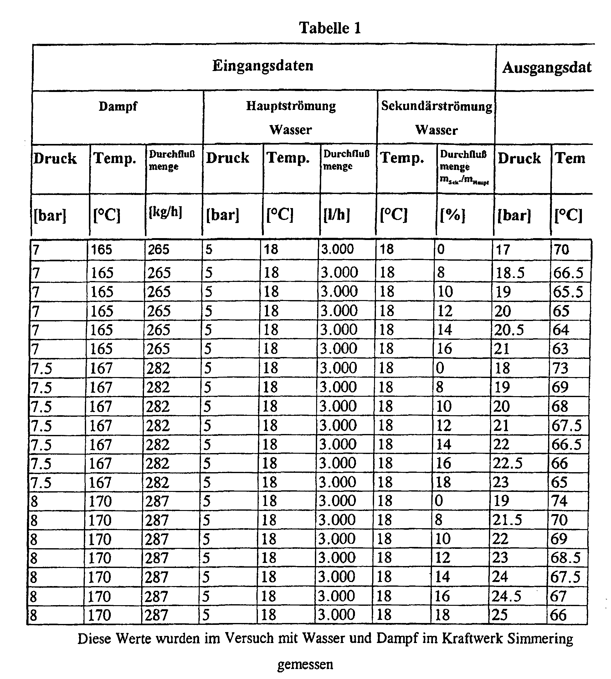
Die Daten der Tabelle 1 sind in dem als Fig. 2 angeschlossenen Diagramm graphisch wiedergegeben. Aus diesem Diagramm ist deutlich die Drucksteigerung infolge zugesetzter Sekundärflüssigkeit erkennbar. Bei der Verwendung von 7 bar, 7,5 bar, bzw. 8 bar Dampfdruck steigt der Druck in der strömenden Flüssigkeit von 17 bar bis zu 21 bar bei 16%igem, von 18 bis 23 bar bei 18%igem und von 19 bis 25 bar bei 18%igem Zusatz von Sekundärfluid.The data in Table 1 are graphical in the diagram connected as FIG. 2 played. This diagram clearly shows the increase in pressure as a result added secondary liquid is recognizable. When using 7 bar, 7.5 bar or 8 bar steam pressure, the pressure in the flowing liquid rises from 17 bar up to 21 bar at 16%, from 18 to 23 bar at 18% and from 19 to 25 bar with 18% addition of secondary fluid.
Claims (3)
- A method for elevating pressure or increasing enthalpy of a fluid flowing at supersonic speed, wherein steam is mixed with the fluid and said mixture is accelerated to supersonic speed, whereupon a condensation shock is triggered, characterized in that before triggering of the condensation shock, additional fluid is introduced into the mixture flowing at supersonic speed.
- A method according to Claim 1, wherein the introduction of the additional fluid is effected by the vacuum produced by the flowing mixture.
- A device for carrying out the method according to Claim 1 or 2, wherein a steam accelerating nozzle, a feeder gap for fluid medium, a convergence mixing nozzle and a diffuser is provided, wherein a concurrent flow segment is arranged between the mixing nozzle and the diffuser, in which a gap is disposed dividing the concurrent flow segment, characterized in that the length (B) of the gap measured in the direction of flow is between 0.5 and 0.9 times the diameter (D1) of the parallel flow segment (8).
Priority Applications (1)
| Application Number | Priority Date | Filing Date | Title |
|---|---|---|---|
| AT99930911T ATE234145T1 (en) | 1998-07-08 | 1999-07-07 | METHOD AND DEVICE FOR INCREASE THE PRESSURE OR INCREASE THE ENTHALPY OF A SUPERSONIC FLOWING FLUID |
Applications Claiming Priority (3)
| Application Number | Priority Date | Filing Date | Title |
|---|---|---|---|
| AT118698 | 1998-07-08 | ||
| AT118698 | 1998-07-08 | ||
| PCT/AT1999/000173 WO2000002653A1 (en) | 1998-07-08 | 1999-07-07 | Method and device for increasing the pressure or enthalpy of a fluid flowing at supersonic speed |
Publications (2)
| Publication Number | Publication Date |
|---|---|
| EP1034029A1 EP1034029A1 (en) | 2000-09-13 |
| EP1034029B1 true EP1034029B1 (en) | 2003-03-12 |
Family
ID=3508473
Family Applications (1)
| Application Number | Title | Priority Date | Filing Date |
|---|---|---|---|
| EP99930911A Expired - Lifetime EP1034029B1 (en) | 1998-07-08 | 1999-07-07 | Method and device for increasing the pressure or enthalpy of a fluid flowing at supersonic speed |
Country Status (5)
| Country | Link |
|---|---|
| US (1) | US6523991B1 (en) |
| EP (1) | EP1034029B1 (en) |
| CA (1) | CA2302648A1 (en) |
| DE (1) | DE59904529D1 (en) |
| WO (1) | WO2000002653A1 (en) |
Cited By (5)
| Publication number | Priority date | Publication date | Assignee | Title |
|---|---|---|---|---|
| US8193395B2 (en) | 2007-05-02 | 2012-06-05 | Pursuit Dynamics Plc | Biomass treatment process and system |
| US8419378B2 (en) | 2004-07-29 | 2013-04-16 | Pursuit Dynamics Plc | Jet pump |
| US8789769B2 (en) | 2006-09-15 | 2014-07-29 | Tyco Fire & Security Gmbh | Mist generating apparatus and method |
| US9004375B2 (en) | 2004-02-26 | 2015-04-14 | Tyco Fire & Security Gmbh | Method and apparatus for generating a mist |
| US9010663B2 (en) | 2004-02-26 | 2015-04-21 | Tyco Fire & Security Gmbh | Method and apparatus for generating a mist |
Families Citing this family (41)
| Publication number | Priority date | Publication date | Assignee | Title |
|---|---|---|---|---|
| US6623154B1 (en) * | 2000-04-12 | 2003-09-23 | Premier Wastewater International, Inc. | Differential injector |
| US7416326B2 (en) * | 2002-05-10 | 2008-08-26 | Family-Life Co., Ltd. | Apparatus for producing sterilized water |
| CA2391757C (en) * | 2002-06-26 | 2004-07-20 | Per Westergaard | Burner fuel mixer head for concurrently burning two gaseous fuels |
| AU2003274315B2 (en) * | 2002-10-11 | 2008-09-18 | Pursuit Dynamics Plc | Apparatus and Methods for Moving a Working Fluid by Contact with a Transport Fluid |
| GB0303470D0 (en) * | 2003-02-14 | 2003-03-19 | Malvern Instr Ltd | Dilution system and method |
| US20050061378A1 (en) * | 2003-08-01 | 2005-03-24 | Foret Todd L. | Multi-stage eductor apparatus |
| US7025883B1 (en) | 2003-09-30 | 2006-04-11 | Ok Technologies, Llc | Autotrofic sulfur denitration chamber and calcium reactor |
| EP1680365A2 (en) * | 2003-10-03 | 2006-07-19 | O.K. Technologies, LLC | Waste water treatment system and process |
| US6974279B2 (en) * | 2003-10-07 | 2005-12-13 | Trinity Inudstrial Corporation | Ejector, fine solid piece recovery apparatus and fluid conveyor |
| US20080103217A1 (en) * | 2006-10-31 | 2008-05-01 | Hari Babu Sunkara | Polyether ester elastomer composition |
| EP1781091A4 (en) * | 2004-05-11 | 2008-04-30 | O K Technologies Llc | System for raising aquatic animals |
| US20100129888A1 (en) * | 2004-07-29 | 2010-05-27 | Jens Havn Thorup | Liquefaction of starch-based biomass |
| EP1827668A1 (en) * | 2004-12-08 | 2007-09-05 | Danfoss A/S | Bubble-tolerant micro-mixers |
| US20060225766A1 (en) * | 2005-03-31 | 2006-10-12 | Iderstine Richard V | Portable oral hygiene system |
| DE102006045088A1 (en) * | 2006-09-21 | 2008-03-27 | Basf Ag | Mixing a liquid or suspension beneath a gas space in a closed container comprises supplying a stream of the liquid or suspension as a drive jet for a submerged ejector which aspirates gas from the gas space |
| US20080277264A1 (en) * | 2007-05-10 | 2008-11-13 | Fluid-Quip, Inc. | Alcohol production using hydraulic cavitation |
| GB0710663D0 (en) * | 2007-06-04 | 2007-07-11 | Pursuit Dynamics Plc | An improved mist generating apparatus and method |
| AU2008307630A1 (en) * | 2007-09-28 | 2009-04-09 | Xiom Corporation | Multiple stage flow amplification and mixing system |
| US7784999B1 (en) * | 2009-07-01 | 2010-08-31 | Vortex Systems (International) Ci | Eductor apparatus with lobes for optimizing flow patterns |
| RU2422193C2 (en) * | 2009-09-30 | 2011-06-27 | Фисоник Холдинг Лимитед | Device to prepare water-fuel emulsion |
| EP2519341B1 (en) * | 2009-12-29 | 2018-01-03 | Indian Oil Corporation Limited | Feed nozzle assembly and process for atomizing a hydrocarbon liquid using said nozzle assembly |
| GB201002666D0 (en) * | 2010-02-17 | 2010-04-07 | Pursuit Dynamics Plc | Apparatus and method for entraining fluids |
| WO2012015742A2 (en) * | 2010-07-30 | 2012-02-02 | Hudson Fisonic Corporation | An apparatus and method for utilizing thermal energy |
| US10184229B2 (en) | 2010-07-30 | 2019-01-22 | Robert Kremer | Apparatus, system and method for utilizing thermal energy |
| CA2827250C (en) * | 2010-08-11 | 2018-11-20 | Huguenot Laboratories | Bypass feeder device |
| US20120206993A1 (en) | 2011-02-16 | 2012-08-16 | Casper Thomas J | Venturi device and method |
| DE102011106387A1 (en) * | 2011-07-04 | 2013-01-10 | Reiflock Abwassertechnik Gmbh | Process for the treatment of sewage sludge |
| USD778667S1 (en) | 2012-02-16 | 2017-02-14 | Thomas J Casper | Venturi device |
| DE102012025027A1 (en) * | 2012-12-20 | 2014-06-26 | Reiflock Abwassertechnik Gmbh | Apparatus and method for the treatment of biomass |
| US9382922B2 (en) * | 2013-01-11 | 2016-07-05 | Alstom Technology Ltd | Eductor pump and replaceable wear inserts and nozzles for use therewith |
| US9956532B2 (en) * | 2013-11-07 | 2018-05-01 | U.S. Department Of Energy | Apparatus and method for generating swirling flow |
| CN106661875B (en) * | 2014-06-30 | 2020-02-14 | 罗伯特·克雷默 | Transonic two-phase reaction turbine |
| US20160039400A1 (en) * | 2014-08-08 | 2016-02-11 | Ford Global Technologies, Llc | Multi-passageway aspirator |
| US10029218B2 (en) * | 2015-01-21 | 2018-07-24 | General Electric Company | Method and system for a short length jet pump with improved mixing |
| CN105923403B (en) * | 2016-06-24 | 2018-09-25 | 湖南慧峰环保科技开发有限公司 | A kind of application method of energy-saving air sealed Pneumatic conveying pump |
| CN106195347B (en) * | 2016-07-11 | 2018-12-04 | 常州大学 | A kind of anti-icing stifled automatic fluid injection throttle valve equipped with liquid storage device |
| CN107252641A (en) * | 2017-07-18 | 2017-10-17 | 南通科达化工机械制造有限公司 | A kind of T-shaped air and liquid mixer |
| GB2590654B (en) * | 2019-12-23 | 2022-10-26 | Thermal Impact Group Ltd | Steam trap |
| US11753179B2 (en) | 2020-10-14 | 2023-09-12 | General Electric Company | Aircraft engines with a fuel cell |
| US11931199B2 (en) * | 2021-01-28 | 2024-03-19 | Yuri Abramov | Nozzles for amplifying and suppression of sound |
| US20220282739A1 (en) * | 2021-03-05 | 2022-09-08 | Honeywell International Inc. | Mixture entrainment device |
Family Cites Families (14)
| Publication number | Priority date | Publication date | Assignee | Title |
|---|---|---|---|---|
| US1195915A (en) * | 1916-08-22 | Steam-jet | ||
| GB802691A (en) * | 1955-10-26 | 1958-10-08 | Gaskell & Chambers Ltd | Liquids mixing device |
| BE764407A (en) * | 1971-03-17 | 1971-08-16 | Four Industriel Belge | DEVICE FOR THE DOSING OF A MIXTURE OF TWO GASES. |
| US4030969A (en) * | 1972-06-13 | 1977-06-21 | Defibrator Ab | Method of dispersing a bleaching agent into a stream of fibrous cellulosic pulp material in a throttling nozzle |
| US4210166A (en) * | 1977-09-14 | 1980-07-01 | Munie Julius C | Mixing apparatus |
| EP0150171B1 (en) * | 1984-01-16 | 1988-12-28 | Ernst Dipl.-Ing. Braun | Procedure for introducing gas into a gas-liquid mixture |
| SU1308370A1 (en) * | 1985-07-10 | 1987-05-07 | Московский филиал Всесоюзного научно-исследовательского института жиров | Jet mixer-reactor |
| US5171090A (en) * | 1990-04-30 | 1992-12-15 | Wiemers Reginald A | Device and method for dispensing a substance in a liquid |
| CA2050624C (en) * | 1990-09-06 | 1996-06-04 | Vladimir Vladimirowitsch Fissenko | Method and device for acting upon fluids by means of a shock wave |
| US5338113A (en) * | 1990-09-06 | 1994-08-16 | Transsonic Uberschall-Anlagen Gmbh | Method and device for pressure jumps in two-phase mixtures |
| US5061406A (en) * | 1990-09-25 | 1991-10-29 | Union Carbide Industrial Gases Technology Corporation | In-line gas/liquid dispersion |
| EP0555498A1 (en) * | 1992-02-11 | 1993-08-18 | April Dynamics Industries 1990 Ltd. | A two-phase supersonic flow system |
| WO1993016791A2 (en) * | 1992-02-11 | 1993-09-02 | April Dynamics Industries Ltd. | A two-phase supersonic flow system |
| FI98892C (en) * | 1994-11-15 | 1997-09-10 | Turun Asennusteam Oy | Polymer dissolution method and apparatus |
-
1999
- 1999-07-07 WO PCT/AT1999/000173 patent/WO2000002653A1/en active IP Right Grant
- 1999-07-07 DE DE59904529T patent/DE59904529D1/en not_active Expired - Lifetime
- 1999-07-07 US US09/508,218 patent/US6523991B1/en not_active Expired - Fee Related
- 1999-07-07 EP EP99930911A patent/EP1034029B1/en not_active Expired - Lifetime
- 1999-07-07 CA CA002302648A patent/CA2302648A1/en not_active Abandoned
Cited By (8)
| Publication number | Priority date | Publication date | Assignee | Title |
|---|---|---|---|---|
| US9004375B2 (en) | 2004-02-26 | 2015-04-14 | Tyco Fire & Security Gmbh | Method and apparatus for generating a mist |
| US9010663B2 (en) | 2004-02-26 | 2015-04-21 | Tyco Fire & Security Gmbh | Method and apparatus for generating a mist |
| US8419378B2 (en) | 2004-07-29 | 2013-04-16 | Pursuit Dynamics Plc | Jet pump |
| US9239063B2 (en) | 2004-07-29 | 2016-01-19 | Pursuit Marine Drive Limited | Jet pump |
| US8789769B2 (en) | 2006-09-15 | 2014-07-29 | Tyco Fire & Security Gmbh | Mist generating apparatus and method |
| US9931648B2 (en) | 2006-09-15 | 2018-04-03 | Tyco Fire & Security Gmbh | Mist generating apparatus and method |
| US8193395B2 (en) | 2007-05-02 | 2012-06-05 | Pursuit Dynamics Plc | Biomass treatment process and system |
| US8513004B2 (en) | 2007-05-02 | 2013-08-20 | Pursuit Dynamics Plc | Biomass treatment process |
Also Published As
| Publication number | Publication date |
|---|---|
| US6523991B1 (en) | 2003-02-25 |
| WO2000002653A1 (en) | 2000-01-20 |
| CA2302648A1 (en) | 2000-01-20 |
| DE59904529D1 (en) | 2003-04-17 |
| EP1034029A1 (en) | 2000-09-13 |
Similar Documents
| Publication | Publication Date | Title |
|---|---|---|
| EP1034029B1 (en) | Method and device for increasing the pressure or enthalpy of a fluid flowing at supersonic speed | |
| DE970090C (en) | Recoil nozzle for recoil engines | |
| DE69915098T2 (en) | Method and device for liquefying a gas | |
| DE19536837B4 (en) | Apparatus and method for injecting fuels into compressed gaseous media | |
| DE2159490A1 (en) | Exhaust system for an internal combustion engine and method for reducing the back pressure of the exhaust gases | |
| DE3922445A1 (en) | METHOD AND COMPRESSION TUBE FOR INCREASING THE PRESSURE OF A STROEMENDING GASOFIVE MEDIUM AND POWER MACHINE USING THE COMPRESSION TUBE | |
| DE1528909A1 (en) | Fluid propulsion system | |
| DE1155941B (en) | Engine | |
| DE2456837A1 (en) | COMBUSTION CHAMBER FOR SYSTEMS FOR FEEDING COMBUSTION ENGINES WITH PRE-COMPRESSION | |
| EP3953588B1 (en) | Jet pump | |
| DE10150931A1 (en) | Improved mixture formation in internal combustion engines | |
| DE2031016A1 (en) | Liquid gas mixer | |
| CH212269A (en) | Gas turbine plant. | |
| DE850969C (en) | Combustion chamber, especially for jet engines | |
| EP0150171B1 (en) | Procedure for introducing gas into a gas-liquid mixture | |
| DE1120181B (en) | Wind tunnel | |
| DE102009046992A1 (en) | Exhaust gas turbocharger for use in internal-combustion engine, has bypass including jet pump for producing negative pressure in vacuum pipe that is part of exhaust gas pipe arranged on low pressure side of turbine | |
| DE865558C (en) | Recoil drive | |
| DE941103C (en) | Energy recovery device for a group of intermittent jet engines with backflow throttle | |
| DE969978C (en) | Device to expand a propulsion jet, especially for aircraft, in the radial direction | |
| CH684055A5 (en) | Launcher tube with a mixing device for producing a liquid mixture jet. | |
| DE897201C (en) | Process and device for pumping boiler or feed water by means of jet pumps | |
| DE958330C (en) | Method and device for separating liquids from gases by means of baffle separators | |
| DE175129C (en) | ||
| DE768104C (en) | Device with rotatable fuel container for injecting fuel into an air stream of variable speed |
Legal Events
| Date | Code | Title | Description |
|---|---|---|---|
| PUAI | Public reference made under article 153(3) epc to a published international application that has entered the european phase |
Free format text: ORIGINAL CODE: 0009012 |
|
| 17P | Request for examination filed |
Effective date: 20000720 |
|
| AK | Designated contracting states |
Kind code of ref document: A1 Designated state(s): AT BE CH CY DE DK ES FI FR GB GR IE IT LI LU MC NL PT SE |
|
| GRAH | Despatch of communication of intention to grant a patent |
Free format text: ORIGINAL CODE: EPIDOS IGRA |
|
| GRAH | Despatch of communication of intention to grant a patent |
Free format text: ORIGINAL CODE: EPIDOS IGRA |
|
| GRAA | (expected) grant |
Free format text: ORIGINAL CODE: 0009210 |
|
| AK | Designated contracting states |
Designated state(s): AT BE CH CY DE DK ES FI FR GB GR IE IT LI LU MC NL PT SE |
|
| PG25 | Lapsed in a contracting state [announced via postgrant information from national office to epo] |
Ref country code: NL Free format text: LAPSE BECAUSE OF FAILURE TO SUBMIT A TRANSLATION OF THE DESCRIPTION OR TO PAY THE FEE WITHIN THE PRESCRIBED TIME-LIMIT Effective date: 20030312 Ref country code: IT Free format text: LAPSE BECAUSE OF FAILURE TO SUBMIT A TRANSLATION OF THE DESCRIPTION OR TO PAY THE FEE WITHIN THE PRESCRIBED TIME-LIMIT;WARNING: LAPSES OF ITALIAN PATENTS WITH EFFECTIVE DATE BEFORE 2007 MAY HAVE OCCURRED AT ANY TIME BEFORE 2007. THE CORRECT EFFECTIVE DATE MAY BE DIFFERENT FROM THE ONE RECORDED. Effective date: 20030312 Ref country code: IE Free format text: LAPSE BECAUSE OF FAILURE TO SUBMIT A TRANSLATION OF THE DESCRIPTION OR TO PAY THE FEE WITHIN THE PRESCRIBED TIME-LIMIT Effective date: 20030312 Ref country code: GR Free format text: LAPSE BECAUSE OF FAILURE TO SUBMIT A TRANSLATION OF THE DESCRIPTION OR TO PAY THE FEE WITHIN THE PRESCRIBED TIME-LIMIT Effective date: 20030312 Ref country code: GB Free format text: LAPSE BECAUSE OF FAILURE TO SUBMIT A TRANSLATION OF THE DESCRIPTION OR TO PAY THE FEE WITHIN THE PRESCRIBED TIME-LIMIT Effective date: 20030312 Ref country code: FR Free format text: LAPSE BECAUSE OF FAILURE TO SUBMIT A TRANSLATION OF THE DESCRIPTION OR TO PAY THE FEE WITHIN THE PRESCRIBED TIME-LIMIT Effective date: 20030312 Ref country code: FI Free format text: LAPSE BECAUSE OF FAILURE TO SUBMIT A TRANSLATION OF THE DESCRIPTION OR TO PAY THE FEE WITHIN THE PRESCRIBED TIME-LIMIT Effective date: 20030312 |
|
| REG | Reference to a national code |
Ref country code: GB Ref legal event code: FG4D Free format text: NOT ENGLISH |
|
| REG | Reference to a national code |
Ref country code: CH Ref legal event code: EP |
|
| REG | Reference to a national code |
Ref country code: IE Ref legal event code: FG4D Free format text: GERMAN |
|
| REF | Corresponds to: |
Ref document number: 59904529 Country of ref document: DE Date of ref document: 20030417 Kind code of ref document: P |
|
| PG25 | Lapsed in a contracting state [announced via postgrant information from national office to epo] |
Ref country code: SE Free format text: LAPSE BECAUSE OF FAILURE TO SUBMIT A TRANSLATION OF THE DESCRIPTION OR TO PAY THE FEE WITHIN THE PRESCRIBED TIME-LIMIT Effective date: 20030612 Ref country code: DK Free format text: LAPSE BECAUSE OF FAILURE TO SUBMIT A TRANSLATION OF THE DESCRIPTION OR TO PAY THE FEE WITHIN THE PRESCRIBED TIME-LIMIT Effective date: 20030612 |
|
| PG25 | Lapsed in a contracting state [announced via postgrant information from national office to epo] |
Ref country code: PT Free format text: LAPSE BECAUSE OF FAILURE TO SUBMIT A TRANSLATION OF THE DESCRIPTION OR TO PAY THE FEE WITHIN THE PRESCRIBED TIME-LIMIT Effective date: 20030616 |
|
| PG25 | Lapsed in a contracting state [announced via postgrant information from national office to epo] |
Ref country code: LU Free format text: LAPSE BECAUSE OF NON-PAYMENT OF DUE FEES Effective date: 20030707 Ref country code: CY Free format text: LAPSE BECAUSE OF FAILURE TO SUBMIT A TRANSLATION OF THE DESCRIPTION OR TO PAY THE FEE WITHIN THE PRESCRIBED TIME-LIMIT Effective date: 20030707 |
|
| PG25 | Lapsed in a contracting state [announced via postgrant information from national office to epo] |
Ref country code: MC Free format text: LAPSE BECAUSE OF NON-PAYMENT OF DUE FEES Effective date: 20030731 Ref country code: BE Free format text: LAPSE BECAUSE OF NON-PAYMENT OF DUE FEES Effective date: 20030731 |
|
| NLV1 | Nl: lapsed or annulled due to failure to fulfill the requirements of art. 29p and 29m of the patents act | ||
| REG | Reference to a national code |
Ref country code: CH Ref legal event code: PUE Owner name: JABER MAKLAD Free format text: NOVAFLUID - INNOVATIVE STROEMUNGS- & WAERMEUEBERTRAGUNGS-TECHNOLOGIE GMBH#THENNEBERG 231#2571 ALTENMARKT (AT) -TRANSFER TO- JABER MAKLAD#ANDERGASSE 54#1170 WIEN (AT) Ref country code: CH Ref legal event code: NV Representative=s name: PATENTANWAELTE FELDMANN & PARTNER AG |
|
| GBV | Gb: ep patent (uk) treated as always having been void in accordance with gb section 77(7)/1977 [no translation filed] |
Effective date: 20030312 |
|
| PG25 | Lapsed in a contracting state [announced via postgrant information from national office to epo] |
Ref country code: ES Free format text: LAPSE BECAUSE OF FAILURE TO SUBMIT A TRANSLATION OF THE DESCRIPTION OR TO PAY THE FEE WITHIN THE PRESCRIBED TIME-LIMIT Effective date: 20030930 |
|
| REG | Reference to a national code |
Ref country code: IE Ref legal event code: FD4D Ref document number: 1034029E Country of ref document: IE |
|
| PLBE | No opposition filed within time limit |
Free format text: ORIGINAL CODE: 0009261 |
|
| STAA | Information on the status of an ep patent application or granted ep patent |
Free format text: STATUS: NO OPPOSITION FILED WITHIN TIME LIMIT |
|
| BERE | Be: lapsed |
Owner name: *NOVAFLUID - INNOVATIVE STROMUNGS- & WARMEUBERTRAG Effective date: 20030731 |
|
| EN | Fr: translation not filed | ||
| 26N | No opposition filed |
Effective date: 20031215 |
|
| REG | Reference to a national code |
Ref country code: CH Ref legal event code: PFA Owner name: JABER MAKLAD Free format text: JABER MAKLAD#ANDERGASSE 54#1170 WIEN (AT) -TRANSFER TO- JABER MAKLAD#ANDERGASSE 54#1170 WIEN (AT) |
|
| PGFP | Annual fee paid to national office [announced via postgrant information from national office to epo] |
Ref country code: DE Payment date: 20100927 Year of fee payment: 12 |
|
| PGFP | Annual fee paid to national office [announced via postgrant information from national office to epo] |
Ref country code: AT Payment date: 20110728 Year of fee payment: 13 |
|
| PGFP | Annual fee paid to national office [announced via postgrant information from national office to epo] |
Ref country code: CH Payment date: 20111026 Year of fee payment: 13 |
|
| REG | Reference to a national code |
Ref country code: CH Ref legal event code: PL |
|
| REG | Reference to a national code |
Ref country code: AT Ref legal event code: MM01 Ref document number: 234145 Country of ref document: AT Kind code of ref document: T Effective date: 20120707 |
|
| PG25 | Lapsed in a contracting state [announced via postgrant information from national office to epo] |
Ref country code: CH Free format text: LAPSE BECAUSE OF NON-PAYMENT OF DUE FEES Effective date: 20120731 Ref country code: LI Free format text: LAPSE BECAUSE OF NON-PAYMENT OF DUE FEES Effective date: 20120731 Ref country code: DE Free format text: LAPSE BECAUSE OF NON-PAYMENT OF DUE FEES Effective date: 20130201 |
|
| PG25 | Lapsed in a contracting state [announced via postgrant information from national office to epo] |
Ref country code: AT Free format text: LAPSE BECAUSE OF NON-PAYMENT OF DUE FEES Effective date: 20120707 |
|
| REG | Reference to a national code |
Ref country code: DE Ref legal event code: R119 Ref document number: 59904529 Country of ref document: DE Effective date: 20130201 |