EP1031530A1 - Vorrichtung zum gleichzeitigen Zusammenklappen oder Aufklappen von Teilen der Spitze eines Kranauslegers - Google Patents
Vorrichtung zum gleichzeitigen Zusammenklappen oder Aufklappen von Teilen der Spitze eines Kranauslegers Download PDFInfo
- Publication number
- EP1031530A1 EP1031530A1 EP00420021A EP00420021A EP1031530A1 EP 1031530 A1 EP1031530 A1 EP 1031530A1 EP 00420021 A EP00420021 A EP 00420021A EP 00420021 A EP00420021 A EP 00420021A EP 1031530 A1 EP1031530 A1 EP 1031530A1
- Authority
- EP
- European Patent Office
- Prior art keywords
- elements
- boom
- arrow
- arrowhead
- unfolding
- Prior art date
- Legal status (The legal status is an assumption and is not a legal conclusion. Google has not performed a legal analysis and makes no representation as to the accuracy of the status listed.)
- Granted
Links
Images


Classifications
-
- B—PERFORMING OPERATIONS; TRANSPORTING
- B66—HOISTING; LIFTING; HAULING
- B66C—CRANES; LOAD-ENGAGING ELEMENTS OR DEVICES FOR CRANES, CAPSTANS, WINCHES, OR TACKLES
- B66C23/00—Cranes comprising essentially a beam, boom, or triangular structure acting as a cantilever and mounted for translatory of swinging movements in vertical or horizontal planes or a combination of such movements, e.g. jib-cranes, derricks, tower cranes
- B66C23/18—Cranes comprising essentially a beam, boom, or triangular structure acting as a cantilever and mounted for translatory of swinging movements in vertical or horizontal planes or a combination of such movements, e.g. jib-cranes, derricks, tower cranes specially adapted for use in particular purposes
- B66C23/26—Cranes comprising essentially a beam, boom, or triangular structure acting as a cantilever and mounted for translatory of swinging movements in vertical or horizontal planes or a combination of such movements, e.g. jib-cranes, derricks, tower cranes specially adapted for use in particular purposes for use on building sites; constructed, e.g. with separable parts, to facilitate rapid assembly or dismantling, for operation at successively higher levels, for transport by road or rail
- B66C23/34—Self-erecting cranes, i.e. with hoisting gear adapted for crane erection purposes
-
- B—PERFORMING OPERATIONS; TRANSPORTING
- B66—HOISTING; LIFTING; HAULING
- B66C—CRANES; LOAD-ENGAGING ELEMENTS OR DEVICES FOR CRANES, CAPSTANS, WINCHES, OR TACKLES
- B66C23/00—Cranes comprising essentially a beam, boom, or triangular structure acting as a cantilever and mounted for translatory of swinging movements in vertical or horizontal planes or a combination of such movements, e.g. jib-cranes, derricks, tower cranes
- B66C23/18—Cranes comprising essentially a beam, boom, or triangular structure acting as a cantilever and mounted for translatory of swinging movements in vertical or horizontal planes or a combination of such movements, e.g. jib-cranes, derricks, tower cranes specially adapted for use in particular purposes
- B66C23/26—Cranes comprising essentially a beam, boom, or triangular structure acting as a cantilever and mounted for translatory of swinging movements in vertical or horizontal planes or a combination of such movements, e.g. jib-cranes, derricks, tower cranes specially adapted for use in particular purposes for use on building sites; constructed, e.g. with separable parts, to facilitate rapid assembly or dismantling, for operation at successively higher levels, for transport by road or rail
Definitions
- the present invention relates to tower cranes whose boom, made of several successive elements hinged together, is foldable for the transport of the crane, in particular on the road. More specifically, the invention is concerned with crane jibs which have, towards their point, two elements of relatively short length, and it relates, again more precisely, to a device for simultaneously unfolding or folding such crane boom tip elements.
- This known system makes it possible to fold only one element of arrowhead, of a length not exceeding 2 meters. Moreover, he requires a specific engine.
- the invention relates to an unfolding device or folding of tower crane boom elements, the boom comprising a succession of elements articulated together in pairs around horizontal axes, these elements comprising at least two relatively long main elements, and at least two relatively short tip elements, the device being essentially characterized in that connecting members are provided connecting the front part of the last main boom element, the element arrowhead intermediate and the arrowhead end element, so as to unfold or fold simultaneously, in a plane vertical, of the two point elements relative to the remaining part of the boom, at least one tip element being foldable in a direction substantially perpendicular to the main elements, this device being powered by the crane lifting cable, and comprising, for this purpose, a unfolding arm carried by the front part of the last main element of the boom and fitted with a pulley for the passage of the lifting cable to the during unfolding or folding operations of the tip elements of the boom, the lifting cable then being attached to one of said elements peak.
- the lifting cable is, for example, attached to a swivel at the front end of the end element of the Arrowhead.
- the aforementioned connecting members include at least one connecting rod system, located in a vertical plane and linked, by articulations around horizontal axes, respectively at both tip elements and at the front part of the last main element of the arrow.
- the device can include two linkage systems symmetrical, arranged on each side of the arrow in vertical planes parallel.
- the or each connecting rod system allowing the unfolding or simultaneous folding of the two tip elements of the arrow, includes in one embodiment a three-point lever articulated by its point intermediate on a vertex of the intermediate arrowhead element, a front connecting rod articulated by one end at the front point of the lever and, by its other end, with the extreme arrowhead element, and a rear connecting rod articulated by one end at the rear point of the lever and, by its other end, with the front part of the last main element of the arrow.
- the lever and one of the connecting rods of the or each crankshaft system have respective holes coming in correspondence in the unfolded position of the arrowhead, and provided for pinning locking which immobilizes the lever with respect to this connecting rod, and which consequently immobilizes the entire crankshaft system, in aligned position.
- the linkage serves as a tie in the working position of the crane, with respect to the two tip elements of the arrow.
- This connecting rod can also serve as triangulation for the arrow unfolded on the ground, which is also a possible transport position on construction site.
- the unfolding arm is articulated around an axis horizontal on the front part of the last main element of the arrow, and includes stop and / or locking means for stopping it in deployed position in use and in the folded position against this element arrow main.
- the device which is the subject of the invention also includes a sling, attached to the front of the element end of the arrowhead, and intended to be hung on the rear end of the first main boom element, when this the latter is fully folded.
- a sling attached to the front of the element end of the arrowhead, and intended to be hung on the rear end of the first main boom element, when this the latter is fully folded.
- the device is motorized, in addition, by a jack used for general unfolding-folding of the boom, in particular a cylinder associated with an intermediate folding element, inserted between two main elements of the arrow; thanks to this cylinder, the last main boom element can be tilted and raised slightly, to release the arrowhead elements from the rear end of the boom foot, this allows the sling to be detached and unfolded advanced elements without these encountering an obstacle.
- a jack used for general unfolding-folding of the boom in particular a cylinder associated with an intermediate folding element, inserted between two main elements of the arrow; thanks to this cylinder, the last main boom element can be tilted and raised slightly, to release the arrowhead elements from the rear end of the boom foot, this allows the sling to be detached and unfolded advanced elements without these encountering an obstacle.
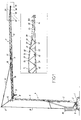
- the tower crane shown in Figure 1, includes a chassis base 1 which supports, by means of an orientation mechanism, a rotating chassis 2 on which is articulated, around a horizontal axis 3, a foldable mast 4 composed of a lower mast element 5 and an element upper mast 6.
- the upper mast element 6 carries, at its top, a crane boom 7 distributor, articulated around a horizontal axis 8 at top of the upper mast element 6.
- the arrow 7, constituting in the state aligned the raceway of a carriage 9, consists of itself, from back to front: from a first main jib element 10, from relatively long; an intermediate element 11 for folding arrow, of relatively short length; of a second main element of arrow 12, of relatively great length; of a first element of arrowhead 13, of relatively short length; and a second arrowhead element 14, of relatively short length, which constitutes the extreme element of the arrow 7. All these arrow elements 10 at 14 are articulated between them two by two, around horizontal axes, and are are aligned in the working position of the crane (Figure 1), to form the track of the carriage 9.
- a rigid arrow punch 15 At the base of the first main arrow element 10, also called arrow foot, is articulated a rigid arrow punch 15, inclined towards the rear of the crane in the working position.
- An arrow rod 16 connects the vertex 17 of the arrow punch 15 at a point 18 of the chord upper part of the jib foot 10.
- a jib retaining rod 19 connects the top 17 of the arrow punch 15 to the revolving frame 2, which carries another ballast 20.
- Motorized means 21 of the jack type are associated with the intermediate boom folding element 11, to allow the folding down of the second main arrow element 12 on the first main element of arrow 10.
- the arrowhead element 13 which is an element intermediate, is articulated at the front end of the second main element 12 along a horizontal axis 22. This articulation is achievable, on each side of the arrow 7, by a clevis-tenon system, the clevis being located for example on the intermediate element 13, while the tenon belongs to the main boom element 12.
- the intermediate element 13 seen from the side a triangular shape defining a vertex 23.
- the second arrowhead element 14 which is the element extreme, is articulated itself at the front end of the element intermediate 13, along another horizontal axis 24.
- This articulation is, also, achievable on each side of the arrow 7 by a clevis-tenon system, the yoke being located for example on the end element 14, while that the post is located on the intermediate element 13.
- the extreme element 14 is essentially straight, but it also has structures 25 defining a horizontal articulation axis 26.
- the unfolding-folding device intended for the two elements of arrowhead 13 and 14, includes two linkage systems 27, arranged symmetrically on each side of the arrow 7, in planes parallel verticals.
- Each linkage system 27 consists of a lever 28, a front link 29 and a rear link 30.
- the lever 28 which is a three-point lever, is articulated by its intermediate point on the vertex 23 of the intermediate element 13 of the arrowhead, around a transverse horizontal axis 31.
- This lever 28 has at its rear end a hole 32, intended for its locking in working position.
- the front link 29 is articulated, by one end, at the point of front articulation 33 of lever 28, along a horizontal axis. To his other end, the front link 29 is articulated with the end element 14 of the arrowhead, along the horizontal axis 26 previously mentioned.
- the rear connecting rod 30 is articulated, by one end, at the point rear articulation 34 of the lever 28, along a horizontal axis. To his other end, the rear link 30 is articulated, along a horizontal axis 35, with the front of the main boom element 12.
- This connecting rod 30 comprises a hole 36 for locking it in the working position.
- the unfolding-folding device also includes an arm for unfolding 37, articulated around a horizontal axis 38 on a crosspiece 39 (see Figure 3) integral with the front of the main boom element 12.
- the unfolding arm 37 comprises, at its free end, a pulley 40 intended at the passage of the lifting cable 41.
- This arm 37 has a cut in "V" shape 42, allowing it to rest on the cross-member 39 in position of use (for unfolding and folding the arrowhead elements 13 and 14).
- the unfolding arm 37 also includes means for locking by pinning in transport position, position in which it is folded back against the main boom element 12.
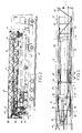
- the unfolding-folding device also includes a sling 43 (see Figure 2), fixed by loops on the front cross member 44 of the end element 14 of the arrowhead, and intended to hang (in folded transport position) on the rear end of the jib foot 10.
- the motorization of the movements of the device is ensured, on the one hand, by the lifting cable 41, the end of which is fixed by a swivel at the front end of the end element 14 of the tip of arrow, and on the other hand, by the jack 21 associated with the intermediate element of folding 11 and ensuring the general unfolding-folding of the boom 7.
- the lifting cable 41 is first given "slack", by the control of its winch.
- the unfolding arm 37 is unlocked, by withdrawn, and it is tilted manually to bring it into position operating reading, supported on the cross-member 39.
- the lifting cable 41 is then placed on the pulley 40 of the unfolding arm 37.
- arrow 7 is unfolded by a small angle, for example of the order of 5 °, as suggested by the arrow F in Figure 2, to raise slightly main element 12 and the region of the arrowhead, and allow the sling 43 to escape from the rear end of the jib foot 10.
- the lifting cable 41 is then tightened, which then pulls on the front end of the end element 14 of the arrowhead, and activates the two linkage systems 27, thus causing the opening simultaneous angle between the front element 14 and the intermediate element 13 of the arrowhead, and of the angle between the intermediate element 13 and the second main element 12 of the arrow.
- the movement thus initiated is continued, until the complete alignment of elements 12, 13 and 14 of the arrow - see the intermediate positions in Figures 5 and 6, and the position end of figure 7.
- the arrow 7 is then folded back, using the jack 21, to bring back the main element 12 in its initial low position, the arrowhead being now aligned with this main element 12.
Landscapes
- Engineering & Computer Science (AREA)
- Structural Engineering (AREA)
- Transportation (AREA)
- Mechanical Engineering (AREA)
- Jib Cranes (AREA)
Applications Claiming Priority (2)
| Application Number | Priority Date | Filing Date | Title |
|---|---|---|---|
| FR9902657A FR2790252B1 (fr) | 1999-02-26 | 1999-02-26 | Dispositif de depliage ou repliage simultane d'elements de pointe de fleche de grue |
| FR9902657 | 1999-02-26 |
Publications (2)
| Publication Number | Publication Date |
|---|---|
| EP1031530A1 true EP1031530A1 (de) | 2000-08-30 |
| EP1031530B1 EP1031530B1 (de) | 2004-01-02 |
Family
ID=9542782
Family Applications (1)
| Application Number | Title | Priority Date | Filing Date |
|---|---|---|---|
| EP00420021A Expired - Lifetime EP1031530B1 (de) | 1999-02-26 | 2000-02-01 | Vorrichtung zum gleichzeitigen Zusammenklappen oder Aufklappen von Teilen der Spitze eines Kranauslegers |
Country Status (7)
| Country | Link |
|---|---|
| US (1) | US6276541B1 (de) |
| EP (1) | EP1031530B1 (de) |
| JP (1) | JP2000255985A (de) |
| DE (1) | DE60007467T2 (de) |
| ES (1) | ES2212976T3 (de) |
| FR (1) | FR2790252B1 (de) |
| RU (1) | RU2256599C2 (de) |
Cited By (4)
| Publication number | Priority date | Publication date | Assignee | Title |
|---|---|---|---|---|
| WO2011160804A1 (de) * | 2010-06-23 | 2011-12-29 | Patrick Kramer | Fahrzeug zum transportieren von ballastgewichten |
| CN103508333A (zh) * | 2012-06-21 | 2014-01-15 | 徐工集团工程机械股份有限公司 | 拉板装置及起重机 |
| CN103626051A (zh) * | 2013-09-05 | 2014-03-12 | 中联重科股份有限公司 | 应用于塔机的拉杆安装装置及拉杆安装方法 |
| CN105384089A (zh) * | 2015-10-30 | 2016-03-09 | 徐州建机工程机械有限公司 | 一种塔机起重臂拉杆结构 |
Families Citing this family (12)
| Publication number | Priority date | Publication date | Assignee | Title |
|---|---|---|---|---|
| ITMI20010116A1 (it) * | 2001-01-23 | 2002-07-23 | San Marco Internat S R L | Gru a torre a struttura composita automontante con torre ripiegabile e sfilabile e braccio a piu' porzioni |
| FR2839962B1 (fr) * | 2002-05-21 | 2004-10-29 | Potain Sa | Grue a tour avec contre-fleche repliable |
| ITMI20021957A1 (it) * | 2002-09-16 | 2004-03-17 | San Marco Internat S R L | Gru a torre automontante con torre ripiegabile e sfilabile e braccio a piu' porzioni ripiegabili |
| US7878346B1 (en) | 2008-08-25 | 2011-02-01 | Link-Belt Construction Equipment Co., L.P., Lllp | Adaptable boom extension for a mobile crane having a telescoping boom |
| DE202017107301U1 (de) * | 2017-09-01 | 2018-12-07 | Liebherr-Werk Biberach Gmbh | Turmdrehkran |
| DE102018115519B3 (de) * | 2018-06-27 | 2019-09-12 | Terex Global Gmbh | Fahrzeugkran mit einem beweglichen Adapter zwischen Hauptausleger und Hauptauslegerverlängerung |
| CN110697436B (zh) * | 2019-10-16 | 2020-12-01 | 长沙理工大学 | 一种水平旋转的折叠臂输送机 |
| FR3102763B1 (fr) * | 2019-10-31 | 2021-11-12 | Manitowoc Crane Group France | Grue à tour avec poinçon à pliage et dépliage automatiques |
| CN111787086B (zh) * | 2020-06-24 | 2022-08-09 | 中国三峡建设管理有限公司 | 一种混凝土施工中缆机停靠装料平台桩号识别的方法 |
| JP7555840B2 (ja) | 2021-02-05 | 2024-09-25 | 清水建設株式会社 | タワークレーンの運搬ユニット及びタワークレーンの運搬方法 |
| FR3123642B1 (fr) * | 2021-06-07 | 2023-04-28 | Manitowoc Crane Group France | Grue à montage automatisé avec contrôle des opérations de changement de configuration |
| CN114737763B (zh) * | 2022-03-15 | 2024-01-19 | 中联重科股份有限公司 | 臂架系统、控制方法及工程机械 |
Citations (3)
| Publication number | Priority date | Publication date | Assignee | Title |
|---|---|---|---|---|
| DE3433117A1 (de) * | 1984-09-08 | 1986-03-20 | Peiner Hebe- Und Transportsysteme Gmbh, 5500 Trier | Turmkran mit dreiteiligem ausleger |
| EP0536060A1 (de) * | 1991-10-02 | 1993-04-07 | Potain | Selbsttätig klappbarer Kranausleger |
| EP0733584A1 (de) * | 1995-03-22 | 1996-09-25 | Potain | Automatische Aufrichtvorrichtung für einen Kran mit zusammenklappbarem Ausleger |
Family Cites Families (4)
| Publication number | Priority date | Publication date | Assignee | Title |
|---|---|---|---|---|
| US2573528A (en) * | 1950-11-10 | 1951-10-30 | Moore Corp Lee C | Folding mast structure |
| ATE68772T1 (de) * | 1988-03-02 | 1991-11-15 | Potain Sa | Zusammenlegbarer kran mit automatischer und schneller aufrichtung. |
| IT1234395B (it) * | 1989-06-16 | 1992-05-18 | Ferreri Andrea | Braccio di gru |
| FR2665429B1 (fr) * | 1990-07-31 | 1992-10-02 | Cadillon Sa | Grue a montage automatise, avec fleche repliable lateralement. |
-
1999
- 1999-02-26 FR FR9902657A patent/FR2790252B1/fr not_active Expired - Fee Related
-
2000
- 2000-02-01 EP EP00420021A patent/EP1031530B1/de not_active Expired - Lifetime
- 2000-02-01 DE DE60007467T patent/DE60007467T2/de not_active Expired - Lifetime
- 2000-02-01 ES ES00420021T patent/ES2212976T3/es not_active Expired - Lifetime
- 2000-02-11 US US09/502,040 patent/US6276541B1/en not_active Expired - Lifetime
- 2000-02-25 JP JP2000049319A patent/JP2000255985A/ja active Pending
- 2000-02-25 RU RU2000104739/11A patent/RU2256599C2/ru not_active IP Right Cessation
Patent Citations (3)
| Publication number | Priority date | Publication date | Assignee | Title |
|---|---|---|---|---|
| DE3433117A1 (de) * | 1984-09-08 | 1986-03-20 | Peiner Hebe- Und Transportsysteme Gmbh, 5500 Trier | Turmkran mit dreiteiligem ausleger |
| EP0536060A1 (de) * | 1991-10-02 | 1993-04-07 | Potain | Selbsttätig klappbarer Kranausleger |
| EP0733584A1 (de) * | 1995-03-22 | 1996-09-25 | Potain | Automatische Aufrichtvorrichtung für einen Kran mit zusammenklappbarem Ausleger |
Cited By (8)
| Publication number | Priority date | Publication date | Assignee | Title |
|---|---|---|---|---|
| WO2011160804A1 (de) * | 2010-06-23 | 2011-12-29 | Patrick Kramer | Fahrzeug zum transportieren von ballastgewichten |
| US9061625B2 (en) | 2010-06-23 | 2015-06-23 | Patrick Kramer | Vehicle for transporting ballast weights |
| EA024308B1 (ru) * | 2010-06-23 | 2016-09-30 | Патрик Крамер | Автомобильный кран |
| CN103508333A (zh) * | 2012-06-21 | 2014-01-15 | 徐工集团工程机械股份有限公司 | 拉板装置及起重机 |
| CN103508333B (zh) * | 2012-06-21 | 2015-11-25 | 徐工集团工程机械股份有限公司 | 拉板装置及起重机 |
| CN103626051A (zh) * | 2013-09-05 | 2014-03-12 | 中联重科股份有限公司 | 应用于塔机的拉杆安装装置及拉杆安装方法 |
| CN103626051B (zh) * | 2013-09-05 | 2015-08-05 | 中联重科股份有限公司 | 应用于塔机的拉杆安装装置及拉杆安装方法 |
| CN105384089A (zh) * | 2015-10-30 | 2016-03-09 | 徐州建机工程机械有限公司 | 一种塔机起重臂拉杆结构 |
Also Published As
| Publication number | Publication date |
|---|---|
| FR2790252B1 (fr) | 2001-04-06 |
| ES2212976T3 (es) | 2004-08-16 |
| FR2790252A1 (fr) | 2000-09-01 |
| DE60007467D1 (de) | 2004-02-05 |
| RU2256599C2 (ru) | 2005-07-20 |
| US6276541B1 (en) | 2001-08-21 |
| DE60007467T2 (de) | 2004-12-02 |
| EP1031530B1 (de) | 2004-01-02 |
| JP2000255985A (ja) | 2000-09-19 |
Similar Documents
| Publication | Publication Date | Title |
|---|---|---|
| EP1031530B1 (de) | Vorrichtung zum gleichzeitigen Zusammenklappen oder Aufklappen von Teilen der Spitze eines Kranauslegers | |
| EP0733584B1 (de) | Automatische Aufrichtvorrichtung für einen Kran mit zusammenklappbarem Ausleger | |
| EP0635450B1 (de) | Verfahren und Vorrichtung zum Montieren der Ausleger von Turmkränen | |
| FR2788758A1 (fr) | Procede et dispositif pour le montage de la tete de mat des grues a tour | |
| FR2712578A1 (fr) | Dispositif pour la manutention d'un conteneur. | |
| EP0362096B1 (de) | Fahrzeugtransporter mit einer teleskopierbaren Ladefläche | |
| FR2487318A1 (fr) | Procede d'extension d'un bras de grue telescopique | |
| EP1172323A1 (de) | Kran mit aus Gliedern bestehendem Kranarm | |
| FR2756551A1 (fr) | Procede et dispositif pour le montage des tirants des fleches de grues a tour | |
| EP1607363A2 (de) | Kran mit einem teleskopierbarem Ausleger | |
| EP1357078B1 (de) | Schwenkbare Kabineeinheit für Turmkran | |
| EP0870726B1 (de) | Selbstaufrichtender Kran mit seitlich zusammenklappbarem Ausleger in der Transportstellung | |
| FR2686843A1 (fr) | Ensemble basculant-coulissant de chargement par traction a partir du sol et de transport, pour porteur routier. | |
| FR2643625A2 (fr) | Grue repliable a fleche en trois elements articules les uns aux autres | |
| EP1352870B1 (de) | Vorrichtung zum Anheben und Aufklappen von dem Mast und zum Anheben von dem Ausleger eines Kranes | |
| EP0873964B1 (de) | Technik zum Aufrichten des Mastes für einen Teleskopkran | |
| FR2548646A1 (fr) | Grue repliable a deploiement rapide | |
| EP3141517B1 (de) | Schnellmontage-kran ohne ballastierung | |
| EP1057776B1 (de) | Kran mit aus Gliedern bestehendem Kranarm | |
| FR2956424A1 (fr) | Plateforme de travail en encorbellement | |
| EP3889094B1 (de) | Kran mit automatisierter montage, der ein abnehmbares ballastelement für den transport auf einem sattel umfasst | |
| FR2810356A1 (fr) | Scene pliable mobile ou structure similaire, destinee notamment aux spectacles itinerants | |
| BE1007563A6 (fr) | Dispositif pour poser des elements de voirie. | |
| FR2541559A1 (fr) | Semoir a chassis repliable lateralement | |
| FR2465867A1 (fr) | Dispositif destine a orienter et a maintenir en differentes positions une plate-forme de travail d'echelle ou de bras elevateur telescopique |
Legal Events
| Date | Code | Title | Description |
|---|---|---|---|
| PUAI | Public reference made under article 153(3) epc to a published international application that has entered the european phase |
Free format text: ORIGINAL CODE: 0009012 |
|
| AK | Designated contracting states |
Kind code of ref document: A1 Designated state(s): BE DE ES IT |
|
| AX | Request for extension of the european patent |
Free format text: AL;LT;LV;MK;RO;SI |
|
| 17P | Request for examination filed |
Effective date: 20010212 |
|
| AKX | Designation fees paid |
Free format text: BE DE ES IT |
|
| GRAP | Despatch of communication of intention to grant a patent |
Free format text: ORIGINAL CODE: EPIDOSNIGR1 |
|
| GRAS | Grant fee paid |
Free format text: ORIGINAL CODE: EPIDOSNIGR3 |
|
| GRAA | (expected) grant |
Free format text: ORIGINAL CODE: 0009210 |
|
| AK | Designated contracting states |
Kind code of ref document: B1 Designated state(s): BE DE ES IT |
|
| REF | Corresponds to: |
Ref document number: 60007467 Country of ref document: DE Date of ref document: 20040205 Kind code of ref document: P |
|
| REG | Reference to a national code |
Ref country code: ES Ref legal event code: FG2A Ref document number: 2212976 Country of ref document: ES Kind code of ref document: T3 |
|
| PLBE | No opposition filed within time limit |
Free format text: ORIGINAL CODE: 0009261 |
|
| STAA | Information on the status of an ep patent application or granted ep patent |
Free format text: STATUS: NO OPPOSITION FILED WITHIN TIME LIMIT |
|
| 26N | No opposition filed |
Effective date: 20041005 |
|
| PGFP | Annual fee paid to national office [announced via postgrant information from national office to epo] |
Ref country code: BE Payment date: 20050309 Year of fee payment: 6 |
|
| PG25 | Lapsed in a contracting state [announced via postgrant information from national office to epo] |
Ref country code: BE Free format text: LAPSE BECAUSE OF NON-PAYMENT OF DUE FEES Effective date: 20060228 |
|
| BERE | Be: lapsed |
Owner name: *POTAIN Effective date: 20060228 |
|
| PGFP | Annual fee paid to national office [announced via postgrant information from national office to epo] |
Ref country code: DE Payment date: 20140115 Year of fee payment: 15 |
|
| PGFP | Annual fee paid to national office [announced via postgrant information from national office to epo] |
Ref country code: IT Payment date: 20140217 Year of fee payment: 15 Ref country code: ES Payment date: 20140221 Year of fee payment: 15 |
|
| REG | Reference to a national code |
Ref country code: DE Ref legal event code: R119 Ref document number: 60007467 Country of ref document: DE |
|
| PG25 | Lapsed in a contracting state [announced via postgrant information from national office to epo] |
Ref country code: IT Free format text: LAPSE BECAUSE OF NON-PAYMENT OF DUE FEES Effective date: 20150201 |
|
| PG25 | Lapsed in a contracting state [announced via postgrant information from national office to epo] |
Ref country code: DE Free format text: LAPSE BECAUSE OF NON-PAYMENT OF DUE FEES Effective date: 20150901 |
|
| REG | Reference to a national code |
Ref country code: ES Ref legal event code: FD2A Effective date: 20160329 |
|
| PG25 | Lapsed in a contracting state [announced via postgrant information from national office to epo] |
Ref country code: ES Free format text: LAPSE BECAUSE OF NON-PAYMENT OF DUE FEES Effective date: 20150202 |