EP1028295A2 - Einbaugebläse - Google Patents
Einbaugebläse Download PDFInfo
- Publication number
- EP1028295A2 EP1028295A2 EP00890035A EP00890035A EP1028295A2 EP 1028295 A2 EP1028295 A2 EP 1028295A2 EP 00890035 A EP00890035 A EP 00890035A EP 00890035 A EP00890035 A EP 00890035A EP 1028295 A2 EP1028295 A2 EP 1028295A2
- Authority
- EP
- European Patent Office
- Prior art keywords
- cover
- filter
- housing
- blower
- filter cover
- Prior art date
- Legal status (The legal status is an assumption and is not a legal conclusion. Google has not performed a legal analysis and makes no representation as to the accuracy of the status listed.)
- Granted
Links
Images

Classifications
-
- F—MECHANICAL ENGINEERING; LIGHTING; HEATING; WEAPONS; BLASTING
- F24—HEATING; RANGES; VENTILATING
- F24F—AIR-CONDITIONING; AIR-HUMIDIFICATION; VENTILATION; USE OF AIR CURRENTS FOR SCREENING
- F24F7/00—Ventilation
- F24F7/007—Ventilation with forced flow
-
- F—MECHANICAL ENGINEERING; LIGHTING; HEATING; WEAPONS; BLASTING
- F24—HEATING; RANGES; VENTILATING
- F24F—AIR-CONDITIONING; AIR-HUMIDIFICATION; VENTILATION; USE OF AIR CURRENTS FOR SCREENING
- F24F1/00—Room units for air-conditioning, e.g. separate or self-contained units or units receiving primary air from a central station
- F24F1/0007—Indoor units, e.g. fan coil units
- F24F1/00075—Indoor units, e.g. fan coil units receiving air from a central station
-
- F—MECHANICAL ENGINEERING; LIGHTING; HEATING; WEAPONS; BLASTING
- F24—HEATING; RANGES; VENTILATING
- F24F—AIR-CONDITIONING; AIR-HUMIDIFICATION; VENTILATION; USE OF AIR CURRENTS FOR SCREENING
- F24F1/00—Room units for air-conditioning, e.g. separate or self-contained units or units receiving primary air from a central station
- F24F1/0007—Indoor units, e.g. fan coil units
- F24F1/0071—Indoor units, e.g. fan coil units with means for purifying supplied air
-
- F—MECHANICAL ENGINEERING; LIGHTING; HEATING; WEAPONS; BLASTING
- F24—HEATING; RANGES; VENTILATING
- F24F—AIR-CONDITIONING; AIR-HUMIDIFICATION; VENTILATION; USE OF AIR CURRENTS FOR SCREENING
- F24F2221/00—Details or features not otherwise provided for
- F24F2221/14—Details or features not otherwise provided for mounted on the ceiling
Definitions
- the invention relates to a built-in fan with a front open housing for receiving the fan and a filter cover and a cover frame, a filter can be placed on the filter cover and in the Cover frame a cover plate can be inserted.
- Such built-in fans are used for flush-mounting installation and Ventilation devices, the devices required for blower operation, like blower, filter cover and filter, in one offset on the wall Housing housed and then to the outside by means of a cover frame and be covered with a cover plate.
- the known built-in fans to use all these devices individually in the housing and to attach, which means a rather tedious and time-consuming assembly.
- the invention is therefore based on the object of a built-in fan to create the type described above, which is fully functional characterized by its rational installation options.
- the invention solves this problem in that fans, filter covers and Cover frame form a prefabricated installation unit in which the fan and the filter cover firmly and the filter cover and the cover frame against spring force are detachably connected to each other, which installation unit abutments of the housing assigned spring catches for locking insertion into the Has housing.
- This installation unit therefore needs to be walled in Housing only to be pushed in until the spring catches the abutment reach behind the housing and fix the installation unit in the housing, and the blower is essentially assembled.
- the one opposite the filter cover Liftable, sprung cover frame bridges the installation distance between Front of the housing and wall surface and lies down exactly and cleanly Cover the housing on the wall.
- the spring catches are releasably attached to the filter cover from the outside, you can the locking of the installation unit, for example to remove a defective one Blower or the like, simply released by loosening the spring catches and the installation unit can be removed in just a few steps for maintenance purposes.
- the cover frame and thus the Turn the cover plate in relation to the housing or the installation unit can, attack the tension springs on the cover frame so that there are no resilient holding forces for the cover frame and cover frame twisted into its correct position also its adjusted position maintains.
- the tension springs on the cover frame this forms, for example, diagonal anchor webs in the corners which the tension springs are suspended, which with sufficient freedom of rotation brings itself.
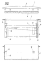
- a built-in blower 1 comprises a housing 2 which is open on the front and which Blower 3 and a filter cover 4 and a cover frame 5, a filter 6 placed on the filter cover 4 and then in the cover frame 5 a cover plate 7 is inserted.
- the housing 2 is in the area of an exhaust duct L built into a masonry M and then the blower assembled together with the accessories.
- form Blower 3, filter cover 4 and cover frame 5 a prefabricated installation unit 8, the side spring catches 9 for locking with on the housing side walls provided abutments 10.
- filter covers 4 and Blower 3 of the installation unit 8 firmly connected to each other, the cover frame 5, on the other hand, can be lifted against the spring force on the filter cover 4 via tension springs 11 articulated, the tension springs 11 along projecting into the housing interior Corner lugs 12 of the filter cover 4 run and at the ends of these lugs attack.
- the cover frame 5 lies under pretension of the tension springs 11 corresponding to the walling depth of the housing 2 in the masonry M on the outside of the wall surface and ensures a clean edge finish.
Landscapes
- Engineering & Computer Science (AREA)
- Chemical & Material Sciences (AREA)
- Combustion & Propulsion (AREA)
- Mechanical Engineering (AREA)
- General Engineering & Computer Science (AREA)
- Structures Of Non-Positive Displacement Pumps (AREA)
- Filtering Of Dispersed Particles In Gases (AREA)
- Air-Conditioning For Vehicles (AREA)
- Power Steering Mechanism (AREA)
- Walking Sticks, Umbrellas, And Fans (AREA)
- Thermistors And Varistors (AREA)
- Diaphragms For Electromechanical Transducers (AREA)
- Cooling Or The Like Of Electrical Apparatus (AREA)
Abstract
Description
- Fig. 1
- ein erfindungsgemäßes Einbaugebläse mit seinen Bestandteilen in einer teilgeschnittenen Explosionsdarstellung und
- Fig. 2
- ein ordnungsgemäß eingebautes Einbaugebläse im Querschnitt.
Claims (5)
- Einbaugebläse mit einem vorderseitig offenen Gehäuse (2) zur Aufnahme des Gebläses (3) sowie eines Filterdeckels (4) und eines Abdeckrahmens (5), wobei auf den Filterdeckel (4) ein Filter (6) auflegbar und in den Abdeckrahmen (5) eine Abdeckplatte (7) einsteckbar ist, dadurch gekennzeichnet, daß Gebläse (3), Filterdeckel (4) und Abdeckrahmen (5) eine vorgefertigte Einbaueinheit (8) bilden, in der das Gebläse (3) und der Filterdeckel (4) fest und der Filterdeckel (4) und der Abdeckrahmen (5) gegen Federkraft abhebbar miteinander verbunden sind, welche Einbaueinheit (8) Widerlagern (10) des Gehäuses (2) zugeordnete Federrasten (9) zum verrastenden Einsetzen in das Gehäuse aufweist.
- Einbaugebläse nach Anspruch 1, dadurch gekennzeichnet, daß die Federrasten (9) von außen lösbar am Filterdeckel (4) befestigt sind.
- Einbaugebläse nach Anspruch 1 oder 2, dadurch gekennzeichnet, daß der Filterdeckel (4) mit ins Gehäuseinnere vorragenden Eckansätzen (12) versehen ist, an denen sich Zugfedern (11) zur Anlenkung des Abdeckrahmens (5) abstützen.
- Einbaugebläse nach Anspruch 3, dadurch gekennzeichnet, daß die Zugfedern (11) querverschiebbar am Abdeckrahmen (5) angreifen.
- Einbaugebläse nach einem der Ansprüche 1 bis 4, dadurch gekennzeichnet, daß im Filterdeckel ein mit einer eigenen Abdeckung versehenes Installationsfach für elektrische Schalt- und Anschlußeinrichtungen ausgeformt ist.
Priority Applications (1)
| Application Number | Priority Date | Filing Date | Title |
|---|---|---|---|
| AT00890035T ATE323264T1 (de) | 1999-02-12 | 2000-02-10 | Einbaugebläse |
Applications Claiming Priority (2)
| Application Number | Priority Date | Filing Date | Title |
|---|---|---|---|
| AT19999 | 1999-02-12 | ||
| AT0019999A AT410125B (de) | 1999-02-12 | 1999-02-12 | Einbaugebläse |
Publications (3)
| Publication Number | Publication Date |
|---|---|
| EP1028295A2 true EP1028295A2 (de) | 2000-08-16 |
| EP1028295A3 EP1028295A3 (de) | 2005-04-13 |
| EP1028295B1 EP1028295B1 (de) | 2006-04-12 |
Family
ID=3484122
Family Applications (1)
| Application Number | Title | Priority Date | Filing Date |
|---|---|---|---|
| EP00890035A Expired - Lifetime EP1028295B1 (de) | 1999-02-12 | 2000-02-10 | Einbaugebläse |
Country Status (6)
| Country | Link |
|---|---|
| EP (1) | EP1028295B1 (de) |
| AT (2) | AT410125B (de) |
| DE (1) | DE50012547D1 (de) |
| DK (1) | DK1028295T3 (de) |
| ES (1) | ES2259991T3 (de) |
| PT (1) | PT1028295E (de) |
Cited By (2)
| Publication number | Priority date | Publication date | Assignee | Title |
|---|---|---|---|---|
| CN104696292A (zh) * | 2013-12-10 | 2015-06-10 | 台达电子工业股份有限公司 | 换气扇 |
| AT517980A1 (de) * | 2015-11-27 | 2017-06-15 | Limot Elektromotorenbaugesellschaft M B H & Co Kg | Vorrichtung zum Lüften von Räumen |
Citations (4)
| Publication number | Priority date | Publication date | Assignee | Title |
|---|---|---|---|---|
| FR2604492A1 (fr) * | 1986-09-30 | 1988-04-01 | Sueddeutsche Kuehler Behr | Dispositif de fixation d'un ventilateur dans un boitier |
| US4834615A (en) * | 1987-06-04 | 1989-05-30 | Siemens Aktiengesellschaft | Mounting arrangement for an axial fan |
| EP0439667A1 (de) * | 1990-02-02 | 1991-08-07 | Otto Pfannenberg Elektro-Spezialgerätebau Gmbh | Filterlüfter für den Einbau in der Wand eines Schaltschrankes od. dgl. |
| DE4312664C1 (de) * | 1993-04-20 | 1994-07-28 | Loh Kg Rittal Werk | Filterlüfter |
Family Cites Families (9)
| Publication number | Priority date | Publication date | Assignee | Title |
|---|---|---|---|---|
| US2800849A (en) * | 1955-04-20 | 1957-07-30 | Nutone Inc | Ventilator unit |
| JPH01167547A (ja) * | 1987-12-21 | 1989-07-03 | Matsushita Seiko Co Ltd | 換気扇 |
| JPH0282044A (ja) * | 1988-09-19 | 1990-03-22 | Sanyo Electric Co Ltd | 換気扇 |
| JP2788364B2 (ja) * | 1991-03-15 | 1998-08-20 | 株式会社東芝 | フィルタ付換気扇 |
| JP2616518B2 (ja) * | 1991-08-01 | 1997-06-04 | 三菱電機株式会社 | 換気装置 |
| DE9306032U1 (de) * | 1993-04-21 | 1993-12-02 | Loh Kg Rittal Werk | Filterlüfter |
| JPH0742993A (ja) * | 1993-05-21 | 1995-02-10 | Toshiba Corp | 天井用換気扇 |
| JP3091354B2 (ja) * | 1993-11-29 | 2000-09-25 | 東芝キヤリア株式会社 | 換気扇 |
| JPH07217957A (ja) * | 1994-01-27 | 1995-08-18 | Toshiba Corp | 換気扇 |
-
1999
- 1999-02-12 AT AT0019999A patent/AT410125B/de not_active IP Right Cessation
-
2000
- 2000-02-10 EP EP00890035A patent/EP1028295B1/de not_active Expired - Lifetime
- 2000-02-10 ES ES00890035T patent/ES2259991T3/es not_active Expired - Lifetime
- 2000-02-10 DE DE50012547T patent/DE50012547D1/de not_active Expired - Lifetime
- 2000-02-10 PT PT00890035T patent/PT1028295E/pt unknown
- 2000-02-10 DK DK00890035T patent/DK1028295T3/da active
- 2000-02-10 AT AT00890035T patent/ATE323264T1/de active
Patent Citations (4)
| Publication number | Priority date | Publication date | Assignee | Title |
|---|---|---|---|---|
| FR2604492A1 (fr) * | 1986-09-30 | 1988-04-01 | Sueddeutsche Kuehler Behr | Dispositif de fixation d'un ventilateur dans un boitier |
| US4834615A (en) * | 1987-06-04 | 1989-05-30 | Siemens Aktiengesellschaft | Mounting arrangement for an axial fan |
| EP0439667A1 (de) * | 1990-02-02 | 1991-08-07 | Otto Pfannenberg Elektro-Spezialgerätebau Gmbh | Filterlüfter für den Einbau in der Wand eines Schaltschrankes od. dgl. |
| DE4312664C1 (de) * | 1993-04-20 | 1994-07-28 | Loh Kg Rittal Werk | Filterlüfter |
Cited By (4)
| Publication number | Priority date | Publication date | Assignee | Title |
|---|---|---|---|---|
| CN104696292A (zh) * | 2013-12-10 | 2015-06-10 | 台达电子工业股份有限公司 | 换气扇 |
| CN104696292B (zh) * | 2013-12-10 | 2018-05-29 | 台达电子工业股份有限公司 | 换气扇 |
| AT517980A1 (de) * | 2015-11-27 | 2017-06-15 | Limot Elektromotorenbaugesellschaft M B H & Co Kg | Vorrichtung zum Lüften von Räumen |
| AT517980B1 (de) * | 2015-11-27 | 2019-07-15 | Limot Elektromotorenbaugesellschaft M B H & Co Kg | Vorrichtung zum Lüften von Räumen |
Also Published As
| Publication number | Publication date |
|---|---|
| DK1028295T3 (da) | 2006-08-21 |
| DE50012547D1 (de) | 2006-05-24 |
| ATA19999A (de) | 2002-06-15 |
| ATE323264T1 (de) | 2006-04-15 |
| EP1028295A3 (de) | 2005-04-13 |
| EP1028295B1 (de) | 2006-04-12 |
| PT1028295E (pt) | 2006-07-31 |
| ES2259991T3 (es) | 2006-11-01 |
| AT410125B (de) | 2003-02-25 |
Similar Documents
| Publication | Publication Date | Title |
|---|---|---|
| EP1859518B1 (de) | Geräteadapter | |
| EP1467056A2 (de) | Garagentorantrieb mit Leuchteinheit | |
| EP1681427A1 (de) | Kombinierbare Steckzarge | |
| DE3412291A1 (de) | Sockel fuer einen schaltschrank | |
| EP1028295A2 (de) | Einbaugebläse | |
| EP0993171A2 (de) | Aufnahmegehäuse einer Türstation einer Türsprechanlage | |
| DE4011735C2 (de) | ||
| CH695715A5 (de) | Apparat für elektrische Hausinstallationen. | |
| DE4013457C2 (de) | Anschluß- und Aufhängevorrichtung für Deckenleuchten | |
| DE102017220452A1 (de) | Modulare Antriebsvorrichtung | |
| EP0355524B1 (de) | Leitungskanal | |
| DE202016004646U1 (de) | Elektrisches Installationsgerät | |
| EP3057187B1 (de) | Gerät der gebäudeinstallationstechnik mit einem anzeige- und/oder bedienelement | |
| EP0534259B1 (de) | Elektronisches Steuergerät | |
| EP0486977A1 (de) | Anzeige- und Bedien-Tableau | |
| EP3670815B1 (de) | Betätigungssystem zum motorischen betätigen einer verschlussvorrichtung für eine öffnung einer wand oder zum betätigen einer verdunklungsvorrichtung | |
| DE2658745B1 (de) | Reinigungsanlage fuer die Heckscheibe eines Kraftfahrzeuges | |
| DE19630616C2 (de) | Lüfter für die Gebäudeentlüftung | |
| DE2208445A1 (de) | Netzstrombetriebene elektrische schaltuhr zum uhrzeitabhaengigen schalten der stromzufuhr netzstrombetriebener elektrischer geraete | |
| EP0980200A2 (de) | Moduleinheit für eine Türanlage, insbesondere Türsprechanlage | |
| DE4128355C1 (en) | Electronic equipment housing e.g. TV, radio cabinet, allowing access for servicing - has frame for walls using plug flaps fitting grooves and held in place by spring-loaded fasteners releasable by operating elements | |
| CH678224A5 (en) | Fume hood for kitchen - has fan driven by mains-powered motor controlled by LV switch panel | |
| DE8517303U1 (de) | Installationseinrichtung | |
| DE2619434C3 (de) | Innenleuchte für Leuchtstofflampen | |
| DE10210481C1 (de) | Schaltschrank mit Rahmengestell und Verkleidungselementen |
Legal Events
| Date | Code | Title | Description |
|---|---|---|---|
| PUAI | Public reference made under article 153(3) epc to a published international application that has entered the european phase |
Free format text: ORIGINAL CODE: 0009012 |
|
| AK | Designated contracting states |
Kind code of ref document: A2 Designated state(s): AT BE CH CY DE DK ES FI FR GB GR IE IT LI LU MC NL PT SE |
|
| AX | Request for extension of the european patent |
Free format text: AL;LT;LV;MK;RO;SI |
|
| PUAL | Search report despatched |
Free format text: ORIGINAL CODE: 0009013 |
|
| AK | Designated contracting states |
Kind code of ref document: A3 Designated state(s): AT BE CH CY DE DK ES FI FR GB GR IE IT LI LU MC NL PT SE |
|
| AX | Request for extension of the european patent |
Extension state: AL LT LV MK RO SI |
|
| RIC1 | Information provided on ipc code assigned before grant |
Ipc: 7F 24F 7/007 B Ipc: 7F 04D 29/60 B Ipc: 7F 04D 29/70 B Ipc: 7F 24F 7/013 A |
|
| 17P | Request for examination filed |
Effective date: 20050506 |
|
| GRAP | Despatch of communication of intention to grant a patent |
Free format text: ORIGINAL CODE: EPIDOSNIGR1 |
|
| AKX | Designation fees paid |
Designated state(s): AT BE CH CY DE DK ES FI FR GB GR IE IT LI LU MC NL PT SE |
|
| GRAS | Grant fee paid |
Free format text: ORIGINAL CODE: EPIDOSNIGR3 |
|
| GRAA | (expected) grant |
Free format text: ORIGINAL CODE: 0009210 |
|
| AK | Designated contracting states |
Kind code of ref document: B1 Designated state(s): AT BE CH CY DE DK ES FI FR GB GR IE IT LI LU MC NL PT SE |
|
| PG25 | Lapsed in a contracting state [announced via postgrant information from national office to epo] |
Ref country code: IT Free format text: LAPSE BECAUSE OF FAILURE TO SUBMIT A TRANSLATION OF THE DESCRIPTION OR TO PAY THE FEE WITHIN THE PRESCRIBED TIME-LIMIT;WARNING: LAPSES OF ITALIAN PATENTS WITH EFFECTIVE DATE BEFORE 2007 MAY HAVE OCCURRED AT ANY TIME BEFORE 2007. THE CORRECT EFFECTIVE DATE MAY BE DIFFERENT FROM THE ONE RECORDED. Effective date: 20060412 |
|
| REG | Reference to a national code |
Ref country code: GB Ref legal event code: FG4D Free format text: NOT ENGLISH |
|
| REG | Reference to a national code |
Ref country code: CH Ref legal event code: EP |
|
| REF | Corresponds to: |
Ref document number: 50012547 Country of ref document: DE Date of ref document: 20060524 Kind code of ref document: P |
|
| REG | Reference to a national code |
Ref country code: CH Ref legal event code: NV Representative=s name: CABINET ROLAND NITHARDT CONSEILS EN PROPRIETE INDU Ref country code: IE Ref legal event code: FG4D Free format text: LANGUAGE OF EP DOCUMENT: GERMAN |
|
| GBT | Gb: translation of ep patent filed (gb section 77(6)(a)/1977) |
Effective date: 20060531 |
|
| REG | Reference to a national code |
Ref country code: SE Ref legal event code: TRGR |
|
| REG | Reference to a national code |
Ref country code: PT Ref legal event code: SC4A Effective date: 20060525 |
|
| REG | Reference to a national code |
Ref country code: GR Ref legal event code: EP Ref document number: 20060402070 Country of ref document: GR |
|
| REG | Reference to a national code |
Ref country code: DK Ref legal event code: T3 |
|
| REG | Reference to a national code |
Ref country code: ES Ref legal event code: FG2A Ref document number: 2259991 Country of ref document: ES Kind code of ref document: T3 |
|
| ET | Fr: translation filed | ||
| PGFP | Annual fee paid to national office [announced via postgrant information from national office to epo] |
Ref country code: IE Payment date: 20070207 Year of fee payment: 8 |
|
| PGFP | Annual fee paid to national office [announced via postgrant information from national office to epo] |
Ref country code: CY Payment date: 20070208 Year of fee payment: 8 Ref country code: SE Payment date: 20070208 Year of fee payment: 8 |
|
| PGFP | Annual fee paid to national office [announced via postgrant information from national office to epo] |
Ref country code: LU Payment date: 20070214 Year of fee payment: 8 |
|
| PGFP | Annual fee paid to national office [announced via postgrant information from national office to epo] |
Ref country code: DK Payment date: 20070215 Year of fee payment: 8 Ref country code: FI Payment date: 20070215 Year of fee payment: 8 |
|
| PLBE | No opposition filed within time limit |
Free format text: ORIGINAL CODE: 0009261 |
|
| STAA | Information on the status of an ep patent application or granted ep patent |
Free format text: STATUS: NO OPPOSITION FILED WITHIN TIME LIMIT |
|
| PGFP | Annual fee paid to national office [announced via postgrant information from national office to epo] |
Ref country code: MC Payment date: 20070219 Year of fee payment: 8 |
|
| PGFP | Annual fee paid to national office [announced via postgrant information from national office to epo] |
Ref country code: NL Payment date: 20070227 Year of fee payment: 8 |
|
| 26N | No opposition filed |
Effective date: 20070115 |
|
| REG | Reference to a national code |
Ref country code: DK Ref legal event code: EBP |
|
| EUG | Se: european patent has lapsed | ||
| PG25 | Lapsed in a contracting state [announced via postgrant information from national office to epo] |
Ref country code: FI Free format text: LAPSE BECAUSE OF NON-PAYMENT OF DUE FEES Effective date: 20080210 Ref country code: MC Free format text: LAPSE BECAUSE OF NON-PAYMENT OF DUE FEES Effective date: 20080228 |
|
| NLV4 | Nl: lapsed or anulled due to non-payment of the annual fee |
Effective date: 20080901 |
|
| PG25 | Lapsed in a contracting state [announced via postgrant information from national office to epo] |
Ref country code: NL Free format text: LAPSE BECAUSE OF NON-PAYMENT OF DUE FEES Effective date: 20080901 |
|
| PG25 | Lapsed in a contracting state [announced via postgrant information from national office to epo] |
Ref country code: IE Free format text: LAPSE BECAUSE OF NON-PAYMENT OF DUE FEES Effective date: 20080211 Ref country code: SE Free format text: LAPSE BECAUSE OF NON-PAYMENT OF DUE FEES Effective date: 20080211 Ref country code: DK Free format text: LAPSE BECAUSE OF NON-PAYMENT OF DUE FEES Effective date: 20080229 |
|
| PG25 | Lapsed in a contracting state [announced via postgrant information from national office to epo] |
Ref country code: CY Free format text: LAPSE BECAUSE OF NON-PAYMENT OF DUE FEES Effective date: 20080210 |
|
| PG25 | Lapsed in a contracting state [announced via postgrant information from national office to epo] |
Ref country code: LU Free format text: LAPSE BECAUSE OF NON-PAYMENT OF DUE FEES Effective date: 20080210 |
|
| PGFP | Annual fee paid to national office [announced via postgrant information from national office to epo] |
Ref country code: GR Payment date: 20110225 Year of fee payment: 12 |
|
| PGFP | Annual fee paid to national office [announced via postgrant information from national office to epo] |
Ref country code: PT Payment date: 20111128 Year of fee payment: 13 |
|
| PGFP | Annual fee paid to national office [announced via postgrant information from national office to epo] |
Ref country code: BE Payment date: 20111202 Year of fee payment: 13 |
|
| PGFP | Annual fee paid to national office [announced via postgrant information from national office to epo] |
Ref country code: FR Payment date: 20120223 Year of fee payment: 13 |
|
| PGFP | Annual fee paid to national office [announced via postgrant information from national office to epo] |
Ref country code: GB Payment date: 20120222 Year of fee payment: 13 |
|
| REG | Reference to a national code |
Ref country code: PT Ref legal event code: MM4A Free format text: LAPSE DUE TO NON-PAYMENT OF FEES Effective date: 20130812 |
|
| BERE | Be: lapsed |
Owner name: *LIMOT ELEKTROMOTORENBAUG.- M.B.H. & CO. K.G. Effective date: 20130228 |
|
| REG | Reference to a national code |
Ref country code: GR Ref legal event code: ML Ref document number: 20060402070 Country of ref document: GR Effective date: 20130904 |
|
| GBPC | Gb: european patent ceased through non-payment of renewal fee |
Effective date: 20130210 |
|
| PG25 | Lapsed in a contracting state [announced via postgrant information from national office to epo] |
Ref country code: GR Free format text: LAPSE BECAUSE OF NON-PAYMENT OF DUE FEES Effective date: 20130904 Ref country code: PT Free format text: LAPSE BECAUSE OF NON-PAYMENT OF DUE FEES Effective date: 20130812 |
|
| REG | Reference to a national code |
Ref country code: FR Ref legal event code: ST Effective date: 20131031 |
|
| PG25 | Lapsed in a contracting state [announced via postgrant information from national office to epo] |
Ref country code: BE Free format text: LAPSE BECAUSE OF NON-PAYMENT OF DUE FEES Effective date: 20130228 Ref country code: FR Free format text: LAPSE BECAUSE OF NON-PAYMENT OF DUE FEES Effective date: 20130228 Ref country code: GB Free format text: LAPSE BECAUSE OF NON-PAYMENT OF DUE FEES Effective date: 20130210 |
|
| PGFP | Annual fee paid to national office [announced via postgrant information from national office to epo] |
Ref country code: ES Payment date: 20180322 Year of fee payment: 19 |
|
| PGFP | Annual fee paid to national office [announced via postgrant information from national office to epo] |
Ref country code: IT Payment date: 20190221 Year of fee payment: 20 Ref country code: CH Payment date: 20190225 Year of fee payment: 20 |
|
| PGFP | Annual fee paid to national office [announced via postgrant information from national office to epo] |
Ref country code: AT Payment date: 20190228 Year of fee payment: 20 |
|
| PGFP | Annual fee paid to national office [announced via postgrant information from national office to epo] |
Ref country code: DE Payment date: 20190426 Year of fee payment: 20 |
|
| REG | Reference to a national code |
Ref country code: DE Ref legal event code: R071 Ref document number: 50012547 Country of ref document: DE |
|
| REG | Reference to a national code |
Ref country code: CH Ref legal event code: PL |
|
| REG | Reference to a national code |
Ref country code: AT Ref legal event code: MK07 Ref document number: 323264 Country of ref document: AT Kind code of ref document: T Effective date: 20200210 |
|
| REG | Reference to a national code |
Ref country code: ES Ref legal event code: FD2A Effective date: 20200327 |
|
| PG25 | Lapsed in a contracting state [announced via postgrant information from national office to epo] |
Ref country code: ES Free format text: LAPSE BECAUSE OF NON-PAYMENT OF DUE FEES Effective date: 20190211 |