EP1027625B1 - Anzeigegerät mit einem gitter-lichtventilarray und interferometrisches optisches system - Google Patents
Anzeigegerät mit einem gitter-lichtventilarray und interferometrisches optisches system Download PDFInfo
- Publication number
- EP1027625B1 EP1027625B1 EP98953870A EP98953870A EP1027625B1 EP 1027625 B1 EP1027625 B1 EP 1027625B1 EP 98953870 A EP98953870 A EP 98953870A EP 98953870 A EP98953870 A EP 98953870A EP 1027625 B1 EP1027625 B1 EP 1027625B1
- Authority
- EP
- European Patent Office
- Prior art keywords
- optical
- members
- image
- wavefront
- reflective
- Prior art date
- Legal status (The legal status is an assumption and is not a legal conclusion. Google has not performed a legal analysis and makes no representation as to the accuracy of the status listed.)
- Expired - Lifetime
Links
- 230000003287 optical effect Effects 0.000 title claims description 61
- 238000003491 array Methods 0.000 claims description 17
- 238000010008 shearing Methods 0.000 claims description 10
- 238000003384 imaging method Methods 0.000 claims description 8
- 238000010408 sweeping Methods 0.000 claims 1
- 239000011248 coating agent Substances 0.000 description 6
- 238000000576 coating method Methods 0.000 description 6
- 230000000694 effects Effects 0.000 description 5
- 241001147444 Giardia lamblia virus Species 0.000 description 4
- 210000001747 pupil Anatomy 0.000 description 4
- 230000005540 biological transmission Effects 0.000 description 3
- 238000005286 illumination Methods 0.000 description 2
- 239000004065 semiconductor Substances 0.000 description 2
- 238000000926 separation method Methods 0.000 description 2
- XUIMIQQOPSSXEZ-UHFFFAOYSA-N Silicon Chemical compound [Si] XUIMIQQOPSSXEZ-UHFFFAOYSA-N 0.000 description 1
- 230000002411 adverse Effects 0.000 description 1
- 230000004075 alteration Effects 0.000 description 1
- 230000015572 biosynthetic process Effects 0.000 description 1
- 239000003086 colorant Substances 0.000 description 1
- 230000001419 dependent effect Effects 0.000 description 1
- 238000000151 deposition Methods 0.000 description 1
- 230000001066 destructive effect Effects 0.000 description 1
- 239000006185 dispersion Substances 0.000 description 1
- 125000000524 functional group Chemical group 0.000 description 1
- 239000000463 material Substances 0.000 description 1
- 238000000034 method Methods 0.000 description 1
- 230000001902 propagating effect Effects 0.000 description 1
- 238000005389 semiconductor device fabrication Methods 0.000 description 1
- 229910052710 silicon Inorganic materials 0.000 description 1
- 239000010703 silicon Substances 0.000 description 1
- 238000004088 simulation Methods 0.000 description 1
- 239000000758 substrate Substances 0.000 description 1
Images


Classifications
-
- G—PHYSICS
- G02—OPTICS
- G02B—OPTICAL ELEMENTS, SYSTEMS OR APPARATUS
- G02B26/00—Optical devices or arrangements for the control of light using movable or deformable optical elements
- G02B26/02—Optical devices or arrangements for the control of light using movable or deformable optical elements for controlling the intensity of light
-
- G—PHYSICS
- G02—OPTICS
- G02B—OPTICAL ELEMENTS, SYSTEMS OR APPARATUS
- G02B26/00—Optical devices or arrangements for the control of light using movable or deformable optical elements
- G02B26/08—Optical devices or arrangements for the control of light using movable or deformable optical elements for controlling the direction of light
- G02B26/0808—Optical devices or arrangements for the control of light using movable or deformable optical elements for controlling the direction of light by means of one or more diffracting elements
-
- H—ELECTRICITY
- H04—ELECTRIC COMMUNICATION TECHNIQUE
- H04N—PICTORIAL COMMUNICATION, e.g. TELEVISION
- H04N5/00—Details of television systems
- H04N5/74—Projection arrangements for image reproduction, e.g. using eidophor
- H04N5/7416—Projection arrangements for image reproduction, e.g. using eidophor involving the use of a spatial light modulator, e.g. a light valve, controlled by a video signal
- H04N5/7458—Projection arrangements for image reproduction, e.g. using eidophor involving the use of a spatial light modulator, e.g. a light valve, controlled by a video signal the modulator being an array of deformable mirrors, e.g. digital micromirror device [DMD]
-
- H—ELECTRICITY
- H04—ELECTRIC COMMUNICATION TECHNIQUE
- H04N—PICTORIAL COMMUNICATION, e.g. TELEVISION
- H04N9/00—Details of colour television systems
- H04N9/12—Picture reproducers
- H04N9/31—Projection devices for colour picture display, e.g. using electronic spatial light modulators [ESLM]
- H04N9/3102—Projection devices for colour picture display, e.g. using electronic spatial light modulators [ESLM] using two-dimensional electronic spatial light modulators
- H04N9/3105—Projection devices for colour picture display, e.g. using electronic spatial light modulators [ESLM] using two-dimensional electronic spatial light modulators for displaying all colours simultaneously, e.g. by using two or more electronic spatial light modulators
-
- H—ELECTRICITY
- H04—ELECTRIC COMMUNICATION TECHNIQUE
- H04N—PICTORIAL COMMUNICATION, e.g. TELEVISION
- H04N9/00—Details of colour television systems
- H04N9/12—Picture reproducers
- H04N9/31—Projection devices for colour picture display, e.g. using electronic spatial light modulators [ESLM]
- H04N9/3197—Projection devices for colour picture display, e.g. using electronic spatial light modulators [ESLM] using light modulating optical valves
Definitions
- the present invention relates in general to display systems including spatial light-modulator devices. It relates in particular to a miniature display system wherein light is incident on spatial light-modulator formed from an array of grating light-valves which phase-modulate a wavefront incident thereon, the phase-modulated wavefront being interferometrically combined with a reference wavefront to provide the display.
- Miniature display devices axe useful in applications such as portable displays for video simulation applications, among others.
- a miniature display in the context of this a discussion is understood to be a display sufficiently small that it requires an optical magnification arrangement to be effective.
- An advantage of such a display is that it consumes less power than a conventional display having real dimensions equal to the apparent dimensions of the magnified miniature display.
- a particularly effective device for use as a spatial light modulating component in a miniature display system is a reflective grating light-valve (GLV) array.
- GLV reflective grating light-valve
- Such displays are described in detail in U.S. Patent No. 5,459,610.
- This type of reflective grating light-valve array is capable of providing displays of very high resolution, very high switching speeds and high bandwidth by virtue of a very small size (about 1 x 40 micrometers) of operable elements of the array.
- the very small operable elements can be operated electrostatically with low applied voltage such that, in combination with diode laser illumination and appropriate optics, it is potentially feasible to build a palm-sized projection display powered by (Q) dry cell batteries.
- a significant problem in designing such a display system arises from the fact that the GLV array modulates light by diffraction, and light incident on the array for modulation is returned as a combination of reflected and diffracted beams. Because of this, an optical system used with the display must be capable, not only of magnifying, focussing or projecting an image of the GLV array to form a displayed image, but must also be capable of separating the diffracted light from the reflected light.
- Schlieren optics make use of the fact that light which is diffracted from a GLV array leaves the GLV array at a different angle from light which is reflected from the array. The light may be diffracted at different angle depending on the diffraction order. Typically, the first (brightest) order is used for forming a displayed image.
- the schlieren optics system can be arranged such that at certain points in the system for example at pupil positions, the diffracted and reflected rays can be physically separated. This allows the reflected light to be intercepted by a stop, thereby permitting, in theory at least, only the diffracted light to pass the stop for providing the display image.
- FIG. 1 is a fragmentary perspective view, schematically illustrating a portion of a prior-art planar reflective grating light-valve array, suitable for use in a display system in accordance with the present invention, including arrays of fixed and moveable reflective-members arranged in planes parallel to the grating plane.
- FIG. 2 is a general cross-section view schematically illustrating an operational state of the grating light-valve array portion of FIG. 1, wherein the moveable reflective-members are in a plane separated by one-half wavelength of incident light from a plane including the fixed reflective-members.
- FIG. 3 is a general cross-section view schematically illustrating an operational state of the grating light-valve array portion of FIG. 1, wherein the moveable reflective-members are in a plane separated by one-quarter wavelength of incident light from a plane including the fixed reflective-members.
- FIG. 4 is a general cross-section view schematically illustrating one preferred embodiment of a monochromatic display system in accordance with the present invention based on a Michelson interferometer principle, and arranged for projecting a real image on a screen or the like.
- FIG. 5 is a general cross-section view schematically illustrating a second preferred embodiment of a monochromatic display system in accordance with the present invention based on a Michelson interferometer principle, and arranged for direct viewing of a virtual image.
- FIG. 6 is a general cross-section view schematically illustrating a third preferred embodiment of a polychromatic display system in accordance with the present invention based on a Michelson interferometer principle, including a polychromatic light source, three GLV arrays, and a Philips prism arrangement for illuminating each of the GLV arrays with light of a particular primary color.
- FIG. 7 is a general cross-section view schematically illustrating a fourth preferred embodiment of a polychromatic projection display system in accordance with the present invention based on a Michelson interferometer principle, including three light sources and three GLV arrays, one thereof for each of red, green and blue primary color components, corresponding light sources and GLVs optically connected by two corresponding Philips prism arrangements, and a single lens collimating light from all three light sources.
- a Michelson interferometer principle including three light sources and three GLV arrays, one thereof for each of red, green and blue primary color components, corresponding light sources and GLVs optically connected by two corresponding Philips prism arrangements, and a single lens collimating light from all three light sources.
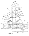
- FIG. 8 is a general cross-section view schematically illustrating a fifth preferred embodiment of a polychromatic projection display system in accordance with the present invention based on a Michelson interferometer principle, including three light sources and three GLV arrays, one thereof for each of red, green and blue primary color components, corresponding light sources and GLVs being optically connected by two corresponding Philips prism arrangements, and each of the light sources having a dedicated collimating lens.
- a Michelson interferometer principle including three light sources and three GLV arrays, one thereof for each of red, green and blue primary color components, corresponding light sources and GLVs being optically connected by two corresponding Philips prism arrangements, and each of the light sources having a dedicated collimating lens.
- FIGS 9A and 9B are general cross-section views schematically illustrating two ray-trace aspects of a sixth preferred embodiment of a polychromatic projection display system in accordance with the present invention based on a wavefront-shearing interferometer principle.
- FIG 10 is a general cross-section view schematically illustrating angular shearing of spherical wavefronts by a wavefront-shearing optical arrangement in the system of FIGS 9A and 9B.
- FIGS 11A and 11B are general cross-section views schematically illustrating interferential combination of laterally-sheared, plane, phase-modulated wavefronts in the system of FIGS 9A and 9B.
- FIG. 12 is a general cross-section view schematically illustrating one aspect of a preferred embodiment of a scanning, monochromatic display system in accordance with the present invention based on a Michelson interferometer principle.
- FIG. 12A is a general cross-section view, seen generally in the direction 12-12 of FIG. 12, schematically illustrating another aspect the scanning, monochromatic display system of FIG. 12, wherein the system is arranged for direct viewing.
- FIG. 12A is a general cross-section view, seen generally in the direction 12-12 of FIG. 12, schematically illustrating yet another aspect of the scanning, monochromatic display system of FIG. 12, wherein the system is arranged for projecting a real image on a screen or the like.
- a particularly preferred light modulating device is a reflective grating light-valve (GLV) array.
- GLV reflective grating light-valve
- Use of such devices in real two-dimensional arrays for making displays has been proposed, and devices are described in detail in U.S. Patent No. 5,459,610.
- This type of reflective grating light-valve array is capable of providing displays of very high resolution, by virtue of very small feature or element size, very high switching speeds, and high bandwidth.
- FIG. 1 illustrates a portion 10 of a reflective grating light-valve array, which, for reasons of scale, is not depicted in its entirity.
- GLV array 10 includes rows of individually moveable elongated members or ribbons 12 including a reflective coating 14 (see FIG. 2). Ribbons 12 in a non-operated state (see FIG. 2) are suspended (in tension) over a base 16 in a plane 17 parallel thereto. Ribbons 12 are spaced apart and parallel to each other. Laterally aligned with spaces between members 12, and having about the same spacing thereas, are fixed reflective-members 18, formed by depositing a reflective coating on base 16. Fixed reflective-members can be defined as lying in a plane 19 parallel to base 16.
- GLV array 10 is fabricated using lithographic semiconductor device fabrication techniques on a silicon (wafer) substrate 20.
- Base 16 is one surface of the wafer.
- An electrode layer 22 is deposited on an opposite surface of the wafer.
- Ribbons 12 and fixed reflective-members preferably have a width between about one and four micrometers ( ⁇ m) and a length between about 40.0 ⁇ m and 100.0 ⁇ m.
- a GLV array suitable for use in a two-dimensional display in accordance with the present invention preferably has a width of about (Q) centimeter (cm), and a height of about (Q). Such an array would include about (Q) moveable members 12, per row, and a number of rows corresponding to the number of lines in the image to be displayed.
- the narrow width of the fixed and moveable members is such that a group of adjacent members, for example, a group of eight fixed and moveable member pairs, can be used to represent one image-element or pixel, in one of two-hundred-fifty-six grey shades, while still providing a pixel small enough to provide resolution comparable to a conventional CRT computer monitor.
- a ribbon 12 is moved or operated by applying a potential between the member and base 16.
- the distance between reflective coating 14 of the moveable member, and a corresponding (adjacent) fixed member 18, is set to one-half wavelength of light which is used to illuminate the array (see FIG. 2).
- a ribbon 12 When a sufficient potential is applied, a ribbon 12 is deflected towards and can be held on base 16.
- the thickness of ribbons 12 is selected such that in this "operated and held” state, the distance between reflective surfaces of corresponding fixed and moveable members is one-quarter wavelength of light which is used to illuminate the array (see FIG. 3). In this state, destructive interference between light reflected from moveable and fixed members creates diffracted wavefronts (not shown). In the present invention however, the diffracted wavefronts are not of interest, image information being derived from the effect of the moveable elements in phase modulating an incident "perfect” or phase-constant wavefront 24.
- Any adjacent pair of moveable and fixed members 12 and 18, or any functional group of such pairs, representing all or part of an image element, may be considered to be a "light-valve". It is from this consideration that the terminology grating light-valve array is adopted for purposes of this description.
- ribbons 12 move through planes parallel to base 16 (or any grating plane) in states between the extreme states illustrated in FIGS 2 and 3. Intermediate states may be used to operate the members in an analog manner.
- System 30 includes a light source 32 preferably a "monochromatic" light source, for example, a semiconductor light emitting device such as a light emitting diode or laser.
- a light source 32 preferably a "monochromatic" light source, for example, a semiconductor light emitting device such as a light emitting diode or laser.
- monochromatic here meaning that light emitted from source 32 is restricted to wavelengths in a narrow band around a nominal center wavelength, the band being sufficiently narrow that it will have no significant adverse effect on optical interference between co-propagating wavefronts, on which principle systems in accordance with the present invention are based.
- Light 36 from source 32 is collimated by lens 40 and can be thus described as having been formed into a perfect plane or "phase-constant" wavefront indicated whimsically in FIG. 4 by broken line 24.
- Phase-constant here, meaning that all points on the wavefront are essentially in-phase with each other.
- Practitioners of the optical art will recognize that essentially, here, means that phase-constancy is only possible to a degree permitted by the optical accuracy of optical elements forming or directing the wavefront.
- Lens 40 is illustrated in FIG. 4, for simplicity as a single element. Those familiar with the optical art will recognize however that lens 40 typically would include two or more elements.
- Wavefront 24 (collimated light 36) then enters an optical arrangement 42 including a GLV array 10, a reference mirror 43, and a cube-beamsplitter 44 having a forty-five degree reflecting surface 46.
- Surface 46 includes a filter coating (not shown) which partially transmits and partially reflects light 36. Transmission and reflection are preferably arranged to be about equal. This partial transmission and partial transmission of light 36 can be defined as dividing wavefront 24 into two portions.
- the reflected portion as indicated by arrows 36R is incident on GLV 10.
- the transmitted portion as indicated by arrows 36T is incident on reference mirror 43.
- Reference mirror 43 has a reflecting surface (not specifically indicated in FIG. 4) which is preferably sufficiently flat that it does not significantly aberrate the phase of a wavefront incident thereon.
- a phase-constant reference wavefront 24R reflected from mirror 43 and surface 46 emerges from beamsplitter cube 44.
- mirror 43 could be replaced by reflectively coating the face of beamsplitter cube 44 to which it
- phase-modulated wavefront 24M emerges from beamsplitter cube 44 and propagates along a system axis 48 together with phase-constant, reference wavefront 24R.
- image 54 which is an interference pattern or interferogram image of GLV 10, wherein bright or dark portions are representative of the operating state of moveable members 12 of the GLV.
- image 54 can be made to represent essentially any video or graphic image, whether directly generated by the software or transformed thereby from a separate video source, such as a camera or VCR.
- image as used in this description and appended claims should be interpreted as meaning an image at any instant in time, except where that is clearly not the case. This recognizes the fact that so-called “moving” images and many “still” images are formed from a rapidly presented sequence of such instantaneous images, and avoids tedious and unecessary repetition of that fact.
- system 30 is initially "calibrated” with GLV 10 in a state when all moveable members thereof are in one extreme position or the other.
- this state is a state in which moveable elements are all "up”, i.e., no potential is applied (see FIG. 2).
- moveable elements are all "up", i.e., no potential is applied (see FIG. 2).
- fixed and moveable reflective-members are separated by one-half wavelength, leading to a round trip phase change of one wavelength between portions of a wavefront incident on moveable and fixed reflective-members.
- wavefront 24M would appear to be a phase-constant wavefront, as is wavefront 24R.
- image 54 can be made to appear all dark or all bright respectively. If, for example, an "all dark" condition is selected, subsequent operation of GLV 10 to provide a graphic or video image will produce an image consisting or bright dots on a dark background.
- image forming optics 52 include lenses 56 and 58. As in the case of lens 40, these lenses are illustrated for simplicity as single elements, but would, in practice, each include two or more elements.
- GLV 10 can be considered an object and any individual member of GLV 10 or point thereon can be considered as emitting a cone of rays by broken lines 37 diverging as they leave the GLV. GLV 10 is placed in a focal plane of lens 56, such that rays 37 are collimated after passing through the lens.
- Paraxial rays 36A viz., those rays which collectively are reflected from GLV 10 and reference mirror 43 are brought to a focus by lens 56 at an exit pupil 53 thereof and then diverge toward lens 58 and then are redirected toward screen 50 by lens 58.
- Lens 58 brings rays 37 to a focus on screen 50.
- Real image 54 on screen 50 can be viewed by a viewer at any convenient location with respect to the screen as illustrated by eye 60R.
- system 30 is described above as a projection system with optical arrangement 52 for projecting a real image 54 on screen 50, the system can be arranged for direct viewing by simply omitting lens 58 from optical arrangement 52.
- This is illustrated (system 31) in FIG. 5, wherein optical arrangement 52A now includes only lens 56, and a viewers eye 60V, placed at or close to pupil 53 and directed toward the lens, would see an interferential combination of virtual images (at infinity) of wavefronts 24R and 24M. This interferential combination of virtual images would represent the image to be displayed by system 31 in virtual form.
- FIG. 6 One such polychromatic display system 70 is illustrated in FIG. 6.
- light 36P from polychromatic source 32P is collimated by lens 40.
- Light 36P includes all primary color components, i.e. , red, green, and blue.
- Lens 40 directs a plane wavefront 24P, including all of these primary color components, into an optical arrangement 42P.
- Optical arrangement 42P includes a beamsplitter cube 44 having a forty-five degree, partially-reflective, partially-transmissive, surface 46.
- a reference mirror 43 is adjacent beamsplitter cube 44 as described above for monochromatic system 30.
- Each GLV array of course, is constructed in the same manner as GLV 10 of system 30.
- Each GLV is individually adjustable for providing image "calibration", as discussed above for system 30.
- Surface 76 of prism arrangement 72 is filter coated to reflect red and transmit blue and green.
- Surface 78 of prism arrangement 72 is filter coated to reflect green and transmit blue.
- prism arrangement 72 as a well-known, Philips-prism arrangement.
- the objective of prism arrangement 72 is to place each of GLV arrays 10R, 10G, and 10B at the same optical distance from entrance/exit surface 80 of the prism arrangement.
- Philips-prism arrangement 72 is but one of several such arrangements which can achieve this objective, and which would be known by one skilled in the art. Accordingly, prism arrangement 72, should not be construed as limiting the present invention.
- GLV arrays 10R, 10G, and 10B are illuminated by, respectively, collimated beams 36PRR, 36PRG, and 36 PRB.
- the GLV arrays provide red, green, and blue diverging beams 37R, 37G, and 37B. This creates three (red, green and blue respectively) phase-modulated wavefronts 24MR, 24MG, and 24MB to be imaged by imaging optics 52.
- a polychromatic, phase-constant, reference wavefront 24RP is created by reflection of a portion of light 36P from reference mirror 43 and surface 46 of beamsplitter cube 44.
- Imaging optics 52 are arranged, as discussed above with reference to system 30, to image wavefronts 24MR, 24MG, 24MB, and 24RP as real images onto a screen (not shown in FIG. 6, but implied by eye 60R) where they interferentially combine to form the polychromatic image to be displayed as a real image.
- optical arrangement 52 may include only lens 56, and a viewer's eye 60V may directly view a virtual interferential combination of wavefronts 24MR, 24MG, 24MB, and 24RP representing the polychromatic image to be displayed as virtual image.
- System 71 is essentially identical in configuration to above-described system 70, with the exception that polychromatic light source 32P has been replaced by three separate, monochromatic, red, green, and blue light sources 32R, 32G, and 32B respectively. Red 36R, green 36G, and blue 36B light from theses sources is directed by a Philips-prism arrangement 72 into lens 40 for collimation. Polychromatic, phase-constant wavefront 24P emerges from lens 40. Those skilled in the optical art will recognize, of course that polychromatic wavefront 24P can also be regarded as separate, phase-constant red, green and blue wavefronts, while preserving the interferometric principle of the present invention.
- collimated light from lenses 40R, 40G, and 40B is directed into a Philips-prism arrangement 72, and combined to form a collimated polychromatic light output indicated in FIG. 8 as polychromatic, phase-constant, wavefront 24P.
- This wavefront can also be considered as separate, phase-constant red, green and blue wavefronts while preserving the interferometric principle of the present invention.
- any of the above-described display systems can be regarded as an imaging Michelson- interferometer, in which an optical surface being "tested” is the surface of GLV array 10.
- FIGS 9A and 9B an embodiment 80 of a polychromatic projection display system employing a wavefront-shearing interferometer principle is illustrated.
- system 80 differs from foregoing embodiments only in the interferometric principle involved, common components of the systems are not described in detail. Only those components and ray-trace aspects necessary for an understanding how the wavefront-shearing interferometric principle is applied are described in detail. Rays of only one primary color (blue) are traced, as rays of other primary colors will behave and interact in exactly the same manner.
- wavefronts 24MR, 24MG and 24MB Reflected from GLVs 10R, 10G and 10B will be phase- modulated, but otherwise plane, wavefronts 24MR, 24MG and 24MB (see FIG. 9A). These wavefronts copropagate along axis 48 and are directed into projection optics 52 which include lenses 56 and 58 having the same function as in above-described projection systems, and which, likewise, practically will be multi-element lenses.
- Wavefront dividing and shearing arrangement 82 consisting of a beamsplitter cube 84 a fixed mirror 86 (which could, of course, be a coated face of the cube) and an adjustable mirror 88 which can be moved axially, and tilted in two orthogonal axes.
- Wavefront division is accomplished by forty-five degree surface 83, which has a partially-transmitting, partially-reflecting filter coating (not shown).
- lens 56 is preferably configured such that, in space 88 between beamsplitter cube 84 and lens 58, wavefronts propagating along axis 48 (here "folded" ninety degrees by surface 83) are spherical, however, still phase-modulated.
- the result of tilting mirror 88 with respect to mirror 86 is that spherical phase-modulated wavefronts 24MS1 and 24MS2 emanating from each (represented by rays 90 and 91 only in FIG. 9A) appear to be angularly sheared by an angle X with respect to one another, while still being essentially in the same (spherical plane).
- Lens 58 includes one or more field-flattening elements (not shown) such that after wavefronts 24MS1 and 24MS2 are passed through the lens they are flattened to provide a pair of corresponding, parallel, blue, phase-modulated wavefronts 24MB1 and 24MB2. These wavefronts are then imaged onto screen 50, as indicated in FIG. 9B by traced rays 37, 37B1 and 37B2, to interferentially combine and form a polychromatic image.
- Wavefronts 24MB1 and 24MB2 are laterally sheared with respect to each other by an distance Y. This distance is made some whole multiple, preferably one, of the spacing between moveable members 12 of the GLVs. The manner in which phase-modulated wavefronts 24MB1 and 24MB2 interferentially combine is next described with reference to FIGS 11A and 11B.
- each of wavefronts 24MB1 and 24MB2 includes fixed portions 25F and phase-modulated portions 25M corresponding to fixed and moveable reflective-members 18 and 12 of GLV 10B.
- each fixed portion of one wavefront will align with a phase-modulated portion of the other.
- Each fixed and phase-modulated aligned pair of wavefront portions will in effect be a microscopic interferometer and will provide an image element having a brightness determined by the phase relationship between the pair.
- any one of the wavefronts can be considered as acting as a reference wavefront for the other.
- a superposition of wavefronts 24MB1 and 24MB2 can also be regarded as forming two other wavefronts, one 27MB of which is phase-modulated, and the other 27RB of which is a phase-constant reference wavefront.
- Inteferential combination of wavefronts 27MB and 27RB provides the blue portion of the polychromatic image on screen 50.
- the polychromatic image can be regarded as being formed from red, green, and blue pairs of wavefronts. Interferential combination of the red, green and blue wavefront pairs forms respectively red, green and blue, primary color portions of the polychromatic image.
- the two dimensional array includes a plurality of rows of moveable and fixed reflective-members, at least one row representing one row or line of picture elements (pixels) for each such line in the image.
- Each pixel as noted above may be represented by one or a plurality of moveable members.
- a scanning arrangement must be provided for scanning an interferometrically- generated image (real or virtual) through the field of view of a viewer.
- the GLV array is operated cooperatively with a drive unit for the scanning means, such that the array sequentially represents sequential lines of the image to be displayed.
- a one-dimensional GLV would require N x B moveable elements, where B is the number of data bits per pixel.
- the one-dimensional GLV array would typically be modulated M times in a single scan to sequentially represent the M display lines.
- FIGS 12 and 12A illustrate a system 90 which is essentially identical with above-described system 31 (see FIG. 5), with the exception that in system 90 a one-dimensional GLV 10R is employed, rather than the two-dimensional GLV 10 of system 31. Images are formed by the system by interferential combination of phase-modulated and phase-constant wavefronts 24M and 24R respectively. Because an image formed is one-dimensional, a scanning arrangement 92 is provided for scanning the one-dimensional image as discussed above. Scanning arrangement 92 includes a scanning mirror 94 which is reciprocally, angularly scanned about an axis 96 by a drive motor 98, as indicated in FIG. 12 by arrow C. Scanning mirror 94 is preferably placed proximate exit pupil 53 on lens 56.
- Angular scanning of mirror 94 causes a virtual image of GLV array 10R (indicated whimsically in FIG. 12 by broken rectangle 99V) to be scanned linearly across the field of view of a viewer 60V as indicated by arrow D.
- An electronic processor 100 for converting video data from a source 102 thereof to a form useable by a GLV array, cooperatively operates moving members of GLV 10 and scan-drive motor 98 for causing the one-dimensional image to represent sequential display lines.
- FIG 12B a system 91 is illustrated which is essentially identical with system 90 of FIG. 12A with the exception that a projection lens 58 is added for projecting a one dimensional real image 99R on screen 50.
- Angular scanning of mirror 94 here, causes image 99R to be swept across screen 50 through the field of view of a viewer 60R as indicated by arrow D.
- scanning systems 90 and 91 have been depicted in a simple form, based respectively on the monochromatic, Michelson-interferometer-based, two-dimensional systems 31 and 30 of FIGS 5 and FIG 4. This has been done to highlight the scanning aspect of the systems and to avoid unnecessary repetition of polychromatic light-handling and interferometer aspects already described in detail. It will be evident to one skilled in the optical art, however, that the scanning principles described are applicable to any of the above-described two-dimensional systems or variations of those systems, as the interferometric image forming aspects of the systems are independent of whether the GLV array has one or two usable dimensions.
- reflective scanning arrangement 92 is but one of several well-known scanning arrangements, that may be employed. Any such scanning system may be used, more or less effectively, without departing from the spirit and scope of the present invention.
- display systems employing a planar GLV array as a spatial light-modulator for representing an image to be displayed have been described.
- the systems rely for image representation on the phase-position of moveable reflective elements of the GLV array, which move through planes parallel to the plane of the array.
- the moveable elements provide, from a phase-constant wavefront incident thereon, a reflected phase-modulated wavefront representing the image to be displayed.
- the displayed image is provided by interferentially combining the phase-modulated wavefront with a reference wavefront also formed, directly or indirectly, from the incident phase-constant wavefront.
Landscapes
- Physics & Mathematics (AREA)
- Engineering & Computer Science (AREA)
- Multimedia (AREA)
- Signal Processing (AREA)
- General Physics & Mathematics (AREA)
- Optics & Photonics (AREA)
- Mechanical Light Control Or Optical Switches (AREA)
- Transforming Electric Information Into Light Information (AREA)
- Video Image Reproduction Devices For Color Tv Systems (AREA)
Claims (20)
- System für die Wiedergabe eines Bildes, enthaltend:gekennzeichnet durch:zumindest eine ebene Gitterlichtventil-(GLV)-Anordnung (10, 10R, 10G, 10B), welche zumindest eine Reihe an langgestreckten, voneinander beabstandeten, parallel ausgerichteten bewegbaren Reflexionselementen (14) enthält, wobei jedes der bewegbaren Reflexionselemente (14) individuell gegenüber der Gitterebene durch hierzu parallel verlaufende Ebenen in einem Maße bewegbar ist, welches einem Element des wiederzugebenden Bildes entspricht,Bildinterferometer (42, 42P) zum Erzeugen eines Interferogrammbildes des zumindest einen GLV-Anordnungs, wobei das Interferogrammbild zumindest einen Abschnitt des wiederzugebenden Bildes zu jedem Zeitpunkt wiedergibt.
- System nach Anspruch 1,
bei dem das Bildinterferometer entsprechend dem Michelson-Interferometerprinzip angeordnet ist. - System nach Anspruch 1,
bei dem in der GLV-Anordnung eine Reihe von voneinander beabstandeten, ortsfesten Reflexionselementen (18) in jeder Reihe der bewegbaren Reflexionselemente (14) vorgesehen ist und bei dem die ortsfesten Reflexionselemente (18) in einer Ebene angeordnet sind, die parallel zu der Gitterebene verläuft, zueinander den gleichen Abstand haben wie die bewegbaren Reflexionselemente (14) und seitlich so angeordnet sind, dass sich jedes ortsfeste Reflexionselement in einer Position zwischen benachbarten, bewegbaren Reflexionselementen befindet, und bei dem das Bildwiedergabe-Interferometermittel entsprechend dem Weilenfrontscher-Interferometerprinzip angeordnet ist. - System für die Wiedergabe eines Bildes, enthaltend:wobei jedes bewegbare Reflexionselement (14) individuell gegenüber einer Gitterebene über Ebenen, die parallel zu der Gitterebene verlaufen, in einem Maße bewegbar ist, welches einem Element des wiederzugebenden Bildes entspricht, gekennzeichnet durch:eine planare Gitterlichtventil-(GLV)-Anordnung (10, 10R, 10G, 10B), die mehrere Reihen an langgestreckten, voneinander beabstandeten, parallel zueinander ausgerichteten und bewegbaren Reflexionselemente (14) enthält,wobei die zweiten und die dritten optischen Mittel in der Weise angeordnet sind, dass das erste und das zweite Bild zusammen durch Interferenz das wiederzugebende Bild bereitstellen.erste optische Mittel (40, 40R, 40G, 40B) zum Bereitstellen einer ersten phasenkonstanten optischen Wellenfront;zweite optische Mittel (42, 42P, 82) zum Umformen der ersten optischen Wellenfront in eine zweite optische Wellenfront, welche durch die bewegbaren Reflexionselemente (14) der GLV-Anordnung räumlich phasenmoduliert ist, undin eine dritte phasenkonstante optische Wellenfront;dritte optische Mittel (52) zum Erzeugen eines ersten und eines zweiten Bildes der zweiten und dritten optischen Wellenfront; und
- System nach Anspruch 4,
bei dem die zweite und die dritte optische Wellenfront durch Aufteilen der ersten optischen Wellenfront in zwei Abschnitte und durch Reflexion eines der Abschnitte aus der GLV-Anordnung, um die zweite optische Wellenfront bereit zu stellen, und durch Reflektieren des anderen Abschnitts von einem Referenzspiegel (43), um die dritte optische Wellenfront bereitzustellen, geschaffen werden. - System nach Anspruch 4 oder 5,
bei dem die erste, die zweite und die dritte Wellenfront ebene Wellenfronten sind. - System nach Anspruch 4. 5 oder 6,
bei dem in der GLV-Anordnung eine Reihe von voneinander beabstandeten, ortsfesten Reflexionselementen (18) in jeder Reihe der bewegbaren Reflexionselemente (14) vorgesehen ist und bei dem die ortsfesten Reflexionselemente (18) in einer Ebene angeordnet sind, die parallel zu Gitterebene verläuft, voneinander den gleichen Abstand haben wie die bewegbaren Reflexionselemente (14) und seitlich so angeordnet sind, dass sich jedes ortsfeste Reflexionselement in einer Position zwischen benachbarten bewegbaren Reflexionselementen befindet. - System nach Anspruch 4,
bei dem in der GLV-Anordnung eine Reihe von voneinander beabstandeten, ortsfesten Reflexionselementen (18) in jeder Reihe der bewegbaren Reflexionselemente (14) vorgesehen ist, wobei die ortsfesten Reflexionselemente (18) in einer Ebene, die parallel zur Gitterebene verläuft, angeordnet sind, voneinander den gleichen Abstand haben wie die bewegbaren Reflexionselemente (14) und seitlich so angeordnet sind, dass sich jedes ortsfeste Reflexionselement in einer Position zwischen benachbarten, bewegbaren Reflexionselementen befindet, und
wobei das zweite optische Mittel (82) bewirkt, dass die erste optische Wellenfront von der GLV-Anordnung (10, 10R, 10G, 10B) reflektiert wird, anschließend in zwei komplexe optische Wellenfronten aufgeteilt wird, von denen jede einen phasenkonstanten Abschnitt und einen phasenmodulierten Abschnitt entsprechend den ortsfesten bzw. den bewegbaren Reflexionselementen der GLV-Anordnung enthält, und bei dem das zweite optische Mittel bewirkt, dass die komplexen optischen Wellenfronten sich axial und seitlich voneinander um eine Strecke gleich einem ganzzahligen Vielfachen des Abstandes zwischen den Reflexionselementen beabstandet ausbreiten, so dass die phasenmodulierten Abschnitte der beiden komplexen Wellenfronten zusammen die zweite reflektierte Wellenfront bilden und die phasenkonstanten Abschnitte der beiden komplexen Wellenfronten zusammen die dritte reflektierte Wellenfront bilden. - System zum Wiedergeben eines Bildes, enthaltend:wobei das zweite und das dritte optische Mittel in der Weise angeordnet sind, dass das erste und das zweite Bild durch Interferenz zusammen das wiederzugebende Bild bereitstellen.eine Gitterlichtventil-(GLV)-Anordnung (10, 10R, 10G, 10B), welche mehrere Reihen an langgestreckten, voneinander beabstandeten, parallel ausgerichteten, bewegbaren Reflexionselementen (14) enthält, wobei jedes bewegbare Reflexionselement individuell gegenüber einer Gitterebene durch Ebenen, die parallel zu der Gitterebene verlaufen, in einem Maße bewegbar ist, welches einem wiederzugebenden Bildelement entspricht, wobei eine Reihe an ortsfesten voneinander beabstandeten Reflexionselementen (18) in jeder Reihe bewegbarer Reflexionselemente vorgesehen ist, und wobei die ortsfesten Reflexionselemente in einer Ebene parallel zu der Gitterebene angeordnet sind, voneinander den gleichen Abstand haben wie die bewegbaren Reflexionselemente und seitlich so angeordnet sind, dass sie sich jeweils zwischen benachbarten bewegbaren Reflexionselementen befinden, gekennzeichnet durcherste optische Mittel (40 40R, 40G, 40B) zum Bereitstellen einer ersten phasenkonstanten optischen Wellenfront;zweite optische Mittel (82), um zu bewirken, dass die erste optische Wellenfront von der GLV-Anordnung reflektiert wird, anschließend in zwei komplexe optische Wellenfronten aufgeteilt wird, von denen jede einen phasenkonstanten und einen phasenmodulierten Abschnitt entsprechend den ortsfesten bzw. den bewegbaren Reflexionselementen der GLV-Anordnung enthält, und dass die beiden komplexen optischen Wellenfronten sich koaxial, seitlich voneinander um eine Strecke beabstandet, die ein ganzzahliges Vielfaches des Abstandes zwischen den Reflexionselementen ist, in der Weise auszubreiten, dass die phasenmodulierten Abschnitte der zwei komplexen optischen Wellenfronten zusammen die zweite optische Wellenfront, welche räumlich durch die bewegbaren Reflexionselemente der GLV-Anordnung moduliert wird, bilden, und dass die phasenkonstanten Abschnitte der zwei komplexen Wellenfronten zusammen eine dritte phasenkonstante optische Wellenfront bilden, unddritte optische Mittel (52), um ein erstes und ein zweites Bild der zweiten und der dritten optischen Wellenfront zu bilden; und
- System zum Anzeigen eines Mehrfarbenbildes, enthaltend:wobei das zweite und das dritte optische Mittel in der Weise angeordnet sind, dass das erste, das zweite, das dritte und das vierte Bild durch Interferenz zusammen das wiederzugebende Mehrfarbenbild bereitstellen.eine erste, eine zweite und eine dritte ebene Gitterlichtventil-(GLV)-Anordnung (10R, 10G, 10B) zum Bearbeiten der roten, grünen und blauen Grundfarbenanteile des wiederzugebenden Bildes, wobei jede GLV-Anordnung mehrere Reihen an langgestreckten, voneinander beabstandeten, parallel ausgerichteten, bewegbaren Reflexionselementen enthält, von denen jedes einzeln gegenüber einer Gitterebene durch Ebenen, welche parallel zur Gitterebene verlaufen, in dem Maß bewegbar ist, das einem wiederzugebenden Bildelement entspricht;einen Referenzspiegel (43);eine Quelle (32P, 32R, 32G, 32B) an Mehrfarbenlicht, welches Wellenlängen entsprechend den roten, grünen und blauen Anteilen des wiederzugebenen Bildes enthält;erste optische Mittel (40, 40R, 40G, 40B) zum Bereitstellen aus der Quelle an Mehrfarbenlicht einer ersten phasenkonstanten optischen Wellenfront, wobei die erste optische Wellenfront die roten, grünen und blauen Farbanteile enthält;zweite optische Mittel (42P) zum Erzeugen eines ersten Abschnittes der ersten optischen Wellenfront in rot, grün und blau, wobei zweite optische Wellenfronten durch die bewegbaren Reflexionselemente der ersten bzw. der zweiten und der dritten GLV-Anordnung räumlich phasenmoduliert sind, undzum Reflektieren eines zweiten Abschnitts der ersten optischen Wellenfront an dem Referenzsiegel, um eine dritte phasenkonstante optische Wellenfront zu erzeugen;dritte optische Mittel (52) zum Erzeugen eines ersten, eines zweiten, eines dritten und eines vierten Bildes der roten, grünen und blauen zweiten optischen Wellenfronten und der dritten optischen Wellenfront; und
- System nach Anspruch 10,
bei dem die Mehrfarbenlichtquelle getrennte rote, grüne und blaue monochromatische Lichtquellen (32R, 32G, 32B) enthält, deren abgestrahltes Licht durch eine Anordnung dichroitischer Filter (74R, 74G, 74B) kombiniert wird, um ein polychromatisches Licht bereitstellen. - System zum Wiedergeben eines polychromatischen Bildes, enthaltend:der grünen bzw. der blauen zweiten optischen Wellenfront und der roten bzw. der grünen bzw. der blauen dritten optischen Wellenfront,eine erste, eine zweite und eine dritte ebene Gitterlichtventil-(GLV)-Anordnung (10R, 10G, 10B) zum Bearbeiten der roten, grünen und blauen Grundfarbenanteile des wiederzugebenden Bildes, wobei jede dieser Anordnungen mehrere Reihen an langgestreckten, voneinander beabstandeten, parallel ausgerichteten, bewegbaren Reflexionselementen enthält, von denen jedes einzeln gegenüber eine Gitterebene durch Ebenen, welche parallel zu der Gitterebene verlaufen, um ein Maß bewegbar ist, welches einem wiederzugebenden Bildelement entspricht, wobei eine Reihe von voneinander beabstandeten feststehenden Reflexionselementen in jeder Reihe bewegbarer Reflexionselemente vorgesehen ist, und wobei die ortsfesten Reflexionselemente in einer Ebene, welche parallel zur Gitterebene verläuft, angeordnet sind, voneinander den gleichen Abstand haben wie die bewegbaren Reflexionselemente und seitlich so angeordnet sind, dass jedes ortsfeste Reflexionselement sich zwischen benachbarten bewegbaren Reflexionselementen befindet;eine Quelle an polychromatischem Licht (32P, 32R, 32G, 32B), welches Wellenlängen enthält, die den roten, grünen und blauen Anteilen des wiederzugebenden Bildes entsprechen;erste optische Mittel (40, 40R, 40G, 40B) zum Bereitstellen aus der Quelle für polychromatisches Licht einer ersten phasenkonstanten polychromatischen optischen Wellenfront, die rote, grüne und blaue Farbanteile enthält;zweite optische Mittel (82) zum Aufteilen der ersten polychromatischen optischen Wellenfront in getrennte rote, grüne und blaue erste optische Wellenfronten, um zu bewirken, dass die roten, grünen und blauen ersten optischen Wellenfronten von der ersten, der zweiten und der dritten GLV-Anordnung reflektiert werden, um jede der reflektierten roten, grünen und blauen ersten optischen Wellenfronten in ein Paar komplexer optischer Wellenfronten aufzuteilen, die phasenkonstante und phasenmodulierte Abschnitte entsprechend den ortsfesten bzw. bewegbaren Reflexionselementen der GLV-Anordnung enthalten, und um zu bewirken, dass das Paar komplexer Wellenfronten sich koaxial, seitlich voneinander um ein ganzzahliges Vielfaches des Abstandes zwischen den Reflexionselementen beabstandet auszubreiten, dass die phasenmodulierten Abschnitte der roten, grünen und blauen komplexen optischen Wellenfrontenpaare zusammen eine rote bzw. eine grüne bzw. eine blaue zweite optische Wellenfront bilden, die durch die bewegbaren Reflexionselemente der ersten bzw. der zweiten bzw. der dritten GLV-Anordnung räumlich moduliert werden, und dass die phasenkonstanten Abschnitte der roten, grünen und blauen komplexen optischen Wellenfrontenpaare zusammen die rote bzw. die grüne bzw. die blaue dritte phasenkonstante optische Wellenfront bilden;dritte optische Mittel (52) zum Erzeugen eines ersten, eines zweiten, eines dritten, eines vierten, eines fünften und eines sechsten Bildes der roten bzw.
wobei das zweite und das dritte optische Mittel so angeordnet sind, dass das erste, das zweite, das dritte, das vierte, das fünfte und das sechste Bild durch Interferenz zusammen das wiederzugebende polychromatische Bild bereitstellen. - System nach Anspruch 12,
bei dem die polychromatische Lichtquelle getrennte rote, grüne und blaue monochromatische Lichtquellen enthält, wobei das abgestrahlte Licht durch eine Anordnung an optischen Filtern kombiniert wird, um das polychromatische Licht bereitzustellen. - System zum Wiedergeben eines Bildes, enthaltend:wobei das zweite und das dritte optische Mittel in der Weise angeordnet sind, dass das erste und das zweite Bild durch Interferenz zusammen das wiederzugebende Bild bereitstellen.eine Gitterlichtventil-(GLV)-Anordnung (10, 10R, 10G, 10B), welche mehrere Reihen von langgestreckten, voneinander beabstandeten, parallel zueinander ausgerichteten bewegbaren Reflexionselementen (14) enthält, von denen jedes einzeln gegenüber einer Gitterebene durch Ebenen, welche parallel zur Gitterebene verlaufen, in einem Maße bewegbar ist, welches einem wiederzugebenden Bildelement entspricht, wobei eine Reihe von ortsfesten, voneinander beabstandeten Reflexionselementen (18) in jeder Reihe bewegbarer Reflexionselemente vorgesehen sind, in einer Ebene, welche parallel zur Gitterebene ist, angeordnet sind voneinander gleich beabstandet wie die bewegbaren Reflexionselemente und seitlich so angeordnet sind, das jedes sich in einer Position zwischen benachbarten bewegbaren Reflexionselementen befindet, gekennzeichnet durch:erste optische Mittel (40, 40R, 40G, 40B), um eine erste phasenkonstante optische Wellenfront bereit zu stellen;zweite optische Mittel (82), um zu bewirken, dass die erste optische Wellenfront an der GLV-Anordnung reflektiert und anschließend in eine zweite und eine dritte optische Wellenfront aufgeteilt wird, von denen jede phasenkonstante und phasenmodulierte Abschnitte entsprechend den ortsfesten bzw. den bewegbaren Reflexionselementen der GLV-Anordnung enthält, und dass die erste und die zweite optische Wellenfront sich koaxial, seitlich voneinander um ein ganzzahliges Vielfaches des Abstandes zwischen den Reflexionselementen beabstandet ausbreiten, unddritte optische Mittel (52) zum Erzeugen eines ersten und eines zweiten Bildes der zweiten bzw. der dritten optischen Wellenfront;
- System zum Wiedergeben eines zweidimensionalen Bildes, welches mehrere Zeilen an Bildelementen enthält, wobei das System aufweist:eine Gitterlichtventil-(GLV)-Anordnung (10, 10R, 10G, 10B), die eine Reihe langgestreckter, voneinander beabstandeter, parallel ausgerichteter bewegbarer Reflexionselemente enthält, von denen jedes einzeln gegenüber einer Gitterebene durch Ebenen, die parallel zu der Gitterebene verlaufen, um ein Maß bewegbar ist, welches einem Element einer Zeile eines wiederzugebenden Bildes entspricht;erste optische Mittel (40, 40R, 40G, 40B) zum Bereitstellen einer ersten phasenkonstanten optischen Wellenfront;zweite optische Mittel (42, 42P) zum Umformen der ersten optischen Wellenfront in eine zweite optische Wellenfront, die durch die bewegbaren Reflexionselemente der GLV-Anordnung räumlich phasenmoduliert wird, und in eine dritte phasenkonstante optische Wellenfront;dritte optische Mittel (52) zum Erzeugen eines ersten und eines zweiten Bildes der zweiten bzw. der dritten optischen Wellenfront;wobei das zweite und das dritte optische Mittel in der Weise angeordnet sind, dass das erste und das zweite Bild durch Interferenz zusammen eine Bildzeile des wiederzugebenden Bildes bereitstellen;elektronische Mittel zum Betätigen der bewegbaren Elemente in der Weise, dass die Bildzeile aufeinanderfolgend alle Zeilen des wiederzugebenden Bildes repräsentiert; undAbtastmittel (92), welche mit den dritten optischen Mitteln und den elektronischen Mitteln zusammenwirken, um die Bildzeile quer durch das Gesichtsfeld des Betrachters in der Weise zu bewegen, dass die sich bewegende Bildzeile dem Betrachter als zweidimensionales Bild erscheint.
- System nach einem der Ansprüche 4 bis 15,
bei dem das erste und das zweite Bild reale Bilder sind, welche auf eine Betrachtungsoberfläche projiziert werden, die für einen Betrachter sichtbar ist. - System nach einem der Ansprüche 4 bis 15,
bei dem das erste und das zweite Bild virtuelle Bilder sind, die durch einen Betrachter direkt über das dritte optische Mittel gesehen werden können. - System zum Wiedergeben eines Bildes an einen Betrachter, enthaltend:zumindest eine ebene Gitterlichtventil-(GLV)-Anordnung (10, 10R, 10G, 10B), welche eine Reihe langgestreckter, voneinander beabstandeter, parallel zueinander ausgerichteter bewegbarer Reflexionselemente enthält, von denen jedes einzeln gegenüber der Gitterebene durch Ebenen, welche parallel zur Gitterebene verlaufen, um ein Maß bewegbar ist, welches einem Element des wiederzugebenden Bildes entspricht; undMittel zum Überstreichen (42, 42P, 92) einer Folge von Interferogrammbildern der GLV-Anordnung durch das Betrachtungsfeld des Betrachters.
- System nach Anspruch 18,
bei dem die Interferogrammbilder reale Bilder sind, die auf eine Betrachtungsoberfläche projiziert werden. - System nach Anspruch 18,
bei dem die Interferogrammbilder virtuelle Bilder sind, die über optische Mittel durch den Betrachter betrachtet werden, welche in dem System zum Erzeugen der Interfereogrammbilder ebthalten sind.
Applications Claiming Priority (3)
| Application Number | Priority Date | Filing Date | Title |
|---|---|---|---|
| US961826 | 1997-10-31 | ||
| US08/961,826 US6088102A (en) | 1997-10-31 | 1997-10-31 | Display apparatus including grating light-valve array and interferometric optical system |
| PCT/US1998/022341 WO1999023520A1 (en) | 1997-10-31 | 1998-10-22 | Display apparatus including grating light-valve array and interferometric optical system |
Publications (2)
| Publication Number | Publication Date |
|---|---|
| EP1027625A1 EP1027625A1 (de) | 2000-08-16 |
| EP1027625B1 true EP1027625B1 (de) | 2002-05-29 |
Family
ID=25505072
Family Applications (1)
| Application Number | Title | Priority Date | Filing Date |
|---|---|---|---|
| EP98953870A Expired - Lifetime EP1027625B1 (de) | 1997-10-31 | 1998-10-22 | Anzeigegerät mit einem gitter-lichtventilarray und interferometrisches optisches system |
Country Status (10)
| Country | Link |
|---|---|
| US (1) | US6088102A (de) |
| EP (1) | EP1027625B1 (de) |
| JP (1) | JP3288369B2 (de) |
| KR (1) | KR20010031675A (de) |
| CN (1) | CN1290356A (de) |
| AT (1) | ATE218214T1 (de) |
| AU (1) | AU1113399A (de) |
| DE (1) | DE69805645T2 (de) |
| NO (1) | NO20002235L (de) |
| WO (1) | WO1999023520A1 (de) |
Families Citing this family (129)
| Publication number | Priority date | Publication date | Assignee | Title |
|---|---|---|---|---|
| US6674562B1 (en) | 1994-05-05 | 2004-01-06 | Iridigm Display Corporation | Interferometric modulation of radiation |
| US6969635B2 (en) * | 2000-12-07 | 2005-11-29 | Reflectivity, Inc. | Methods for depositing, releasing and packaging micro-electromechanical devices on wafer substrates |
| US7907319B2 (en) | 1995-11-06 | 2011-03-15 | Qualcomm Mems Technologies, Inc. | Method and device for modulating light with optical compensation |
| KR100703140B1 (ko) | 1998-04-08 | 2007-04-05 | 이리다임 디스플레이 코포레이션 | 간섭 변조기 및 그 제조 방법 |
| US8928967B2 (en) | 1998-04-08 | 2015-01-06 | Qualcomm Mems Technologies, Inc. | Method and device for modulating light |
| US6872984B1 (en) | 1998-07-29 | 2005-03-29 | Silicon Light Machines Corporation | Method of sealing a hermetic lid to a semiconductor die at an angle |
| US6303986B1 (en) | 1998-07-29 | 2001-10-16 | Silicon Light Machines | Method of and apparatus for sealing an hermetic lid to a semiconductor die |
| US6962419B2 (en) | 1998-09-24 | 2005-11-08 | Reflectivity, Inc | Micromirror elements, package for the micromirror elements, and projection system therefor |
| US6721508B1 (en) | 1998-12-14 | 2004-04-13 | Tellabs Operations Inc. | Optical line terminal arrangement, apparatus and methods |
| US6501600B1 (en) | 1999-08-11 | 2002-12-31 | Lightconnect, Inc. | Polarization independent grating modulator |
| US6674563B2 (en) | 2000-04-13 | 2004-01-06 | Lightconnect, Inc. | Method and apparatus for device linearization |
| US6826330B1 (en) | 1999-08-11 | 2004-11-30 | Lightconnect, Inc. | Dynamic spectral shaping for fiber-optic application |
| WO2003007049A1 (en) | 1999-10-05 | 2003-01-23 | Iridigm Display Corporation | Photonic mems and structures |
| US6956878B1 (en) | 2000-02-07 | 2005-10-18 | Silicon Light Machines Corporation | Method and apparatus for reducing laser speckle using polarization averaging |
| US6888983B2 (en) | 2000-04-14 | 2005-05-03 | Lightconnect, Inc. | Dynamic gain and channel equalizers |
| US7018052B2 (en) * | 2000-08-30 | 2006-03-28 | Reflectivity, Inc | Projection TV with improved micromirror array |
| US6411425B1 (en) * | 2000-09-27 | 2002-06-25 | Eastman Kodak Company | Electromechanical grating display system with spatially separated light beams |
| US6476848B2 (en) | 2000-12-21 | 2002-11-05 | Eastman Kodak Company | Electromechanical grating display system with segmented waveplate |
| US7177081B2 (en) | 2001-03-08 | 2007-02-13 | Silicon Light Machines Corporation | High contrast grating light valve type device |
| US6614580B2 (en) * | 2001-04-10 | 2003-09-02 | Silicon Light Machines | Modulation of light out of the focal plane in a light modulator based projection system |
| US6707591B2 (en) | 2001-04-10 | 2004-03-16 | Silicon Light Machines | Angled illumination for a single order light modulator based projection system |
| JP3823751B2 (ja) * | 2001-04-17 | 2006-09-20 | ソニー株式会社 | 画像表示装置 |
| US7785098B1 (en) | 2001-06-05 | 2010-08-31 | Mikro Systems, Inc. | Systems for large area micro mechanical systems |
| CA2702143C (en) | 2001-06-05 | 2014-02-18 | Mikro Systems, Inc. | Methods for manufacturing three-dimensional devices and devices created thereby |
| US6865346B1 (en) | 2001-06-05 | 2005-03-08 | Silicon Light Machines Corporation | Fiber optic transceiver |
| US7141812B2 (en) * | 2002-06-05 | 2006-11-28 | Mikro Systems, Inc. | Devices, methods, and systems involving castings |
| US6782205B2 (en) | 2001-06-25 | 2004-08-24 | Silicon Light Machines | Method and apparatus for dynamic equalization in wavelength division multiplexing |
| US7023606B2 (en) * | 2001-08-03 | 2006-04-04 | Reflectivity, Inc | Micromirror array for projection TV |
| US6829092B2 (en) | 2001-08-15 | 2004-12-07 | Silicon Light Machines, Inc. | Blazed grating light valve |
| US6785001B2 (en) | 2001-08-21 | 2004-08-31 | Silicon Light Machines, Inc. | Method and apparatus for measuring wavelength jitter of light signal |
| US6930364B2 (en) | 2001-09-13 | 2005-08-16 | Silicon Light Machines Corporation | Microelectronic mechanical system and methods |
| US6956995B1 (en) | 2001-11-09 | 2005-10-18 | Silicon Light Machines Corporation | Optical communication arrangement |
| US7106490B2 (en) * | 2001-12-14 | 2006-09-12 | Micronic Laser Systems Ab | Methods and systems for improved boundary contrast |
| US6800238B1 (en) | 2002-01-15 | 2004-10-05 | Silicon Light Machines, Inc. | Method for domain patterning in low coercive field ferroelectrics |
| EP1335234B1 (de) * | 2002-02-06 | 2011-06-15 | Brother Kogyo Kabushiki Kaisha | Bildprojektionsvorrichtung |
| US20050202363A1 (en) * | 2002-02-21 | 2005-09-15 | Osterwalder J. M. | Dental imaging and treatment system |
| EP1483615A1 (de) * | 2002-03-01 | 2004-12-08 | Hentze-Lissotschenko Patentverwaltungs GmbH & Co.KG | Modulationsvorrichtung |
| US20030184531A1 (en) * | 2002-03-29 | 2003-10-02 | Sony Corporation | GLV engine for image display |
| US6947198B2 (en) * | 2002-03-29 | 2005-09-20 | Sony Corporation | Emissive image display apparatus |
| US6777861B2 (en) * | 2002-03-29 | 2004-08-17 | Sony Corporation | Color selector for emissive image display apparatus |
| US6861792B2 (en) * | 2002-03-29 | 2005-03-01 | Sony Corporation | Color separator for emissive display |
| US6788354B2 (en) | 2002-04-01 | 2004-09-07 | Sony Corporation | Method for making color separator for emissive display |
| US6728023B1 (en) | 2002-05-28 | 2004-04-27 | Silicon Light Machines | Optical device arrays with optimized image resolution |
| US6767751B2 (en) | 2002-05-28 | 2004-07-27 | Silicon Light Machines, Inc. | Integrated driver process flow |
| US6839479B2 (en) | 2002-05-29 | 2005-01-04 | Silicon Light Machines Corporation | Optical switch |
| US7054515B1 (en) | 2002-05-30 | 2006-05-30 | Silicon Light Machines Corporation | Diffractive light modulator-based dynamic equalizer with integrated spectral monitor |
| US6822797B1 (en) | 2002-05-31 | 2004-11-23 | Silicon Light Machines, Inc. | Light modulator structure for producing high-contrast operation using zero-order light |
| US6829258B1 (en) | 2002-06-26 | 2004-12-07 | Silicon Light Machines, Inc. | Rapidly tunable external cavity laser |
| US6813059B2 (en) | 2002-06-28 | 2004-11-02 | Silicon Light Machines, Inc. | Reduced formation of asperities in contact micro-structures |
| US6908201B2 (en) | 2002-06-28 | 2005-06-21 | Silicon Light Machines Corporation | Micro-support structures |
| US6714337B1 (en) | 2002-06-28 | 2004-03-30 | Silicon Light Machines | Method and device for modulating a light beam and having an improved gamma response |
| US6801354B1 (en) | 2002-08-20 | 2004-10-05 | Silicon Light Machines, Inc. | 2-D diffraction grating for substantially eliminating polarization dependent losses |
| US7057795B2 (en) | 2002-08-20 | 2006-06-06 | Silicon Light Machines Corporation | Micro-structures with individually addressable ribbon pairs |
| US6712480B1 (en) | 2002-09-27 | 2004-03-30 | Silicon Light Machines | Controlled curvature of stressed micro-structures |
| JP2004157522A (ja) * | 2002-10-17 | 2004-06-03 | Sony Corp | 画像生成装置、画像表示装置、画像表示方法、及び光変調素子調整装置 |
| US6947459B2 (en) * | 2002-11-25 | 2005-09-20 | Eastman Kodak Company | Organic vertical cavity laser and imaging system |
| WO2004049037A1 (ja) * | 2002-11-27 | 2004-06-10 | Brother Kogyo Kabushiki Kaisha | 画像表示装置 |
| US6928207B1 (en) | 2002-12-12 | 2005-08-09 | Silicon Light Machines Corporation | Apparatus for selectively blocking WDM channels |
| US7057819B1 (en) | 2002-12-17 | 2006-06-06 | Silicon Light Machines Corporation | High contrast tilting ribbon blazed grating |
| US6987600B1 (en) | 2002-12-17 | 2006-01-17 | Silicon Light Machines Corporation | Arbitrary phase profile for better equalization in dynamic gain equalizer |
| US6934070B1 (en) | 2002-12-18 | 2005-08-23 | Silicon Light Machines Corporation | Chirped optical MEM device |
| US6927891B1 (en) | 2002-12-23 | 2005-08-09 | Silicon Light Machines Corporation | Tilt-able grating plane for improved crosstalk in 1×N blaze switches |
| TWI289708B (en) | 2002-12-25 | 2007-11-11 | Qualcomm Mems Technologies Inc | Optical interference type color display |
| AU2003288663A1 (en) * | 2003-01-16 | 2004-08-10 | Koninklijke Philips Electronics N.V. | Device and method of scanning an image in a projection system |
| US7068372B1 (en) | 2003-01-28 | 2006-06-27 | Silicon Light Machines Corporation | MEMS interferometer-based reconfigurable optical add-and-drop multiplexor |
| US7286764B1 (en) | 2003-02-03 | 2007-10-23 | Silicon Light Machines Corporation | Reconfigurable modulator-based optical add-and-drop multiplexer |
| US6947613B1 (en) | 2003-02-11 | 2005-09-20 | Silicon Light Machines Corporation | Wavelength selective switch and equalizer |
| US6885494B2 (en) * | 2003-02-12 | 2005-04-26 | Reflectivity, Inc. | High angle micro-mirrors and processes |
| US7042622B2 (en) * | 2003-10-30 | 2006-05-09 | Reflectivity, Inc | Micromirror and post arrangements on substrates |
| US6922272B1 (en) | 2003-02-14 | 2005-07-26 | Silicon Light Machines Corporation | Method and apparatus for leveling thermal stress variations in multi-layer MEMS devices |
| US6806997B1 (en) | 2003-02-28 | 2004-10-19 | Silicon Light Machines, Inc. | Patterned diffractive light modulator ribbon for PDL reduction |
| US7391973B1 (en) | 2003-02-28 | 2008-06-24 | Silicon Light Machines Corporation | Two-stage gain equalizer |
| US7027202B1 (en) | 2003-02-28 | 2006-04-11 | Silicon Light Machines Corp | Silicon substrate as a light modulator sacrificial layer |
| US6829077B1 (en) | 2003-02-28 | 2004-12-07 | Silicon Light Machines, Inc. | Diffractive light modulator with dynamically rotatable diffraction plane |
| US7046420B1 (en) | 2003-02-28 | 2006-05-16 | Silicon Light Machines Corporation | MEM micro-structures and methods of making the same |
| US6922273B1 (en) | 2003-02-28 | 2005-07-26 | Silicon Light Machines Corporation | PDL mitigation structure for diffractive MEMS and gratings |
| US7042611B1 (en) | 2003-03-03 | 2006-05-09 | Silicon Light Machines Corporation | Pre-deflected bias ribbons |
| US6833854B1 (en) * | 2003-06-12 | 2004-12-21 | Micronic Laser Systems Ab | Method for high precision printing of patterns |
| KR101098070B1 (ko) | 2003-06-12 | 2011-12-26 | 마이크로닉 마이데이터 아베 | 고정밀도 패턴 인쇄 방법 |
| CN100549493C (zh) * | 2003-12-10 | 2009-10-14 | 硅光机器公司 | 二维空间光调制器 |
| US7342705B2 (en) | 2004-02-03 | 2008-03-11 | Idc, Llc | Spatial light modulator with integrated optical compensation structure |
| US7706050B2 (en) | 2004-03-05 | 2010-04-27 | Qualcomm Mems Technologies, Inc. | Integrated modulator illumination |
| US7855824B2 (en) | 2004-03-06 | 2010-12-21 | Qualcomm Mems Technologies, Inc. | Method and system for color optimization in a display |
| JP4375183B2 (ja) * | 2004-09-22 | 2009-12-02 | ウシオ電機株式会社 | マイクロチップ |
| US8362987B2 (en) | 2004-09-27 | 2013-01-29 | Qualcomm Mems Technologies, Inc. | Method and device for manipulating color in a display |
| US7807488B2 (en) | 2004-09-27 | 2010-10-05 | Qualcomm Mems Technologies, Inc. | Display element having filter material diffused in a substrate of the display element |
| US8004504B2 (en) * | 2004-09-27 | 2011-08-23 | Qualcomm Mems Technologies, Inc. | Reduced capacitance display element |
| US8031133B2 (en) * | 2004-09-27 | 2011-10-04 | Qualcomm Mems Technologies, Inc. | Method and device for manipulating color in a display |
| US7911428B2 (en) | 2004-09-27 | 2011-03-22 | Qualcomm Mems Technologies, Inc. | Method and device for manipulating color in a display |
| US7355780B2 (en) | 2004-09-27 | 2008-04-08 | Idc, Llc | System and method of illuminating interferometric modulators using backlighting |
| US7525730B2 (en) * | 2004-09-27 | 2009-04-28 | Idc, Llc | Method and device for generating white in an interferometric modulator display |
| US7710632B2 (en) | 2004-09-27 | 2010-05-04 | Qualcomm Mems Technologies, Inc. | Display device having an array of spatial light modulators with integrated color filters |
| US7928928B2 (en) | 2004-09-27 | 2011-04-19 | Qualcomm Mems Technologies, Inc. | Apparatus and method for reducing perceived color shift |
| US7813026B2 (en) | 2004-09-27 | 2010-10-12 | Qualcomm Mems Technologies, Inc. | System and method of reducing color shift in a display |
| US8102407B2 (en) * | 2004-09-27 | 2012-01-24 | Qualcomm Mems Technologies, Inc. | Method and device for manipulating color in a display |
| US7898521B2 (en) | 2004-09-27 | 2011-03-01 | Qualcomm Mems Technologies, Inc. | Device and method for wavelength filtering |
| US7286277B2 (en) * | 2004-11-26 | 2007-10-23 | Alces Technology, Inc. | Polarization light modulator |
| US7054051B1 (en) * | 2004-11-26 | 2006-05-30 | Alces Technology, Inc. | Differential interferometric light modulator and image display device |
| US7277216B2 (en) * | 2004-11-26 | 2007-10-02 | Alces Technology | Differential interferometric light modulator and image display system |
| US7446925B2 (en) * | 2004-11-26 | 2008-11-04 | Alces Technology | Micro-electromechanical light modulator with anamorphic optics |
| US7244028B2 (en) * | 2004-12-14 | 2007-07-17 | Coherent, Inc. | Laser illuminated projection displays |
| US7355657B2 (en) * | 2004-12-14 | 2008-04-08 | Coherent, Inc. | Laser illuminated projection displays |
| US7413311B2 (en) * | 2005-09-29 | 2008-08-19 | Coherent, Inc. | Speckle reduction in laser illuminated projection displays having a one-dimensional spatial light modulator |
| CN100468127C (zh) * | 2005-10-07 | 2009-03-11 | 鸿富锦精密工业(深圳)有限公司 | 投影显示装置 |
| KR100800709B1 (ko) * | 2005-10-10 | 2008-02-01 | 삼성전자주식회사 | 영상 스캔 장치 |
| US20070133635A1 (en) * | 2005-12-14 | 2007-06-14 | Samsung Electronics Co.; Ltd | Dual light source and laser projection display apparatus using same |
| US7916980B2 (en) | 2006-01-13 | 2011-03-29 | Qualcomm Mems Technologies, Inc. | Interconnect structure for MEMS device |
| US8004743B2 (en) | 2006-04-21 | 2011-08-23 | Qualcomm Mems Technologies, Inc. | Method and apparatus for providing brightness control in an interferometric modulator (IMOD) display |
| KR101628340B1 (ko) | 2006-10-06 | 2016-06-08 | 퀄컴 엠이엠에스 테크놀로지스, 인크. | 디스플레이 장치 및 디스플레이의 형성 방법 |
| EP2069838A2 (de) | 2006-10-06 | 2009-06-17 | Qualcomm Mems Technologies, Inc. | Beleuchtungsvorrichtung mit eingebautem lichtkoppler |
| US8872085B2 (en) | 2006-10-06 | 2014-10-28 | Qualcomm Mems Technologies, Inc. | Display device having front illuminator with turning features |
| US20080158263A1 (en) * | 2006-12-28 | 2008-07-03 | Texas Instruments Incorporated | System and method for increasing bit-depth in a display system |
| US8072402B2 (en) | 2007-08-29 | 2011-12-06 | Qualcomm Mems Technologies, Inc. | Interferometric optical modulator with broadband reflection characteristics |
| US8068710B2 (en) | 2007-12-07 | 2011-11-29 | Qualcomm Mems Technologies, Inc. | Decoupled holographic film and diffuser |
| WO2010036801A2 (en) | 2008-09-26 | 2010-04-01 | Michael Appleby | Systems, devices, and/or methods for manufacturing castings |
| CN101710202B (zh) * | 2009-11-13 | 2012-07-11 | 深圳超多维光电子有限公司 | 对位装置、采用所述对位装置的光栅对位系统及其对位方法 |
| US8848294B2 (en) | 2010-05-20 | 2014-09-30 | Qualcomm Mems Technologies, Inc. | Method and structure capable of changing color saturation |
| US8813824B2 (en) | 2011-12-06 | 2014-08-26 | Mikro Systems, Inc. | Systems, devices, and/or methods for producing holes |
| US9967546B2 (en) | 2013-10-29 | 2018-05-08 | Vefxi Corporation | Method and apparatus for converting 2D-images and videos to 3D for consumer, commercial and professional applications |
| US20150116458A1 (en) | 2013-10-30 | 2015-04-30 | Barkatech Consulting, LLC | Method and apparatus for generating enhanced 3d-effects for real-time and offline appplications |
| US10158847B2 (en) | 2014-06-19 | 2018-12-18 | Vefxi Corporation | Real—time stereo 3D and autostereoscopic 3D video and image editing |
| IL244180B (en) * | 2016-02-18 | 2022-02-01 | Oorym Optics Ltd | Dynamic full three dimensional display |
| CN107300824B (zh) * | 2016-04-15 | 2019-11-12 | 台达电子工业股份有限公司 | 光源模块 |
| US10742941B2 (en) * | 2016-11-30 | 2020-08-11 | Nec Corporation | Projection device, projection method, and program recording medium |
| CN106646884B (zh) * | 2016-12-30 | 2020-03-20 | 苏州苏大维格光电科技股份有限公司 | 一种投影物镜及三维显示装置 |
| CN106646885B (zh) * | 2016-12-30 | 2020-02-11 | 苏州苏大维格光电科技股份有限公司 | 一种投影物镜及三维显示装置 |
| JP6743985B2 (ja) * | 2018-02-09 | 2020-08-19 | ウシオ電機株式会社 | カラー画像表示装置、およびそれを用いたカラー画像複製物作成方法、その方法により作成されたカラー画像複製物 |
| EP4031831A1 (de) * | 2019-09-20 | 2022-07-27 | NDC Technologies Inc. | Laserinterferometriesysteme und verfahren |
| WO2022075553A1 (en) * | 2020-10-07 | 2022-04-14 | Samsung Electronics Co., Ltd. | Optical sensor device for determining distance to object and velocity of the object, and identifying the shape and structure of the object |
Family Cites Families (334)
| Publication number | Priority date | Publication date | Assignee | Title |
|---|---|---|---|---|
| US16767A (en) * | 1857-03-03 | Improved metallic roof | ||
| US25169A (en) * | 1859-08-23 | Shipper-gear for pulleys | ||
| USRE16767E (en) | 1927-10-11 | Charles prancis jenkins | ||
| USRE16757E (en) * | 1922-10-31 | 1927-10-04 | knight | |
| US1548262A (en) * | 1924-07-02 | 1925-08-04 | Freedman Albert | Manufacture of bicolored spectacles |
| US1814701A (en) * | 1930-05-31 | 1931-07-14 | Perser Corp | Method of making viewing gratings for relief or stereoscopic pictures |
| US2415226A (en) * | 1943-11-29 | 1947-02-04 | Rca Corp | Method of and apparatus for producing luminous images |
| US2991690A (en) * | 1953-09-04 | 1961-07-11 | Polaroid Corp | Stereoscopic lens-prism optical system |
| US2783406A (en) * | 1954-02-09 | 1957-02-26 | John J Vanderhooft | Stereoscopic television means |
| NL197714A (de) | 1954-06-01 | 1900-01-01 | ||
| US3553364A (en) * | 1968-03-15 | 1971-01-05 | Texas Instruments Inc | Electromechanical light valve |
| US3576394A (en) * | 1968-07-03 | 1971-04-27 | Texas Instruments Inc | Apparatus for display duration modulation |
| US3600798A (en) * | 1969-02-25 | 1971-08-24 | Texas Instruments Inc | Process for fabricating a panel array of electromechanical light valves |
| BE757764A (fr) * | 1969-10-21 | 1971-04-21 | Itt | Systeme d'exploration a l'etat solide |
| US3743507A (en) * | 1970-10-23 | 1973-07-03 | Rca Corp | Recording of a continuous tone focused image on a diffraction grating |
| US3802769A (en) * | 1972-08-28 | 1974-04-09 | Harris Intertype Corp | Method and apparatus for unaided stereo viewing |
| US4093346A (en) * | 1973-07-13 | 1978-06-06 | Minolta Camera Kabushiki Kaisha | Optical low pass filter |
| US3886310A (en) * | 1973-08-22 | 1975-05-27 | Westinghouse Electric Corp | Electrostatically deflectable light valve with improved diffraction properties |
| US3947105A (en) * | 1973-09-21 | 1976-03-30 | Technical Operations, Incorporated | Production of colored designs |
| US3896338A (en) * | 1973-11-01 | 1975-07-22 | Westinghouse Electric Corp | Color video display system comprising electrostatically deflectable light valves |
| US3969611A (en) * | 1973-12-26 | 1976-07-13 | Texas Instruments Incorporated | Thermocouple circuit |
| JPS5742849B2 (de) * | 1974-06-05 | 1982-09-10 | ||
| US4001663A (en) * | 1974-09-03 | 1977-01-04 | Texas Instruments Incorporated | Switching regulator power supply |
| US3935500A (en) * | 1974-12-09 | 1976-01-27 | Texas Instruments Incorporated | Flat CRT system |
| US4020381A (en) * | 1974-12-09 | 1977-04-26 | Texas Instruments Incorporated | Cathode structure for a multibeam cathode ray tube |
| US3935499A (en) * | 1975-01-03 | 1976-01-27 | Texas Instruments Incorporated | Monolythic staggered mesh deflection systems for use in flat matrix CRT's |
| US4017158A (en) * | 1975-03-17 | 1977-04-12 | E. I. Du Pont De Nemours And Company | Spatial frequency carrier and process of preparing same |
| US4012116A (en) * | 1975-05-30 | 1977-03-15 | Personal Communications, Inc. | No glasses 3-D viewer |
| US4034211A (en) * | 1975-06-20 | 1977-07-05 | Ncr Corporation | System and method for providing a security check on a credit card |
| US4084437A (en) * | 1975-11-07 | 1978-04-18 | Texas Instruments Incorporated | Thermocouple circuit |
| US4184700A (en) * | 1975-11-17 | 1980-01-22 | Lgz Landis & Gyr Zug Ag | Documents embossed with optical markings representing genuineness information |
| CH595664A5 (de) * | 1975-11-17 | 1978-02-15 | Landis & Gyr Ag | |
| US4127322A (en) * | 1975-12-05 | 1978-11-28 | Hughes Aircraft Company | High brightness full color image light valve projection system |
| CH594495A5 (de) * | 1976-05-04 | 1978-01-13 | Landis & Gyr Ag | |
| US4135502A (en) * | 1976-09-07 | 1979-01-23 | Donald Peck | Stereoscopic patterns and method of making same |
| US4139257A (en) * | 1976-09-28 | 1979-02-13 | Canon Kabushiki Kaisha | Synchronizing signal generator |
| US4067129A (en) * | 1976-10-28 | 1978-01-10 | Trans-World Manufacturing Corporation | Display apparatus having means for creating a spectral color effect |
| CH604279A5 (de) * | 1976-12-21 | 1978-08-31 | Landis & Gyr Ag | |
| US4093921A (en) * | 1977-03-17 | 1978-06-06 | Texas Instruments Incorporated | Microcomputer processing approach for a non-volatile TV station memory tuning system |
| US4093922A (en) * | 1977-03-17 | 1978-06-06 | Texas Instruments Incorporated | Microcomputer processing approach for a non-volatile TV station memory tuning system |
| CH616253A5 (de) * | 1977-06-21 | 1980-03-14 | Landis & Gyr Ag | |
| US4185891A (en) * | 1977-11-30 | 1980-01-29 | Grumman Aerospace Corporation | Laser diode collimation optics |
| US4389096A (en) * | 1977-12-27 | 1983-06-21 | Matsushita Electric Industrial Co., Ltd. | Image display apparatus of liquid crystal valve projection type |
| CH622896A5 (de) * | 1978-03-20 | 1981-04-30 | Landis & Gyr Ag | |
| US4256787A (en) * | 1978-05-03 | 1981-03-17 | Massachusetts Institute Of Technology | Orientation of ordered liquids and their use in devices |
| US4225913A (en) * | 1978-09-19 | 1980-09-30 | Texas Instruments Incorporated | Self-referencing power converter |
| US4338660A (en) * | 1979-04-13 | 1982-07-06 | Relational Memory Systems, Inc. | Relational break signal generating device |
| US4343535A (en) * | 1979-12-14 | 1982-08-10 | Hughes Aircraft Company | Liquid crystal light valve |
| US4327966A (en) * | 1980-02-25 | 1982-05-04 | Bell Telephone Laboratories, Incorporated | Variable attenuator for laser radiation |
| US4327411A (en) * | 1980-03-04 | 1982-04-27 | Bell Telephone Laboratories, Incorporated | High capacity elastic store having continuously variable delay |
| US4430584A (en) * | 1980-05-29 | 1984-02-07 | Texas Instruments Incorporated | Modular input/output system |
| US4454591A (en) * | 1980-05-29 | 1984-06-12 | Texas Instruments Incorporated | Interface system for bus line control |
| US4447881A (en) * | 1980-05-29 | 1984-05-08 | Texas Instruments Incorporated | Data processing system integrated circuit having modular memory add-on capacity |
| US4418397A (en) * | 1980-05-29 | 1983-11-29 | Texas Instruments Incorporated | Address decode system |
| US4443845A (en) * | 1980-06-26 | 1984-04-17 | Texas Instruments Incorporated | Memory system having a common interface |
| US4503494A (en) * | 1980-06-26 | 1985-03-05 | Texas Instruments Incorporated | Non-volatile memory system |
| US4361384A (en) * | 1980-06-27 | 1982-11-30 | The United States Of America As Represented By The Secretary Of The Army | High luminance miniature display |
| US4420717A (en) * | 1980-10-06 | 1983-12-13 | Texas Instruments Incorporated | Use of motor winding as integrator to generate sawtooth for switch mode current regulator |
| US4594501A (en) * | 1980-10-09 | 1986-06-10 | Texas Instruments Incorporated | Pulse width modulation of printhead voltage |
| JPS57122981U (de) * | 1981-01-27 | 1982-07-31 | ||
| US4440839A (en) * | 1981-03-18 | 1984-04-03 | United Technologies Corporation | Method of forming laser diffraction grating for beam sampling device |
| US4408884A (en) * | 1981-06-29 | 1983-10-11 | Rca Corporation | Optical measurements of fine line parameters in integrated circuit processes |
| US4571603A (en) * | 1981-11-03 | 1986-02-18 | Texas Instruments Incorporated | Deformable mirror electrostatic printer |
| US4571041A (en) * | 1982-01-22 | 1986-02-18 | Gaudyn Tad J | Three dimensional projection arrangement |
| FR2527385B1 (fr) | 1982-04-13 | 1987-05-22 | Suwa Seikosha Kk | Transistor a couche mince et panneau d'affichage a cristaux liquides utilisant ce type de transistor |
| US4484188A (en) * | 1982-04-23 | 1984-11-20 | Texas Instruments Incorporated | Graphics video resolution improvement apparatus |
| US4468725A (en) * | 1982-06-18 | 1984-08-28 | Texas Instruments Incorporated | Direct AC converter for converting a balanced AC polyphase input to an output voltage |
| US4492435A (en) * | 1982-07-02 | 1985-01-08 | Xerox Corporation | Multiple array full width electro mechanical modulator |
| JPS59117876A (ja) * | 1982-12-24 | 1984-07-07 | Seiko Epson Corp | パ−ソナル液晶映像表示器 |
| JPS602073A (ja) * | 1983-04-06 | 1985-01-08 | テキサス・インスツルメンツ・インコ−ポレイテツド | 交流変換装置及び方法 |
| US4655539A (en) * | 1983-04-18 | 1987-04-07 | Aerodyne Products Corporation | Hologram writing apparatus and method |
| CH661683A5 (de) * | 1983-09-19 | 1987-08-14 | Landis & Gyr Ag | Einrichtung zum praegen von reliefmustern hoher aufloesung. |
| US4561044A (en) * | 1983-09-22 | 1985-12-24 | Citizen Watch Co., Ltd. | Lighting device for a display panel of an electronic device |
| US4809078A (en) * | 1983-10-05 | 1989-02-28 | Casio Computer Co., Ltd. | Liquid crystal television receiver |
| FR2553893B1 (fr) * | 1983-10-19 | 1986-02-07 | Texas Instruments France | Procede et dispositif de detection d'une transition de la composante continue d'un signal periodique, notamment pour joncteur telephonique |
| JPS60127888A (ja) * | 1983-12-15 | 1985-07-08 | Citizen Watch Co Ltd | 液晶表示装置 |
| JPS60185918A (ja) * | 1984-03-05 | 1985-09-21 | Canon Inc | 光変調方法 |
| JPS60214684A (ja) * | 1984-04-10 | 1985-10-26 | Citizen Watch Co Ltd | 液晶テレビ装置 |
| CH664030A5 (de) * | 1984-07-06 | 1988-01-29 | Landis & Gyr Ag | Verfahren zur erzeugung eines makroskopischen flaechenmusters mit einer mikroskopischen struktur, insbesondere einer beugungsoptisch wirksamen struktur. |
| US4566935A (en) * | 1984-07-31 | 1986-01-28 | Texas Instruments Incorporated | Spatial light modulator and method |
| US4710732A (en) * | 1984-07-31 | 1987-12-01 | Texas Instruments Incorporated | Spatial light modulator and method |
| US4709995A (en) * | 1984-08-18 | 1987-12-01 | Canon Kabushiki Kaisha | Ferroelectric display panel and driving method therefor to achieve gray scale |
| US4596992A (en) * | 1984-08-31 | 1986-06-24 | Texas Instruments Incorporated | Linear spatial light modulator and printer |
| US5096279A (en) | 1984-08-31 | 1992-03-17 | Texas Instruments Incorporated | Spatial light modulator and method |
| US5061049A (en) | 1984-08-31 | 1991-10-29 | Texas Instruments Incorporated | Spatial light modulator and method |
| IT1176859B (it) * | 1984-10-05 | 1987-08-18 | Honeywell Inf Systems | Rubino e gruppo guida aghi per testina stampante ad aghi |
| JPS6188676A (ja) * | 1984-10-05 | 1986-05-06 | Citizen Watch Co Ltd | 液晶テレビ装置 |
| US4615595A (en) * | 1984-10-10 | 1986-10-07 | Texas Instruments Incorporated | Frame addressed spatial light modulator |
| US5281957A (en) | 1984-11-14 | 1994-01-25 | Schoolman Scientific Corp. | Portable computer and head mounted display |
| US4641193A (en) * | 1984-12-07 | 1987-02-03 | New York Institute Of Technology | Video display apparatus and method |
| US4772094A (en) * | 1985-02-05 | 1988-09-20 | Bright And Morning Star | Optical stereoscopic system and prism window |
| DE3605516A1 (de) | 1985-02-21 | 1986-09-04 | Canon K.K., Tokio/Tokyo | Optisches funktionselement sowie optische funktionsvorrichtung |
| US4866488A (en) | 1985-03-29 | 1989-09-12 | Texas Instruments Incorporated | Ballistic transport filter and device |
| US4623219A (en) * | 1985-04-15 | 1986-11-18 | The United States Of America As Represented By The Secretary Of The Navy | Real-time high-resolution 3-D large-screen display using laser-activated liquid crystal light valves |
| US4719507A (en) * | 1985-04-26 | 1988-01-12 | Tektronix, Inc. | Stereoscopic imaging system with passive viewing apparatus |
| US4751509A (en) * | 1985-06-04 | 1988-06-14 | Nec Corporation | Light valve for use in a color display unit with a diffraction grating assembly included in the valve |
| US4728185A (en) * | 1985-07-03 | 1988-03-01 | Texas Instruments Incorporated | Imaging system |
| JPH0535388Y2 (de) * | 1985-07-29 | 1993-09-08 | ||
| US5299037A (en) | 1985-08-07 | 1994-03-29 | Canon Kabushiki Kaisha | Diffraction grating type liquid crystal display device in viewfinder |
| US4698602A (en) * | 1985-10-09 | 1987-10-06 | The United States Of America As Represented By The Secretary Of The Air Force | Micromirror spatial light modulator |
| US5172262A (en) | 1985-10-30 | 1992-12-15 | Texas Instruments Incorporated | Spatial light modulator and method |
| JPS62119521A (ja) * | 1985-11-19 | 1987-05-30 | Canon Inc | 光学変調装置 |
| US4811210A (en) * | 1985-11-27 | 1989-03-07 | Texas Instruments Incorporated | A plurality of optical crossbar switches and exchange switches for parallel processor computer |
| US4744633A (en) * | 1986-02-18 | 1988-05-17 | Sheiman David M | Stereoscopic viewing system and glasses |
| US4803560A (en) * | 1986-02-21 | 1989-02-07 | Casio Computer Co., Ltd. | Liquid-crystal television receiver with cassette tape recorder |
| US4829365A (en) * | 1986-03-07 | 1989-05-09 | Dimension Technologies, Inc. | Autostereoscopic display with illuminating lines, light valve and mask |
| US4856869A (en) * | 1986-04-08 | 1989-08-15 | Canon Kabushiki Kaisha | Display element and observation apparatus having the same |
| GB2198867A (en) | 1986-12-17 | 1988-06-22 | Philips Electronic Associated | A liquid crystal display illumination system |
| US4807965A (en) * | 1987-05-26 | 1989-02-28 | Garakani Reza G | Apparatus for three-dimensional viewing |
| US4814759A (en) * | 1987-07-08 | 1989-03-21 | Clinicom Incorporated | Flat panel display monitor apparatus |
| US4934773A (en) | 1987-07-27 | 1990-06-19 | Reflection Technology, Inc. | Miniature video display system |
| US5003300A (en) | 1987-07-27 | 1991-03-26 | Reflection Technology, Inc. | Head mounted display for miniature video display system |
| US4859012A (en) | 1987-08-14 | 1989-08-22 | Texas Instruments Incorporated | Optical interconnection networks |
| US5142677A (en) | 1989-05-04 | 1992-08-25 | Texas Instruments Incorporated | Context switching devices, systems and methods |
| US5072418A (en) | 1989-05-04 | 1991-12-10 | Texas Instruments Incorporated | Series maxium/minimum function computing devices, systems and methods |
| US5155812A (en) | 1989-05-04 | 1992-10-13 | Texas Instruments Incorporated | Devices and method for generating and using systems, software waitstates on address boundaries in data processing |
| US5024494A (en) | 1987-10-07 | 1991-06-18 | Texas Instruments Incorporated | Focussed light source pointer for three dimensional display |
| HU197469B (en) | 1987-10-23 | 1989-03-28 | Laszlo Holakovszky | Spectacle like, wearable on head stereoscopic reproductor of the image |
| US5155604A (en) | 1987-10-26 | 1992-10-13 | Van Leer Metallized Products (Usa) Limited | Coated paper sheet embossed with a diffraction or holographic pattern |
| US4952925A (en) | 1988-01-25 | 1990-08-28 | Bernd Haastert | Projectable passive liquid-crystal flat screen information centers |
| US4956619A (en) | 1988-02-19 | 1990-09-11 | Texas Instruments Incorporated | Spatial light modulator |
| ATE69407T1 (de) | 1988-03-03 | 1991-11-15 | Landis & Gyr Betriebs Ag | Dokument. |
| JPH01265293A (ja) | 1988-04-15 | 1989-10-23 | Sharp Corp | 小型表示装置 |
| JPH01296214A (ja) | 1988-05-25 | 1989-11-29 | Canon Inc | 表示装置 |
| US4827391A (en) * | 1988-06-01 | 1989-05-02 | Texas Instruments Incorporated | Apparatus for implementing output voltage slope in current mode controlled power supplies |
| JPH01306886A (ja) | 1988-06-03 | 1989-12-11 | Canon Inc | 体積位相型回折格子 |
| JP2585717B2 (ja) | 1988-06-03 | 1997-02-26 | キヤノン株式会社 | 表示装置 |
| US4856863A (en) * | 1988-06-22 | 1989-08-15 | Texas Instruments Incorporated | Optical fiber interconnection network including spatial light modulator |
| US5048077A (en) | 1988-07-25 | 1991-09-10 | Reflection Technology, Inc. | Telephone handset with full-page visual display |
| US5028939A (en) | 1988-08-23 | 1991-07-02 | Texas Instruments Incorporated | Spatial light modulator system |
| US5058992A (en) | 1988-09-07 | 1991-10-22 | Toppan Printing Co., Ltd. | Method for producing a display with a diffraction grating pattern and a display produced by the method |
| ATE98795T1 (de) | 1988-09-30 | 1994-01-15 | Landis & Gyr Business Support | Beugungselement. |
| US4915463A (en) | 1988-10-18 | 1990-04-10 | The United States Of America As Represented By The Department Of Energy | Multilayer diffraction grating |
| JPH07121097B2 (ja) | 1988-11-18 | 1995-12-20 | 株式会社日立製作所 | 液晶テレビおよびその製造方法 |
| US4982184A (en) | 1989-01-03 | 1991-01-01 | General Electric Company | Electrocrystallochromic display and element |
| US5162787A (en) | 1989-02-27 | 1992-11-10 | Texas Instruments Incorporated | Apparatus and method for digitized video system utilizing a moving display surface |
| US5287096A (en) | 1989-02-27 | 1994-02-15 | Texas Instruments Incorporated | Variable luminosity display system |
| US5214420A (en) | 1989-02-27 | 1993-05-25 | Texas Instruments Incorporated | Spatial light modulator projection system with random polarity light |
| US5214419A (en) | 1989-02-27 | 1993-05-25 | Texas Instruments Incorporated | Planarized true three dimensional display |
| US5206629A (en) | 1989-02-27 | 1993-04-27 | Texas Instruments Incorporated | Spatial light modulator and memory for digitized video display |
| KR100202246B1 (ko) | 1989-02-27 | 1999-06-15 | 윌리엄 비. 켐플러 | 디지탈화 비디오 시스템을 위한 장치 및 방법 |
| US5128660A (en) | 1989-02-27 | 1992-07-07 | Texas Instruments Incorporated | Pointer for three dimensional display |
| US5079544A (en) | 1989-02-27 | 1992-01-07 | Texas Instruments Incorporated | Standard independent digitized video system |
| US5446479A (en) | 1989-02-27 | 1995-08-29 | Texas Instruments Incorporated | Multi-dimensional array video processor system |
| US5272473A (en) | 1989-02-27 | 1993-12-21 | Texas Instruments Incorporated | Reduced-speckle display system |
| US5192946A (en) | 1989-02-27 | 1993-03-09 | Texas Instruments Incorporated | Digitized color video display system |
| US5170156A (en) | 1989-02-27 | 1992-12-08 | Texas Instruments Incorporated | Multi-frequency two dimensional display system |
| US4978202A (en) | 1989-05-12 | 1990-12-18 | Goldstar Co., Ltd. | Laser scanning system for displaying a three-dimensional color image |
| US5060058A (en) | 1989-06-07 | 1991-10-22 | U.S. Philips Corporation | Modulation system for projection display |
| US5022750A (en) | 1989-08-11 | 1991-06-11 | Raf Electronics Corp. | Active matrix reflective projection system |
| JPH0343682U (de) | 1989-09-06 | 1991-04-24 | ||
| GB8921722D0 (en) | 1989-09-26 | 1989-11-08 | British Telecomm | Micromechanical switch |
| US4954789A (en) | 1989-09-28 | 1990-09-04 | Texas Instruments Incorporated | Spatial light modulator |
| JP2508387B2 (ja) | 1989-10-16 | 1996-06-19 | 凸版印刷株式会社 | 回折格子パタ―ンを有するディスプレイの作製方法 |
| US5037173A (en) | 1989-11-22 | 1991-08-06 | Texas Instruments Incorporated | Optical interconnection network |
| US5142303A (en) | 1989-12-21 | 1992-08-25 | Texas Instruments Incorporated | Printing system exposure module optic structure and method of operation |
| US5041851A (en) | 1989-12-21 | 1991-08-20 | Texas Instruments Incorporated | Spatial light modulator printer and method of operation |
| US5101236A (en) | 1989-12-21 | 1992-03-31 | Texas Instruments Incorporated | Light energy control system and method of operation |
| US5237340A (en) | 1989-12-21 | 1993-08-17 | Texas Instruments Incorporated | Replaceable elements for xerographic printing process and method of operation |
| US5105369A (en) | 1989-12-21 | 1992-04-14 | Texas Instruments Incorporated | Printing system exposure module alignment method and apparatus of manufacture |
| US5072239A (en) | 1989-12-21 | 1991-12-10 | Texas Instruments Incorporated | Spatial light modulator exposure unit and method of operation |
| DE4001448C1 (de) | 1990-01-19 | 1991-07-11 | Mercedes-Benz Aktiengesellschaft, 7000 Stuttgart, De | |
| JPH03217814A (ja) | 1990-01-24 | 1991-09-25 | Canon Inc | 液晶プロジェクター |
| US5113272A (en) | 1990-02-12 | 1992-05-12 | Raychem Corporation | Three dimensional semiconductor display using liquid crystal |
| US5121231A (en) | 1990-04-06 | 1992-06-09 | University Of Southern California | Incoherent/coherent multiplexed holographic recording for photonic interconnections and holographic optical elements |
| US5291473A (en) | 1990-06-06 | 1994-03-01 | Texas Instruments Incorporated | Optical storage media light beam positioning system |
| US5502481A (en) | 1992-11-16 | 1996-03-26 | Reveo, Inc. | Desktop-based projection display system for stereoscopic viewing of displayed imagery over a wide field of view |
| US5165013A (en) | 1990-09-26 | 1992-11-17 | Faris Sadeg M | 3-D stereo pen plotter |
| JP2622185B2 (ja) | 1990-06-28 | 1997-06-18 | シャープ株式会社 | カラー液晶表示装置 |
| US5018256A (en) | 1990-06-29 | 1991-05-28 | Texas Instruments Incorporated | Architecture and process for integrating DMD with control circuit substrates |
| DE69113150T2 (de) | 1990-06-29 | 1996-04-04 | Texas Instruments Inc | Deformierbare Spiegelvorrichtung mit aktualisiertem Raster. |
| US5216537A (en) | 1990-06-29 | 1993-06-01 | Texas Instruments Incorporated | Architecture and process for integrating DMD with control circuit substrates |
| US5083857A (en) | 1990-06-29 | 1992-01-28 | Texas Instruments Incorporated | Multi-level deformable mirror device |
| US5142405A (en) | 1990-06-29 | 1992-08-25 | Texas Instruments Incorporated | Bistable dmd addressing circuit and method |
| US5099353A (en) | 1990-06-29 | 1992-03-24 | Texas Instruments Incorporated | Architecture and process for integrating DMD with control circuit substrates |
| US5291317A (en) | 1990-07-12 | 1994-03-01 | Applied Holographics Corporation | Holographic diffraction grating patterns and methods for creating the same |
| US5121343A (en) | 1990-07-19 | 1992-06-09 | Faris Sadeg M | 3-D stereo computer output printer |
| US5182665A (en) | 1990-09-07 | 1993-01-26 | Displaytech, Inc. | Diffractive light modulator |
| US5148157A (en) | 1990-09-28 | 1992-09-15 | Texas Instruments Incorporated | Spatial light modulator with full complex light modulation capability |
| US5113285A (en) | 1990-09-28 | 1992-05-12 | Honeywell Inc. | Full color three-dimensional flat panel display |
| US5331454A (en) | 1990-11-13 | 1994-07-19 | Texas Instruments Incorporated | Low reset voltage process for DMD |
| US5231363A (en) | 1990-11-26 | 1993-07-27 | Texas Instruments Incorporated | Pulse width modulating producing signals centered in each cycle interval |
| US5181231A (en) | 1990-11-30 | 1993-01-19 | Texas Instruments, Incorporated | Non-volatile counting method and apparatus |
| US5151718A (en) | 1990-12-31 | 1992-09-29 | Texas Instruments Incorporated | System and method for solid state illumination for dmd devices |
| US5105207A (en) | 1990-12-31 | 1992-04-14 | Texas Instruments Incorporated | System and method for achieving gray scale DMD operation |
| US5172161A (en) | 1990-12-31 | 1992-12-15 | Texas Instruments Incorporated | Unibody printing system and process |
| US5105299A (en) | 1990-12-31 | 1992-04-14 | Texas Instruments Incorporated | Unfolded optics for multiple row deformable mirror device |
| US5159485A (en) | 1990-12-31 | 1992-10-27 | Texas Instruments Incorporated | System and method for uniformity of illumination for tungsten light |
| CA2060057C (en) | 1991-01-29 | 1997-12-16 | Susumu Takahashi | Display having diffraction grating pattern |
| US5151724A (en) | 1991-01-30 | 1992-09-29 | Dan Kikinis | Dynamic holographic display with cantilever |
| US5299298A (en) | 1991-02-28 | 1994-03-29 | Hewlett-Packard Company | Accelerated shadow testing method for three dimensional graphics rendering system |
| US5178728A (en) | 1991-03-28 | 1993-01-12 | Texas Instruments Incorporated | Integrated-optic waveguide devices and method |
| CA2063744C (en) | 1991-04-01 | 2002-10-08 | Paul M. Urbanus | Digital micromirror device architecture and timing for use in a pulse-width modulated display system |
| US5347378A (en) | 1991-04-04 | 1994-09-13 | Displaytech, Inc. | Fast switching color filters for frame-sequential video using ferroelectric liquid crystal color-selective filters |
| US5148506A (en) | 1991-04-26 | 1992-09-15 | Texas Instruments Incorporated | Optical crossbar switch |
| US5226099A (en) | 1991-04-26 | 1993-07-06 | Texas Instruments Incorporated | Digital micromirror shutter device |
| US5170269A (en) | 1991-05-31 | 1992-12-08 | Texas Instruments Incorporated | Programmable optical interconnect system |
| US5155778A (en) | 1991-06-28 | 1992-10-13 | Texas Instruments Incorporated | Optical switch using spatial light modulators |
| US5221982A (en) | 1991-07-05 | 1993-06-22 | Faris Sadeg M | Polarizing wavelength separator |
| US5179274A (en) | 1991-07-12 | 1993-01-12 | Texas Instruments Incorporated | Method for controlling operation of optical systems and devices |
| US5287215A (en) | 1991-07-17 | 1994-02-15 | Optron Systems, Inc. | Membrane light modulation systems |
| US5170283A (en) | 1991-07-24 | 1992-12-08 | Northrop Corporation | Silicon spatial light modulator |
| US5168406A (en) | 1991-07-31 | 1992-12-01 | Texas Instruments Incorporated | Color deformable mirror device and method for manufacture |
| US5240818A (en) | 1991-07-31 | 1993-08-31 | Texas Instruments Incorporated | Method for manufacturing a color filter for deformable mirror device |
| CA2075026A1 (en) | 1991-08-08 | 1993-02-09 | William E. Nelson | Method and apparatus for patterning an imaging member |
| US5245686A (en) | 1991-09-06 | 1993-09-14 | Faris Sadeg M | Method of fabricating an image plane translator device and apparatus incorporating such device |
| US5307056A (en) | 1991-09-06 | 1994-04-26 | Texas Instruments Incorporated | Dynamic memory allocation for frame buffer for spatial light modulator |
| US5255100A (en) | 1991-09-06 | 1993-10-19 | Texas Instruments Incorporated | Data formatter with orthogonal input/output and spatial reordering |
| US5254980A (en) | 1991-09-06 | 1993-10-19 | Texas Instruments Incorporated | DMD display system controller |
| DE4133524C2 (de) | 1991-10-10 | 1996-08-29 | Fissler Gmbh | Dampfdruckkochtopf |
| CA2081753C (en) | 1991-11-22 | 2002-08-06 | Jeffrey B. Sampsell | Dmd scanner |
| US5231432A (en) | 1991-12-03 | 1993-07-27 | Florida Atlantic University | Projector utilizing liquid crystal light-valve and color selection by diffraction |
| EP0545412A3 (en) | 1991-12-05 | 1993-11-03 | Texas Instruments Inc | Method and apparatus to improve a video signal |
| US5231388A (en) | 1991-12-17 | 1993-07-27 | Texas Instruments Incorporated | Color display system using spatial light modulators |
| US5212555A (en) | 1991-12-17 | 1993-05-18 | Texas Instruments Incorporated | Image capture with spatial light modulator and single-cell photosensor |
| US5311349A (en) | 1991-12-18 | 1994-05-10 | Texas Instruments Incorporated | Unfolded optics for multiple row spatial light modulators |
| US5247593A (en) | 1991-12-18 | 1993-09-21 | Texas Instruments Incorporated | Programmable optical crossbar switch |
| CA2084923A1 (en) | 1991-12-20 | 1993-06-21 | Ronald E. Stafford | Slm spectrometer |
| US5202785A (en) | 1991-12-20 | 1993-04-13 | Texas Instruments Incorporated | Method and device for steering light |
| US5233456A (en) | 1991-12-20 | 1993-08-03 | Texas Instruments Incorporated | Resonant mirror and method of manufacture |
| CA2085961A1 (en) | 1991-12-23 | 1993-06-24 | William E. Nelson | Method and apparatus for steering light |
| US5247180A (en) | 1991-12-30 | 1993-09-21 | Texas Instruments Incorporated | Stereolithographic apparatus and method of use |
| US5285407A (en) | 1991-12-31 | 1994-02-08 | Texas Instruments Incorporated | Memory circuit for spatial light modulator |
| US5296950A (en) | 1992-01-31 | 1994-03-22 | Texas Instruments Incorporated | Optical signal free-space conversion board |
| US5504514A (en) | 1992-02-13 | 1996-04-02 | Texas Instruments Incorporated | System and method for solid state illumination for spatial light modulators |
| US5212582A (en) | 1992-03-04 | 1993-05-18 | Texas Instruments Incorporated | Electrostatically controlled beam steering device and method |
| EP0562424B1 (de) | 1992-03-25 | 1997-05-28 | Texas Instruments Incorporated | Eingebautes optisches Eichsystem |
| US5312513A (en) | 1992-04-03 | 1994-05-17 | Texas Instruments Incorporated | Methods of forming multiple phase light modulators |
| US5319214A (en) | 1992-04-06 | 1994-06-07 | The United States Of America As Represented By The Secretary Of The Army | Infrared image projector utilizing a deformable mirror device spatial light modulator |
| GB9208705D0 (en) | 1992-04-22 | 1992-07-22 | Smiths Industries Plc | Head-mounted display assemblies |
| US5459592A (en) | 1992-04-24 | 1995-10-17 | Sharp Kabushiki Kaisha | Projection display system including a collimating tapered waveguide or lens with the normal to optical axis angle increasing toward the lens center |
| US5311360A (en) | 1992-04-28 | 1994-05-10 | The Board Of Trustees Of The Leland Stanford, Junior University | Method and apparatus for modulating a light beam |
| US6219015B1 (en) * | 1992-04-28 | 2001-04-17 | The Board Of Directors Of The Leland Stanford, Junior University | Method and apparatus for using an array of grating light valves to produce multicolor optical images |
| GB2267579A (en) | 1992-05-15 | 1993-12-08 | Sharp Kk | Optical device comprising facing lenticular or parallax screens of different pitch |
| US5307185A (en) | 1992-05-19 | 1994-04-26 | Raychem Corporation | Liquid crystal projection display with complementary color dye added to longest wavelength imaging element |
| US5347433A (en) | 1992-06-11 | 1994-09-13 | Sedlmayr Steven R | Collimated beam of light and systems and methods for implementation thereof |
| US5281887A (en) | 1992-06-15 | 1994-01-25 | Engle Craig D | Two independent spatial variable degree of freedom wavefront modulator |
| US5315418A (en) | 1992-06-17 | 1994-05-24 | Xerox Corporation | Two path liquid crystal light valve color display with light coupling lens array disposed along the red-green light path |
| US5486841A (en) | 1992-06-17 | 1996-01-23 | Sony Corporation | Glasses type display apparatus |
| US5256869A (en) | 1992-06-30 | 1993-10-26 | Texas Instruments Incorporated | Free-space optical interconnection using deformable mirror device |
| US5430524A (en) | 1992-07-22 | 1995-07-04 | Texas Instruments Incorporated | Unibody printing and copying system and process |
| US5321416A (en) | 1992-07-27 | 1994-06-14 | Virtual Research Systems | Head-mounted visual display apparatus |
| US5327286A (en) | 1992-08-31 | 1994-07-05 | Texas Instruments Incorporated | Real time optical correlation system |
| US5348619A (en) | 1992-09-03 | 1994-09-20 | Texas Instruments Incorporated | Metal selective polymer removal |
| US5325116A (en) | 1992-09-18 | 1994-06-28 | Texas Instruments Incorporated | Device for writing to and reading from optical storage media |
| GB9220412D0 (en) | 1992-09-28 | 1992-11-11 | Texas Instruments Holland | Transponder systems for automatic identification purposes |
| US5285196A (en) | 1992-10-15 | 1994-02-08 | Texas Instruments Incorporated | Bistable DMD addressing method |
| US5289172A (en) | 1992-10-23 | 1994-02-22 | Texas Instruments Incorporated | Method of mitigating the effects of a defective electromechanical pixel |
| GB2272555A (en) | 1992-11-11 | 1994-05-18 | Sharp Kk | Stereoscopic display using a light modulator |
| DE59309409D1 (de) | 1992-11-20 | 1999-04-08 | Ascom Tech Ag | Lichtmodulator |
| US5450088A (en) | 1992-11-25 | 1995-09-12 | Texas Instruments Deutschland Gmbh | Transponder arrangement |
| US5410315A (en) | 1992-12-08 | 1995-04-25 | Texas Instruments Incorporated | Group-addressable transponder arrangement |
| US5420655A (en) | 1992-12-16 | 1995-05-30 | North American Philips Corporation | Color projection system employing reflective display devices and prism illuminators |
| KR100285696B1 (ko) | 1992-12-16 | 2001-09-17 | 윌리엄 비. 켐플러 | 패터닝된 금속층의 세정방법 |
| US5357369A (en) | 1992-12-21 | 1994-10-18 | Geoffrey Pilling | Wide-field three-dimensional viewing system |
| US5418584A (en) | 1992-12-31 | 1995-05-23 | Honeywell Inc. | Retroreflective array virtual image projection screen |
| US5371618A (en) | 1993-01-05 | 1994-12-06 | Brite View Technologies | Color liquid crystal display employing dual cells driven with an EXCLUSIVE OR relationship |
| AU5306494A (en) | 1993-01-08 | 1994-07-14 | Richard A Vasichek | Magnetic keeper accessory for wrench sockets |
| US5371543A (en) | 1993-03-03 | 1994-12-06 | Texas Instruments Incorporated | Monolithic color wheel |
| US5293511A (en) | 1993-03-16 | 1994-03-08 | Texas Instruments Incorporated | Package for a semiconductor device |
| US5435876A (en) | 1993-03-29 | 1995-07-25 | Texas Instruments Incorporated | Grid array masking tape process |
| US5455602A (en) | 1993-03-29 | 1995-10-03 | Texas Instruments Incorporated | Combined modulation schemes for spatial light modulators |
| US5461411A (en) | 1993-03-29 | 1995-10-24 | Texas Instruments Incorporated | Process and architecture for digital micromirror printer |
| US5461410A (en) | 1993-03-29 | 1995-10-24 | Texas Instruments Incorporated | Gray scale printing using spatial light modulators |
| US5451103A (en) | 1993-04-06 | 1995-09-19 | Sony Corporation | Projector system |
| US5539422A (en) | 1993-04-12 | 1996-07-23 | Virtual Vision, Inc. | Head mounted display system |
| US5321450A (en) | 1993-05-11 | 1994-06-14 | Proxima Corporation | Low profile liquid crystal projector and method of using same |
| KR970003007B1 (ko) | 1993-05-21 | 1997-03-13 | 대우전자 주식회사 | 투사형 화상표시장치용 광로조절장치 및 그 구동방법 |
| US5485172A (en) | 1993-05-21 | 1996-01-16 | Sony Corporation | Automatic image regulating arrangement for head-mounted image display apparatus |
| US5445559A (en) | 1993-06-24 | 1995-08-29 | Texas Instruments Incorporated | Wafer-like processing after sawing DMDs |
| US5453747A (en) | 1993-06-28 | 1995-09-26 | Texas Instruments Deutschland Gmbh | Transponder systems for automatic identification purposes |
| US5491715A (en) | 1993-06-28 | 1996-02-13 | Texas Instruments Deutschland Gmbh | Automatic antenna tuning method and circuit |
| US5345521A (en) | 1993-07-12 | 1994-09-06 | Texas Instrument Incorporated | Architecture for optical switch |
| US5489952A (en) | 1993-07-14 | 1996-02-06 | Texas Instruments Incorporated | Method and device for multi-format television |
| US5365283A (en) | 1993-07-19 | 1994-11-15 | Texas Instruments Incorporated | Color phase control for projection display using spatial light modulator |
| US5461547A (en) | 1993-07-20 | 1995-10-24 | Precision Lamp, Inc. | Flat panel display lighting system |
| US5510824A (en) | 1993-07-26 | 1996-04-23 | Texas Instruments, Inc. | Spatial light modulator array |
| US5453778A (en) | 1993-07-30 | 1995-09-26 | Texas Instruments Incorporated | Method and apparatus for spatial modulation in the cross-process direction |
| US5389182A (en) | 1993-08-02 | 1995-02-14 | Texas Instruments Incorporated | Use of a saw frame with tape as a substrate carrier for wafer level backend processing |
| US5459492A (en) | 1993-08-30 | 1995-10-17 | Texas Instruments Incorporated | Method and apparatus for printing stroke and contone data together |
| US5485354A (en) | 1993-09-09 | 1996-01-16 | Precision Lamp, Inc. | Flat panel display lighting system |
| EP0657760A1 (de) | 1993-09-15 | 1995-06-14 | Texas Instruments Incorporated | Bildsimulations- und Projektionssystem |
| US5457493A (en) | 1993-09-15 | 1995-10-10 | Texas Instruments Incorporated | Digital micro-mirror based image simulation system |
| KR970003466B1 (ko) | 1993-09-28 | 1997-03-18 | 대우전자 주식회사 | 투사형 화상 표시 장치의 광로 조절 장치 제조 방법 |
| US5347321A (en) | 1993-09-30 | 1994-09-13 | Texas Instruments Incorporated | Color separator for digital television |
| US5367585A (en) | 1993-10-27 | 1994-11-22 | General Electric Company | Integrated microelectromechanical polymeric photonic switch |
| US5497197A (en) | 1993-11-04 | 1996-03-05 | Texas Instruments Incorporated | System and method for packaging data into video processor |
| US5452024A (en) | 1993-11-01 | 1995-09-19 | Texas Instruments Incorporated | DMD display system |
| US5398071A (en) | 1993-11-02 | 1995-03-14 | Texas Instruments Incorporated | Film-to-video format detection for digital television |
| CA2134370A1 (en) | 1993-11-04 | 1995-05-05 | Robert J. Gove | Video data formatter for a digital television system |
| US5450219A (en) | 1993-11-17 | 1995-09-12 | Hughes Aircraft Company | Raster following telecentric illumination scanning system for enhancing light throughout in light valve projection systems |
| US5517347A (en) | 1993-12-01 | 1996-05-14 | Texas Instruments Incorporated | Direct view deformable mirror device |
| US5491510A (en) | 1993-12-03 | 1996-02-13 | Texas Instruments Incorporated | System and method for simultaneously viewing a scene and an obscured object |
| US5442411A (en) | 1994-01-03 | 1995-08-15 | Texas Instruments Incorporated | Displaying video data on a spatial light modulator with line doubling |
| US5499060A (en) | 1994-01-04 | 1996-03-12 | Texas Instruments Incorporated | System and method for processing video data |
| US5448314A (en) | 1994-01-07 | 1995-09-05 | Texas Instruments | Method and apparatus for sequential color imaging |
| CA2139794C (en) | 1994-01-18 | 2006-11-07 | Robert John Gove | Frame pixel data generation |
| US5500761A (en) | 1994-01-27 | 1996-03-19 | At&T Corp. | Micromechanical modulator |
| US5467106A (en) | 1994-02-10 | 1995-11-14 | Hughes-Avicom International, Inc. | Retractable face-up LCD monitor with off-monitor power supply and back-EMF braking |
| US5412186A (en) | 1994-02-23 | 1995-05-02 | Texas Instruments Incorporated | Elimination of sticking of micro-mechanical devices |
| US5444566A (en) | 1994-03-07 | 1995-08-22 | Texas Instruments Incorporated | Optimized electronic operation of digital micromirror devices |
| US5447600A (en) | 1994-03-21 | 1995-09-05 | Texas Instruments | Polymeric coatings for micromechanical devices |
| US5467146A (en) | 1994-03-31 | 1995-11-14 | Texas Instruments Incorporated | Illumination control unit for display system with spatial light modulator |
| US5459528A (en) | 1994-03-31 | 1995-10-17 | Texas Instruments Incorporated | Video signal processor and method for secondary images |
| US5486698A (en) | 1994-04-19 | 1996-01-23 | Texas Instruments Incorporated | Thermal imaging system with integrated thermal chopper |
| US5512374A (en) | 1994-05-09 | 1996-04-30 | Texas Instruments Incorporated | PFPE coatings for micro-mechanical devices |
| US5442414A (en) | 1994-05-10 | 1995-08-15 | U. S. Philips Corporation | High contrast illumination system for video projector |
| US5458716A (en) | 1994-05-25 | 1995-10-17 | Texas Instruments Incorporated | Methods for manufacturing a thermally enhanced molded cavity package having a parallel lid |
| US5497172A (en) | 1994-06-13 | 1996-03-05 | Texas Instruments Incorporated | Pulse width modulation for spatial light modulator with split reset addressing |
| US5482564A (en) | 1994-06-21 | 1996-01-09 | Texas Instruments Incorporated | Method of unsticking components of micro-mechanical devices |
| US5454906A (en) | 1994-06-21 | 1995-10-03 | Texas Instruments Inc. | Method of providing sacrificial spacer for micro-mechanical devices |
| US5499062A (en) | 1994-06-23 | 1996-03-12 | Texas Instruments Incorporated | Multiplexed memory timing with block reset and secondary memory |
| US5523878A (en) | 1994-06-30 | 1996-06-04 | Texas Instruments Incorporated | Self-assembled monolayer coating for micro-mechanical devices |
| US5504504A (en) | 1994-07-13 | 1996-04-02 | Texas Instruments Incorporated | Method of reducing the visual impact of defects present in a spatial light modulator display |
| US5704700A (en) | 1994-07-25 | 1998-01-06 | Proxima Corporation | Laser illuminated image projection system and method of using same |
| US5512748A (en) | 1994-07-26 | 1996-04-30 | Texas Instruments Incorporated | Thermal imaging system with a monolithic focal plane array and method |
| US5485304A (en) | 1994-07-29 | 1996-01-16 | Texas Instruments, Inc. | Support posts for micro-mechanical devices |
| US5483307A (en) | 1994-09-29 | 1996-01-09 | Texas Instruments, Inc. | Wide field of view head-mounted display |
| US5490009A (en) | 1994-10-31 | 1996-02-06 | Texas Instruments Incorporated | Enhanced resolution for digital micro-mirror displays |
| US5519450A (en) | 1994-11-14 | 1996-05-21 | Texas Instruments Incorporated | Graphics subsystem for digital television |
| US5516125A (en) | 1994-11-30 | 1996-05-14 | Texas Instruments Incorporated | Baffled collet for vacuum pick-up of a semiconductor die |
| US5463347A (en) | 1994-12-12 | 1995-10-31 | Texas Instruments Incorporated | MOS uni-directional, differential voltage amplifier capable of amplifying signals having input common-mode voltage beneath voltage of lower supply and integrated circuit substrate |
| US5486946A (en) | 1994-12-21 | 1996-01-23 | Motorola | Integrated electro-optic package for reflective spatial light modulators |
| US5524155A (en) | 1995-01-06 | 1996-06-04 | Texas Instruments Incorporated | Demultiplexer for wavelength-multiplexed optical signal |
| US5623361A (en) | 1995-01-09 | 1997-04-22 | Engle; Craig D. | Enhanced wavefront phase modulator device |
| US5517359A (en) | 1995-01-23 | 1996-05-14 | Gelbart; Daniel | Apparatus for imaging light from a laser diode onto a multi-channel linear light valve |
| US5517340A (en) | 1995-01-30 | 1996-05-14 | International Business Machines Corporation | High performance projection display with two light valves |
| US5504614A (en) | 1995-01-31 | 1996-04-02 | Texas Instruments Incorporated | Method for fabricating a DMD spatial light modulator with a hardened hinge |
| US5508750A (en) | 1995-02-03 | 1996-04-16 | Texas Instruments Incorporated | Encoding data converted from film format for progressive display |
| US5949570A (en) | 1995-06-20 | 1999-09-07 | Matsushita Electric Industrial Co., Ltd. | Diffractive optical modulator and method for producing the same, infrared sensor including such a diffractive optical modulator and method for producing the same, and display device including such a diffractive optical modulator |
| US5742373A (en) | 1995-10-13 | 1998-04-21 | Massachusetts Institute Of Technology | Color microdisplays and methods of manufacturing same |
| US5757536A (en) | 1995-08-30 | 1998-05-26 | Sandia Corporation | Electrically-programmable diffraction grating |
| DE69634241T2 (de) * | 1995-11-01 | 2005-06-23 | Matsushita Electric Industrial Co., Ltd., Kadoma | Vorrichtung zur kontrolle der ausgangsleistung, projektionsanzeigevorrichtung |
| US5768009A (en) | 1997-04-18 | 1998-06-16 | E-Beam | Light valve target comprising electrostatically-repelled micro-mirrors |
-
1997
- 1997-10-31 US US08/961,826 patent/US6088102A/en not_active Expired - Lifetime
-
1998
- 1998-10-22 CN CN98812876A patent/CN1290356A/zh active Pending
- 1998-10-22 AT AT98953870T patent/ATE218214T1/de not_active IP Right Cessation
- 1998-10-22 WO PCT/US1998/022341 patent/WO1999023520A1/en not_active Ceased
- 1998-10-22 AU AU11133/99A patent/AU1113399A/en not_active Abandoned
- 1998-10-22 EP EP98953870A patent/EP1027625B1/de not_active Expired - Lifetime
- 1998-10-22 KR KR1020007004734A patent/KR20010031675A/ko not_active Abandoned
- 1998-10-22 JP JP2000519321A patent/JP3288369B2/ja not_active Expired - Fee Related
- 1998-10-22 DE DE69805645T patent/DE69805645T2/de not_active Expired - Fee Related
-
2000
- 2000-04-28 NO NO20002235A patent/NO20002235L/no not_active Application Discontinuation
Also Published As
| Publication number | Publication date |
|---|---|
| AU1113399A (en) | 1999-05-24 |
| HK1031429A1 (en) | 2001-06-15 |
| DE69805645T2 (de) | 2003-02-06 |
| DE69805645D1 (de) | 2002-07-04 |
| NO20002235D0 (no) | 2000-04-28 |
| JP2001522061A (ja) | 2001-11-13 |
| KR20010031675A (ko) | 2001-04-16 |
| US6088102A (en) | 2000-07-11 |
| EP1027625A1 (de) | 2000-08-16 |
| WO1999023520A1 (en) | 1999-05-14 |
| JP3288369B2 (ja) | 2002-06-04 |
| CN1290356A (zh) | 2001-04-04 |
| NO20002235L (no) | 2000-05-25 |
| ATE218214T1 (de) | 2002-06-15 |
Similar Documents
| Publication | Publication Date | Title |
|---|---|---|
| EP1027625B1 (de) | Anzeigegerät mit einem gitter-lichtventilarray und interferometrisches optisches system | |
| KR100342110B1 (ko) | 일차원 고속 격자 광-밸브 어레이가 내장된 디스플레이 장치 | |
| US5644432A (en) | Three prism color separator | |
| US5658060A (en) | Arrangement for projection displays employing reflective light valves | |
| EP1377074A2 (de) | Bildanzeigeeinrichtung mit optischem Scanner | |
| US7289209B2 (en) | Programmable spectral imaging system | |
| US5865520A (en) | Projection system | |
| JPH11505334A (ja) | 投影装置 | |
| EP1690424B1 (de) | Display-system mit einer trilinearen elektromechanischen gittereinrichtung | |
| US7075692B2 (en) | Optical scanning apparatus and projecting apparatus | |
| US5612814A (en) | Compact sized optical projection system | |
| JPWO2004051345A1 (ja) | 立体画像表示装置 | |
| US7277216B2 (en) | Differential interferometric light modulator and image display system | |
| JP2010271443A (ja) | プロジェクタ及び映像表示方法 | |
| GB2379281A (en) | Projection apparatus with reflecting device | |
| US7542199B1 (en) | DMD comprising nonparallel mirror deflection axes | |
| US7517094B2 (en) | Projection device | |
| US6301027B1 (en) | Holographic desktop monitor | |
| HK1031429B (en) | Display apparatus including grating light-valve array and interferometric optical system | |
| US20070171533A1 (en) | Superposition system comprising micro electro mechanical systems | |
| US8804229B2 (en) | Multi-MOEMS display | |
| WO2007046710A1 (en) | Light modulator for scanning line projection system | |
| JP2025507386A (ja) | 投影ディスプレイ | |
| JPH085940A (ja) | 空間光変調装置および該空間光変調装置を用いた投影型表示装置 | |
| HK1027629A (en) | Display device incorporating one-dimensional high-speed grating light valve array |
Legal Events
| Date | Code | Title | Description |
|---|---|---|---|
| PUAI | Public reference made under article 153(3) epc to a published international application that has entered the european phase |
Free format text: ORIGINAL CODE: 0009012 |
|
| 17P | Request for examination filed |
Effective date: 20000504 |
|
| AK | Designated contracting states |
Kind code of ref document: A1 Designated state(s): AT BE CH CY DE DK ES FI FR GB GR IE IT LI LU MC NL PT SE |
|
| 17Q | First examination report despatched |
Effective date: 20001121 |
|
| GRAG | Despatch of communication of intention to grant |
Free format text: ORIGINAL CODE: EPIDOS AGRA |
|
| GRAG | Despatch of communication of intention to grant |
Free format text: ORIGINAL CODE: EPIDOS AGRA |
|
| GRAG | Despatch of communication of intention to grant |
Free format text: ORIGINAL CODE: EPIDOS AGRA |
|
| GRAH | Despatch of communication of intention to grant a patent |
Free format text: ORIGINAL CODE: EPIDOS IGRA |
|
| GRAH | Despatch of communication of intention to grant a patent |
Free format text: ORIGINAL CODE: EPIDOS IGRA |
|
| GRAA | (expected) grant |
Free format text: ORIGINAL CODE: 0009210 |
|
| AK | Designated contracting states |
Kind code of ref document: B1 Designated state(s): AT BE CH CY DE DK ES FI FR GB GR IE IT LI LU MC NL PT SE |
|
| PG25 | Lapsed in a contracting state [announced via postgrant information from national office to epo] |
Ref country code: LI Free format text: LAPSE BECAUSE OF FAILURE TO SUBMIT A TRANSLATION OF THE DESCRIPTION OR TO PAY THE FEE WITHIN THE PRESCRIBED TIME-LIMIT Effective date: 20020529 Ref country code: IT Free format text: LAPSE BECAUSE OF FAILURE TO SUBMIT A TRANSLATION OF THE DESCRIPTION OR TO PAY THE FEE WITHIN THE PRESCRIBED TIME-LIMIT;WARNING: LAPSES OF ITALIAN PATENTS WITH EFFECTIVE DATE BEFORE 2007 MAY HAVE OCCURRED AT ANY TIME BEFORE 2007. THE CORRECT EFFECTIVE DATE MAY BE DIFFERENT FROM THE ONE RECORDED. Effective date: 20020529 Ref country code: GR Free format text: LAPSE BECAUSE OF FAILURE TO SUBMIT A TRANSLATION OF THE DESCRIPTION OR TO PAY THE FEE WITHIN THE PRESCRIBED TIME-LIMIT Effective date: 20020529 Ref country code: FI Free format text: LAPSE BECAUSE OF FAILURE TO SUBMIT A TRANSLATION OF THE DESCRIPTION OR TO PAY THE FEE WITHIN THE PRESCRIBED TIME-LIMIT Effective date: 20020529 Ref country code: CH Free format text: LAPSE BECAUSE OF FAILURE TO SUBMIT A TRANSLATION OF THE DESCRIPTION OR TO PAY THE FEE WITHIN THE PRESCRIBED TIME-LIMIT Effective date: 20020529 Ref country code: BE Free format text: LAPSE BECAUSE OF FAILURE TO SUBMIT A TRANSLATION OF THE DESCRIPTION OR TO PAY THE FEE WITHIN THE PRESCRIBED TIME-LIMIT Effective date: 20020529 Ref country code: AT Free format text: LAPSE BECAUSE OF FAILURE TO SUBMIT A TRANSLATION OF THE DESCRIPTION OR TO PAY THE FEE WITHIN THE PRESCRIBED TIME-LIMIT Effective date: 20020529 |
|
| REF | Corresponds to: |
Ref document number: 218214 Country of ref document: AT Date of ref document: 20020615 Kind code of ref document: T |
|
| REG | Reference to a national code |
Ref country code: GB Ref legal event code: FG4D |
|
| REG | Reference to a national code |
Ref country code: CH Ref legal event code: EP |
|
| REG | Reference to a national code |
Ref country code: IE Ref legal event code: FG4D |
|
| REF | Corresponds to: |
Ref document number: 69805645 Country of ref document: DE Date of ref document: 20020704 |
|
| PG25 | Lapsed in a contracting state [announced via postgrant information from national office to epo] |
Ref country code: SE Free format text: LAPSE BECAUSE OF FAILURE TO SUBMIT A TRANSLATION OF THE DESCRIPTION OR TO PAY THE FEE WITHIN THE PRESCRIBED TIME-LIMIT Effective date: 20020829 Ref country code: PT Free format text: LAPSE BECAUSE OF FAILURE TO SUBMIT A TRANSLATION OF THE DESCRIPTION OR TO PAY THE FEE WITHIN THE PRESCRIBED TIME-LIMIT Effective date: 20020829 Ref country code: DK Free format text: LAPSE BECAUSE OF FAILURE TO SUBMIT A TRANSLATION OF THE DESCRIPTION OR TO PAY THE FEE WITHIN THE PRESCRIBED TIME-LIMIT Effective date: 20020829 |
|
| PG25 | Lapsed in a contracting state [announced via postgrant information from national office to epo] |
Ref country code: LU Free format text: LAPSE BECAUSE OF NON-PAYMENT OF DUE FEES Effective date: 20021022 Ref country code: IE Free format text: LAPSE BECAUSE OF NON-PAYMENT OF DUE FEES Effective date: 20021022 |
|
| ET | Fr: translation filed | ||
| PG25 | Lapsed in a contracting state [announced via postgrant information from national office to epo] |
Ref country code: CY Free format text: LAPSE BECAUSE OF FAILURE TO SUBMIT A TRANSLATION OF THE DESCRIPTION OR TO PAY THE FEE WITHIN THE PRESCRIBED TIME-LIMIT Effective date: 20021031 |
|
| PGFP | Annual fee paid to national office [announced via postgrant information from national office to epo] |
Ref country code: NL Payment date: 20021031 Year of fee payment: 5 |
|
| PG25 | Lapsed in a contracting state [announced via postgrant information from national office to epo] |
Ref country code: ES Free format text: LAPSE BECAUSE OF FAILURE TO SUBMIT A TRANSLATION OF THE DESCRIPTION OR TO PAY THE FEE WITHIN THE PRESCRIBED TIME-LIMIT Effective date: 20021128 |
|
| REG | Reference to a national code |
Ref country code: CH Ref legal event code: PL |
|
| PLBE | No opposition filed within time limit |
Free format text: ORIGINAL CODE: 0009261 |
|
| STAA | Information on the status of an ep patent application or granted ep patent |
Free format text: STATUS: NO OPPOSITION FILED WITHIN TIME LIMIT |
|
| PG25 | Lapsed in a contracting state [announced via postgrant information from national office to epo] |
Ref country code: MC Free format text: LAPSE BECAUSE OF NON-PAYMENT OF DUE FEES Effective date: 20030501 |
|
| 26N | No opposition filed |
Effective date: 20030303 |
|
| REG | Reference to a national code |
Ref country code: IE Ref legal event code: MM4A |
|
| PG25 | Lapsed in a contracting state [announced via postgrant information from national office to epo] |
Ref country code: NL Free format text: LAPSE BECAUSE OF NON-PAYMENT OF DUE FEES Effective date: 20040501 |
|
| NLV4 | Nl: lapsed or anulled due to non-payment of the annual fee |
Effective date: 20040501 |
|
| PGFP | Annual fee paid to national office [announced via postgrant information from national office to epo] |
Ref country code: FR Payment date: 20041008 Year of fee payment: 7 |
|
| PGFP | Annual fee paid to national office [announced via postgrant information from national office to epo] |
Ref country code: DE Payment date: 20041014 Year of fee payment: 7 |
|
| PGFP | Annual fee paid to national office [announced via postgrant information from national office to epo] |
Ref country code: GB Payment date: 20041020 Year of fee payment: 7 |
|
| PG25 | Lapsed in a contracting state [announced via postgrant information from national office to epo] |
Ref country code: GB Free format text: LAPSE BECAUSE OF NON-PAYMENT OF DUE FEES Effective date: 20051022 |
|
| PG25 | Lapsed in a contracting state [announced via postgrant information from national office to epo] |
Ref country code: DE Free format text: LAPSE BECAUSE OF NON-PAYMENT OF DUE FEES Effective date: 20060503 |
|
| GBPC | Gb: european patent ceased through non-payment of renewal fee |
Effective date: 20051022 |
|
| PG25 | Lapsed in a contracting state [announced via postgrant information from national office to epo] |
Ref country code: FR Free format text: LAPSE BECAUSE OF NON-PAYMENT OF DUE FEES Effective date: 20060630 |
|
| REG | Reference to a national code |
Ref country code: FR Ref legal event code: ST Effective date: 20060630 |