EP1024582A2 - Kleinmotor - Google Patents
Kleinmotor Download PDFInfo
- Publication number
- EP1024582A2 EP1024582A2 EP00101472A EP00101472A EP1024582A2 EP 1024582 A2 EP1024582 A2 EP 1024582A2 EP 00101472 A EP00101472 A EP 00101472A EP 00101472 A EP00101472 A EP 00101472A EP 1024582 A2 EP1024582 A2 EP 1024582A2
- Authority
- EP
- European Patent Office
- Prior art keywords
- casing
- motor
- casing cover
- cover
- brush
- Prior art date
- Legal status (The legal status is an assumption and is not a legal conclusion. Google has not performed a legal analysis and makes no representation as to the accuracy of the status listed.)
- Granted
Links
- 238000009413 insulation Methods 0.000 claims abstract description 29
- 229920003002 synthetic resin Polymers 0.000 claims abstract description 14
- 239000000057 synthetic resin Substances 0.000 claims abstract description 14
- 238000004804 winding Methods 0.000 description 3
- OKTJSMMVPCPJKN-UHFFFAOYSA-N Carbon Chemical compound [C] OKTJSMMVPCPJKN-UHFFFAOYSA-N 0.000 description 2
- 239000003990 capacitor Substances 0.000 description 2
- 229910052799 carbon Inorganic materials 0.000 description 2
- 239000002184 metal Substances 0.000 description 2
- 239000007769 metal material Substances 0.000 description 2
- 238000009423 ventilation Methods 0.000 description 2
- 238000001816 cooling Methods 0.000 description 1
- 238000001746 injection moulding Methods 0.000 description 1
Images

Classifications
-
- H—ELECTRICITY
- H02—GENERATION; CONVERSION OR DISTRIBUTION OF ELECTRIC POWER
- H02K—DYNAMO-ELECTRIC MACHINES
- H02K5/00—Casings; Enclosures; Supports
- H02K5/04—Casings or enclosures characterised by the shape, form or construction thereof
- H02K5/16—Means for supporting bearings, e.g. insulating supports or means for fitting bearings in the bearing-shields
- H02K5/167—Means for supporting bearings, e.g. insulating supports or means for fitting bearings in the bearing-shields using sliding-contact or spherical cap bearings
- H02K5/1672—Means for supporting bearings, e.g. insulating supports or means for fitting bearings in the bearing-shields using sliding-contact or spherical cap bearings radially supporting the rotary shaft at both ends of the rotor
-
- H—ELECTRICITY
- H02—GENERATION; CONVERSION OR DISTRIBUTION OF ELECTRIC POWER
- H02K—DYNAMO-ELECTRIC MACHINES
- H02K5/00—Casings; Enclosures; Supports
- H02K5/04—Casings or enclosures characterised by the shape, form or construction thereof
- H02K5/08—Insulating casings
-
- H—ELECTRICITY
- H02—GENERATION; CONVERSION OR DISTRIBUTION OF ELECTRIC POWER
- H02K—DYNAMO-ELECTRIC MACHINES
- H02K5/00—Casings; Enclosures; Supports
- H02K5/04—Casings or enclosures characterised by the shape, form or construction thereof
- H02K5/14—Means for supporting or protecting brushes or brush holders
- H02K5/143—Means for supporting or protecting brushes or brush holders for cooperation with commutators
- H02K5/145—Fixedly supported brushes or brush holders, e.g. leaf or leaf-mounted brushes
-
- H—ELECTRICITY
- H02—GENERATION; CONVERSION OR DISTRIBUTION OF ELECTRIC POWER
- H02K—DYNAMO-ELECTRIC MACHINES
- H02K5/00—Casings; Enclosures; Supports
- H02K5/04—Casings or enclosures characterised by the shape, form or construction thereof
- H02K5/15—Mounting arrangements for bearing-shields or end plates
-
- H—ELECTRICITY
- H02—GENERATION; CONVERSION OR DISTRIBUTION OF ELECTRIC POWER
- H02K—DYNAMO-ELECTRIC MACHINES
- H02K9/00—Arrangements for cooling or ventilating
- H02K9/22—Arrangements for cooling or ventilating by solid heat conducting material embedded in, or arranged in contact with, the stator or rotor, e.g. heat bridges
- H02K9/227—Heat sinks
-
- H—ELECTRICITY
- H02—GENERATION; CONVERSION OR DISTRIBUTION OF ELECTRIC POWER
- H02K—DYNAMO-ELECTRIC MACHINES
- H02K1/00—Details of the magnetic circuit
- H02K1/06—Details of the magnetic circuit characterised by the shape, form or construction
- H02K1/12—Stationary parts of the magnetic circuit
- H02K1/17—Stator cores with permanent magnets
-
- H—ELECTRICITY
- H02—GENERATION; CONVERSION OR DISTRIBUTION OF ELECTRIC POWER
- H02K—DYNAMO-ELECTRIC MACHINES
- H02K5/00—Casings; Enclosures; Supports
- H02K5/02—Casings or enclosures characterised by the material thereof
-
- H—ELECTRICITY
- H02—GENERATION; CONVERSION OR DISTRIBUTION OF ELECTRIC POWER
- H02K—DYNAMO-ELECTRIC MACHINES
- H02K5/00—Casings; Enclosures; Supports
- H02K5/04—Casings or enclosures characterised by the shape, form or construction thereof
- H02K5/22—Auxiliary parts of casings not covered by groups H02K5/06-H02K5/20, e.g. shaped to form connection boxes or terminal boxes
- H02K5/225—Terminal boxes or connection arrangements
-
- Y—GENERAL TAGGING OF NEW TECHNOLOGICAL DEVELOPMENTS; GENERAL TAGGING OF CROSS-SECTIONAL TECHNOLOGIES SPANNING OVER SEVERAL SECTIONS OF THE IPC; TECHNICAL SUBJECTS COVERED BY FORMER USPC CROSS-REFERENCE ART COLLECTIONS [XRACs] AND DIGESTS
- Y10—TECHNICAL SUBJECTS COVERED BY FORMER USPC
- Y10T—TECHNICAL SUBJECTS COVERED BY FORMER US CLASSIFICATION
- Y10T29/00—Metal working
- Y10T29/49—Method of mechanical manufacture
- Y10T29/49002—Electrical device making
- Y10T29/49009—Dynamoelectric machine
- Y10T29/49011—Commutator or slip ring assembly
-
- Y—GENERAL TAGGING OF NEW TECHNOLOGICAL DEVELOPMENTS; GENERAL TAGGING OF CROSS-SECTIONAL TECHNOLOGIES SPANNING OVER SEVERAL SECTIONS OF THE IPC; TECHNICAL SUBJECTS COVERED BY FORMER USPC CROSS-REFERENCE ART COLLECTIONS [XRACs] AND DIGESTS
- Y10—TECHNICAL SUBJECTS COVERED BY FORMER USPC
- Y10T—TECHNICAL SUBJECTS COVERED BY FORMER US CLASSIFICATION
- Y10T29/00—Metal working
- Y10T29/49—Method of mechanical manufacture
- Y10T29/49002—Electrical device making
- Y10T29/49117—Conductor or circuit manufacturing
- Y10T29/49119—Brush
Definitions
- the present invention relates to a small-sized motor and particularly to a small-sized motor which realizes stable bearing alignment through use of a metallic casing cover and which secures insulation outside the casing cover in order to enable direct attachment of an electrical element, such as a capacitor, to the motor.
- an electrical element such as a capacitor, diode, or choke coil
- an electrical element is required to be attached direct to the outer surface of the motor.
- an electrical element cannot be attached to the outer surface of the motor unless insulation is provided between the electrical element and the casing cover.
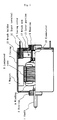
- FIG. 4 shows such a conventional small-sized motor having a metallic casing cover, wherein the overall structure of the motor is shown on the leftmost side with the upper half of the motor shown in cross section; an end bell formed of a synthetic resin and removed from the casing is shown on the right side thereof; and a casing cover is shown on the rightmost side.
- Magnets 1 are attached to the inner surface of a casing 2, which is formed of a metallic material and into a closed-bottomed cylindrical shape.
- a casing cover 5 is fitted to the casing 2 so as to close an opening portion of the casing 2.
- a bearing 6 for a shaft 7 is mounted at a central portion of the casing cover 5. The other end of the shaft 7 is supported by a bearing 3, which is disposed at the center of a bottom portion of the casing 2 having a closed-bottomed cylindrical shape.
- the shaft 7 is equipped with a laminated core 8, windings 9 wound around the laminated core 8, and a commutator 10, thereby forming a rotor of the small-sized motor. Brushes in contact with the commutator 10 are supported by the end bell 4. Input terminals 11 connected to the brushes extend through the casing cover 5 and are projected to the outside for electrical connection.
- the metallic casing cover 5 is located outermost, and the end bell 4 ⁇ which is formed of a synthetic resin and supports the brushes, the input terminals 11, and the like ⁇ is disposed on the inner side of the casing cover 5 and is fitted into the opening portion of the casing 2. Since the bearing 6 is accommodated in the center portion of the metallic casing cover 5, stable bearing alignment is secured. However, when an electrical element is to be attached to the outer surface of the metallic casing cover 5, it becomes necessary to provide a cover formed of synthetic resin, paper, or the like for insulting the electrical element from the casing cover 5.
- the casing cover 5 may be formed from a synthetic resin through injection molding in which the casing cover 5 is molded integrally with the end bell to thereby secure insulation.
- the accuracy of the casing cover 5 becomes inferior to that of a metallic casing cover produced through cutting work. Therefore, the accuracy in alignment of bearings disposed on the opposite sides of the motor deteriorates, so that the clearance between the shaft and each of the bearings must be increased.
- the shaft hits the bearings due to electromagnetic force of the motor and other causes, resulting in generation of clearance noise.
- a spherical bearing may be employed as a self-aligning mechanism. In this case, since a part for supporting the bearing becomes necessary, cost increases.
- An object of the present invention is to provide a small-sized motor which maintains the advantageous feature of a metallic casing cover to thereby secure stable bearing alignment and which provides insulation outside the motor to thereby enable attachment of an electrical element to the motor without use of any additional insulation means.
- a small-sized motor of the present invention comprises a metallic casing 2 having a closed-bottomed cylindrical shape and including a magnet 1 attached to an inner surface thereof; a casing cover 5 fitted to the casing 2 so as to close an opening portion of the casing 2; and a rotor including a shaft 7, a laminated core 8 mounted on the shaft 7, windings 9 wound around the laminated core 8, and a commutator 10 mounted on the shaft 7.
- the motor further comprises an insulation holder 16 which is integrally molded from a synthetic resin.
- the insulation holder 16 comprises a cover portion 13 for covering the casing cover 5 from the outer side thereof, and a pair of brush holders 12 which project from the cover portion 13 into the interior of the motor, while passing through cut portions formed in the casing cover 5.
- Each of the brush holder 12 supports a brush arm 17 and an input terminal 11 connected thereto.
- the brush arm 17 supports a carbon brush 18.
- Bearings 3 and 6 for the shaft are respectively supported at the center of the bottom portion of the casing 2 and at the center of the casing cover 5. Thus, stable bearing alignment is realized, and an insulating property can be imparted to the outer surface of the motor.
- a pair of magnet pressers 14 can be formed integrally with the insulation holder 16 such that the magnet pressers 14 project into the interior of the motor via the cut portions formed in the casing cover 5, to thereby axially position the magnet 1.
- FIG. 1 is a longitudinal sectional view of a small-sized motor of the present invention, sectionally showing the upper half of the motor.
- the small-sized motor of the present invention is the same as that of the conventional small-sized motor described with reference to FIG. 4 except the structures of the casing cover and the insulation holder integrally fitted thereto.
- magnets 1 are attached to the inner surface of a casing 2, which is formed of a metallic material and into a closed-bottomed cylindrical shape.
- a metallic casing cover 5 is fitted to the casing 2 so as to close an opening portion of the casing 2.
- a bearing 6 for a shaft 7 is mounted at a central portion of the casing cover 5. Since the casing cover 5 is formed of metal, the casing cover 5 can be produced accurately through press work or cutting work, so that stable bearing alignment can be realized.
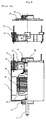
- FIG. 2 shows the casing cover and the insulation holder of the small-sized motor shown in FIG. 1, wherein a cross-sectional view is shown on the right side, and a view as viewed from the interior of the motor toward the casing cover is shown on the left side.
- FIG. 3 is a schematic exploded view of the casing cover and the insulation holder, in which details of the structure are omitted in order to clarify the mutual relationship between the casing cover and the insulation holder.
- the metallic casing cover 5 generally has a circular shape suitable for attachment to the opening portion of the casing 2.
- the metallic casing cover 5 has cut portions into which the upper and lower brush holders 12 and right and left magnet pressers 14 are fitted, a center hole for receiving a shaft bearing, and a plurality of ventilation openings 15 for cooling purpose.
- the insulation holder 16 formed of synthetic resin and integrally fitted to the metallic casing cover 5 has a cover portion 13, the upper and lower brush holders 12, and the right and left magnet pressers 14, which are integrally formed from synthetic resin.
- the cover portion 13 generally has a circular shape corresponding to the shape of the casing cover 5.
- the cover portion 13 is constructed to cover the casing cover 5 from the outer side thereof and has openings and holes formed at positions corresponding to those of the ventilation openings 15 and the bearing receiving hole of the metallic casing cover.
- the pair of brush holders 12 project into the interior of the motor via the cut portions at the outer circumferential portion of the casing cover 5 and support the brush arms 17 and the input terminals 11 connected thereto.
- the motor according to the present invention comprises the insulation holder 16 which is integrally formed from synthetic resin and which includes a cover portion 13 for covering the casing cover 5 from the outside thereof, and the pair of brush holders 12 which project from the cover portion 13 into the interior of the motor via the cut portions provided in the casing cover 5. Therefore, it becomes possible to maintain an advantageous feature of the metallic casing cover to thereby secure stable bearing alignment and to provide insulation outside the motor to thereby enable attachment of an electrical element to the motor without use of any additional insulation means.
Landscapes
- Engineering & Computer Science (AREA)
- Power Engineering (AREA)
- Motor Or Generator Frames (AREA)
- Motor Or Generator Current Collectors (AREA)
Applications Claiming Priority (2)
| Application Number | Priority Date | Filing Date | Title |
|---|---|---|---|
| JP02121399A JP3345365B2 (ja) | 1999-01-29 | 1999-01-29 | 小型モータ |
| JP2121399 | 1999-01-29 |
Publications (3)
| Publication Number | Publication Date |
|---|---|
| EP1024582A2 true EP1024582A2 (de) | 2000-08-02 |
| EP1024582A3 EP1024582A3 (de) | 2003-03-05 |
| EP1024582B1 EP1024582B1 (de) | 2005-11-16 |
Family
ID=12048732
Family Applications (1)
| Application Number | Title | Priority Date | Filing Date |
|---|---|---|---|
| EP00101472A Expired - Lifetime EP1024582B1 (de) | 1999-01-29 | 2000-01-26 | Kleinmotor |
Country Status (5)
| Country | Link |
|---|---|
| US (1) | US6294850B1 (de) |
| EP (1) | EP1024582B1 (de) |
| JP (1) | JP3345365B2 (de) |
| CN (1) | CN1197222C (de) |
| DE (1) | DE60023962T2 (de) |
Cited By (3)
| Publication number | Priority date | Publication date | Assignee | Title |
|---|---|---|---|---|
| WO2004040736A1 (fr) * | 2002-10-25 | 2004-05-13 | Valeo Equipements Electriques Moteur | Capot de protection destiné à être monté sur le palier arrière d'une machine électrique tournante, alternateur et alterno-démarreur comportant un tel capot |
| US7722444B2 (en) | 2005-05-13 | 2010-05-25 | Black & Decker Inc. | Angle grinder |
| US10818450B2 (en) | 2017-06-14 | 2020-10-27 | Black & Decker Inc. | Paddle switch |
Families Citing this family (13)
| Publication number | Priority date | Publication date | Assignee | Title |
|---|---|---|---|---|
| KR100278006B1 (ko) * | 1998-11-11 | 2001-01-15 | 윤종용 | 정류자를 구비한 전자렌지, 및 전자렌지용 정류자의 제조방법 |
| CA2398199A1 (en) * | 2000-01-28 | 2001-08-02 | Asahi Kasei Kabushiki Kaisha | Novel therapeutic agents that use a .beta.3 agonist |
| JP3699644B2 (ja) * | 2000-02-10 | 2005-09-28 | アスモ株式会社 | 給電端子内蔵モータ |
| DE10051403A1 (de) * | 2000-10-17 | 2002-06-13 | Minebea Co Ltd | Rotorbaugruppe für einen Elektromotor und Innenläufer-Elektromotor |
| JP3503822B2 (ja) | 2001-01-16 | 2004-03-08 | ミネベア株式会社 | 軸流ファンモータおよび冷却装置 |
| US8141231B2 (en) * | 2003-09-15 | 2012-03-27 | Shop Vac | Electric motor |
| US7135795B2 (en) * | 2003-12-02 | 2006-11-14 | Franklin Electric Co., Inc. | Insert molded end bell for a submersible motor and method of manufacture thereof |
| JP4861305B2 (ja) | 2007-12-28 | 2012-01-25 | マブチモーター株式会社 | 有ブラシdcモータのケース蓋組立体 |
| JP2013138545A (ja) * | 2011-12-28 | 2013-07-11 | Nisca Corp | モータ |
| US10348158B2 (en) * | 2015-02-04 | 2019-07-09 | Makita Corporation | Power tool |
| CN106329790B (zh) * | 2015-06-16 | 2018-12-25 | 佛山市建准电子有限公司 | 马达 |
| FR3080233B1 (fr) * | 2018-04-17 | 2021-04-16 | Valeo Equip Electr Moteur | Ensemble comprenant une machine electrique tournante et un tendeur de courroie |
| JP7576065B2 (ja) | 2022-08-26 | 2024-10-30 | マブチモーター株式会社 | モータ |
Family Cites Families (23)
| Publication number | Priority date | Publication date | Assignee | Title |
|---|---|---|---|---|
| GB1317424A (en) * | 1971-01-07 | 1973-05-16 | Ward Goldstone Ltd | Electric motor |
| US3654504A (en) * | 1971-03-29 | 1972-04-04 | Gen Electric | Brush mechanism |
| US3735172A (en) * | 1971-12-22 | 1973-05-22 | Gen Signal Corp | Motor brush holder |
| US3745393A (en) * | 1972-04-28 | 1973-07-10 | Briggs & Stratton Corp | Brush holder for dynamoelectric machine |
| JPS5657661U (de) * | 1979-10-11 | 1981-05-18 | ||
| GB2152295B (en) * | 1983-12-14 | 1986-12-31 | Mabuchi Motor Co | Cover plate |
| JPS6088886A (ja) * | 1983-10-21 | 1985-05-18 | Hitachi Ltd | 燃料供給ポンプ |
| JPS60162957U (ja) * | 1984-04-09 | 1985-10-29 | マブチモ−タ−株式会社 | 小型モ−タ |
| GB2160370B (en) * | 1984-04-27 | 1987-11-11 | Mabuchi Motor Co | Electric motor |
| GB2181305B (en) * | 1985-10-04 | 1989-09-13 | Johnson Electric Ind Mfg | Electric motors |
| JPS62178762U (de) * | 1986-05-01 | 1987-11-13 | ||
| GB2207291A (en) * | 1987-06-23 | 1989-01-25 | Johnson Electric Ind Mfg | A housing for an electric motor and a method of making same |
| DE8717075U1 (de) * | 1987-12-30 | 1988-03-24 | Kress-elektrik GmbH & Co, Elektromotorenfabrik, 7457 Bisingen | Elektrischer Universalmotor |
| US4965478A (en) * | 1988-09-02 | 1990-10-23 | Mitsuba Electric Mfg. Co., Ltd. | DC motor with a durable pigtail arrangement |
| JPH0649086Y2 (ja) * | 1989-01-21 | 1994-12-12 | マブチモーター株式会社 | 周波数発電機をそなえた小型モータ |
| US5089735A (en) * | 1989-12-11 | 1992-02-18 | Sawafuji Electric Co., Ltd. | Direct-current motor |
| JPH03230738A (ja) * | 1990-02-06 | 1991-10-14 | Mitsubishi Electric Corp | 電動機 |
| JPH04124857U (ja) * | 1991-04-23 | 1992-11-13 | マブチモーター株式会社 | 小型モータ |
| US5387832A (en) * | 1991-04-25 | 1995-02-07 | Tokyo Electric Co., Ltd. | Brush and commutator motor having brush device using the same |
| JP2708694B2 (ja) * | 1993-05-31 | 1998-02-04 | マブチモーター株式会社 | 小型モータ |
| DE69422790T2 (de) * | 1993-12-22 | 2000-09-07 | Denso Corp., Kariya | Rotierende elektrische Maschine mit Kommutator |
| GB9826912D0 (en) * | 1998-12-09 | 1999-01-27 | Johnson Electric Sa | Miniature electric motor |
| JP3394921B2 (ja) * | 1999-01-29 | 2003-04-07 | マブチモーター株式会社 | 小型モータ |
-
1999
- 1999-01-29 JP JP02121399A patent/JP3345365B2/ja not_active Expired - Fee Related
-
2000
- 2000-01-26 EP EP00101472A patent/EP1024582B1/de not_active Expired - Lifetime
- 2000-01-26 US US09/491,776 patent/US6294850B1/en not_active Expired - Fee Related
- 2000-01-26 DE DE60023962T patent/DE60023962T2/de not_active Expired - Fee Related
- 2000-01-28 CN CNB001019155A patent/CN1197222C/zh not_active Expired - Lifetime
Cited By (8)
| Publication number | Priority date | Publication date | Assignee | Title |
|---|---|---|---|---|
| WO2004040736A1 (fr) * | 2002-10-25 | 2004-05-13 | Valeo Equipements Electriques Moteur | Capot de protection destiné à être monté sur le palier arrière d'une machine électrique tournante, alternateur et alterno-démarreur comportant un tel capot |
| FR2849548A1 (fr) * | 2002-10-25 | 2004-07-02 | Valeo Equip Electr Moteur | Capot de protection destine a etre monte sur le palier arriere d'une machine electrique tournante, alternateur et alterno-demarreur comportant un tel capot |
| CN100456603C (zh) * | 2002-10-25 | 2009-01-28 | 瓦莱奥电机设备公司 | 旋转电机保护罩及有该保护罩的交流发电机和交流起动机 |
| US7554232B2 (en) | 2002-10-25 | 2009-06-30 | Valeo Equipments Electriques Moteur | Protective cover which is intended to be mounted on the rear bearing of a rotating electrical machine, alternator and alternator-starter comprising one such cover |
| US7722444B2 (en) | 2005-05-13 | 2010-05-25 | Black & Decker Inc. | Angle grinder |
| US8087976B2 (en) | 2005-05-13 | 2012-01-03 | Black & Decker Inc. | Trigger assembly for angle grinder |
| US8087977B2 (en) | 2005-05-13 | 2012-01-03 | Black & Decker Inc. | Angle grinder |
| US10818450B2 (en) | 2017-06-14 | 2020-10-27 | Black & Decker Inc. | Paddle switch |
Also Published As
| Publication number | Publication date |
|---|---|
| US6294850B1 (en) | 2001-09-25 |
| JP3345365B2 (ja) | 2002-11-18 |
| EP1024582B1 (de) | 2005-11-16 |
| CN1197222C (zh) | 2005-04-13 |
| CN1271202A (zh) | 2000-10-25 |
| EP1024582A3 (de) | 2003-03-05 |
| DE60023962D1 (de) | 2005-12-22 |
| HK1030838A1 (zh) | 2001-05-18 |
| JP2000224795A (ja) | 2000-08-11 |
| DE60023962T2 (de) | 2006-06-01 |
Similar Documents
| Publication | Publication Date | Title |
|---|---|---|
| US6294850B1 (en) | Small-sized motor | |
| US6166468A (en) | Rotary electric machine and bearing structure thereof | |
| JP3639211B2 (ja) | モータ | |
| US11056953B2 (en) | Stator unit, motor, and fan motor | |
| CN109478820B (zh) | 电机 | |
| US20010006598A1 (en) | Blower | |
| US6603235B1 (en) | Small-sized motor having a brush unit with an improved brush arm and terminal connections | |
| US6023113A (en) | Axial flow fan motor | |
| JP4463395B2 (ja) | コンデンサ電動機およびその製造方法 | |
| KR101655112B1 (ko) | 브러쉬리스 dc 모터 | |
| US6954012B2 (en) | Permanent electric motor with a speed sensor | |
| CN112564369A (zh) | 马达及送风装置 | |
| JP7081160B2 (ja) | モータ | |
| US12368342B2 (en) | Motor | |
| JPH08140311A (ja) | モータ冷却軸受構造 | |
| CN111384811A (zh) | 马达 | |
| JP5195118B2 (ja) | 電動機 | |
| JP2896059B2 (ja) | アウターロータ型ブラシレスdcモータ | |
| JP3015644B2 (ja) | アウターロータ型ブラシレスdcモータ | |
| JP2004208400A (ja) | アウターロータ型モータ | |
| JP4372959B2 (ja) | モータ | |
| CN216564730U (zh) | 电动机、送风装置及抽油烟机 | |
| US6617741B2 (en) | Commutator for electric rotary machine and manufacturing method thereof | |
| JP2001128409A (ja) | リード線付き小型モータ | |
| JP2002010604A (ja) | 電動機 |
Legal Events
| Date | Code | Title | Description |
|---|---|---|---|
| PUAI | Public reference made under article 153(3) epc to a published international application that has entered the european phase |
Free format text: ORIGINAL CODE: 0009012 |
|
| AK | Designated contracting states |
Kind code of ref document: A2 Designated state(s): AT BE CH CY DE DK ES FI FR GB GR IE IT LI LU MC NL PT SE |
|
| AX | Request for extension of the european patent |
Free format text: AL;LT;LV;MK;RO;SI |
|
| PUAL | Search report despatched |
Free format text: ORIGINAL CODE: 0009013 |
|
| AK | Designated contracting states |
Designated state(s): AT BE CH CY DE DK ES FI FR GB GR IE IT LI LU MC NL PT SE Kind code of ref document: A3 Designated state(s): AT BE CH CY DE DK ES FI FR GB GR IE IT LI LU MC NL PT SE |
|
| AX | Request for extension of the european patent |
Extension state: AL LT LV MK RO SI |
|
| RIC1 | Information provided on ipc code assigned before grant |
Ipc: 7H 02K 13/00 B Ipc: 7H 02K 5/15 B Ipc: 7H 02K 5/167 B Ipc: 7H 02K 5/04 A Ipc: 7H 01R 39/38 B Ipc: 7H 02K 5/02 B Ipc: 7H 02K 9/22 B Ipc: 7H 02K 5/14 B |
|
| 17P | Request for examination filed |
Effective date: 20030409 |
|
| 17Q | First examination report despatched |
Effective date: 20030519 |
|
| AKX | Designation fees paid |
Designated state(s): DE FR GB IT |
|
| GRAP | Despatch of communication of intention to grant a patent |
Free format text: ORIGINAL CODE: EPIDOSNIGR1 |
|
| RIN1 | Information on inventor provided before grant (corrected) |
Inventor name: FURUYA, KENJII Inventor name: YUI, TOSHIYA |
|
| RTI1 | Title (correction) |
Free format text: SMALL-SIZED MOTOR |
|
| RAP1 | Party data changed (applicant data changed or rights of an application transferred) |
Owner name: MABUCHI MOTOR CO., LTD. |
|
| GRAS | Grant fee paid |
Free format text: ORIGINAL CODE: EPIDOSNIGR3 |
|
| GRAA | (expected) grant |
Free format text: ORIGINAL CODE: 0009210 |
|
| AK | Designated contracting states |
Kind code of ref document: B1 Designated state(s): DE FR GB IT |
|
| REG | Reference to a national code |
Ref country code: GB Ref legal event code: FG4D |
|
| REF | Corresponds to: |
Ref document number: 60023962 Country of ref document: DE Date of ref document: 20051222 Kind code of ref document: P |
|
| ET | Fr: translation filed | ||
| PLBE | No opposition filed within time limit |
Free format text: ORIGINAL CODE: 0009261 |
|
| STAA | Information on the status of an ep patent application or granted ep patent |
Free format text: STATUS: NO OPPOSITION FILED WITHIN TIME LIMIT |
|
| 26N | No opposition filed |
Effective date: 20060817 |
|
| PGFP | Annual fee paid to national office [announced via postgrant information from national office to epo] |
Ref country code: DE Payment date: 20090123 Year of fee payment: 10 |
|
| PGFP | Annual fee paid to national office [announced via postgrant information from national office to epo] |
Ref country code: GB Payment date: 20090121 Year of fee payment: 10 |
|
| PGFP | Annual fee paid to national office [announced via postgrant information from national office to epo] |
Ref country code: IT Payment date: 20090129 Year of fee payment: 10 |
|
| PGFP | Annual fee paid to national office [announced via postgrant information from national office to epo] |
Ref country code: FR Payment date: 20090113 Year of fee payment: 10 |
|
| GBPC | Gb: european patent ceased through non-payment of renewal fee |
Effective date: 20100126 |
|
| REG | Reference to a national code |
Ref country code: FR Ref legal event code: ST Effective date: 20100930 |
|
| PG25 | Lapsed in a contracting state [announced via postgrant information from national office to epo] |
Ref country code: FR Free format text: LAPSE BECAUSE OF NON-PAYMENT OF DUE FEES Effective date: 20100201 |
|
| PG25 | Lapsed in a contracting state [announced via postgrant information from national office to epo] |
Ref country code: DE Free format text: LAPSE BECAUSE OF NON-PAYMENT OF DUE FEES Effective date: 20100803 |
|
| PG25 | Lapsed in a contracting state [announced via postgrant information from national office to epo] |
Ref country code: GB Free format text: LAPSE BECAUSE OF NON-PAYMENT OF DUE FEES Effective date: 20100126 |
|
| PG25 | Lapsed in a contracting state [announced via postgrant information from national office to epo] |
Ref country code: IT Free format text: LAPSE BECAUSE OF NON-PAYMENT OF DUE FEES Effective date: 20100126 |