EP1024343B1 - Rotierendes Laserbeleuchtungssystem - Google Patents
Rotierendes Laserbeleuchtungssystem Download PDFInfo
- Publication number
- EP1024343B1 EP1024343B1 EP00300628A EP00300628A EP1024343B1 EP 1024343 B1 EP1024343 B1 EP 1024343B1 EP 00300628 A EP00300628 A EP 00300628A EP 00300628 A EP00300628 A EP 00300628A EP 1024343 B1 EP1024343 B1 EP 1024343B1
- Authority
- EP
- European Patent Office
- Prior art keywords
- laser beam
- unit
- range
- finding
- rotator
- Prior art date
- Legal status (The legal status is an assumption and is not a legal conclusion. Google has not performed a legal analysis and makes no representation as to the accuracy of the status listed.)
- Expired - Lifetime
Links
- 230000001678 irradiating effect Effects 0.000 title claims description 61
- 230000003287 optical effect Effects 0.000 claims description 37
- 230000010287 polarization Effects 0.000 claims description 36
- 238000001514 detection method Methods 0.000 description 10
- 238000004891 communication Methods 0.000 description 7
- 238000000034 method Methods 0.000 description 7
- 239000013307 optical fiber Substances 0.000 description 4
- 230000010355 oscillation Effects 0.000 description 4
- 230000005540 biological transmission Effects 0.000 description 2
- 238000004364 calculation method Methods 0.000 description 2
- 230000008859 change Effects 0.000 description 2
- 238000010586 diagram Methods 0.000 description 2
- 230000004907 flux Effects 0.000 description 2
- 230000006872 improvement Effects 0.000 description 2
- 238000005259 measurement Methods 0.000 description 2
- 238000000638 solvent extraction Methods 0.000 description 2
- 230000001154 acute effect Effects 0.000 description 1
- 230000015572 biosynthetic process Effects 0.000 description 1
- 238000009434 installation Methods 0.000 description 1
- 230000007246 mechanism Effects 0.000 description 1
- 238000003909 pattern recognition Methods 0.000 description 1
- 230000008569 process Effects 0.000 description 1
- 230000004044 response Effects 0.000 description 1
Images


Classifications
-
- G—PHYSICS
- G02—OPTICS
- G02B—OPTICAL ELEMENTS, SYSTEMS OR APPARATUS
- G02B26/00—Optical devices or arrangements for the control of light using movable or deformable optical elements
- G02B26/08—Optical devices or arrangements for the control of light using movable or deformable optical elements for controlling the direction of light
- G02B26/0816—Optical devices or arrangements for the control of light using movable or deformable optical elements for controlling the direction of light by means of one or more reflecting elements
-
- G—PHYSICS
- G01—MEASURING; TESTING
- G01C—MEASURING DISTANCES, LEVELS OR BEARINGS; SURVEYING; NAVIGATION; GYROSCOPIC INSTRUMENTS; PHOTOGRAMMETRY OR VIDEOGRAMMETRY
- G01C15/00—Surveying instruments or accessories not provided for in groups G01C1/00 - G01C13/00
- G01C15/002—Active optical surveying means
- G01C15/004—Reference lines, planes or sectors
Definitions
- the scanning means 15 irradiates the laser beam 80 along rotating direction by reciprocal scanning.
- the following means may be used, for example: a galvanometer for changing an advancing direction of incident laser beam by vibrating a mirror, a rotary polygon mirror scanner for scanning reflection light by rotating a polygon mirror, a hologram disk scanner for scanning laser beam by rotating a disk where a plurality of holograms, having varied direction of diffraction gratings and varied pitch in relation to space, is formed, or an acousto-optical element, etc.
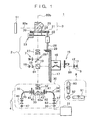
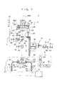
- the range-finding unit 4 comprises a range-finding optical system 30 and a range-finding arithmetic unit 31. First, the range-finding optical system 30 is described.
- the range-finding photodetection unit 35 comprises a band-pass filter 43 and a density filter 44 on the side opposite to the optical path switching slit 41 with the aperture prism 33 at the middle. After passing through the band-pass filter 43 and the density filter 44, the range-finding laser beam enters a range-finding photodetection element 47 via an optical fiber 45 and a condenser lens 46.
- the light is emitted from the first laser diode 11 via the driver 54, and the light is deflected in a horizontal direction by the pentagonal prism 25 and it is projected.
- the scanning motor 22 is driven by the motor driver 53.
- the scanning means 15 is operated by the scan driver 56.
- the pentagonal prism 25 is rotated via the driving gear 21 and the scanning gear 20 while scanning is performed.
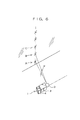
- the laser beam 80a is projected by rotary irradiation, and a horizontal reference plane is formed.
- the scanning means 15 irradiates the laser beam 80 by reciprocal scanning in a direction in parallel to paper surface, i.e. in the scanning direction of the laser beam 80a by the pentagonal prism 25.
- the projected image is rotated by two turns while the image rotator 16 is rotated by one turn, and the image rotator 16 is rotated by 1/2 turn while the pentagonal prism 25 is rotated by one turn.
- the laser beam is irradiated from the pentagonal prism 25, a scanning direction of the laser beam by the scanning means 15 is not rotated, and reciprocal scanning is performed always in a scanning direction.
- the LED 36 is driven by the range-finding arithmetic unit 31 and the emitted range-finding light 82 is projected toward the object reflector 51, and range-finding or distance measurement is performed.
- the range-finding light 82 is reflected by the object reflector 51 and the light enters the photodetection unit 35 via the pentagonal prism 25 and the beam splitter 10.
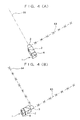
- the rotary laser irradiating system 1 is rotated at an angle of 90° within the horizontal plane.
- the laser beam 80a is aligned with the reference line 83, and marking along the reference line 84 can be carried out by repeating the same procedure as the marking operation as described above. (See Fig. 4 (B).)
- a method to detect a plurality of reflection surfaces of the object reflector 51 is described in JP-A-6-137870, for example.
- the photodetection unit can receive the laser beam reflected from the three reflection sectors, and the laser beam can be directed toward the central position of the object reflector 51 based on three pulses obtained and on the output of the encoder 23.
- reset To change the distance from the position A to the distance from the position C, reset must be performed for once.
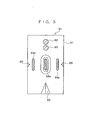
- Reset signal can be sent as described below by a light beam emitted from a light emitting element 62 provided on the object reflector 51 toward the rotary laser irradiating system 1.
- a projection optical system 6 On the optical axis of the reflection light from the beam splitter 10, a projection optical system 6 is arranged. Further, a photodetection unit 7 is disposed with respect to the projection optical system 6.
- the laser beam 80a emitted from the first laser diode 11 is converted to a circularly polarized light by the ⁇ /4 birefringence member 13. After passing through the anamorphic prism 14, its luminous flux cross-section is turned to circular shape. After passing through the scanning means 15 and the image rotator 16, it is reflected by the beam splitter 10 and is deflected at an angle of 90° by the pentagonal prism 25 and is irradiated.
- the focusing optical system 27 focuses the laser beam 80a irradiated from the pentagonal prism 25 on the object reflector 51 based on the range-finding data from the range-finding unit 4 or projects the light toward infinity.
- the irradiating direction of the laser beam when the laser beam 80a is irradiated to the reflection sectors 68 can be detected based on the time of outputs of the photodetection signal from the first photodetection element 88 and the second photodetection element 90 and also based on the result of angle detection from the encoder 23 and the detection result of the deflection detecting means 48. Based on the detection result, it is possible to accurately project the range-finding light toward the band-pass filter 72.
- the main unit 2 comprises the range-finding light emitting unit 34, the range-finding photodetection unit 35, and the range-finding arithmetic unit 31 and also because the object reflector 51 comprises the light emitting element 62, the photodetection element 63, and the control base plate 64, mutual communication by modulated light can be achieved between the main unit 2 and the object reflector 51.
- the control base plate 64 drives the light emitting element 62 (e.g. LED), and the light beam modulated to a predetermined modulation frequency is emitted from the light emitting element 62.
- An oscillation wavelength of the light emitted from the light emitting element 62 is set to a value closer or equal to that of the laser beam 80a.
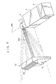
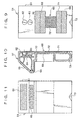
- each of the ⁇ /4 birefringence member 70 and the ⁇ /4 birefringence member 71 is changed, each of which covers an upper flange-like portion and a lower flange-like portion of an I-shape reflection plates 69.
- Each of the upper flange-like portion and the lower flange-like portion is divided into two triangular sections by diagonal line respectively, and the ⁇ /4 birefringence member 70 and the ⁇ /4 birefringence member 71 are attached on the upper triangular section. In the remaining triangular section in the lower portion, the reflection plate 69 is exposed.
- photodetection signals from the photodetection unit 7 can be varied.
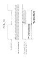
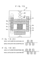
- the reflection pattern 76 shown in Fig. 15 three polarization converting sectors 74 each in the same shape and two polarization maintaining sectors 75 are arranged alternately.
- the photodetection signal from the photodetection unit 7 is turned to the one as shown in Fig. 16(A).
- the reflection pattern 77 three polarization converting sectors 74 and three polarization maintaining sectors 75 are arranged alternately.
- the photodetection signal from the photodetection unit 7 is turned to the one as shown in Fig. 16 (B).
Landscapes
- Physics & Mathematics (AREA)
- General Physics & Mathematics (AREA)
- Engineering & Computer Science (AREA)
- Radar, Positioning & Navigation (AREA)
- Remote Sensing (AREA)
- Optics & Photonics (AREA)
- Optical Radar Systems And Details Thereof (AREA)
- Measurement Of Optical Distance (AREA)
- Length Measuring Devices By Optical Means (AREA)
Claims (8)
- Rotierendes Laserbeleuchtungssystem (1), welches eine Laserlichtquelle (5), eine Entfernungsmesseinheit (4), eine Drehvorrichtung (3) zum Aussenden eines Laserstrahls aus der Laserlichtquelle (5) und ein Entfernungsmesslicht von der Entfernungsmesseinheit (4) auf eine Referenzebene durch rotierendes Ausstrahlen umfasst, sowie eine Scanneinrichtung (15), die sich auf einem optischen Pfad (80) zwischen der Laserlichtquelle (5) und der Drehvorrichtung (3) befindet und derart konstruiert und angeordnet ist, dass sie den Laserstrahl ablenkt, sowie eine Bilddrehvorrichtung (16), die auf einem optischen Pfad (80) zwischen der Scanneinrichtung (15) und der Drehvorrichtung (3) angeordnet ist, wobei die Bilddrehvorrichtung (16) so konstruiert und angeordnet ist, dass sie den Laserstrahl von der Scanneinrichtung (15) dreht, wobei die Bilddrehvorrichtung (16) derart verriegelt ist, dass die Bilddrehvorrichtung (16) um eine halbe Umdrehung gedreht wird, wenn die Drehvorrichtung (3) um eine ganze Umdrehung gedreht wird.
- Rotierendes Laserbeleuchtungssystem nach Anspruch 1, wobei das System ferner eine Steuereinheit (9), ein Verschlüsselungsgerät (23) zum Erkennen einer Ausstrahlrichtung der Drehvorrichtung (3) und eine Photodetektionseinheit (7) zum Empfangen eines Laserstrahls der von einem Objektreflektor (51) reflektiert wird, der auf der Referenzebene angeordnet ist, wobei die Photodetektionseinheit (7) und das Verschlüsselungsgerät (23) Ausgänge aufweisen, wobei basierend auf den Ausgängen die Steuereinheit zum Steuern der Drehung der Drehvorrichtung (3) angeordnet ist.
- Rotierendes Laserbeleuchtungssystem nach Anspruch 2, wobei das System so angepasst ist, dass es das Entfernungsmesslicht und den Laserstrahl auf den Objektreflektor (51) richtet.
- Rotierendes Laserbeleuchtungssystem nach einem der vorhergehenden Ansprüche, wobei der Laserstrahl aus der Laserlichtquelle sichtbares Licht ist, und das Entfernungsmesslicht aus der Entfernungsmesseinheit nicht sichtbares Licht ist.
- Rotierendes Laserbeleuchtungssystem nach einem der vorhergehenden Ansprüche, wobei ein optisches Fokussierungssystem (27) auf einem optischen Pfad zwischen der Bilddrehvorrichtung (16) und der Drehvorrichtung (3) vorgesehen ist, wobei das optische System (27) so konstruiert und angeordnet ist, dass es den Laserstrahl (80) auf die Position des Objektreflektors (51) fokussiert, und zwar basierend auf einer Distanz, welche durch die Entfernungsmesseinheit (4) gemessen wird.
- Rotierendes Laserbeleuchtungssystem nach einem der vorhergehenden Ansprüche, wobei der von der Lichtemissionseinheit ausgesendete Laserstrahl ein polarisierter Laserstrahl ist, wobei der Objektreflektor ein Reflexionsmuster aufweist, welches eine Oberfläche zum Reflektieren des polarisierten Laserstrahls hat, während er eine Polarisierungsrichtung beibehält, sowie eine Oberfläche zum Reflektieren des polarisierten Laserstrahls, während er eine Polarisierungsrichtung umwandelt, wobei die Photodetektionseinheit eine erste Erkennungseinheit und eine zweite Erkennungseinheit zum Empfangen von Lichtstrahlen mit unterschiedlichen Polarisierungsrichtungen aufweist, und wobei die Steuereinheit (9) so angeordnet ist, dass sie das Muster basierend auf Ausgängen erkennt, welche durch die erste und zweite Erkennungseinheit erkannt werden, wodurch der Betrieb gesteuert wird.
- Rotierendes Laserbeleuchtungssystem nach Anspruch 1, wobei die Drehvorrichtung (3) ein Verschlüsselungsgerät (23) zum Erkennen einer Aussendungsrichtung der Drehvorrichtung (3) umfasst, wobei die Entfernungsmesseinheit (4) so ausgestaltet ist, dass sie eine erste und eine zweite Position eines Objektreflektors misst, und das Verschlüsselungsgerät (23) so ausgestaltet ist, dass es einen Drehwinkel von der ersten Position zu der zweiten Position erkennt.
- Rotierendes Laserbeleuchtungssystem nach Anspruch 7, wobei der Objektreflektor eine Anzeigeeinheit (58) aufweist, welche so konstruiert und angeordnet ist, dass sie die Distanz von der ersten Position zu der zweiten Position anzeigt.
Applications Claiming Priority (2)
| Application Number | Priority Date | Filing Date | Title |
|---|---|---|---|
| JP02201499A JP4180718B2 (ja) | 1999-01-29 | 1999-01-29 | 回転レーザ装置 |
| JP2201499 | 1999-01-29 |
Publications (3)
| Publication Number | Publication Date |
|---|---|
| EP1024343A2 EP1024343A2 (de) | 2000-08-02 |
| EP1024343A3 EP1024343A3 (de) | 2000-10-18 |
| EP1024343B1 true EP1024343B1 (de) | 2005-11-09 |
Family
ID=12071156
Family Applications (1)
| Application Number | Title | Priority Date | Filing Date |
|---|---|---|---|
| EP00300628A Expired - Lifetime EP1024343B1 (de) | 1999-01-29 | 2000-01-27 | Rotierendes Laserbeleuchtungssystem |
Country Status (4)
| Country | Link |
|---|---|
| US (1) | US6483106B1 (de) |
| EP (1) | EP1024343B1 (de) |
| JP (1) | JP4180718B2 (de) |
| DE (1) | DE60023762T2 (de) |
Families Citing this family (59)
| Publication number | Priority date | Publication date | Assignee | Title |
|---|---|---|---|---|
| GB2362070B (en) * | 2000-05-05 | 2004-06-16 | Nokia Mobile Phones Ltd | Communication devices and method of communication |
| JP4407179B2 (ja) * | 2003-07-09 | 2010-02-03 | ソニー株式会社 | レーザディスプレイ装置 |
| AU2003246995A1 (en) | 2003-07-22 | 2005-02-04 | Nokia Corporation | Reader device for radio frequency identification transponder with transponder functionality |
| JP4290520B2 (ja) * | 2003-10-14 | 2009-07-08 | 株式会社トプコン | レーザ照射装置 |
| ITMI20032565A1 (it) * | 2003-12-22 | 2005-06-23 | Calzoni Srl | Dispositivo ottico indicatore dell'angolo di planata per velivoli |
| ES2290667T3 (es) * | 2004-01-23 | 2008-02-16 | Nokia Corporation | Metodo, dispositivo y sistema para informacion de contexto automatizada a partir de datos selectivos proporcionados por medios de identificacion. |
| WO2005093643A1 (en) | 2004-03-17 | 2005-10-06 | Nokia Corporation | Continuous data provision by radio frequency identification (rfid) transponders |
| DE602004020684D1 (de) | 2004-03-19 | 2009-05-28 | Nokia Corp | Nd verfahren zur verbesserung des terminal-betriebs |
| JP2006133066A (ja) * | 2004-11-05 | 2006-05-25 | Hara Doki Kk | 巻尺 |
| EP1659417A1 (de) * | 2004-11-19 | 2006-05-24 | Leica Geosystems AG | Verfahren zur Bestimmung der Ausrichtung eines Ausrichtungsindikators |
| DE102005006726A1 (de) * | 2005-02-03 | 2006-08-10 | Carl Zeiss Optronics Gmbh | Verfahren und Vorrichtung zum Entdecken von optischen Systemen in einem Geländebereich |
| KR100682960B1 (ko) * | 2006-01-20 | 2007-02-15 | 삼성전자주식회사 | 레이저 직선자 및 이를 이용한 거리 측정 및 라인 투사방법 |
| DE202006005643U1 (de) * | 2006-03-31 | 2006-07-06 | Faro Technologies Inc., Lake Mary | Vorrichtung zum dreidimensionalen Erfassen eines Raumbereichs |
| US20080000968A1 (en) * | 2006-06-30 | 2008-01-03 | Robert Thomas Cato | Rotating Light Beam/Distance Meter Based Location Determining System |
| US7511804B1 (en) * | 2007-04-10 | 2009-03-31 | Itt Manufacturing Enterprises, Inc. | Crossed beam roof target for motion tracking |
| EP2053353A1 (de) | 2007-10-26 | 2009-04-29 | Leica Geosystems AG | Distanzmessendes Verfahren und ebensolches Gerät |
| JP5376707B2 (ja) * | 2008-01-24 | 2013-12-25 | 株式会社半導体エネルギー研究所 | レーザアニール装置 |
| JP2009209566A (ja) * | 2008-03-04 | 2009-09-17 | Ym Kogyo Kk | 可動手すり |
| CN101526346A (zh) * | 2008-03-05 | 2009-09-09 | 鸿富锦精密工业(深圳)有限公司 | 便携式电子装置及其测量物体长度的方法 |
| JP5234254B2 (ja) * | 2008-05-08 | 2013-07-10 | 株式会社Ihi | レーザレーダ及びレーザレーダの較正方法 |
| JP5234255B2 (ja) * | 2008-05-13 | 2013-07-10 | 株式会社Ihi | レーザレーダ及びレーザレーダの据付方向調整方法 |
| CN102301199B (zh) * | 2008-12-05 | 2013-09-18 | 麦克罗尼克迈达塔有限责任公司 | 用于旋转系统的笛卡尔坐标测量 |
| DE102009010465B3 (de) * | 2009-02-13 | 2010-05-27 | Faro Technologies, Inc., Lake Mary | Laserscanner |
| US9551575B2 (en) | 2009-03-25 | 2017-01-24 | Faro Technologies, Inc. | Laser scanner having a multi-color light source and real-time color receiver |
| DE102009015920B4 (de) | 2009-03-25 | 2014-11-20 | Faro Technologies, Inc. | Vorrichtung zum optischen Abtasten und Vermessen einer Umgebung |
| EP2280580A1 (de) * | 2009-07-07 | 2011-02-02 | Nokia Corporation | Datenübertragung mit drahtlos betriebenen Kommunikationsvorrichtungen |
| DE102009035337A1 (de) | 2009-07-22 | 2011-01-27 | Faro Technologies, Inc., Lake Mary | Verfahren zum optischen Abtasten und Vermessen eines Objekts |
| DE102009038964A1 (de) * | 2009-08-20 | 2011-02-24 | Faro Technologies, Inc., Lake Mary | Verfahren zum optischen Abtasten und Vermessen einer Umgebung |
| DE102009057101A1 (de) | 2009-11-20 | 2011-05-26 | Faro Technologies, Inc., Lake Mary | Vorrichtung zum optischen Abtasten und Vermessen einer Umgebung |
| US9210288B2 (en) | 2009-11-20 | 2015-12-08 | Faro Technologies, Inc. | Three-dimensional scanner with dichroic beam splitters to capture a variety of signals |
| DE102009055989B4 (de) | 2009-11-20 | 2017-02-16 | Faro Technologies, Inc. | Vorrichtung zum optischen Abtasten und Vermessen einer Umgebung |
| DE102009055988B3 (de) | 2009-11-20 | 2011-03-17 | Faro Technologies, Inc., Lake Mary | Vorrichtung zum optischen Abtasten und Vermessen einer Umgebung |
| US9113023B2 (en) | 2009-11-20 | 2015-08-18 | Faro Technologies, Inc. | Three-dimensional scanner with spectroscopic energy detector |
| US9529083B2 (en) | 2009-11-20 | 2016-12-27 | Faro Technologies, Inc. | Three-dimensional scanner with enhanced spectroscopic energy detector |
| US9163922B2 (en) | 2010-01-20 | 2015-10-20 | Faro Technologies, Inc. | Coordinate measurement machine with distance meter and camera to determine dimensions within camera images |
| US9628775B2 (en) | 2010-01-20 | 2017-04-18 | Faro Technologies, Inc. | Articulated arm coordinate measurement machine having a 2D camera and method of obtaining 3D representations |
| US9879976B2 (en) | 2010-01-20 | 2018-01-30 | Faro Technologies, Inc. | Articulated arm coordinate measurement machine that uses a 2D camera to determine 3D coordinates of smoothly continuous edge features |
| US8028432B2 (en) | 2010-01-20 | 2011-10-04 | Faro Technologies, Inc. | Mounting device for a coordinate measuring machine |
| US9607239B2 (en) | 2010-01-20 | 2017-03-28 | Faro Technologies, Inc. | Articulated arm coordinate measurement machine having a 2D camera and method of obtaining 3D representations |
| DE102010020925B4 (de) | 2010-05-10 | 2014-02-27 | Faro Technologies, Inc. | Verfahren zum optischen Abtasten und Vermessen einer Umgebung |
| DE102010032726B3 (de) | 2010-07-26 | 2011-11-24 | Faro Technologies, Inc. | Vorrichtung zum optischen Abtasten und Vermessen einer Umgebung |
| DE102010032725B4 (de) | 2010-07-26 | 2012-04-26 | Faro Technologies, Inc. | Vorrichtung zum optischen Abtasten und Vermessen einer Umgebung |
| DE102010032723B3 (de) | 2010-07-26 | 2011-11-24 | Faro Technologies, Inc. | Vorrichtung zum optischen Abtasten und Vermessen einer Umgebung |
| DE102010033561B3 (de) | 2010-07-29 | 2011-12-15 | Faro Technologies, Inc. | Vorrichtung zum optischen Abtasten und Vermessen einer Umgebung |
| US9168654B2 (en) | 2010-11-16 | 2015-10-27 | Faro Technologies, Inc. | Coordinate measuring machines with dual layer arm |
| JP6009753B2 (ja) * | 2011-10-26 | 2016-10-19 | 株式会社トプコン | 画像測定装置 |
| DE102012100609A1 (de) | 2012-01-25 | 2013-07-25 | Faro Technologies, Inc. | Vorrichtung zum optischen Abtasten und Vermessen einer Umgebung |
| US8997362B2 (en) | 2012-07-17 | 2015-04-07 | Faro Technologies, Inc. | Portable articulated arm coordinate measuring machine with optical communications bus |
| DE102012107544B3 (de) | 2012-08-17 | 2013-05-23 | Faro Technologies, Inc. | Vorrichtung zum optischen Abtasten und Vermessen einer Umgebung |
| DE102012109481A1 (de) | 2012-10-05 | 2014-04-10 | Faro Technologies, Inc. | Vorrichtung zum optischen Abtasten und Vermessen einer Umgebung |
| US9513107B2 (en) | 2012-10-05 | 2016-12-06 | Faro Technologies, Inc. | Registration calculation between three-dimensional (3D) scans based on two-dimensional (2D) scan data from a 3D scanner |
| US10067231B2 (en) | 2012-10-05 | 2018-09-04 | Faro Technologies, Inc. | Registration calculation of three-dimensional scanner data performed between scans based on measurements by two-dimensional scanner |
| DE102013208642A1 (de) * | 2013-05-10 | 2014-11-13 | Robert Bosch Gmbh | Mobiles Markierungssystem mit einem Rotationslaser |
| DE102015122844A1 (de) | 2015-12-27 | 2017-06-29 | Faro Technologies, Inc. | 3D-Messvorrichtung mit Batteriepack |
| RU2629684C2 (ru) * | 2016-02-12 | 2017-08-31 | Открытое акционерное общество "Научно-исследовательский институт "Полюс" им. М.Ф. Стельмаха" | Лазерный измеритель дальности с оптическим сумматором |
| CN107144848A (zh) * | 2017-03-31 | 2017-09-08 | 成都理想境界科技有限公司 | 一种定位基站和定位系统 |
| DE102017210683B4 (de) * | 2017-06-26 | 2022-10-20 | Robert Bosch Gmbh | Optische Anordnung einer Empfängeroptik eines abtastenden Lidar-Systems, Lidar-System sowie Arbeitsvorrichtung |
| KR102065640B1 (ko) * | 2017-12-05 | 2020-01-13 | 광주과학기술원 | 라이다 장치 |
| CN109683344B (zh) * | 2019-01-24 | 2023-10-03 | 中国科学院西安光学精密机械研究所 | 用于x射线聚焦镜垂直装调系统的光源装置及其搭建方法 |
Family Cites Families (15)
| Publication number | Priority date | Publication date | Assignee | Title |
|---|---|---|---|---|
| WO1989012836A1 (fr) * | 1988-06-15 | 1989-12-28 | Japan Industrial Land Development Co., Ltd. | Un dispositif de releve du type a poursuite automatique |
| DE69119500T2 (de) * | 1990-07-18 | 1996-11-14 | Spectra Physics Laserplane Inc | System und Verfahren zur dreidimensionalen Positionserfassung |
| JPH05272968A (ja) * | 1992-03-26 | 1993-10-22 | Topcon Corp | レーザー測量機 |
| JP3144710B2 (ja) * | 1992-07-20 | 2001-03-12 | 富士写真光機株式会社 | 位置計測作図装置 |
| JP3100478B2 (ja) * | 1992-10-27 | 2000-10-16 | 株式会社トプコン | 往復レーザ走査システムを有するレーザ回転照射装置 |
| JPH06223397A (ja) * | 1993-01-22 | 1994-08-12 | Asahi Optical Co Ltd | 光記録再生装置 |
| JP3268608B2 (ja) * | 1993-02-12 | 2002-03-25 | 株式会社トプコン | 測量装置 |
| JP3483303B2 (ja) * | 1994-06-21 | 2004-01-06 | 株式会社トプコン | 回転レーザ装置 |
| JP3512469B2 (ja) * | 1994-06-21 | 2004-03-29 | 株式会社トプコン | 測量用装置 |
| JPH08145674A (ja) * | 1994-11-15 | 1996-06-07 | Asahi Optical Co Ltd | レーザ測量装置 |
| JP3681198B2 (ja) * | 1995-05-25 | 2005-08-10 | 株式会社トプコン | レーザ測量機 |
| JP3908297B2 (ja) * | 1996-03-19 | 2007-04-25 | 株式会社トプコン | レーザ測量機 |
| JP3706203B2 (ja) * | 1996-07-22 | 2005-10-12 | 株式会社トプコン | 回転レーザ装置 |
| JPH10293030A (ja) * | 1997-04-18 | 1998-11-04 | Sokkia Co Ltd | 水平面設定機 |
| JPH1114358A (ja) * | 1997-06-18 | 1999-01-22 | Nikon Corp | レーザ測量機 |
-
1999
- 1999-01-29 JP JP02201499A patent/JP4180718B2/ja not_active Expired - Fee Related
-
2000
- 2000-01-05 US US09/477,657 patent/US6483106B1/en not_active Expired - Lifetime
- 2000-01-27 DE DE60023762T patent/DE60023762T2/de not_active Expired - Fee Related
- 2000-01-27 EP EP00300628A patent/EP1024343B1/de not_active Expired - Lifetime
Also Published As
| Publication number | Publication date |
|---|---|
| EP1024343A2 (de) | 2000-08-02 |
| DE60023762T2 (de) | 2006-08-10 |
| EP1024343A3 (de) | 2000-10-18 |
| US6483106B1 (en) | 2002-11-19 |
| DE60023762D1 (de) | 2005-12-15 |
| JP2000221033A (ja) | 2000-08-11 |
| JP4180718B2 (ja) | 2008-11-12 |
Similar Documents
| Publication | Publication Date | Title |
|---|---|---|
| EP1024343B1 (de) | Rotierendes Laserbeleuchtungssystem | |
| US6493067B1 (en) | Rotary laser irradiating system | |
| JP3816807B2 (ja) | 位置測定装置及びそれに使用する回転レーザ装置 | |
| US5907907A (en) | Laser leveling system | |
| US5894123A (en) | Laser rotary irradiating system for irradiating a laser beam | |
| EP2103902B1 (de) | Vermessungsvorrichtung und Vermessungssystem | |
| US5629756A (en) | Laser beam projection apparatus | |
| EP1030163B1 (de) | Reflektierende Prismenvorrichtung | |
| EP0631110A1 (de) | Objektreflektordetektionsvorrichtung | |
| JP4796834B2 (ja) | 距離測定方法及び距離測定装置 | |
| JPH09250927A (ja) | 測量システム | |
| US7554650B2 (en) | Laser beam projecting device | |
| JP4212944B2 (ja) | 測量機 | |
| EP0935152B1 (de) | Laser-Nivelliersystem | |
| JP6749192B2 (ja) | スキャナ装置および測量装置 | |
| JP3681198B2 (ja) | レーザ測量機 | |
| US5774211A (en) | Laser leveling system for setting pipes | |
| JPH11257960A (ja) | レーザー照射装置 | |
| JP3582853B2 (ja) | 対象反射体検出装置 | |
| WO2024232359A1 (ja) | 測量装置及び測量システム | |
| JP3500683B2 (ja) | 鉛直面レーザ投光装置 | |
| JPH07218260A (ja) | レーザ測量装置 | |
| JPH07218618A (ja) | レーザレーダ光軸調整装置 |
Legal Events
| Date | Code | Title | Description |
|---|---|---|---|
| PUAI | Public reference made under article 153(3) epc to a published international application that has entered the european phase |
Free format text: ORIGINAL CODE: 0009012 |
|
| AK | Designated contracting states |
Kind code of ref document: A2 Designated state(s): CH DE LI SE |
|
| AX | Request for extension of the european patent |
Free format text: AL;LT;LV;MK;RO;SI |
|
| PUAL | Search report despatched |
Free format text: ORIGINAL CODE: 0009013 |
|
| AK | Designated contracting states |
Kind code of ref document: A3 Designated state(s): AT BE CH CY DE DK ES FI FR GB GR IE IT LI LU MC NL PT SE |
|
| AX | Request for extension of the european patent |
Free format text: AL;LT;LV;MK;RO;SI |
|
| 17P | Request for examination filed |
Effective date: 20010305 |
|
| AKX | Designation fees paid |
Free format text: CH DE LI SE |
|
| 17Q | First examination report despatched |
Effective date: 20020930 |
|
| GRAP | Despatch of communication of intention to grant a patent |
Free format text: ORIGINAL CODE: EPIDOSNIGR1 |
|
| GRAS | Grant fee paid |
Free format text: ORIGINAL CODE: EPIDOSNIGR3 |
|
| GRAA | (expected) grant |
Free format text: ORIGINAL CODE: 0009210 |
|
| AK | Designated contracting states |
Kind code of ref document: B1 Designated state(s): CH DE LI SE |
|
| REG | Reference to a national code |
Ref country code: CH Ref legal event code: EP |
|
| REF | Corresponds to: |
Ref document number: 60023762 Country of ref document: DE Date of ref document: 20051215 Kind code of ref document: P |
|
| REG | Reference to a national code |
Ref country code: SE Ref legal event code: TRGR |
|
| REG | Reference to a national code |
Ref country code: CH Ref legal event code: NV Representative=s name: KIRKER & CIE SA |
|
| PLBE | No opposition filed within time limit |
Free format text: ORIGINAL CODE: 0009261 |
|
| STAA | Information on the status of an ep patent application or granted ep patent |
Free format text: STATUS: NO OPPOSITION FILED WITHIN TIME LIMIT |
|
| 26N | No opposition filed |
Effective date: 20060810 |
|
| PGFP | Annual fee paid to national office [announced via postgrant information from national office to epo] |
Ref country code: DE Payment date: 20090123 Year of fee payment: 10 |
|
| PGFP | Annual fee paid to national office [announced via postgrant information from national office to epo] |
Ref country code: CH Payment date: 20090126 Year of fee payment: 10 |
|
| PGFP | Annual fee paid to national office [announced via postgrant information from national office to epo] |
Ref country code: SE Payment date: 20090108 Year of fee payment: 10 |
|
| REG | Reference to a national code |
Ref country code: CH Ref legal event code: PL |
|
| EUG | Se: european patent has lapsed | ||
| PG25 | Lapsed in a contracting state [announced via postgrant information from national office to epo] |
Ref country code: LI Free format text: LAPSE BECAUSE OF NON-PAYMENT OF DUE FEES Effective date: 20100131 Ref country code: CH Free format text: LAPSE BECAUSE OF NON-PAYMENT OF DUE FEES Effective date: 20100131 |
|
| PG25 | Lapsed in a contracting state [announced via postgrant information from national office to epo] |
Ref country code: DE Free format text: LAPSE BECAUSE OF NON-PAYMENT OF DUE FEES Effective date: 20100803 |
|
| PG25 | Lapsed in a contracting state [announced via postgrant information from national office to epo] |
Ref country code: SE Free format text: LAPSE BECAUSE OF NON-PAYMENT OF DUE FEES Effective date: 20100128 |