EP1024343B1 - Rotary laser irradiating system - Google Patents
Rotary laser irradiating system Download PDFInfo
- Publication number
- EP1024343B1 EP1024343B1 EP00300628A EP00300628A EP1024343B1 EP 1024343 B1 EP1024343 B1 EP 1024343B1 EP 00300628 A EP00300628 A EP 00300628A EP 00300628 A EP00300628 A EP 00300628A EP 1024343 B1 EP1024343 B1 EP 1024343B1
- Authority
- EP
- European Patent Office
- Prior art keywords
- laser beam
- unit
- range
- finding
- rotator
- Prior art date
- Legal status (The legal status is an assumption and is not a legal conclusion. Google has not performed a legal analysis and makes no representation as to the accuracy of the status listed.)
- Expired - Lifetime
Links
- 230000001678 irradiating effect Effects 0.000 title claims description 61
- 230000003287 optical effect Effects 0.000 claims description 37
- 230000010287 polarization Effects 0.000 claims description 36
- 238000001514 detection method Methods 0.000 description 10
- 238000004891 communication Methods 0.000 description 7
- 238000000034 method Methods 0.000 description 7
- 239000013307 optical fiber Substances 0.000 description 4
- 230000010355 oscillation Effects 0.000 description 4
- 230000005540 biological transmission Effects 0.000 description 2
- 238000004364 calculation method Methods 0.000 description 2
- 230000008859 change Effects 0.000 description 2
- 238000010586 diagram Methods 0.000 description 2
- 230000004907 flux Effects 0.000 description 2
- 230000006872 improvement Effects 0.000 description 2
- 238000005259 measurement Methods 0.000 description 2
- 238000000638 solvent extraction Methods 0.000 description 2
- 230000001154 acute effect Effects 0.000 description 1
- 230000015572 biosynthetic process Effects 0.000 description 1
- 238000009434 installation Methods 0.000 description 1
- 230000007246 mechanism Effects 0.000 description 1
- 238000003909 pattern recognition Methods 0.000 description 1
- 230000008569 process Effects 0.000 description 1
- 230000004044 response Effects 0.000 description 1
Images


Classifications
-
- G—PHYSICS
- G02—OPTICS
- G02B—OPTICAL ELEMENTS, SYSTEMS OR APPARATUS
- G02B26/00—Optical devices or arrangements for the control of light using movable or deformable optical elements
- G02B26/08—Optical devices or arrangements for the control of light using movable or deformable optical elements for controlling the direction of light
- G02B26/0816—Optical devices or arrangements for the control of light using movable or deformable optical elements for controlling the direction of light by means of one or more reflecting elements
-
- G—PHYSICS
- G01—MEASURING; TESTING
- G01C—MEASURING DISTANCES, LEVELS OR BEARINGS; SURVEYING; NAVIGATION; GYROSCOPIC INSTRUMENTS; PHOTOGRAMMETRY OR VIDEOGRAMMETRY
- G01C15/00—Surveying instruments or accessories not provided for in groups G01C1/00 - G01C13/00
- G01C15/002—Active optical surveying means
- G01C15/004—Reference lines, planes or sectors
Definitions
- the scanning means 15 irradiates the laser beam 80 along rotating direction by reciprocal scanning.
- the following means may be used, for example: a galvanometer for changing an advancing direction of incident laser beam by vibrating a mirror, a rotary polygon mirror scanner for scanning reflection light by rotating a polygon mirror, a hologram disk scanner for scanning laser beam by rotating a disk where a plurality of holograms, having varied direction of diffraction gratings and varied pitch in relation to space, is formed, or an acousto-optical element, etc.
- the range-finding unit 4 comprises a range-finding optical system 30 and a range-finding arithmetic unit 31. First, the range-finding optical system 30 is described.
- the range-finding photodetection unit 35 comprises a band-pass filter 43 and a density filter 44 on the side opposite to the optical path switching slit 41 with the aperture prism 33 at the middle. After passing through the band-pass filter 43 and the density filter 44, the range-finding laser beam enters a range-finding photodetection element 47 via an optical fiber 45 and a condenser lens 46.
- the light is emitted from the first laser diode 11 via the driver 54, and the light is deflected in a horizontal direction by the pentagonal prism 25 and it is projected.
- the scanning motor 22 is driven by the motor driver 53.
- the scanning means 15 is operated by the scan driver 56.
- the pentagonal prism 25 is rotated via the driving gear 21 and the scanning gear 20 while scanning is performed.
- the laser beam 80a is projected by rotary irradiation, and a horizontal reference plane is formed.
- the scanning means 15 irradiates the laser beam 80 by reciprocal scanning in a direction in parallel to paper surface, i.e. in the scanning direction of the laser beam 80a by the pentagonal prism 25.
- the projected image is rotated by two turns while the image rotator 16 is rotated by one turn, and the image rotator 16 is rotated by 1/2 turn while the pentagonal prism 25 is rotated by one turn.
- the laser beam is irradiated from the pentagonal prism 25, a scanning direction of the laser beam by the scanning means 15 is not rotated, and reciprocal scanning is performed always in a scanning direction.
- the LED 36 is driven by the range-finding arithmetic unit 31 and the emitted range-finding light 82 is projected toward the object reflector 51, and range-finding or distance measurement is performed.
- the range-finding light 82 is reflected by the object reflector 51 and the light enters the photodetection unit 35 via the pentagonal prism 25 and the beam splitter 10.
- the rotary laser irradiating system 1 is rotated at an angle of 90° within the horizontal plane.
- the laser beam 80a is aligned with the reference line 83, and marking along the reference line 84 can be carried out by repeating the same procedure as the marking operation as described above. (See Fig. 4 (B).)
- a method to detect a plurality of reflection surfaces of the object reflector 51 is described in JP-A-6-137870, for example.
- the photodetection unit can receive the laser beam reflected from the three reflection sectors, and the laser beam can be directed toward the central position of the object reflector 51 based on three pulses obtained and on the output of the encoder 23.
- reset To change the distance from the position A to the distance from the position C, reset must be performed for once.
- Reset signal can be sent as described below by a light beam emitted from a light emitting element 62 provided on the object reflector 51 toward the rotary laser irradiating system 1.
- a projection optical system 6 On the optical axis of the reflection light from the beam splitter 10, a projection optical system 6 is arranged. Further, a photodetection unit 7 is disposed with respect to the projection optical system 6.
- the laser beam 80a emitted from the first laser diode 11 is converted to a circularly polarized light by the ⁇ /4 birefringence member 13. After passing through the anamorphic prism 14, its luminous flux cross-section is turned to circular shape. After passing through the scanning means 15 and the image rotator 16, it is reflected by the beam splitter 10 and is deflected at an angle of 90° by the pentagonal prism 25 and is irradiated.
- the focusing optical system 27 focuses the laser beam 80a irradiated from the pentagonal prism 25 on the object reflector 51 based on the range-finding data from the range-finding unit 4 or projects the light toward infinity.
- the irradiating direction of the laser beam when the laser beam 80a is irradiated to the reflection sectors 68 can be detected based on the time of outputs of the photodetection signal from the first photodetection element 88 and the second photodetection element 90 and also based on the result of angle detection from the encoder 23 and the detection result of the deflection detecting means 48. Based on the detection result, it is possible to accurately project the range-finding light toward the band-pass filter 72.
- the main unit 2 comprises the range-finding light emitting unit 34, the range-finding photodetection unit 35, and the range-finding arithmetic unit 31 and also because the object reflector 51 comprises the light emitting element 62, the photodetection element 63, and the control base plate 64, mutual communication by modulated light can be achieved between the main unit 2 and the object reflector 51.
- the control base plate 64 drives the light emitting element 62 (e.g. LED), and the light beam modulated to a predetermined modulation frequency is emitted from the light emitting element 62.
- An oscillation wavelength of the light emitted from the light emitting element 62 is set to a value closer or equal to that of the laser beam 80a.
- each of the ⁇ /4 birefringence member 70 and the ⁇ /4 birefringence member 71 is changed, each of which covers an upper flange-like portion and a lower flange-like portion of an I-shape reflection plates 69.
- Each of the upper flange-like portion and the lower flange-like portion is divided into two triangular sections by diagonal line respectively, and the ⁇ /4 birefringence member 70 and the ⁇ /4 birefringence member 71 are attached on the upper triangular section. In the remaining triangular section in the lower portion, the reflection plate 69 is exposed.
- photodetection signals from the photodetection unit 7 can be varied.
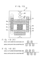
- the reflection pattern 76 shown in Fig. 15 three polarization converting sectors 74 each in the same shape and two polarization maintaining sectors 75 are arranged alternately.
- the photodetection signal from the photodetection unit 7 is turned to the one as shown in Fig. 16(A).
- the reflection pattern 77 three polarization converting sectors 74 and three polarization maintaining sectors 75 are arranged alternately.
- the photodetection signal from the photodetection unit 7 is turned to the one as shown in Fig. 16 (B).
Landscapes
- Physics & Mathematics (AREA)
- General Physics & Mathematics (AREA)
- Optics & Photonics (AREA)
- Engineering & Computer Science (AREA)
- Radar, Positioning & Navigation (AREA)
- Remote Sensing (AREA)
- Optical Radar Systems And Details Thereof (AREA)
- Measurement Of Optical Distance (AREA)
- Length Measuring Devices By Optical Means (AREA)
Description
- The present invention relates to a rotary laser irradiating system for forming a reference plane used for such cases as room interior finishing work, partitioning work, etc., and in particular, to a rotary laser irradiating system equipped with a range-finder. Further, the invention relates to an object reflector used in association with the rotary laser irradiating system.
- As one of the processes in room interior finishing work, partitioning work, etc, marking operation should be performed. In conventional type marking operation, a horizontal reference plane, a vertical reference plane, and a tilt reference plane or a horizontal reference line, a vertical reference line and a tilt reference line are formed by a rotary laser irradiating system. Based on the horizontal reference plane, the vertical reference plane and the tilt reference plane or a horizontal reference line, a vertical reference line and a tilt reference line, working points are projected on floor surface or wall surface at predetermined dimensions.
- When marking is performed at a predetermined point on a certain reference line, a separate range-finding device has been used in the past to measure the distance, or position of the working point has been determined using a device such as a tape measure.
- Also, a conventional type rotary laser irradiating system capable to form a laser reference plane is disclosed in JP-A-6-137870.
- The conventional type rotary laser irradiating system, as described in JP-A-6-137870 comprises a main unit of the rotary laser irradiating system for forming a laser reference plane by irradiating laser beam and an object reflector arranged at a predetermined position and for reflecting laser beam toward the main unit of the system. The object reflector has two reflection surfaces arranged with a predetermined distance from each other, and the main unit of the system is provided with a photodetection unit, which receives the laser beam reflected from the object reflector. When the photodetection unit receives the laser beam from two reflection surfaces and two pulses are detected, a rotating direction of the laser irradiation is reversed. By repeating this reversing procedure, reciprocal operation is performed on the object reflector, and this improves visibility of the laser beam.
- In the marking operation using the conventional type rotary laser irradiating system as described above, a reference line is formed on wall surface or the like by the laser beam irradiated by rotary irradiation. The predetermined working points on the reference line had to be determined manually by an operator using a range-finding device, a tape measure, etc. For this reason, complicated procedure has been required for marking operation. In a type of rotary laser irradiating system for performing reciprocal operation on the object reflector to improve visibility of laser beam, a distance had to be similarly measured to determine the working points, and this means that much complicated procedure was required for the marking operation.
- Another prior art system is disclosed in EP-A-875728. This document discloses a surveying system which comprises a light source section for emitting a laser beam, a rotational portion for rotating the laser beam with the light source in the horizontal direction, a light source driving section for driving the light source unit, a survey instrument main unit having a light receiving unit for receiving the reflected laser beam, and a reflecting object for reflecting the laser beam irradiated from the survey instrument main unit towards the main unit of the survey instrument.
- According to the present invention there is provided a rotary laser irradiating system comprising a laser light source, a range-finding unit, a rotator for irradiating a laser beam from said laser light source and a range-finding light from said range-finding unit onto a reference plane by rotary irradiation, and a scanning means disposed on an optical path between said laser light source and said rotator, the scanning means being constructed and arranged to deflect the laser beam, and an image rotator disposed on an optical path between said scanning means and said rotator, said image rotator being constructed and arranged to rotate the laser beam from said scanning means, said image rotator is interlocked in such a manner that said image rotator is rotated by one half turn when said rotator is rotated by one turn.
-
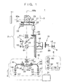
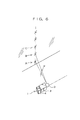
- Fig. 1 is a schematical drawing to show an arrangement of an essential portion of an embodiment of the present invention;
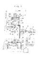
- Fig. 2 is a black diagram showing an essential portion of the embodiment of the present invention;
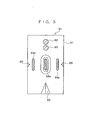
- Fig. 3 is a front view of an object reflector;
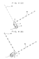
- Fig. 4 (A) and Fig. 4 (B) each represents a drawing to explain an operation of the embodiment of the present invention;
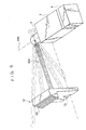
- Fig. 5 is a drawing to explain an operation of the embodiment of the present invention;
- Fig. 6 is a drawing to explain positioning in a vertical direction;
- Fig. 7 is a schematical drawing to show an arrangement of another embodiment of the present invention;
- Fig. 8 is a block diagram of an essential portion of the above embodiment of the present invention;
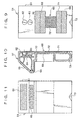
- Fig. 9 is a front view of an object reflector used in the above embodiment of the present invention;
- Fig. 10 is a cross-sectional elevation view of the object reflector;
- Fig. 11 is a rear view of the object reflector;
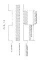
- Fig. 12 is a drawing to show modulation statuses of laser beam and range-finding light and status of a photodetection signal from a photodetection unit;
- Fig. 13 is a drawing to explain an essential portion of a modified example of the object reflector used in the embodiment of the present invention;
- Fig. 14 is a drawing to explain an essential portion of another modified example of the object reflector used in the embodiment of the present invention;
- Fig. 15 is a drawing to explain an essential portion of an application example of the object reflector used in the embodiment of the present invention; and
- Fig. 16 (A) and Fig. 16 (B) each represents a pattern of a photodetection signal from the object reflector.
-
- Detailed description will be given below on embodiments of the present invention referring to the attached drawings.
- Fig. 1 shows an essential portion of a rotary laser irradiating
system 1, which comprises amain unit 2, arotator 3 rotatably mounted on themain unit 2, and a range-finding unit 4 removably mounted on themain unit 2. On themain unit 2, there are provided alight emitting unit 5 for emitting a reference laser beam, aphotodetection unit 7, atilt detecting unit 8, a control unit 9 (to be described later), and a focusingoptical system 27. - First, the reference
light emitting unit 5 will be described. - With a
beam splitter 10 arranged at the middle, afirst laser diode 11 for emitting avisible laser beam 80 is disposed on one side. Acollimator lens 12 for turning the laser beam to parallel beams is disposed on the optical axis of thefirst laser diode 11 and between thefirst laser diode 11 and thebeam splitter 10. Further, ascanning means 15 is arranged on the optical axis of thelaser beam 80 and animage rotator 16 is rotatably disposed. - The scanning means 15 irradiates the
laser beam 80 along rotating direction by reciprocal scanning. As the scanning means, the following means may be used, for example: a galvanometer for changing an advancing direction of incident laser beam by vibrating a mirror, a rotary polygon mirror scanner for scanning reflection light by rotating a polygon mirror, a hologram disk scanner for scanning laser beam by rotating a disk where a plurality of holograms, having varied direction of diffraction gratings and varied pitch in relation to space, is formed, or an acousto-optical element, etc. - For the purpose of associating the deflection of projecting direction by the
rotator 3 with the deflection of projecting direction by the scanning means 15, a deflection detecting means 48 for detecting deflection is arranged on the scanning means 15. As the deflection detecting means 48, an encoder is used in case the scanning means 15 rotates the hologram disk. When an acousto-optical element is used as the scanning means 15, frequency is counted over time and it is associated with the position detected by anencoder 23 of therotator 3, and an actual projecting direction is detected by calculation. - The
image rotator 16 is arranged on a rotation shaft of anaperture bevel gear 17, and theaperture bevel gear 17 is disposed in such manner that it can be rotated around the optical axis of thelaser beam 80. Theimage rotator 16 has such function that a project image is rotated by two turns while theimage rotator 16 is rotated by one turn. - With the
beam splitter 10 at the middle, asecond laser diode 18 for emitting avisible laser beam 81 is arranged on the other side, i.e. on the side opposite to thefirst laser diode 11. On the optical axis of thesecond laser diode 18 and between thesecond laser diode 18 and thebeam splitter 10, acollimator lens 19 is disposed. Thebeam splitter 10 reflects thelaser beams first laser diode 11 and thesecond laser diode 18 respectively and transmits a range-finding light 82 coming from anLED 36, which is to be described later. Thelaser beam 80 from thefirst laser diode 11 is reflected by thebeam splitter 10 and passes through theaperture mirror 26 and is directed toward apentagonal prism 25 via the focusingoptical system 27. Thelaser beam 81 from thesecond laser diode 18 is reflected in a direction opposite to the direction of thelaser beam 80 and it passes through the range-finding unit 4 and is directed in a downward direction. Lens groups of the focusingoptical system 27 are arranged between thebeam splitter 10 and therotator 3. Based on range-finding data from the range-finding unit 4, the focusing opticalsystem driving unit 49 adjusts lens positions and focuses laser beams to the position of an object, for which distance is to be measured. - Now, description will be given on the
rotator 3. - A
prism holder 24 is rotatably supported so that it can be rotated around the optical axis of the laser beam emitted from thebeam splitter 10. Thepentagonal prism 25 is fixed on theprism holder 24, and thepentagonal prism 25 deflects apart 80a of thelaser beam 80 from the referencelight emitting unit 5 at an angle of 90° and it transmits theremainder 80b of thelaser beam 80. Theencoder 23 for detecting rotation of the prism holder 24 (i.e. the pentagonal prism 25) is disposed on theprism holder 24. - The
photodetection unit 7 detects reflection light when thelaser beam 80a projected from thepentagonal prism 25 is reflected by anobject reflector 51 and the reflection light enters the rotary laser irradiatingsystem 1. The light beam irradiated through thepentagonal prism 25 and reflected by theaperture mirror 26 is detected by the photodetection unit. - A
scanning gear 20 is fixed on theprism holder 24, and adriving gear 21 is engaged with thescanning gear 20. Thedriving gear 21 is engaged on a drivingshaft 28 of ascanning motor 22, and it is driven and rotated by thescanning motor 22. Asmall bevel gear 29 is mounted on the drivingshaft 28. Thesmall bevel gear 29 is engaged with theaperture bevel gear 17, and a gear ratio between theaperture bevel gear 17 and thesmall bevel gear 29 is 2:1. When thepentagonal prism 25 is rotated by two turns, theimage rotator 16 is rotated by one turn. - On the
tilt detecting unit 8, anX-axis tilt sensor 91, a Y-axis tilt sensor 92 and a Z-axis tilt sensor 93 are arranged on three perpendicular axes respectively. When the optical axis of the reflection light from thebeam splitter 10 runs in a vertical direction, the X-axis and the Y-axis form a horizontal plane, and the Z-axis and the X-axis form a vertical plane. Themain unit 2 is designed in such structure that it can be arranged at a position where it is rotated at an angle of 90° around an axis, which is parallel to the X-axis (preferably, the X-axis) from the condition shown in Fig. 1. When themain unit 2 is rotated from the condition shown in Fig. 1 to a condition where it is rotated at an angle of 90 ° around the axis in parallel to the X-axis (preferably, the X-axis), the X-axis and the Y-axis form a vertical plane, and the Z-axis and the X-axis form a horizontal plane. - The
X-axis tilt sensor 91 and the Y-axis tilt sensor 92 detect a tilt of the rotarylaser irradiating system 1 at the condition shown in Fig. 1. TheX-axis tilt sensor 91 and the Z-axis tilt sensor 93 detect a tilt of the rotarylaser irradiating system 1 at a condition where it is rotated at an angle of 90 ° from the condition shown in Fig. 1 (i.e. a condition where it is forced down from the vertical position to the horizontal position). - Description will be given now on the range-finding
unit 4. - The range-finding
unit 4 comprises a range-findingoptical system 30 and a range-findingarithmetic unit 31. First, the range-findingoptical system 30 is described. - A
collimator lens 32 and anaperture prism 33 are arranged on the optical axis of the reflection light from thebeam splitter 10 and on the side opposite to the pentagonal prism. With theaperture prism 33 at the middle, a range-findinglight emitting unit 34 is disposed on one side, and a range-findingphotodetection unit 35 is arranged on the other side. In case thelaser beam 81 is not irradiated, there is no need that theaperture prism 33 has an aperture. - The range-finding
light emitting unit 34 has anLED 36 for emitting a range-findinglight 82. The range-finding light 82 from theLED 36 passes through a collimator lens 37 and anoptical fiber 38 and is directed toward theaperture prism 33. The range-findinglight 82 irradiated from theoptical fiber 38 is switched over to a range-findinglight 82 and areference light 82a by an opticalpath switching slit 41. The range-findinglight 82 is reflected by theaperture prism 33 and is turned to parallel beams by thecollimator lens 32. After passing through thebeam splitter 10, the light enters thepentagonal prism 25. The range-findinglight 82 is deflected at an angle of 90° by thepentagonal prism 25 and it is directed toward theobject reflector 51. Similarly to the case of the laser beam, it may be designed in such manner that a part of the range-finding light passes through thepentagonal prism 25. For the range-findinglight 82, light of invisible wavelength is used in order that it is not confused visually with thelaser beam 80. - After being irradiated from the
optical fiber 38 and switched from the range-findinglight 82 by the opticalpath switching slit 41, thereference light 82a passes through acondenser lens 42 and enters theaperture prism 33. It is then deflected at a predetermined angle by theaperture prism 33 and is reflected by internal reflection and passes through to the opposite side. The transmittedreference light 82a then enters the range-findingphotodetection unit 35. - The range-finding
photodetection unit 35 comprises a band-pass filter 43 and adensity filter 44 on the side opposite to the optical path switching slit 41 with theaperture prism 33 at the middle. After passing through the band-pass filter 43 and thedensity filter 44, the range-finding laser beam enters a range-findingphotodetection element 47 via anoptical fiber 45 and acondenser lens 46. - The range-finding
arithmetic unit 31 comprises a driver (not shown) for driving theLED 36, and a distance to theobject reflector 51 is calculated according to a photodetection signal from the range-findingphotodetection element 47. - Now, description will be given on the
control unit 9 referring to Fig. 2. - To the
control unit 9, a signal from theencoder 23 and signals from thetilt detecting unit 8, the range-findingarithmetic unit 31 and thedeflection detecting unit 48 are inputted. Thescanning motor 22 is driven by amotor driver 53 based on a control signal from thecontrol unit 9. The scanning means 15 is driven by ascanning driver 56 based on a control signal from thecontrol unit 9. Thefirst laser diode 11 and thesecond laser diode 18 emit light beams as these are driven bydrivers control unit 9. - An
operation unit 52 and adisplay unit 58 are connected to thecontrol unit 9, and work instructions such as setting of tilt angle of a reference line or starting or stopping operation are inputted from theoperation unit 52. Operation status of the system or information to be sent to theobject reflector 51 are displayed on thedisplay unit 58. The information to theobject reflector 51 is overlapped on the laser beam by either modulating the laser beam or something else. Thecontrol unit 9 may be divided for controlling themain unit 2 of the rotarylaser irradiating system 1 and the range-findingunit 4, and one of the divided units may be used as a main control unit. By dividing it, it is possible to separate the range-findingunit 4. - In the following, description will be given on operation.
- First, description will be given on setting of a horizontal reference plane and measurement of a distance within the horizontal reference plane.
- The rotary
laser irradiating system 1 is installed vertically at a predetermined position. To confirm the installing position, a part of thelaser beam 80 emitted from thefirst laser diode 11 passes through thepentagonal prism 25 and is turned to thelaser beam 80b irradiated in the vertical direction. Further, thelaser beam 81 emitted from thesecond laser diode 18 and directed toward the range-findingunit 4 by thebeam splitter 10 passes through the aperture of theaperture prism 33 and is projected downward in the vertical direction. The position of the rotarylaser irradiating system 1 is determined by thelaser beam 80b and thelaser beam 81. Horizontal positioning of the rotarylaser irradiating system 1 is performed by thetilt detecting unit 8. Leveling is performed in such manner that the tilt detected by theX-axis tilt sensor 91 and the Y-axis tilt sensor 92 is turned to zero, i.e. a horizontal plane is detected. - The light is emitted from the
first laser diode 11 via thedriver 54, and the light is deflected in a horizontal direction by thepentagonal prism 25 and it is projected. Thescanning motor 22 is driven by themotor driver 53. At the same time, the scanning means 15 is operated by thescan driver 56. Thepentagonal prism 25 is rotated via thedriving gear 21 and thescanning gear 20 while scanning is performed. Thelaser beam 80a is projected by rotary irradiation, and a horizontal reference plane is formed. - The scanning means 15 irradiates the
laser beam 80 by reciprocal scanning in a direction in parallel to paper surface, i.e. in the scanning direction of thelaser beam 80a by thepentagonal prism 25. - As described above, the projected image is rotated by two turns while the
image rotator 16 is rotated by one turn, and theimage rotator 16 is rotated by 1/2 turn while thepentagonal prism 25 is rotated by one turn. When the laser beam is irradiated from thepentagonal prism 25, a scanning direction of the laser beam by the scanning means 15 is not rotated, and reciprocal scanning is performed always in a scanning direction. - For marking operation, the
object reflector 51 is used. The position of the laser beam irradiated to theobject reflector 51 is confirmed, and marking is carried out by utilizing theobject reflector 51. - As shown in Fig. 3,
reflection sectors reflection sector 68a arranged at the middle on theobject reflector 51. Theobject reflector 51 is disposed near a predetermined position, and thelaser beam 80a is irradiated to thereflection sectors reflection sectors photodetection unit 7 recognizes theobject reflector 51, and the range-finding light is directed toward the center of theobject reflector 51, i.e. thereflection sector 68a, and rotation of therotator 3 is stopped. In this case, the laser beam is irradiated approximately around the direction of the range-finding light by reciprocal scanning, and marking position is indicated. Marking operation is performed by utilizing anindicator 60. - The
LED 36 is driven by the range-findingarithmetic unit 31 and the emitted range-findinglight 82 is projected toward theobject reflector 51, and range-finding or distance measurement is performed. - The range-finding
light 82 is reflected by theobject reflector 51 and the light enters thephotodetection unit 35 via thepentagonal prism 25 and thebeam splitter 10. - The range-finding
light 82 reflected by theobject reflector 51 and thereference light 82a with its optical path switched over by the optical path switching slit 41 alternately enter the range-findingphotodetection element 47, and the range-findingarithmetic unit 31 calculates the distance to theobject reflector 51 based on two signals from the range-findingphotodetection element 47. The result of the calculation is displayed on thedisplay unit 58. - When the distance to the
object reflector 51 and an irradiating direction of the laser beam are detected, positioning of other points can be carried out one after another using this position as a reference. That is, theobject reflector 51 is moved to the next point, and distance to theobject reflector 51 and an irradiating direction of the laser beam are detected by the same procedure as described above. Angular deviation of the irradiating direction of the laser beam, which occurs as the result of the moving of theobject reflector 51, is detected by theencoder 23. Based on the result of the detection and on the distances to theobject reflectors 51 at the two points, the distance between the object reflectors before and after the moving is calculated by thecontrol unit 9. That is, positioning of theobject reflector 51 is carried out. - As described above, the range-finding
unit 4 can be removed from or attached to themain unit 2. When range-finding is not performed, the range-findingunit 4 is removed, and the rotarylaser irradiating system 1 is used only for forming reference planes and reference lines. - Next, description will be given on a vertical reference plane, a tilt reference line, and formation of the tilt reference line, and marking operation referring to Fig. 4 and Fig. 5.
- The rotary
laser irradiating system 1 is rotated at an angle of 90° around X-axis or around an axis, which runs in parallel to X-axis, and it is turned to a laid-down position. In this laid-down position, the Y-axis tilt sensor 92 takes a vertical position, while the Z-axis tilt sensor 93 takes a horizontal position. Therefore, theX-axis tilt sensor 91 and the Z-axis tilt sensor 93 are positioned within the horizontal plane. Leveling operation is performed by a leveling system of known type (not shown) for the rotarylaser irradiating system 1 so that the tilt detected by these twotilt sensors laser beam 80a deflected by thepentagonal prism 25 and irradiated from therotator 3 by rotary irradiation forms a vertical reference plane. - Further, an angular position of the
pentagonal prism 25 is detected in advance by theencoder 23 so that thelaser beam 80a deflected and irradiated by thepentagonal prism 25 is directed in a horizontal direction. The result of the detection is inputted and set to thecontrol unit 9 by theoperation unit 52. Accordingly, when leveling operation is completed with the rotarylaser irradiating system 1 at the laid-down position, an angle of theirradiated laser beam 80a can be promptly detected by an angle detection signal from theencoder 23. By inputting an irradiation angle of thelaser beam 80a by theoperation unit 52, the irradiation angle of thelaser beam 80a with respect to the horizontal direction can be set by controlling rotation of thescanning motor 22 via themotor driver 53 while thecontrol unit 9 monitors the signal from theencoder 23. - To perform position alignment with the working position determined by marking etc. with the rotary
laser irradiating system 1 at laid-down position, installation to a reference point should be performed at first. The laser beam is irradiated only in a downward and vertical direction, and it is aligned with a reference point. For a plane direction, alignment is performed by the following three laser beams with the reference point as the center: thelaser beam 80b passing through thepentagonal prism 25, thelaser beam 81 passing through theaperture prism 33, and thelaser beam 80a deflected and irradiated by therotator 3. Thelaser beams - As shown in Fig. 4 and Fig. 5, the
object reflector 51 is moved while thelaser beam 80a irradiated by reciprocal scanning is projected to an adequate position (the center of the indicator) of theobject reflector 51. The horizontal distance between theobject reflector 51 and themain unit 2 is measured by the range-findingunit 4. Therefore, based on the result of range-finding, marking is performed at a position where the measured distance reaches the predetermined value (See Fig. 4 (A).) - Next, when marking operation along a
predetermined reference line 83 has been completed and marking is performed along areference line 84 which runs perpendicularly to thereference line 83, the rotarylaser irradiating system 1 is rotated at an angle of 90° within the horizontal plane. Thelaser beam 80a is aligned with thereference line 83, and marking along thereference line 84 can be carried out by repeating the same procedure as the marking operation as described above. (See Fig. 4 (B).) - When the position marked on a floor surface is to be projected on a ceiling surface, the rotary
laser irradiating system 1 is set at the normal position, and an irradiating position of thelaser beam 81 is aligned with the marking position on the floor surface. Then, the position on the floor surface irradiated bylaser beam 80b will be a projection point. - Next, when a tilt reference line is to be formed, leveling is performed at the laid-down position, and positioning of the rotary
laser irradiating system 1 is performed. Then, a desired angle is set by theoperation unit 52. Thescanning motor 22 is rotated at the angle inputted by theoperation unit 52 via themotor driver 53. Thepentagonal prism 25 is rotated at a desired angle via thedriving gear 21 and thescanning gear 20, and the rotation angle is detected by theencoder 23. As a result, an accurate tilt reference line is formed. The tilt angle is determined by the rotation angle of therotator 3. Because therotator 3 can be rotated over the total circumference, any angle from acute angle to obtuse angle can be set. - With the tilt reference line thus established, the scanning means 15 is driven as shown in Fig. 5 to scan the
laser beam 80 by reciprocal scanning. Then, thelaser beam 80a irradiated from thepentagonal prism 25 forms a partial vertical reference plane. - The tilt reference line and the tilt reference plane are used for the setting of gradient of a staircase or gradient of an inclined surface. Further, when distance is measured with the tilt reference line and the tilt reference plane formed as described above, distance can be measured along the gradient thus set. These are used for determining a mounting position in such cases as the case where marking is performed at a position of a pillar for handrail of a staircase, or the case where a handrail is installed on a wall surface facing to an inclined surface.
- Next, description will be given on positioning in a vertical direction with the system in laid-down position referring to Fig. 6.
- As described above, a plurality of
reflection sectors object reflector 51. When the laser beam is irradiated by rotary scanning while reciprocal scanning is performed and thephotodetection unit 7 receives reflection light from the reflection sectors, theobject reflector 51 is recognized and the range-finding light is directed toward the center of theobject reflector 51, and rotation of the rotator is stopped. If it is supposed that the position of theobject reflector 51 at this moment is A, a distance and a direction to the position A are detected. Next, if theobject reflector 51 is moved to the position B, the laser beam is again irradiated from the rotarylaser irradiating system 1 by rotary scanning. Range-finding light is directed toward the center of theobject reflector 51 at the position B, and a distance and a direction are detected. - The
control unit 9 calculates a distance from the position A to the position B based on the rotation angle of theencoder 23 and the distance of the range-finding unit. Similarly, the distance from the position A to the position C is calculated, and the result is displayed on adisplay unit 65 of theobject reflector 51. In this way, positioning in a vertical direction is carried out. - A method to detect a plurality of reflection surfaces of the
object reflector 51 is described in JP-A-6-137870, for example. Specifically, the photodetection unit can receive the laser beam reflected from the three reflection sectors, and the laser beam can be directed toward the central position of theobject reflector 51 based on three pulses obtained and on the output of theencoder 23. To change the distance from the position A to the distance from the position C, reset must be performed for once. Reset signal can be sent as described below by a light beam emitted from alight emitting element 62 provided on theobject reflector 51 toward the rotarylaser irradiating system 1. - In Fig. 5,
reference numeral 65 represents a display unit, which displays information such as photodetection status of theobject reflector 51. As to be described later, based on a communication signal from the rotarylaser irradiating system 1, a position of the laser beam can be displayed with an arrow on thedisplay unit 65. This is advantageous when the laser beam cannot be confirmed visually.Reference numeral 73 represents an indicator to be used for marking operation. - Next, description will be given on a second embodiment of the present invention referring to Fig. 7 and Fig. 8.
- In this second embodiment, the
main unit 2 identifies theobject reflector 51. As a result, when theobject reflector 51 is moved, thelaser beam 80a can follow, and it is possible to perform mutual communication using modulation light between themain unit 2 and theobject reflector 51. In Fig. 7 and Fig. 8, the same components as shown in Fig. 1 or Fig. 2 are referred by the same symbols, and detailed description is not given here. - Between a
collimator lens 12 and a scanning means 15, a λ/4birefringence member 13, and ananamorphic prism 14 are arranged in this order as seen from thecollimator lens 12. The λ/4birefringence member 13 polarizes a linearly polarized laser beam coming from thefirst laser diode 11 to a circularly polarized laser beam, and theanamorphic prism 14 turns luminous flux cross-section of thelaser beam 80 to circular shape. - On the optical axis of the reflection light from the
beam splitter 10, a projectionoptical system 6 is arranged. Further, aphotodetection unit 7 is disposed with respect to the projectionoptical system 6. - The projection
optical system 6 is arranged between thebeam splitter 10 and therotator 3, and it comprises anaperture mirror 26 and a focusingoptical system 27 arranged on the optical axis of the reflection light from thebeam splitter 10. Thelaser beam 80 from the referencelight emitting unit 5 as reflected by thebeam splitter 10 is guided toward therotator 3. Theaperture mirror 26 reflects reflection light from theobject reflector 51 coming from thepentagonal prism 25 toward thephotodetection unit 7. - The
photodetection unit 7 is arranged at a position opposite to theaperture mirror 26, and it comprises a λ/4birefringence member 85, a polarizationlight beam splitter 86, acondenser lens 87 and afirst photodetection element 88, all of which are arranged on the reflection optical axis of theaperture mirror 26, and also a condenser lens 89 and asecond photodetection element 90, both of which are arranged on the reflection optical axis of thepolarization beam splitter 86. When thelaser beam 80a irradiated from thepentagonal prism 25 is reflected by theobject reflector 51 and the reflection light enters the rotarylaser irradiating system 1, thefirst photodetection element 88 and thesecond photodetection element 90 receive the light and detect the reflection light. Photodetection signal from thefirst photodetection element 88 and thesecond photodetection element 90 are inputted to thecontrol unit 9. - Referring to Fig. 9 to Fig. 11, description will be given now on the
object reflector 51 of the present invention. - On the upper portion of opposed surfaces of a
case 61, which is designed in inverted L-shape, alight emitting element 62 and aphotodetection element 63 are disposed. Approximately at the center of the opposed surfaces, areflection sector 68 designed in I-shape is arranged. Thereflection sector 68 comprises areflection plate 69, a λ/4birefringence member 70, a λ/4birefringence member 71, and a band-pass filter 72. The I-shapedreflection plate 69 is attached on thecase 61. Further, the λ/4birefringence member 70 designed in oblong rectangular shape is attached above thereflection plate 69 to cover the upper half of an upper flange-like portion. Also, the λ/4birefringence member 71 of oblong rectangular shape is attached to cover the upper half of a lower flange-like portion. The band-pass filter 72 is attached on a rib-like portion of the I-shapedreflection plate 69. A wavelength band of the band-pass filter 72 allows the range-findinglight 82 to pass, while it does not allow thelaser beam 80a to pass, for example. The λ/4birefringence member 70 and the λ/4birefringence member 71 constitute a polarization converting reflection sector, and a portion of thereflection plate 69 where it is exposed constitutes a polarization maintaining reflection sector. - On the upper end of the
case 61, there is an inclined opposed surface, and thedisplay unit 65 is disposed on this inclined surface. Acontrol base plate 64 is arranged inside thecase 61, and thelight emitting element 62 and thephotodetection element 63 are connected to thecontrol base plate 64. Thedisplay unit 65 and anoperation switch 66 are also connected. Thecontrol base plate 64 drives thelight emitting element 62 to emit light or modulates the light emitted from thelight emitting element 62 in order to transmit information. The modulated light is emitted toward themain unit 2. From a range-finding light 82 (to be described later) received at thephotodetection element 63, information signal synthesized by processing such as modulation is separated and detected. The result of the detection is displayed on thedisplay unit 65. Because thedisplay unit 65 is inclined, the content of the display can be recognized from any of horizontal direction or vertical direction. Theoperation switch 66 is used for adjusting the brightness of the display or for switching-over of the display. - A V-shaped notch is formed at the center of the lower end of the
case 61, and anindicator 73 is arranged. This is used for position alignment, marking-off, etc. for theobject reflector 51. - In the following, description will be given on the operation.
- The rotary
laser irradiating system 1 detects theobject reflector 51, and it can accurately irradiates the range-finding light onto the band-pass filter 72 of theobject reflector 51. In case theobject reflector 51 is to be detected by the rotarylaser irradiating system 1, it can be achieved regardless of whether the scanning means 15 is operated or stopped. - In the operation while scanning is performed, based on the irradiating position of the
rotator 3 when the photodetection signal from thephotodetection unit 7 is obtained and also based on the detecting position of the deflection detecting means 48 provided on the scanning means 15, irradiation of therotator 3 is directed to the band-pass filter 72 of theobject reflector 51. In this case, the laser beam is reciprocally operated, and the range-finding light is directed to the band-pass filter 72, and the distance is measured. When scanning operation is stopped and the object reflector is traversed by searching, a detection signal is obtained. Then, it is rotated by reversal or by one turn, and the rotation of the laser beam is stopped on the band-pass filter 72 of theobject reflector 51. After stopping, scanning operation is performed and the distance is measured. More detailed description will be given below. - The
laser beam 80a emitted from thefirst laser diode 11 is converted to a circularly polarized light by the λ/4birefringence member 13. After passing through theanamorphic prism 14, its luminous flux cross-section is turned to circular shape. After passing through the scanning means 15 and theimage rotator 16, it is reflected by thebeam splitter 10 and is deflected at an angle of 90° by thepentagonal prism 25 and is irradiated. The focusingoptical system 27 focuses thelaser beam 80a irradiated from thepentagonal prism 25 on theobject reflector 51 based on the range-finding data from the range-findingunit 4 or projects the light toward infinity. - The
laser beam 80a passes through the λ/4birefringence member 70 and the λ/4birefringence member 71 of thereflection sectors 68 of theobject reflector 51 and is reflected by thereflection plate 69. Thus, the direction of polarization of thelaser beam 80a is deflected at an angle of 90° after passing through the λ/4 birefringence members twice. In case of thelaser beam 80a reflected by the portions other than the λ/4birefringence member 70 and the λ/4birefringence member 71, the direction of polarization is maintained and the laser beam is reflected. Depending on the reflection plate used, the direction of polarization may be reversed. Further, the band-pass filter 72 allows the light of a predetermined wavelength to pass, while it cuts off or interrupts the light with wavelength other than the predetermined wavelength. As a result, the light having wavelength other than the wavelength transmissible by the band-pass filter 72 is not reflected. Therefore, in case thelaser beam 80a has wavelength higher than the above wavelength range, the laser beam is not reflected by thereflection sectors 68. - After being reflected by the
reflection sectors 68, thelaser beam 80a passes through thepentagonal prism 25 and enters themain unit 2. It further passes through the focusingoptical system 27 and is reflected by theaperture mirror 26 and is received at thephotodetection unit 7. - When the
laser beam 80a passes through the λ/4birefringence member 85, it is converted to a linearly polarized laser beam. After passing through the birefringence member, the direction of polarization of thelaser beam 80a is varied by 90 ° between the case where it passes through the λ/4birefringence member 70 and the λ/4birefringence member 71 and is reflected and the case where it is directly reflected by thereflection plate 69. Thepolarization beam splitter 86 is designed in such manner that it allows to pass the laser beam which has the same direction of polarization as that of the laser beam emitted from thefirst laser diode 11, while it reflects the laser beam which has the direction of polarization deflected by 90° from the direction of polarization of the laser beam emitted from thefirst laser diode 11. Therefore, thelaser beam 80a directly reflected by thereflection plate 69 enters thefirst photodetection element 88, while thelaser beam 80a reflected by the λ/4birefringence member 70 and the λ/4birefringence member 71 is further reflected by thepolarization beam splitter 86 and enters thesecond photodetection element 90. - By comparing the output from the
first photodetection element 88 with the output from thesecond photodetection element 90, it is possible to identify to which part of thereflection sectors 68 thelaser beam 80a is irradiated. Further, if it is supposed that scanning direction of thelaser beam 80a by thepentagonal prism 25 is set in the top-to-bottom direction as seen in Fig. 7, the irradiating direction of the laser beam when thelaser beam 80a is irradiated to thereflection sectors 68 can be detected based on the time of outputs of the photodetection signal from thefirst photodetection element 88 and thesecond photodetection element 90 and also based on the result of angle detection from theencoder 23 and the detection result of thedeflection detecting means 48. Based on the detection result, it is possible to accurately project the range-finding light toward the band-pass filter 72. - The wavelength range of the band-
pass filter 72 is consistent with the wavelength range of the band-pass filter 43. The range-findinglight 82 reflected by the band-pass filter 72 enters thepentagonal prism 25, and after passing through theaperture mirror 26 and thebeam splitter 10, it is reflected by theaperture prism 33. Then, it passes through the band-pass filter 43, thedensity filter 44 and thecondenser lens 46 and enters the range-findingphotodetection element 47. Thereference light 82a also enters the range-findingphotodetection element 47. A photodetection signal for each of the incident light is inputted to the range-findingarithmetic unit 31, and the distance is calculated. Even when reflection light of thelaser beam 80a enters or external disturbance light enters the range-findingoptical system 30, it is cut off or interrupted by the band-pass filter 43. - Because the
main unit 2 comprises the range-findinglight emitting unit 34, the range-findingphotodetection unit 35, and the range-findingarithmetic unit 31 and also because theobject reflector 51 comprises thelight emitting element 62, thephotodetection element 63, and thecontrol base plate 64, mutual communication by modulated light can be achieved between themain unit 2 and theobject reflector 51. - Next, description will be given below on the mutual communication between the
main unit 2 and theobject reflector 51. - By operation of the
operation switch 66 of theobject reflector 51, thecontrol base plate 64 drives the light emitting element 62 (e.g. LED), and the light beam modulated to a predetermined modulation frequency is emitted from thelight emitting element 62. An oscillation wavelength of the light emitted from thelight emitting element 62 is set to a value closer or equal to that of thelaser beam 80a. - The light beam from the
light emitting element 62 traces along the optical axis of thelaser beam 80. It passes through thepentagonal prism 25 and theaperture mirror 26 and is received at thephotodetection unit 7. Because the oscillation wavelength of the light from thelight emitting element 62 is equal to that of thelaser beam 80a, the light does not reach the range-findingphotodetection unit 35 but it reaches thephotodetection unit 7. Therefore, even when thelight emitting element 62 erroneously emits light during range-finding operation, it is possible to prevent erroneous range-finding operation. - During information communication, the
laser beam 80a reflected by theobject reflector 51 and the light from thelight emitting element 62 enter thephotodetection unit 7. In case thelaser beam 80a is continuously emitted, the light beam from thelight emitting element 62 cannot be recognized unless the light amount from thelight emitting element 62 is greater than the light amount of thelaser beam 80a. For this reason, as shown in Fig. 12, it is designed in such manner that, with respect to thefirst laser diode 11, thefirst laser diode 11 for example is oscillated in a light emitting mode modulated at duty 50% and at 100 Hz. With respect to thelight emitting element 62, it is oscillated at modulation frequency greater than the modulation frequency of thefirst laser diode 11, e.g. at modulation frequency of 1 kHz, 2 kHz, ..... If the band-pass filter 72 as described above is attached on the reflection surface, thelaser beam 80a is shielded, and there is no need to change modulation frequency of thelaser beam 80a and the range-finding light. - For the photodetection signal from the
photodetection unit 7, the time of detection of the photodetection signal from thelight emitting element 62 is set to the time when oscillation of thelaser diode 11 is turned off in a photodetection signal detection circuit (not shown) of thecontrol unit 9, and the photodetection signal from thelight emitting element 62 can be separated and identified from thelaser beam 80a. - Next, description will be given on the case where oscillation frequency of the
light emitting element 62 is made equal to that of the range-findinglight 82. - If it is designed in such manner that there is an apparent difference between modulation frequency of the light beam from the
light emitting element 62 and modulation frequency of the range-findinglight 82 and if a safety device is provided so that data transmission is not performed from theobject reflector 51 while transmission of the range-finding data from the rotarylaser irradiating system 1 is not completed, it is possible to receive light beam from thelight emitting element 62 at the range-findingphotodetection unit 35 and to receive data from theobject reflector 51 without erroneous operation. - The data transmitted from the
object reflector 51 to the rotarylaser irradiating system 1 include: instructions such as angle setting of the tilt reference line in a range-finding mode, a rotary scanning mode of thelaser beam 80a, or a stop mode of thelaser beam 80a. Because the instructions can be sent from theobject reflector 51 to the rotarylaser irradiating system 1 side, the operator can perform most of the work on theobject reflector 51 side, and this contributes to the improvement of working efficiency. - In the second embodiment as described above, it is possible to detect the
object reflector 51 by the rotarylaser irradiating system 1, to set the irradiating position of the laser beam with respect to theobject reflector 51 to an adequate position, and to perform mutual communication between the rotarylaser irradiating system 1 and theobject reflector 51. - Referring Fig. 13, description will be given on a modified example of the
reflection sector 68. - In the
reflection sector 68 shown in Fig. 13, the shape of each of the λ/4birefringence member 70 and the λ/4birefringence member 71 is changed, each of which covers an upper flange-like portion and a lower flange-like portion of an I-shape reflection plates 69. Each of the upper flange-like portion and the lower flange-like portion is divided into two triangular sections by diagonal line respectively, and the λ/4birefringence member 70 and the λ/4birefringence member 71 are attached on the upper triangular section. In the remaining triangular section in the lower portion, thereflection plate 69 is exposed. In this modified example again, the sections where the λ/4birefringence member 70 and the λ/4birefringence member 71 are attached respectively constitute a polarization converting reflection sector where a direction of polarization of thelaser beam 80a is deflected by 90° . The section where thereflection plate 69 is exposed constitutes a polarization maintaining reflection sector where a direction of polarization of the reflected laser beam is maintained. - When the
reflection sector 68 is designed as described above, whenever thelaser beam 80a scans on any portion of the upper and the lower flange-like portions of thereflection sector 68 from any direction, reflection light from the λ/4birefringence member 70 and the λ/4birefringence member 71 and reflection light from thereflection plate 69 appear alternately and are adjacent to each other. The reflection light from the λ/4birefringence member 70 and the λ/4birefringence member 71 are detected by thesecond photodetection element 90, and the reflection light from thereflection plate 69 is detected by thefirst photodetection element 88. By comparing pulse widths of photodetection signals between thephotodetection element 88 and thephotodetection element 90, it is possible to identify a scanning position of thelaser beam 80a. Further, from the pulse generating sequence of the photodetection signals of thephotodetection elements laser beam 80a can be detected, and the central position can be detected from the addition of pulse widths of the photodetection signals of thephotodetection elements - Fig. 14 shows an example, in which the
reflection sector 68 is further modified. Each of the upper flange-like portion and the lower flange-like portion is divided into two triangular sections by diagonal line. On the upper triangular section of the upper flange-like portion, thereflection plate 69 and the λ/4birefringence member 70 are attached by overlapping each other. On the lower triangular section of the lower flange-like portion, only thereflection plate 69 is attached. The remaining triangular section of each of the upper flange-like portion and the lower flange-like portion is arranged as a non-reflection sector. - In this variation example, too, when the
laser beam 80a scans the upper flange-like portion and the lower flange-like portion, the photodetecting condition differs between thefirst photodetection element 88 and thesecond photodetection element 90 depending on the scanning position and the scanning direction. Thus, based on the photodetection signals from thefirst photodetection element 88 and thesecond photodetection element 90, a scanning position and a scanning direction of thelaser beam 80a can be detected in the same manner as the example shown in Fig. 11. - Fig. 15 shows an application example of the
object reflector 51. - A
polarization converting sector 74 with the reflection plate and the λ/4 birefringence member overlapped on it and apolarization maintaining sector 75 with only the reflection plate attached on it are arranged on portions other than thereflection sector 68 on opposed surfaces of theobject reflector 51. As a result, a plurality ofreflection patterns 76 andreflection patterns 77 are provided. - By changing combinations of the
polarization converting sectors 74 and thepolarization maintaining sectors 75 in thereflection patterns photodetection unit 7 can be varied. For example, in thereflection pattern 76 shown in Fig. 15, threepolarization converting sectors 74 each in the same shape and twopolarization maintaining sectors 75 are arranged alternately. When thelaser beam 80a is irradiated for scanning or when theobject reflector 51 is moved with respect to thelaser beam 80a, the photodetection signal from thephotodetection unit 7 is turned to the one as shown in Fig. 16(A). In thereflection pattern 77, threepolarization converting sectors 74 and threepolarization maintaining sectors 75 are arranged alternately. In the same manner as described above, when thereflection pattern 77 is moved relatively with respect to thelaser beam 80a, the photodetection signal from thephotodetection unit 7 is turned to the one as shown in Fig. 16 (B). - When the
control unit 9 is provided with the function of pattern recognition and if it is designed in such manner that a predetermined control signal is issued in response to the pattern, it is possible to send instructions to the rotarylaser irradiating system 1 even when theobject reflector 51 is not provided with a specific transmitting function. For example, in the pattern shown in Fig. 16 (A), the rotarylaser irradiating system 1 is set into a rotary scanning mode. In the pattern shown in Fig. 16 (B), the rotarylaser irradiating system 1 is set into a range-finding mode. - For the pattern based on combinations of the
polarization converting sectors 74 and thepolarization maintaining sectors 75, various variations can be conceived. When a non-reflection sector is provided at the boundary between thepolarization converting sector 74 and thepolarization maintaining sector 75, it is possible to arrange apolarization converting sector 74 and apolarization converting sector 74 adjacent to each other or apolarization maintaining sector 75 and apolarization maintaining sector 75 adjacent to each other. As a result, the more diversified patterns can be provided. Therefore, it is possible to increase the types of instructions to be sent from theobject reflector 51 to the rotarylaser irradiating system 1. - As described above, according to the present invention, there is no need to provide a specific mechanism for setting a tilt reference plane. By keeping the main unit at laid-down position, a tilt reference plane and a tilt reference line with any desired angle can be easily set. Further, range-finding operation can be performed at the same time. This contributes to further improvement of working efficiency and information communication can be achieved by utilizing the range-finding light.
Claims (8)
- A rotary laser irradiating system (1) comprising a laser light source (5), a range-finding unit (4), a rotator (3) for irradiating a laser beam from said laser light source (5) and a range-finding light from said range-finding unit (4) onto a reference plane by rotary irradiation, and a scanning means (15) disposed on an optical path (80) between said laser light source (5) and said rotator (3), the scanning means (15) being constructed and arranged to deflect the laser beam, and an image rotator (16) disposed on an optical path (80) between said scanning means (15) and said rotator (3), said image rotator (16) being constructed and arranged to rotate the laser beam from said scanning means (15), said image rotator (16) is interlocked in such a manner that said image rotator (16) is rotated by one half turn when said rotator (3) is rotated by one turn.
- A rotary laser irradiating system according to claim 1, wherein said system further comprises a control unit (9), an encoder (23) for detecting an irradiating direction of said rotator (3) and a photodetection unit (7) for receiving a laser beam reflected by an object reflector (51) positioned on the reference plane, wherein said photodetection unit (7) and said encoder (23) have outputs and based on said outputs, the control unit is arranged to control rotation of said rotator (3).
- A rotary laser irradiating system according to claim 2, wherein the system is adapted to direct the range-finding light and the laser beam are directed to the object reflector (51).
- A rotary laser irradiating system according to any one of the preceding claims, wherein the laser beam from the laser light source is visible light and the range-finding light from the range-finding unit is invisible light.
- A rotary laser irradiating system according to any preceding claim, wherein a focussing optical system (27) is provided on an optical path between the image rotator (16) and the rotator (3), said optical system (27) being constructed and arranged to focus the laser beam (80) at the position of said object reflector (51) based on a distance measured by the range-finding unit (4).
- A rotary laser irradiating system according to any one of the preceding claims, wherein the laser beam emitted from the light emitting unit is a polarized laser beam, the object reflector has a reflection pattern having a surface for reflecting the polarized laser beam while maintaining a direction of polarization and a surface for reflecting the polarized laser beam while converting a direction of polarization, the photodetection unit has a first detecting unit and a second detecting unit for receiving light beams with different directions of polarization, and wherein the control unit (9) is arranged for recognising the pattern based on outputs detected by the first and second detecting units, whereby operation is controller.
- A rotary laser irradiating system according to claim 1, wherein said rotator (3) comprises an encoder (23) for detecting an irradiation direction of the rotator (3), wherein said range-finding unit (4) is adapted to measure a first and a second position of an object reflector and said encoder (23) is adapted to detect a rotation angle from said first position to said second position is detected by said encoder (23).
- A rotary laser irradiating system according to claim 7, wherein said object reflector has a display unit (58) constructed and arranged to display the distance from the first position to the second position.
Applications Claiming Priority (2)
| Application Number | Priority Date | Filing Date | Title |
|---|---|---|---|
| JP2201499 | 1999-01-29 | ||
| JP02201499A JP4180718B2 (en) | 1999-01-29 | 1999-01-29 | Rotating laser device |
Publications (3)
| Publication Number | Publication Date |
|---|---|
| EP1024343A2 EP1024343A2 (en) | 2000-08-02 |
| EP1024343A3 EP1024343A3 (en) | 2000-10-18 |
| EP1024343B1 true EP1024343B1 (en) | 2005-11-09 |
Family
ID=12071156
Family Applications (1)
| Application Number | Title | Priority Date | Filing Date |
|---|---|---|---|
| EP00300628A Expired - Lifetime EP1024343B1 (en) | 1999-01-29 | 2000-01-27 | Rotary laser irradiating system |
Country Status (4)
| Country | Link |
|---|---|
| US (1) | US6483106B1 (en) |
| EP (1) | EP1024343B1 (en) |
| JP (1) | JP4180718B2 (en) |
| DE (1) | DE60023762T2 (en) |
Families Citing this family (59)
| Publication number | Priority date | Publication date | Assignee | Title |
|---|---|---|---|---|
| GB2362070B (en) * | 2000-05-05 | 2004-06-16 | Nokia Mobile Phones Ltd | Communication devices and method of communication |
| JP4407179B2 (en) * | 2003-07-09 | 2010-02-03 | ソニー株式会社 | Laser display device |
| AU2003246995A1 (en) | 2003-07-22 | 2005-02-04 | Nokia Corporation | Reader device for radio frequency identification transponder with transponder functionality |
| JP4290520B2 (en) * | 2003-10-14 | 2009-07-08 | 株式会社トプコン | Laser irradiation device |
| ITMI20032565A1 (en) * | 2003-12-22 | 2005-06-23 | Calzoni Srl | OPTICAL DEVICE INDICATOR OF PLANATA ANGLE FOR AIRCRAFT |
| DE602004007830T2 (en) * | 2004-01-23 | 2008-04-17 | Nokia Corp. | METHOD, DEVICE AND SYSTEM FOR AUTOMATED, CONTEXT INFORMATION BASED SELF-DATA PROVISION BY IDENTIFICATION AGENT |
| DE602004021856D1 (en) | 2004-03-17 | 2009-08-13 | Nokia Corp | CONTINUOUS DATA PROVISION BY TRANSPONDER OF HIGH FREQUENCY IDENTIFICATION (RFID) |
| ATE428994T1 (en) | 2004-03-19 | 2009-05-15 | Nokia Corp | DETECTOR LOGIC AND RADIO IDENTIFICATION DEVICE AND METHOD FOR IMPROVING TERMINAL OPERATION |
| JP2006133066A (en) * | 2004-11-05 | 2006-05-25 | Hara Doki Kk | Tape measure |
| EP1659417A1 (en) | 2004-11-19 | 2006-05-24 | Leica Geosystems AG | Method for the determination of the orientation of an orientationindicator |
| DE102005006726A1 (en) * | 2005-02-03 | 2006-08-10 | Carl Zeiss Optronics Gmbh | Method and device for detecting optical systems in a terrain area |
| KR100682960B1 (en) * | 2006-01-20 | 2007-02-15 | 삼성전자주식회사 | Laser straightener and distance measurement and line projection method using the same |
| DE202006005643U1 (en) * | 2006-03-31 | 2006-07-06 | Faro Technologies Inc., Lake Mary | Device for three-dimensional detection of a spatial area |
| US20080000968A1 (en) * | 2006-06-30 | 2008-01-03 | Robert Thomas Cato | Rotating Light Beam/Distance Meter Based Location Determining System |
| US7511804B1 (en) * | 2007-04-10 | 2009-03-31 | Itt Manufacturing Enterprises, Inc. | Crossed beam roof target for motion tracking |
| EP2053353A1 (en) * | 2007-10-26 | 2009-04-29 | Leica Geosystems AG | Distance measuring method and corresponding device |
| JP5376707B2 (en) * | 2008-01-24 | 2013-12-25 | 株式会社半導体エネルギー研究所 | Laser annealing equipment |
| JP2009209566A (en) * | 2008-03-04 | 2009-09-17 | Ym Kogyo Kk | Movable handrail |
| CN101526346A (en) * | 2008-03-05 | 2009-09-09 | 鸿富锦精密工业(深圳)有限公司 | Portable electronic device and method for measuring length of object by same |
| JP5234254B2 (en) * | 2008-05-08 | 2013-07-10 | 株式会社Ihi | Laser radar and laser radar calibration method |
| JP5234255B2 (en) * | 2008-05-13 | 2013-07-10 | 株式会社Ihi | Laser radar and laser radar installation direction adjustment method |
| EP2366091B1 (en) * | 2008-12-05 | 2018-08-01 | Mycronic AB | Cartesian coordinate measurement for a rotating system |
| DE102009010465B3 (en) * | 2009-02-13 | 2010-05-27 | Faro Technologies, Inc., Lake Mary | laser scanner |
| US9551575B2 (en) | 2009-03-25 | 2017-01-24 | Faro Technologies, Inc. | Laser scanner having a multi-color light source and real-time color receiver |
| DE102009015920B4 (en) | 2009-03-25 | 2014-11-20 | Faro Technologies, Inc. | Device for optically scanning and measuring an environment |
| EP2280580A1 (en) * | 2009-07-07 | 2011-02-02 | Nokia Corporation | Data transfer with wirelessly powered communication devices |
| DE102009035337A1 (en) | 2009-07-22 | 2011-01-27 | Faro Technologies, Inc., Lake Mary | Method for optically scanning and measuring an object |
| DE102009038964A1 (en) * | 2009-08-20 | 2011-02-24 | Faro Technologies, Inc., Lake Mary | Method for optically scanning and measuring an environment |
| DE102009055989B4 (en) | 2009-11-20 | 2017-02-16 | Faro Technologies, Inc. | Device for optically scanning and measuring an environment |
| US9529083B2 (en) | 2009-11-20 | 2016-12-27 | Faro Technologies, Inc. | Three-dimensional scanner with enhanced spectroscopic energy detector |
| US9210288B2 (en) | 2009-11-20 | 2015-12-08 | Faro Technologies, Inc. | Three-dimensional scanner with dichroic beam splitters to capture a variety of signals |
| DE102009055988B3 (en) | 2009-11-20 | 2011-03-17 | Faro Technologies, Inc., Lake Mary | Device, particularly laser scanner, for optical scanning and measuring surrounding area, has light transmitter that transmits transmission light ray by rotor mirror |
| US9113023B2 (en) | 2009-11-20 | 2015-08-18 | Faro Technologies, Inc. | Three-dimensional scanner with spectroscopic energy detector |
| DE102009057101A1 (en) | 2009-11-20 | 2011-05-26 | Faro Technologies, Inc., Lake Mary | Device for optically scanning and measuring an environment |
| US9163922B2 (en) | 2010-01-20 | 2015-10-20 | Faro Technologies, Inc. | Coordinate measurement machine with distance meter and camera to determine dimensions within camera images |
| US9607239B2 (en) | 2010-01-20 | 2017-03-28 | Faro Technologies, Inc. | Articulated arm coordinate measurement machine having a 2D camera and method of obtaining 3D representations |
| US9628775B2 (en) | 2010-01-20 | 2017-04-18 | Faro Technologies, Inc. | Articulated arm coordinate measurement machine having a 2D camera and method of obtaining 3D representations |
| WO2011090887A1 (en) | 2010-01-20 | 2011-07-28 | Faro Technologies, Inc. | Coordinate measurement device |
| US9879976B2 (en) | 2010-01-20 | 2018-01-30 | Faro Technologies, Inc. | Articulated arm coordinate measurement machine that uses a 2D camera to determine 3D coordinates of smoothly continuous edge features |
| DE102010020925B4 (en) | 2010-05-10 | 2014-02-27 | Faro Technologies, Inc. | Method for optically scanning and measuring an environment |
| DE102010032726B3 (en) | 2010-07-26 | 2011-11-24 | Faro Technologies, Inc. | Device for optically scanning and measuring an environment |
| DE102010032725B4 (en) | 2010-07-26 | 2012-04-26 | Faro Technologies, Inc. | Device for optically scanning and measuring an environment |
| DE102010032723B3 (en) | 2010-07-26 | 2011-11-24 | Faro Technologies, Inc. | Device for optically scanning and measuring an environment |
| DE102010033561B3 (en) | 2010-07-29 | 2011-12-15 | Faro Technologies, Inc. | Device for optically scanning and measuring an environment |
| US9168654B2 (en) | 2010-11-16 | 2015-10-27 | Faro Technologies, Inc. | Coordinate measuring machines with dual layer arm |
| JP6009753B2 (en) * | 2011-10-26 | 2016-10-19 | 株式会社トプコン | Image measuring device |
| DE102012100609A1 (en) | 2012-01-25 | 2013-07-25 | Faro Technologies, Inc. | Device for optically scanning and measuring an environment |
| US8997362B2 (en) | 2012-07-17 | 2015-04-07 | Faro Technologies, Inc. | Portable articulated arm coordinate measuring machine with optical communications bus |
| DE102012107544B3 (en) | 2012-08-17 | 2013-05-23 | Faro Technologies, Inc. | Optical scanning device i.e. laser scanner, for evaluating environment, has planetary gears driven by motor over vertical motor shaft and rotating measuring head relative to foot, where motor shaft is arranged coaxial to vertical axle |
| US10067231B2 (en) | 2012-10-05 | 2018-09-04 | Faro Technologies, Inc. | Registration calculation of three-dimensional scanner data performed between scans based on measurements by two-dimensional scanner |
| US9513107B2 (en) | 2012-10-05 | 2016-12-06 | Faro Technologies, Inc. | Registration calculation between three-dimensional (3D) scans based on two-dimensional (2D) scan data from a 3D scanner |
| DE102012109481A1 (en) | 2012-10-05 | 2014-04-10 | Faro Technologies, Inc. | Device for optically scanning and measuring an environment |
| DE102013208642A1 (en) * | 2013-05-10 | 2014-11-13 | Robert Bosch Gmbh | Mobile marking system with a rotating laser |
| DE102015122844A1 (en) | 2015-12-27 | 2017-06-29 | Faro Technologies, Inc. | 3D measuring device with battery pack |
| RU2629684C2 (en) * | 2016-02-12 | 2017-08-31 | Открытое акционерное общество "Научно-исследовательский институт "Полюс" им. М.Ф. Стельмаха" | Laser rangemetre with optical totalizer |
| CN107144848A (en) * | 2017-03-31 | 2017-09-08 | 成都理想境界科技有限公司 | A kind of locating base station and alignment system |
| DE102017210683B4 (en) * | 2017-06-26 | 2022-10-20 | Robert Bosch Gmbh | Optical arrangement of a receiver optics of a scanning lidar system, lidar system and working device |
| KR102065640B1 (en) * | 2017-12-05 | 2020-01-13 | 광주과학기술원 | Lidar device |
| CN109683344B (en) * | 2019-01-24 | 2023-10-03 | 中国科学院西安光学精密机械研究所 | Light source device for X-ray focusing mirror vertical adjustment system and construction method thereof |
Family Cites Families (15)
| Publication number | Priority date | Publication date | Assignee | Title |
|---|---|---|---|---|
| WO1989012836A1 (en) * | 1988-06-15 | 1989-12-28 | Japan Industrial Land Development Co., Ltd. | Automatic tracking type surveying apparatus |
| EP0468677B1 (en) * | 1990-07-18 | 1996-05-15 | Spectra Precision, Inc. | Three dimensional position sensing system and method |
| JPH05272968A (en) * | 1992-03-26 | 1993-10-22 | Topcon Corp | Laser surveying instrument |
| JP3144710B2 (en) * | 1992-07-20 | 2001-03-12 | 富士写真光機株式会社 | Position measurement plotter |
| JP3100478B2 (en) * | 1992-10-27 | 2000-10-16 | 株式会社トプコン | Laser rotary irradiation device with reciprocating laser scanning system |
| JPH06223397A (en) * | 1993-01-22 | 1994-08-12 | Asahi Optical Co Ltd | Optical recording / reproducing device |
| JP3268608B2 (en) * | 1993-02-12 | 2002-03-25 | 株式会社トプコン | Surveying equipment |
| JP3512469B2 (en) * | 1994-06-21 | 2004-03-29 | 株式会社トプコン | Surveying equipment |
| JP3483303B2 (en) * | 1994-06-21 | 2004-01-06 | 株式会社トプコン | Rotary laser device |
| JPH08145674A (en) * | 1994-11-15 | 1996-06-07 | Asahi Optical Co Ltd | Laser survey instrument |
| JP3681198B2 (en) * | 1995-05-25 | 2005-08-10 | 株式会社トプコン | Laser surveyor |
| JP3908297B2 (en) * | 1996-03-19 | 2007-04-25 | 株式会社トプコン | Laser surveyor |
| JP3706203B2 (en) * | 1996-07-22 | 2005-10-12 | 株式会社トプコン | Rotating laser device |
| JPH10293030A (en) * | 1997-04-18 | 1998-11-04 | Sokkia Co Ltd | Horizontal plane setting machine |
| JPH1114358A (en) * | 1997-06-18 | 1999-01-22 | Nikon Corp | Laser surveying machine |
-
1999
- 1999-01-29 JP JP02201499A patent/JP4180718B2/en not_active Expired - Fee Related
-
2000
- 2000-01-05 US US09/477,657 patent/US6483106B1/en not_active Expired - Lifetime
- 2000-01-27 EP EP00300628A patent/EP1024343B1/en not_active Expired - Lifetime
- 2000-01-27 DE DE60023762T patent/DE60023762T2/en not_active Expired - Fee Related
Also Published As
| Publication number | Publication date |
|---|---|
| DE60023762T2 (en) | 2006-08-10 |
| DE60023762D1 (en) | 2005-12-15 |
| EP1024343A3 (en) | 2000-10-18 |
| US6483106B1 (en) | 2002-11-19 |
| EP1024343A2 (en) | 2000-08-02 |
| JP2000221033A (en) | 2000-08-11 |
| JP4180718B2 (en) | 2008-11-12 |
Similar Documents
| Publication | Publication Date | Title |
|---|---|---|
| EP1024343B1 (en) | Rotary laser irradiating system | |
| US6493067B1 (en) | Rotary laser irradiating system | |
| JP3816807B2 (en) | Position measuring device and rotating laser device used therefor | |
| US5907907A (en) | Laser leveling system | |
| US5894123A (en) | Laser rotary irradiating system for irradiating a laser beam | |
| EP2103902B1 (en) | Surveying Device and Surveying System | |
| US5629756A (en) | Laser beam projection apparatus | |
| EP1030163B1 (en) | reflective prism device | |
| CN100397039C (en) | Laser leveling systems for pipe laying | |
| EP0631110A1 (en) | Object reflector detecting apparatus | |
| JP4796834B2 (en) | Distance measuring method and distance measuring device | |
| JPH09250927A (en) | Surveying system | |
| US7554650B2 (en) | Laser beam projecting device | |
| JP4212944B2 (en) | Surveying instrument | |
| EP0935152B1 (en) | Laser leveling system | |
| JP3681198B2 (en) | Laser surveyor | |
| US5774211A (en) | Laser leveling system for setting pipes | |
| JPH11257960A (en) | Laser irradiation equipment | |
| JP3582853B2 (en) | Target reflector detection device | |
| WO2024232359A1 (en) | Surveying device and surveying system | |
| JP3500683B2 (en) | Vertical laser projector | |
| JPH07218260A (en) | Laser survey instrument | |
| JPH07218618A (en) | Laser radar optical axis adjustment device |
Legal Events
| Date | Code | Title | Description |
|---|---|---|---|
| PUAI | Public reference made under article 153(3) epc to a published international application that has entered the european phase |
Free format text: ORIGINAL CODE: 0009012 |
|
| AK | Designated contracting states |
Kind code of ref document: A2 Designated state(s): CH DE LI SE |
|
| AX | Request for extension of the european patent |
Free format text: AL;LT;LV;MK;RO;SI |
|
| PUAL | Search report despatched |
Free format text: ORIGINAL CODE: 0009013 |
|
| AK | Designated contracting states |
Kind code of ref document: A3 Designated state(s): AT BE CH CY DE DK ES FI FR GB GR IE IT LI LU MC NL PT SE |
|
| AX | Request for extension of the european patent |
Free format text: AL;LT;LV;MK;RO;SI |
|
| 17P | Request for examination filed |
Effective date: 20010305 |
|
| AKX | Designation fees paid |
Free format text: CH DE LI SE |
|
| 17Q | First examination report despatched |
Effective date: 20020930 |
|
| GRAP | Despatch of communication of intention to grant a patent |
Free format text: ORIGINAL CODE: EPIDOSNIGR1 |
|
| GRAS | Grant fee paid |
Free format text: ORIGINAL CODE: EPIDOSNIGR3 |
|
| GRAA | (expected) grant |
Free format text: ORIGINAL CODE: 0009210 |
|
| AK | Designated contracting states |
Kind code of ref document: B1 Designated state(s): CH DE LI SE |
|
| REG | Reference to a national code |
Ref country code: CH Ref legal event code: EP |
|
| REF | Corresponds to: |
Ref document number: 60023762 Country of ref document: DE Date of ref document: 20051215 Kind code of ref document: P |
|
| REG | Reference to a national code |
Ref country code: SE Ref legal event code: TRGR |
|
| REG | Reference to a national code |
Ref country code: CH Ref legal event code: NV Representative=s name: KIRKER & CIE SA |
|
| PLBE | No opposition filed within time limit |
Free format text: ORIGINAL CODE: 0009261 |
|
| STAA | Information on the status of an ep patent application or granted ep patent |
Free format text: STATUS: NO OPPOSITION FILED WITHIN TIME LIMIT |
|
| 26N | No opposition filed |
Effective date: 20060810 |
|
| PGFP | Annual fee paid to national office [announced via postgrant information from national office to epo] |
Ref country code: DE Payment date: 20090123 Year of fee payment: 10 |
|
| PGFP | Annual fee paid to national office [announced via postgrant information from national office to epo] |
Ref country code: CH Payment date: 20090126 Year of fee payment: 10 |
|
| PGFP | Annual fee paid to national office [announced via postgrant information from national office to epo] |
Ref country code: SE Payment date: 20090108 Year of fee payment: 10 |
|
| REG | Reference to a national code |
Ref country code: CH Ref legal event code: PL |
|
| EUG | Se: european patent has lapsed | ||
| PG25 | Lapsed in a contracting state [announced via postgrant information from national office to epo] |
Ref country code: LI Free format text: LAPSE BECAUSE OF NON-PAYMENT OF DUE FEES Effective date: 20100131 Ref country code: CH Free format text: LAPSE BECAUSE OF NON-PAYMENT OF DUE FEES Effective date: 20100131 |
|
| PG25 | Lapsed in a contracting state [announced via postgrant information from national office to epo] |
Ref country code: DE Free format text: LAPSE BECAUSE OF NON-PAYMENT OF DUE FEES Effective date: 20100803 |
|
| PG25 | Lapsed in a contracting state [announced via postgrant information from national office to epo] |
Ref country code: SE Free format text: LAPSE BECAUSE OF NON-PAYMENT OF DUE FEES Effective date: 20100128 |