EP1024004A1 - Tintenstrahldruckkopf und Bildaufzeichnungsgerät mit diesem Tintenstrahldruckkopf - Google Patents
Tintenstrahldruckkopf und Bildaufzeichnungsgerät mit diesem Tintenstrahldruckkopf Download PDFInfo
- Publication number
- EP1024004A1 EP1024004A1 EP00101627A EP00101627A EP1024004A1 EP 1024004 A1 EP1024004 A1 EP 1024004A1 EP 00101627 A EP00101627 A EP 00101627A EP 00101627 A EP00101627 A EP 00101627A EP 1024004 A1 EP1024004 A1 EP 1024004A1
- Authority
- EP
- European Patent Office
- Prior art keywords
- pressure generating
- recording head
- ink jet
- compliance
- ink
- Prior art date
- Legal status (The legal status is an assumption and is not a legal conclusion. Google has not performed a legal analysis and makes no representation as to the accuracy of the status listed.)
- Granted
Links
- 238000005192 partition Methods 0.000 claims abstract description 17
- 239000000758 substrate Substances 0.000 claims description 26
- 230000002463 transducing effect Effects 0.000 claims description 11
- XUIMIQQOPSSXEZ-UHFFFAOYSA-N Silicon Chemical compound [Si] XUIMIQQOPSSXEZ-UHFFFAOYSA-N 0.000 claims description 9
- 229910052710 silicon Inorganic materials 0.000 claims description 9
- 239000010703 silicon Substances 0.000 claims description 9
- 238000005530 etching Methods 0.000 claims description 7
- 239000011347 resin Substances 0.000 claims description 4
- 229920005989 resin Polymers 0.000 claims description 4
- 239000002184 metal Substances 0.000 claims description 3
- 230000007423 decrease Effects 0.000 abstract description 4
- 239000000976 ink Substances 0.000 description 79
- 239000010408 film Substances 0.000 description 29
- 230000015572 biosynthetic process Effects 0.000 description 22
- 230000007246 mechanism Effects 0.000 description 9
- 230000006870 function Effects 0.000 description 4
- 239000004734 Polyphenylene sulfide Substances 0.000 description 3
- 230000008859 change Effects 0.000 description 3
- 230000008602 contraction Effects 0.000 description 3
- 230000002950 deficient Effects 0.000 description 3
- 239000011295 pitch Substances 0.000 description 3
- 229920000069 polyphenylene sulfide Polymers 0.000 description 3
- 238000010586 diagram Methods 0.000 description 2
- 238000000034 method Methods 0.000 description 2
- 238000007789 sealing Methods 0.000 description 2
- 239000004642 Polyimide Substances 0.000 description 1
- 230000009471 action Effects 0.000 description 1
- 239000002131 composite material Substances 0.000 description 1
- 238000005034 decoration Methods 0.000 description 1
- 238000001704 evaporation Methods 0.000 description 1
- 230000006872 improvement Effects 0.000 description 1
- 239000007788 liquid Substances 0.000 description 1
- 238000004519 manufacturing process Methods 0.000 description 1
- 230000005499 meniscus Effects 0.000 description 1
- 239000004033 plastic Substances 0.000 description 1
- 229920001721 polyimide Polymers 0.000 description 1
- 229920006254 polymer film Polymers 0.000 description 1
- 239000002904 solvent Substances 0.000 description 1
- 230000006641 stabilisation Effects 0.000 description 1
- 238000011105 stabilization Methods 0.000 description 1
- 239000010409 thin film Substances 0.000 description 1
Images


Classifications
-
- B—PERFORMING OPERATIONS; TRANSPORTING
- B41—PRINTING; LINING MACHINES; TYPEWRITERS; STAMPS
- B41J—TYPEWRITERS; SELECTIVE PRINTING MECHANISMS, i.e. MECHANISMS PRINTING OTHERWISE THAN FROM A FORME; CORRECTION OF TYPOGRAPHICAL ERRORS
- B41J2/00—Typewriters or selective printing mechanisms characterised by the printing or marking process for which they are designed
- B41J2/005—Typewriters or selective printing mechanisms characterised by the printing or marking process for which they are designed characterised by bringing liquid or particles selectively into contact with a printing material
- B41J2/01—Ink jet
- B41J2/135—Nozzles
- B41J2/14—Structure thereof only for on-demand ink jet heads
- B41J2/14201—Structure of print heads with piezoelectric elements
- B41J2/14274—Structure of print heads with piezoelectric elements of stacked structure type, deformed by compression/extension and disposed on a diaphragm
-
- B—PERFORMING OPERATIONS; TRANSPORTING
- B41—PRINTING; LINING MACHINES; TYPEWRITERS; STAMPS
- B41J—TYPEWRITERS; SELECTIVE PRINTING MECHANISMS, i.e. MECHANISMS PRINTING OTHERWISE THAN FROM A FORME; CORRECTION OF TYPOGRAPHICAL ERRORS
- B41J2/00—Typewriters or selective printing mechanisms characterised by the printing or marking process for which they are designed
- B41J2/005—Typewriters or selective printing mechanisms characterised by the printing or marking process for which they are designed characterised by bringing liquid or particles selectively into contact with a printing material
- B41J2/01—Ink jet
- B41J2/135—Nozzles
- B41J2/14—Structure thereof only for on-demand ink jet heads
- B41J2002/14419—Manifold
Definitions
- the present invention relates to an ink jet recording head used with an ink jet printer, or the like.
- a channel formation substrate and a vibration plate are laminated on a nozzle plate with a plurality of nozzle orifices arranged in rows, forming a channel unit, which is joined to a case.
- the channel formation substrate is formed with pressure generating chambers like through holes communicating with the nozzle orifices, a common ink reservoir for storing ink supplied to the pressure generating chambers, ink supply ports through which the common ink reservoir and the pressure generating chambers communicate with each other, and the like, the members being defined by partition walls.
- the vibration plate consists of a thick portion (island portion) and a thin portion (film portion) surrounding the thick portion. Specifically, a composite plate comprising a resin film 3 to 10 ⁇ m thick and a stainless plate 20 to 50 ⁇ m thick is etched, forming the island portion with a stainless portion left and the film portion.
- a nozzle plate is bonded to one side of the channel formation substrate and the vibration plate is bonded to an opposite side, thereby forming the channel unit.
- Piezoelectric vibrators are placed corresponding to the pressure generating chambers and are fixed to the case and the channel unit is attached to the case, whereby the piezoelectric vibrators are abutted against predetermined portions (island portions) of the vibration plate of the pressure generating chambers corresponding to the piezoelectric vibrators and are fixed.
- ink is supplied from the common ink reservoir to each pressure generating chamber and the vibration plate is bent by the action of the piezoelectric vibrator for pressurizing the pressure generating chamber, so that an ink drop is jetted through the nozzle orifice by the pressure.
- f 1 2 ⁇ MC compliance
- the component of the compliance C of the recording head can be roughly classified into compliance C.ink of ink in the pressure generating chambers and compliance C.str of pressure generating chamber components such as the partition walls, the vibration plate, and the nozzle plate forming the pressure generating chambers.
- C.ink is proportional to the pressure generating chamber volume which depends mainly on the accuracy of finishing of the channel formation substrate. Specifically, required accuracy can be provided by applying an anisotropic etching technique of silicon.
- the ink compliance C.ink makes up 20% to 45% of the compliance of the whole head
- compliance C.cav of the partition walls and nozzle plates of the pressure generating chambers makes up 2%
- compliance C.film of the vibration plate makes up 53% to 78%
- the compliance C.str of the pressure generating chamber components makes up about 50% to 80%.
- the recording head is made up of the vibration plate, the channel formation substrate, etc., worked under the tolerance as described above, it is not easy to place the compliance for each assembled recording head in a predetermined range; particularly, the recording head compliance largely varies depending on how the vibration plate is worked.
- the recording head with the compliance C.str of the pressure generating chamber components out of a predetermined range becomes a defective piece. Therefore, yield lowers if an attempt is made to raise the characteristic vibration frequency of ink in the pressure generating chamber for providing a high resolution as mentioned above.
- an ink jet recording head comprising:
- the first compliance component may include the partition walls and the vibrating plate.
- the second compliance component accounts for more than 45% of the compliance component.
- the percentage of the compliance varying depending on the accuracy of finishing of the channel formation substrate and the vibration plate lessens relatively. Therefore, if the parts are worked under the tolerance in the related art, the compliance of the recording head is less affected. Thus, the compliance for each manufactured recording head easily enters a predetermined range, so that occurrence of defective pieces can be suppressed for improving yield.
- the volume of the respective pressure generating chamber is increased.
- the compliance of the recording head can be stabilized without making the accuracy of finishing specially strict.
- thickness of the channel forming substrate is thickened.
- thickness of the vibrating plate is thickened so as to lower a relative percentage of the first compliance component.
- the vibration plate is composed of a resin film and a metal layer.
- the electromechanical transducing element is a piezoelectric vibrator.
- the pressure generating chambers and the ink supply ports are formed by etching a silicon wafer anisotropically.
- an image recording apparatus comprising an ink jet recording head as described above.
- the respective pressure generating chambers may be partitioned into a plurality of chambers in a deforming direction of the electromechanical transducing element which are communicated with each other by a through hole.
- the ink jet printer is roughly made up of a printer controller 101 and a print engine 102.
- the printer controller 101 comprises an external interface 103 (external I/F 103), RAM (random access memory) 104 for temporarily storing various pieces of data, ROM (read-only memory) 105 for storing a control program, etc., a controller 106 containing a CPU (central processing unit), etc., an oscillator 107 for generating a clock signal, a drive signal generator 109 for generating a drive signal supplied to a recording head 2, and an internal interface 110 (internal I/F 110) for transmitting the drive signal and dot pattern data (bit map data) expanded based on print data and the like to the print engine 102.
- an external interface 103 external I/F 103
- RAM random access memory
- ROM read-only memory
- controller 106 containing a CPU (central processing unit), etc.
- an oscillator 107 for generating a clock signal
- a drive signal generator 109 for generating a drive signal supplied to a recording head 2
- an internal interface 110 internal I/F 110
- the external I/F 103 receives print data made up of character code, a graphic function, image data, etc., for example, from a host computer (not shown), etc.
- a busy signal (BUSY) and an acknowledge signal (ACK) are output through the external I/F 103 to the host computer, etc.
- the RAM 104 functions as a reception buffer, an intermediate buffer, an output buffer, and work memory (not shown).
- the reception buffer temporarily stores the print data received through the external I/F 103
- the intermediate buffer stores intermediate code data provided by the controller 106
- the output buffer stores dot pattern data.
- the dot pattern data is print data provided by decoding (translating) gradation data.
- the ROM 105 stores font data, graphic functions, etc., in addition to the control program (control routine) for performing various types of data processing.
- the controller 106 performs various types of control. In addition, it reads the print data in the reception buffer and stores the intermediate code data provided by converting the print data in the intermediate buffer. Also, the controller 106 analyzes the intermediate code data read from the intermediate buffer, references the font data, graphic function, etc., stored in the ROM 105, and expands the intermediate code data into dot pattern data. After performing necessary decoration processing, the controller 106 stores the dot pattern data in the output buffer.
- one line of the dot pattern data that can be recorded by one main scanning of the recording head 2 is provided, it is output from the output buffer through the internal I/F 110 to the recording head 2 in sequence.
- the already expanded intermediate code data is erased from the intermediate buffer and the next intermediate code data is expanded.
- the drive signal generator 109 comprises a main signal generator for generating a jetting drive signal used for recording, a fine-vibration signal generator for generating a non-print fine-vibration signal and a pre-print fine-vibration signal for finely vibrating a meniscus (free surface of ink exposed on nozzle orifice) for agitating ink in the nozzle orifice, and a selector, to which the jetting drive signal from the main signal generator and the out-of-print fine-vibration signal or the before-print fine-vibration signal from the fine-vibration signal generator are input, for selectively outputting the input signal to the internal I/F 110.
- the print engine 102 comprises a paper feed mechanism 116, a carriage mechanism 117, and the above-mentioned recording head 2.
- the paper feed mechanism 116 is made up of a paper feed motor, a paper feed roller, etc. As shown in Fig. 5A, it feeds record paper 118 (a kind of print record medium) in sequence in association with the record operation of the recording head 2. That is, the paper feed mechanism 116 moves the record paper 118 in the record paper feed direction, which is a subscanning direction.
- the carriage mechanism 117 comprises a carriage 121 on which the recording head 2 and an ink cartridge 119 can be mounted, the carriage 121 being attached to a guide member 120 movably, a timing belt 124 placed on a drive pulley 122 and a driven pulley 123 and connected to the carriage 121, a pulse motor 125 for rotating the drive pulley 122, a linear encoder 127 placed on a printer cabinet 126 in parallel with widthwise direction of the record paper (along the main scanning direction), and a slit detector 129 attached to the carriage 121 and capable of detecting a slit 128 of the linear encoder 127.
- the linear encoder 127 of the embodiment is a transparent thin plate member formed with slits 128 ... at pitches of 360 or 360/N (dpi), as shown in Fig. 5B.
- the slit detector 129 is made of a photointerruptor, for example.
- the carriage 121 is reciprocated along the widthwise direction of the record paper 118 by the operation of the pulse motor 125. That is, the recording head 2 mounted on the carriage 121 is moved along the main scanning direction.
- the carriage 121 is moved with a reference position on the home position side as the starting point.
- the home position is a position at which the carriage 121 is placed in a standby state if a no-power state or a no-recording state continues for many hours.
- the right end part in Fig. 5A is the home position, where a capping mechanism 130 is provided for preventing an ink solvent from evaporating in nozzle orifice 11 (described later) of the recording head 2.
- the reference position is set to a left position a little from the home position. Specifically, the reference position is set where the recording head 2 is positioned between the right margin of the record paper 118 and the capping mechanism 130.
- the recording head 2 is reciprocated along the main scanning direction from the reference position and ink drops are jetted from the recording head 2 in association with the reciprocation. Further, the record paper 118 is moved in the record paper feed direction, whereby any desired image can be recorded on the record paper 118.
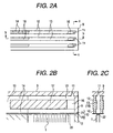
- Fig. 1 is a sectional view of one embodiment of the ink jet recording head 2 using a piezoelement (PZT) of a representative piezoelectric vibrator 1 as an electromechanical transducing element.
- Fig. 2A is a plan view of a pressure generating chamber and Figs. 2B and 2C are enlarged sectional views to show the main part of the recording head 2 shown in Fig. 1.
- the piezoelectric vibrator 1 is inserted into a chamber 4 of a case 3 shaped like a plastic box, for example, through one opening, a tip 1a shaped like comb teeth is made to face an opposite opening, a channel unit 5 is joined to the surface (bottom face) of the case 3 on the opening side, and the tip 1a of the piezoelectric vibrator 1 is abutted against and fixed to a predetermined portion of the channel unit 5.
- numeral 6 denotes a flexible cable and numeral 7 denotes a fixed substrate.
- the channel unit 5 comprises a nozzle plate 9 and a vibration plate 10 laminated on both sides with a channel formation substrate 8 in between.
- the nozzle plate 9 is a stainless thin plate with a plurality of nozzle orifices 11 arranged in rows at pitches corresponding to the dot formation density; in the embodiment, it is formed with five rows of nozzle orifices 11 (96 nozzle orifices per row) made at the pitches of about 0.141 mm (180 dpi).
- the channel formation substrate 8 laminated on one face of the nozzle plate 9 is a plate-like member formed with cavities which is to be pressure generating chambers 13 corresponding to the nozzle orifices 11 in the nozzle plate 9 in a state in which the cavities are partitioned by partition walls 12, and formed with cavities which become ink supply ports 14 and a common ink reservoir 15.
- Each pressure generating chamber 13 is a chamber elongated in a direction orthogonal to the nozzle orifice row; a part of the pressure generating chamber 13 is formed of a through hole 16 which is roughly parallelogrammatic in cross section piercing the channel formation substrate 8 in the thickness direction thereof and the remaining part is formed of a flat concave chamber partitioned up and down by a partition wall 17 formed at the center in the thickness direction of the channel formation substrate 8.
- the pressure generating chamber 13 shown in Fig. 2 is 1216 ⁇ m long and 100 ⁇ m wide on the nozzle plate 9 side and 110 ⁇ m wide on the vibration plate 10 side, the through hole 16 is 100 ⁇ m long and 80 ⁇ m wide, the partition wall 12 on the nozzle plate 9 side is 41 ⁇ m thick, the partition wall 12 on the vibration plate 10 side is 31 ⁇ m thick, and the partition wall 12 of the part of the through hole 16 is 61 ⁇ m thick.
- Numeral 18 denotes a gate formed in the channel from the common ink reservoir 15 to the pressure generating chamber 13 and the gate 18 forms an ink supply passage 14 in the form of a narrow part having a narrow channel width.
- the through hole 16, the pressure generating chamber 13, the ink supply port 14, and the common ink reservoir 15 of the channel formation substrate 8 are formed for each nozzle orifice 11 by etching a silicon wafer.
- the channel formation substrate 8 is made thick, whereby the volume of each pressure generating chamber 13 is increased, whereby the percentage of the compliance of ink in the pressure generating chamber 13 (described later) is made large.
- the through hole 16 is made at one end of the pressure generating chamber 13, namely, at the furthermost portion from the common ink reservoir 15 in the pressure generating chamber 13.
- the ink supply port 14 is connected to an opposite end of the pressure generating chamber 13 and the nozzle orifice 11 is formed in the proximity of the end pad on the opposite side to the ink supply port 14.
- the nozzle orifice 11 is positioned almost at the center of the through hole 16.
- the common ink reservoir 15 is a chamber for supplying ink stored in an ink cartridge (not shown) to each pressure generating chamber 13, and an ink supply tube 19 communicates almost at the center in the longitudinal direction.
- the vibration plate 10 serves as both a seal plate being laminated on an opposite face of the channel formation substrate 8 positioned on the opposite side to the nozzle plate 9 for sealing one opening face of the pressure generating chamber 13 and an elastic film (thin film portion) being laminated on the opposite face of the channel formation substrate 8 for sealing one opening face of the common ink reservoir 15 and is of a double structure comprising a polymer film 21 of PPS, etc., laminated on a stainless plate 20.
- the stainless plate 20 of the portion functioning as the seal member namely, the portion corresponding to the pressure generating chamber 13 is etched to form a thick portion (island portion 22) for abutting and fixing the tip of the piezoelectric vibrator 1, and the stainless plate 20 of the portion functioning as the elastic film, namely, the portion corresponding to the common ink reservoir 15 is removed by etching for leaving only film portion 21 (elastic film).
- the film portion 21 of the vibration plate 10 is made thick, whereby the percentage of the compliance of the vibration plate 10 is relatively lowered and the percentage of the compliance of ink in the pressure generating chamber 13 is relatively raised.
- a polymeric film of PPS (polyphenylene sulfide), polyimide, etc., 3.5 ⁇ m thick was used as film portion 21; in the embodiment, the film 6 ⁇ m thick (twice as thick as the former film) is used.
- the piezoelectric vibrator 1 is expanded in the longitudinal direction of the vibrator, whereby the island portion 22 is pressed against the nozzle plate 9, the film portion (elastic film) 21 surrounding the island portion 22 becomes deformed, and the pressure generating chamber 13 is contracted. If the piezoelectric vibrator 1 is contracted in the longitudinal direction of the vibrator, the pressure generating chamber 13 is expanded due to elasticity of the film portion 21. Expansion and contraction of the pressure generating chamber 13 are controlled, whereby an ink drop is jetted through the nozzle orifice 11.
- a vibration system in the recording head 2 can be represented by an equivalent circuit shown in Fig. 3.
- symbol M denotes inertance of the mass of a medium per unit length [Kg/m 4 ]
- symbol Ma denotes inertance in the piezoelectric vibrator 1
- symbol Mn denotes inertance in the nozzle orifice 11
- symbol Ms denotes inertance in the ink supply port 14.
- Symbol R denotes resistance of the internal loss of a medium [N ⁇ s/m 5 ]
- symbol Rn denotes resistance in the nozzle orifice 11
- symbol Rs denotes resistance in the ink supply port 14.
- Symbol C denotes compliance of volume change per unit pressure [m 5 /N]
- symbol Cc denotes compliance of the vibration plate 10 and the partition wall 12 forming the pressure generating chamber 13
- symbol Ca denotes compliance in the piezoelectric vibrator 1
- symbol Cn denotes compliance in the nozzle plate 9.
- Symbol P denotes pressure generated with time by the piezoelectric vibrator 1, in other words, equivalent pressure into which voltage pulses applied to the piezoelectric vibrator 1 are converted.
- C.ink V ⁇ c 2
- V is the volume [m 3 ] of the pressure generating chamber 13
- ⁇ is the ink density [kgf/m 3 ]
- c is the velocity [m/s] of sound in liquid.
- C.ink kV (k: constant)
- variations in C.ink are mainly caused by the volume of the pressure generating chamber 13. Variations in the volume of the pressure generating chamber 13 depend on the accuracy of finishing of the channel formation substrate 8, but extremely high accuracy can be easily provided by applying an anisotropic etching technique of silicon.
- the compliance of the pressure generating chamber 13 relates to each compliance of the nozzle plate 9, the vibration plate 10, and the partition wall 12 of the channel formation substrate 8 forming the pressure generating chamber 13, namely, functioning as the inner wall face of the pressure generating chamber 13.
- this C.str is volume change ⁇ V relative to pressure change ⁇ P and can be represented as in the following expression (3):
- C.str ⁇ V ⁇ P
- C.str depends on compliance C.film of the film portion of the vibration plate 10.
- C.film is proportional to the cube of the thickness of the film portion 21 and proportional to the fifth power of the width, thus variations in C.str are made large with respect to shape variations.
- the compliance of the recording head becomes hard to be affected by the accuracy of finishing of the pressure generating chamber components such as the partition wall 12 of the channel formation substrate 8 and the vibration plate 10, particularly the work state of the island portion 22 of the vibration plate 10 and an error of the thickness of the film portion 21.
- the volume of the pressure generating chamber 13 may be increased as seen from expression (2).
- the silicon wafer of the channel formation substrate 8 is made thick, whereby the volume in the pressure generating chamber 13 is increased about 40% to 80%, so that the percentage of the compliance of ink in the pressure generating chamber 13 is raised.
- the length in the longitudinal direction may be extended; however, it is desirable to thicken the silicon wafer of the channel formation substrate 8 considering miniaturization of the recording head 2 and the silicon wafer yield.
- the vibration plate 10 is made thick and thus the compliance of the vibration plate 10 becomes smaller than that in the related art, so that the compliance C.str of the pressure generating chamber components decreases, the percentage of the ink compliance C.ink in the pressure generating chamber 13 is still more raised, and variations in the compliance of the recording head 2 can be still more lessened.
- the compliance of the vibration plate 10 accounts for most of the compliance C.str of the pressure generating chamber components, it is important to thicken the vibration plate 10 to relatively decrease the percentage of the compliance C.str of the pressure generating chamber components.
- the volume in the pressure generating chamber 13 is increased and the vibration plate 10 is thickened, whereby the compliance C.film of the vibration plate 10 becomes 29%, the compliance C.cav of the pressure generating chamber 13 of the partition wall 12, etc., becomes 2%, and the ink compliance C.ink in the pressure generating chamber 13 becomes 69%; the compliance C.str of the pressure generating chamber components becomes 31 %. Therefore, the relation of C.ink > C.str is satisfied and when the recording head 2 is assembled, compliance can be easily stabilized. Thus, it contributes greatly to improvement in yield.
- the scope of the invention is not limited to the dimensions mentioned in the embodiment and the relation of C.ink > C.str needs only to be true.
- the piezoelectric vibrator 1 formed of the vibrator like comb teeth in so-called vertical vibration mode comprising the piezoelectric body and internal electrode laminated in the direction orthogonal to the expansion and contraction direction of the vibrator is taken as an example.
- the invention can also be applied to a piezoelectric vibrator 1 in so-called deflection vibration mode comprising the piezoelectric body and internal electrode laminated in the expansion and contraction direction of the vibrator.
- the electromechanical transducing element is not limited to the piezoelectric vibrator and may be an element which produces mechanical deformation as a drive signal is applied.
Landscapes
- Particle Formation And Scattering Control In Inkjet Printers (AREA)
Applications Claiming Priority (2)
| Application Number | Priority Date | Filing Date | Title |
|---|---|---|---|
| JP2330899 | 1999-01-29 | ||
| JP11023308A JP2000218787A (ja) | 1999-01-29 | 1999-01-29 | インクジェット式記録ヘッド及び画像記録装置 |
Publications (2)
| Publication Number | Publication Date |
|---|---|
| EP1024004A1 true EP1024004A1 (de) | 2000-08-02 |
| EP1024004B1 EP1024004B1 (de) | 2002-11-06 |
Family
ID=12106979
Family Applications (1)
| Application Number | Title | Priority Date | Filing Date |
|---|---|---|---|
| EP00101627A Expired - Lifetime EP1024004B1 (de) | 1999-01-29 | 2000-01-28 | Tintenstrahldruckkopf und Bildaufzeichnungsgerät mit diesem Tintenstrahldruckkopf |
Country Status (4)
| Country | Link |
|---|---|
| US (1) | US6702431B1 (de) |
| EP (1) | EP1024004B1 (de) |
| JP (1) | JP2000218787A (de) |
| DE (1) | DE60000697T2 (de) |
Cited By (1)
| Publication number | Priority date | Publication date | Assignee | Title |
|---|---|---|---|---|
| EP1606117A4 (de) * | 2003-03-24 | 2007-12-26 | Ricoh Kk | Aufzeichnungskopf, druckwagen und bilderzeugungsvorrichtung |
Families Citing this family (7)
| Publication number | Priority date | Publication date | Assignee | Title |
|---|---|---|---|---|
| JP4560983B2 (ja) * | 2001-04-05 | 2010-10-13 | セイコーエプソン株式会社 | 静電式インクジェットヘッド |
| ATE435749T1 (de) * | 2002-04-09 | 2009-07-15 | Seiko Epson Corp | Flüssigkeitseinspritzkopf |
| US7387373B2 (en) * | 2002-09-30 | 2008-06-17 | Seiko Epson Corporation | Liquid ejecting head and liquid ejecting apparatus |
| JP2006121798A (ja) | 2004-10-20 | 2006-05-11 | Ishikawajima Harima Heavy Ind Co Ltd | モータ駆動装置 |
| JP5065845B2 (ja) * | 2006-11-10 | 2012-11-07 | 株式会社リコー | 液体吐出ヘッド、液体吐出装置、画像形成装置 |
| KR20080050119A (ko) * | 2006-12-01 | 2008-06-05 | 삼성전자주식회사 | 잉크젯 프린트헤드의 잉크건조방지방법 및 잉크젯 프린터의프린팅 방법 |
| JP2008238594A (ja) * | 2007-03-27 | 2008-10-09 | Seiko Epson Corp | 液体噴射ヘッド、及び、液体噴射装置 |
Citations (7)
| Publication number | Priority date | Publication date | Assignee | Title |
|---|---|---|---|---|
| US4525728A (en) * | 1982-04-27 | 1985-06-25 | Epson Corporation | Ink jet recording head |
| EP0573055A2 (de) * | 1992-06-05 | 1993-12-08 | Seiko Epson Corporation | Tintenstrahlaufzeichnungskopf |
| EP0678387A2 (de) * | 1994-04-20 | 1995-10-25 | Seiko Epson Corporation | Tintenstrahlaufzeichungsgerät und Verfahren zur Herstellung eines Tintenstrahlkopfes |
| EP0728583A2 (de) * | 1995-02-23 | 1996-08-28 | Seiko Epson Corporation | Tintenstrahlaufzeichnungskopf |
| EP0775579A2 (de) * | 1995-10-31 | 1997-05-28 | Seiko Epson Corporation | Laminierter Tintenstrahlaufzeichnungskopf und Betriebsverfahren dafür |
| EP0787589A2 (de) * | 1996-02-05 | 1997-08-06 | Seiko Epson Corporation | Tintenstrahlaufzeichnungskopf |
| EP0893259A2 (de) * | 1997-07-25 | 1999-01-27 | Seiko Epson Corporation | Tintenstrahldruckkopf und sein Herstellungsverfahren |
Family Cites Families (17)
| Publication number | Priority date | Publication date | Assignee | Title |
|---|---|---|---|---|
| JPS5791275A (en) | 1980-11-28 | 1982-06-07 | Seiko Epson Corp | Ink jet head |
| JPS585272A (ja) | 1981-07-02 | 1983-01-12 | Seiko Epson Corp | インクジエツト印刷装置 |
| JPS585271A (ja) | 1981-07-02 | 1983-01-12 | Seiko Epson Corp | インクジエツト印刷装置 |
| JPS585269A (ja) | 1981-07-02 | 1983-01-12 | Seiko Epson Corp | インクジエツト印刷装置 |
| JPS585270A (ja) | 1981-07-02 | 1983-01-12 | Seiko Epson Corp | インクジエツト印刷装置 |
| JPS61141566A (ja) | 1985-11-13 | 1986-06-28 | Seiko Epson Corp | インクジエツトヘツド |
| JPH083172B2 (ja) * | 1986-07-07 | 1996-01-17 | 株式会社ブリヂストン | 水中汚濁防止幕のチエン重錘連結構造 |
| JP3041952B2 (ja) | 1990-02-23 | 2000-05-15 | セイコーエプソン株式会社 | インクジェット式記録ヘッド、圧電振動体、及びこれらの製造方法 |
| JPH0436071A (ja) | 1990-05-31 | 1992-02-06 | Fuji Electric Co Ltd | S形チューブラ水車 |
| JPH0464449A (ja) | 1990-07-03 | 1992-02-28 | Ricoh Co Ltd | インクジェットヘッド |
| JP3147132B2 (ja) * | 1992-03-03 | 2001-03-19 | セイコーエプソン株式会社 | インクジェット記録ヘッド、インクジェット記録ヘッド用振動板、及びインクジェット記録ヘッド用振動板の製造方法 |
| JP3213860B2 (ja) | 1993-05-21 | 2001-10-02 | セイコーエプソン株式会社 | インクジェット式印字ヘッド |
| JP3173281B2 (ja) | 1994-05-25 | 2001-06-04 | セイコーエプソン株式会社 | インクジェット式記録ヘッド |
| JP3484841B2 (ja) | 1994-09-26 | 2004-01-06 | セイコーエプソン株式会社 | インクジェット式記録ヘッド |
| JPH1034921A (ja) | 1996-07-22 | 1998-02-10 | Seiko Epson Corp | インクジェット記録ヘッド、及びインクジェット記録ヘッド用弾性板の製造方法 |
| WO1998022288A1 (en) * | 1996-11-18 | 1998-05-28 | Seiko Epson Corporation | Ink-jet recording head |
| DE69810691T2 (de) * | 1997-04-30 | 2003-08-07 | Seiko Epson Corp., Tokio/Tokyo | Tintenstrahlaufzeichnungskopf |
-
1999
- 1999-01-29 JP JP11023308A patent/JP2000218787A/ja active Pending
-
2000
- 2000-01-28 EP EP00101627A patent/EP1024004B1/de not_active Expired - Lifetime
- 2000-01-28 US US09/493,090 patent/US6702431B1/en not_active Expired - Fee Related
- 2000-01-28 DE DE60000697T patent/DE60000697T2/de not_active Expired - Lifetime
Patent Citations (7)
| Publication number | Priority date | Publication date | Assignee | Title |
|---|---|---|---|---|
| US4525728A (en) * | 1982-04-27 | 1985-06-25 | Epson Corporation | Ink jet recording head |
| EP0573055A2 (de) * | 1992-06-05 | 1993-12-08 | Seiko Epson Corporation | Tintenstrahlaufzeichnungskopf |
| EP0678387A2 (de) * | 1994-04-20 | 1995-10-25 | Seiko Epson Corporation | Tintenstrahlaufzeichungsgerät und Verfahren zur Herstellung eines Tintenstrahlkopfes |
| EP0728583A2 (de) * | 1995-02-23 | 1996-08-28 | Seiko Epson Corporation | Tintenstrahlaufzeichnungskopf |
| EP0775579A2 (de) * | 1995-10-31 | 1997-05-28 | Seiko Epson Corporation | Laminierter Tintenstrahlaufzeichnungskopf und Betriebsverfahren dafür |
| EP0787589A2 (de) * | 1996-02-05 | 1997-08-06 | Seiko Epson Corporation | Tintenstrahlaufzeichnungskopf |
| EP0893259A2 (de) * | 1997-07-25 | 1999-01-27 | Seiko Epson Corporation | Tintenstrahldruckkopf und sein Herstellungsverfahren |
Cited By (1)
| Publication number | Priority date | Publication date | Assignee | Title |
|---|---|---|---|---|
| EP1606117A4 (de) * | 2003-03-24 | 2007-12-26 | Ricoh Kk | Aufzeichnungskopf, druckwagen und bilderzeugungsvorrichtung |
Also Published As
| Publication number | Publication date |
|---|---|
| JP2000218787A (ja) | 2000-08-08 |
| EP1024004B1 (de) | 2002-11-06 |
| US6702431B1 (en) | 2004-03-09 |
| DE60000697T2 (de) | 2003-07-03 |
| DE60000697D1 (de) | 2002-12-12 |
Similar Documents
| Publication | Publication Date | Title |
|---|---|---|
| US7673953B2 (en) | Liquid ejection apparatus for suppressing a decrease in speed of liquid droplets which are discharged from adjacent nozzles during the same discharge period | |
| EP1606117B1 (de) | Aufzeichnungskopf, druckwagen und bilderzeugungsvorrichtung | |
| US6729716B2 (en) | Liquid drop jet head and ink jet recording apparatus | |
| US6779866B2 (en) | Liquid jetting apparatus and method for driving the same | |
| US6715852B2 (en) | Liquid jetting apparatus | |
| US6598950B1 (en) | Ink jet recording apparatus and method of driving ink jet recording head incorporated in the same | |
| US20100053252A1 (en) | Liquid discharging apparatus and method of controlling liquid discharging apparatus | |
| US6386664B1 (en) | Ink-jet recording apparatus | |
| US7178893B2 (en) | Head controller, inkjet recording apparatus, and image recording apparatus that prevent degradation in image quality due to environmental temperature changes | |
| US7699421B2 (en) | Liquid ejecting apparatus | |
| JP3842568B2 (ja) | 液体噴射装置 | |
| US6702431B1 (en) | Ink jet recording head and image recording apparatus incorporating the same | |
| US6460959B1 (en) | Ink jet recording apparatus | |
| US7374263B2 (en) | Liquid ejecting apparatus | |
| JP4296796B2 (ja) | 液体噴射装置、及び、その液滴吐出制御方法 | |
| US7055921B2 (en) | Method for driving liquid-jet head and liquid-jet apparatus | |
| US7748811B2 (en) | Liquid jet apparatus | |
| US6905184B2 (en) | Liquid jetting apparatus | |
| JP2004090542A (ja) | インクジェット記録装置 | |
| JP2007098820A (ja) | 液体噴射装置、及び、その制御方法 | |
| JP3405309B2 (ja) | アクチュエータ装置及びインクジェット式記録装置、およびそれらを駆動させるためのプログラムが格納された記録媒体 | |
| JP3959704B2 (ja) | 液体噴射装置 | |
| JP2002347249A (ja) | インクジェット式記録ヘッド及び画像記録装置 | |
| JP2007152665A (ja) | 液体噴射ヘッド、及び、液体噴射装置 | |
| JP2001341297A (ja) | 液体噴射装置 |
Legal Events
| Date | Code | Title | Description |
|---|---|---|---|
| PUAI | Public reference made under article 153(3) epc to a published international application that has entered the european phase |
Free format text: ORIGINAL CODE: 0009012 |
|
| AK | Designated contracting states |
Kind code of ref document: A1 Designated state(s): DE FR GB IT NL |
|
| AX | Request for extension of the european patent |
Free format text: AL;LT;LV;MK;RO;SI |
|
| 17P | Request for examination filed |
Effective date: 20000817 |
|
| 17Q | First examination report despatched |
Effective date: 20001020 |
|
| AKX | Designation fees paid |
Free format text: DE FR GB IT NL |
|
| GRAG | Despatch of communication of intention to grant |
Free format text: ORIGINAL CODE: EPIDOS AGRA |
|
| GRAG | Despatch of communication of intention to grant |
Free format text: ORIGINAL CODE: EPIDOS AGRA |
|
| GRAH | Despatch of communication of intention to grant a patent |
Free format text: ORIGINAL CODE: EPIDOS IGRA |
|
| GRAH | Despatch of communication of intention to grant a patent |
Free format text: ORIGINAL CODE: EPIDOS IGRA |
|
| GRAA | (expected) grant |
Free format text: ORIGINAL CODE: 0009210 |
|
| AK | Designated contracting states |
Kind code of ref document: B1 Designated state(s): DE FR GB IT NL |
|
| REG | Reference to a national code |
Ref country code: GB Ref legal event code: FG4D |
|
| REF | Corresponds to: |
Ref document number: 60000697 Country of ref document: DE Date of ref document: 20021212 |
|
| ET | Fr: translation filed | ||
| PLBE | No opposition filed within time limit |
Free format text: ORIGINAL CODE: 0009261 |
|
| STAA | Information on the status of an ep patent application or granted ep patent |
Free format text: STATUS: NO OPPOSITION FILED WITHIN TIME LIMIT |
|
| 26N | No opposition filed |
Effective date: 20030807 |
|
| PGFP | Annual fee paid to national office [announced via postgrant information from national office to epo] |
Ref country code: DE Payment date: 20110126 Year of fee payment: 12 Ref country code: IT Payment date: 20110125 Year of fee payment: 12 Ref country code: FR Payment date: 20110128 Year of fee payment: 12 Ref country code: NL Payment date: 20110120 Year of fee payment: 12 |
|
| PGFP | Annual fee paid to national office [announced via postgrant information from national office to epo] |
Ref country code: GB Payment date: 20110126 Year of fee payment: 12 |
|
| REG | Reference to a national code |
Ref country code: NL Ref legal event code: V1 Effective date: 20120801 |
|
| GBPC | Gb: european patent ceased through non-payment of renewal fee |
Effective date: 20120128 |
|
| REG | Reference to a national code |
Ref country code: FR Ref legal event code: ST Effective date: 20120928 |
|
| PG25 | Lapsed in a contracting state [announced via postgrant information from national office to epo] |
Ref country code: GB Free format text: LAPSE BECAUSE OF NON-PAYMENT OF DUE FEES Effective date: 20120128 Ref country code: DE Free format text: LAPSE BECAUSE OF NON-PAYMENT OF DUE FEES Effective date: 20120801 |
|
| REG | Reference to a national code |
Ref country code: DE Ref legal event code: R119 Ref document number: 60000697 Country of ref document: DE Effective date: 20120801 |
|
| PG25 | Lapsed in a contracting state [announced via postgrant information from national office to epo] |
Ref country code: IT Free format text: LAPSE BECAUSE OF NON-PAYMENT OF DUE FEES Effective date: 20120128 |
|
| PG25 | Lapsed in a contracting state [announced via postgrant information from national office to epo] |
Ref country code: FR Free format text: LAPSE BECAUSE OF NON-PAYMENT OF DUE FEES Effective date: 20120131 |
|
| PG25 | Lapsed in a contracting state [announced via postgrant information from national office to epo] |
Ref country code: NL Free format text: LAPSE BECAUSE OF NON-PAYMENT OF DUE FEES Effective date: 20120801 |