EP1018377A2 - Verfahren und Vorrichtung zum Entzundern einer Oszillationsmarken aufweisenden Oberfläche eines Gussstranges aus einer Stranggiessanlage - Google Patents
Verfahren und Vorrichtung zum Entzundern einer Oszillationsmarken aufweisenden Oberfläche eines Gussstranges aus einer Stranggiessanlage Download PDFInfo
- Publication number
- EP1018377A2 EP1018377A2 EP99124715A EP99124715A EP1018377A2 EP 1018377 A2 EP1018377 A2 EP 1018377A2 EP 99124715 A EP99124715 A EP 99124715A EP 99124715 A EP99124715 A EP 99124715A EP 1018377 A2 EP1018377 A2 EP 1018377A2
- Authority
- EP
- European Patent Office
- Prior art keywords
- cast strand
- deflection
- strand
- descaling
- cast
- Prior art date
- Legal status (The legal status is an assumption and is not a legal conclusion. Google has not performed a legal analysis and makes no representation as to the accuracy of the status listed.)
- Granted
Links
- 238000000034 method Methods 0.000 title claims abstract description 31
- 230000010355 oscillation Effects 0.000 title claims description 19
- 238000009749 continuous casting Methods 0.000 title claims description 12
- 238000009434 installation Methods 0.000 title 1
- 238000004140 cleaning Methods 0.000 claims abstract description 9
- 230000008569 process Effects 0.000 claims abstract description 9
- 239000008233 hard water Substances 0.000 claims abstract description 5
- 239000007921 spray Substances 0.000 claims description 27
- XLYOFNOQVPJJNP-UHFFFAOYSA-N water Substances O XLYOFNOQVPJJNP-UHFFFAOYSA-N 0.000 claims description 26
- 238000005452 bending Methods 0.000 claims description 14
- 238000005096 rolling process Methods 0.000 claims description 8
- 238000006073 displacement reaction Methods 0.000 claims description 4
- 238000001816 cooling Methods 0.000 claims description 3
- 239000000463 material Substances 0.000 claims description 3
- 230000001681 protective effect Effects 0.000 claims description 3
- 238000012544 monitoring process Methods 0.000 claims description 2
- 238000005520 cutting process Methods 0.000 claims 1
- 238000005266 casting Methods 0.000 abstract description 7
- 230000000694 effects Effects 0.000 description 3
- 230000008901 benefit Effects 0.000 description 2
- 238000005516 engineering process Methods 0.000 description 2
- 230000006872 improvement Effects 0.000 description 2
- 239000002245 particle Substances 0.000 description 2
- 230000008859 change Effects 0.000 description 1
- 238000011109 contamination Methods 0.000 description 1
- 238000007688 edging Methods 0.000 description 1
- 239000012535 impurity Substances 0.000 description 1
- 230000003993 interaction Effects 0.000 description 1
- 239000000314 lubricant Substances 0.000 description 1
- 239000000843 powder Substances 0.000 description 1
- 230000001105 regulatory effect Effects 0.000 description 1
- 230000002441 reversible effect Effects 0.000 description 1
- 230000008961 swelling Effects 0.000 description 1
- 230000007704 transition Effects 0.000 description 1
Images

Classifications
-
- B—PERFORMING OPERATIONS; TRANSPORTING
- B21—MECHANICAL METAL-WORKING WITHOUT ESSENTIALLY REMOVING MATERIAL; PUNCHING METAL
- B21B—ROLLING OF METAL
- B21B45/00—Devices for surface or other treatment of work, specially combined with or arranged in, or specially adapted for use in connection with, metal-rolling mills
- B21B45/04—Devices for surface or other treatment of work, specially combined with or arranged in, or specially adapted for use in connection with, metal-rolling mills for de-scaling, e.g. by brushing
- B21B45/08—Devices for surface or other treatment of work, specially combined with or arranged in, or specially adapted for use in connection with, metal-rolling mills for de-scaling, e.g. by brushing hydraulically
-
- B—PERFORMING OPERATIONS; TRANSPORTING
- B21—MECHANICAL METAL-WORKING WITHOUT ESSENTIALLY REMOVING MATERIAL; PUNCHING METAL
- B21B—ROLLING OF METAL
- B21B1/00—Metal-rolling methods or mills for making semi-finished products of solid or profiled cross-section; Sequence of operations in milling trains; Layout of rolling-mill plant, e.g. grouping of stands; Succession of passes or of sectional pass alternations
- B21B1/46—Metal-rolling methods or mills for making semi-finished products of solid or profiled cross-section; Sequence of operations in milling trains; Layout of rolling-mill plant, e.g. grouping of stands; Succession of passes or of sectional pass alternations for rolling metal immediately subsequent to continuous casting
-
- B—PERFORMING OPERATIONS; TRANSPORTING
- B21—MECHANICAL METAL-WORKING WITHOUT ESSENTIALLY REMOVING MATERIAL; PUNCHING METAL
- B21B—ROLLING OF METAL
- B21B45/00—Devices for surface or other treatment of work, specially combined with or arranged in, or specially adapted for use in connection with, metal-rolling mills
- B21B45/004—Heating the product
-
- B—PERFORMING OPERATIONS; TRANSPORTING
- B21—MECHANICAL METAL-WORKING WITHOUT ESSENTIALLY REMOVING MATERIAL; PUNCHING METAL
- B21B—ROLLING OF METAL
- B21B45/00—Devices for surface or other treatment of work, specially combined with or arranged in, or specially adapted for use in connection with, metal-rolling mills
- B21B45/04—Devices for surface or other treatment of work, specially combined with or arranged in, or specially adapted for use in connection with, metal-rolling mills for de-scaling, e.g. by brushing
-
- Y—GENERAL TAGGING OF NEW TECHNOLOGICAL DEVELOPMENTS; GENERAL TAGGING OF CROSS-SECTIONAL TECHNOLOGIES SPANNING OVER SEVERAL SECTIONS OF THE IPC; TECHNICAL SUBJECTS COVERED BY FORMER USPC CROSS-REFERENCE ART COLLECTIONS [XRACs] AND DIGESTS
- Y10—TECHNICAL SUBJECTS COVERED BY FORMER USPC
- Y10T—TECHNICAL SUBJECTS COVERED BY FORMER US CLASSIFICATION
- Y10T29/00—Metal working
- Y10T29/45—Scale remover or preventor
- Y10T29/4517—Rolling deformation or deflection
-
- Y—GENERAL TAGGING OF NEW TECHNOLOGICAL DEVELOPMENTS; GENERAL TAGGING OF CROSS-SECTIONAL TECHNOLOGIES SPANNING OVER SEVERAL SECTIONS OF THE IPC; TECHNICAL SUBJECTS COVERED BY FORMER USPC CROSS-REFERENCE ART COLLECTIONS [XRACs] AND DIGESTS
- Y10—TECHNICAL SUBJECTS COVERED BY FORMER USPC
- Y10T—TECHNICAL SUBJECTS COVERED BY FORMER US CLASSIFICATION
- Y10T29/00—Metal working
- Y10T29/45—Scale remover or preventor
- Y10T29/4533—Fluid impingement
- Y10T29/4544—Liquid jet
Definitions
- the invention relates to a method for descaling, in particular oscillation marks having surfaces of a producible in the continuous casting process Cast strand, especially of thin slabs, in a subsequent Hot strip mill with leveling furnace and preferably with several rolling stands be reduced in thickness. Furthermore, the invention relates to a device for Implementation of the method according to the invention.
- the invention is based on the object of specifying a method and a device, through which the difficulty in cleaning the surfaces of Continuous casting products, especially for thin slabs, and there particularly and be overcome in the oscillation marks.
- One is also said to be undesirable strong cooling effect in the cast product using the smallest possible quantities can be prevented by pressurized water.
- One embodiment of the invention provides that the cast strand is sinusoidal for this purpose or is deflected approximately sinusoidally.
- Such a sinusoidal or approximately sinusoidal deflection is guaranteed an almost uniform swelling and decay of the surface tension, thereby avoiding damage to the cast structure.
- a further embodiment of the method provides that the extent of each distraction of the cast strand in accordance with the maximum permissible reversible Deformation of the cast strand is made.
- Another embodiment of the method according to the invention provides that Extent of each deflection of the cast strand in accordance with the maximum permissible Surface tension of the strand is made.
- a further embodiment of the process provides that the Extent of each deflection of the cast strand in accordance with the material temperature of the cast strand is carried out under constant temperature control.
- the method according to the invention further provides that the distance between the spray nozzles and the water-irradiated surface of the cast strand is continuously measured and kept constant. So that the working parameters largely constant when using the hard cleaning jets of water held.
- An advantageous embodiment of the method further provides that the cast strand with a number each running in parallel planes and in series arranged water jets is applied, the planes at an angle one of the planes perpendicular to the direction of transport of the cast strand lie and the water jets can be aligned obliquely to the surface of the cast strand are.
- a further improvement in the cleaning effect can also be achieved in this way be that the water jets with the spray nozzles they generate the spray bars can be moved back and forth in the spray plane.
- the Measure be made use of that according to the structural condition of the cast strand in accordance with the cooling that takes place with descaling changing deflection force measured continuously and then the amount of water to be added while maintaining the product of the amount of water and water pressure is set constantly.
- This also compensates for parameter changes that are occasionally made by the Casting machine can run out, for example, due to a change in the casting speed or the casting temperature.
- the cast strand in a subsequent hot strip mill with a compensating furnace and is reduced in thickness with several roll stands is in the end Strand support and before entering the equalization furnace or before entering the rolling stands between a pair of directional driver rollers on the inlet side and one Pair of exit-side bending driver rollers present a descaling station that at least two spaced apart in the transport direction of the cast strand has opposite deflection bending rollers, which on each opposite side of the Cast strand spray bar with spray nozzles arranged in an inclined plane assigned.
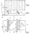
- the area of a continuous caster shown in FIG. 1 shows the continuous caster 28 with downstream strand support 10 for guiding and supporting the Cast strand 1 in particular a thin slab.
- the thin slab is behind the continuous caster in a hot strip mill 32 with equalizing furnace 11 and with several rolling stands 33 reduced thickness. Between the equalization furnace 11 and A cropping shear 31 is arranged on the first roll stand 33.
- This one Deflection bending rollers are a spray bar 17 on each opposite side of the slab, 18 associated with spray nozzles 6, 7 arranged in inclined planes, like this can be seen from Figures 3b and 4.
- the spray bars 17, 18 are, for example.
- Distance sensors 19, 20 and distance adjusting means 21, 22 are assigned. So that can the distance between the spray nozzles 6 and 7 and the surface 2, 3 of the Thin slab 1 are kept exactly constant.
- the deflection bending rollers 15, 16 are controlled actuating cylinders 23, 24 and displacement sensors 25, 26 assigned.
- the deflection bending rollers 15, 16 can thus either be regulated away or load-controlled adjustable distance.
- the descaling station 14 is covered with a protective box 27.
- the deflection bending rollers 15, 16 can be adjusted by means of the corresponding adjusting means 23-26 achieved that the extent of each deflection 4, 5 of the thin slab 1 after Provided their maximum allowable deformation is made.
- the water jets 8, 9 can also be sprayed with the spray bar 17, 18 can be moved back and forth in the plane y-y.
- the water jets 8,9 either according to FIG. 3b or FIG. 4 obliquely against the transport direction 34 the slab 1 be directed. However, they can also be aligned with the transport direction 34 be, the choice of this orientation depending on the prevailing Operating parameters can be set by the specialist from case to case.
- the descaling device with the claims Features (Fig. 2) also before the entry of the thin slab in the roll stands 33 are provided.
Abstract
Description
- daß der Gußstrang zwischen dem Ende der Strangstützung und vor dem Einlauf in den Ausgleichsofen oder vor dem Einlauf in die Walzgerüste in einem begrenzten Bereich durch wenigstens zweifaches Auslenken aus seiner horizontalen Transportrichtung im Bereich jeder Auslenkung einer Dehnung seiner Oberflächen unterworfen wird, und
- daß die Strangoberflächen insbesondere in den Auslenkungsbereichen mittels harter Wasserstrahlen einer intensiven Abreinigung unterzogen werden.
- Figur 1
- eine Stranggießanlage mit darin angeordneter Vorrichtung zum Entzundern von Oszillationsmarken aufweisenden Oberflächen einer im Stranggießverfahren herstellbaren Dünnbramme in schematischer Darstellung;
- Figur 2
- in Seitenansicht und in vergrößertem Maßstab die Entzunderungsstation gemäß Fig. 1,
- Figur 3 a
- eine Draufsicht auf die Oberfläche einer Dünnbramme mit Oszillationsmarken,
- Figur 3 b
- das Strangstück gemäß Fig. 3a in Seitenansicht,
- Figur 4
- In Draufsicht ein Stück einer Dünnbramme mit darüber angeordneten Spritzbalken und Spritzdüsen.
- 1
- Gußstrang, Dünnbramme
- 2
- Oberfläche
- 3
- Oberfläche
- 4
- Auslenkung
- 5
- Auslenkung
- 6
- Spritzdüse
- 7
- Spritzdüse
- 8
- Wasserstrahl
- 9
- Wasserstrahl
- 10
- Strangstützung
- 11
- Ausgleichsofen
- 12
- Richttreiberrollen
- 13
- Biegetreiberrollen
- 14
- Entzunderungsstation
- 15
- Auslenk-Biegerolle
- 16
- Auslenk-Biegerolle
- 17
- Spritzbalken
- 18
- Spritzbalken
- 19
- Abstandsfühler
- 20
- Abstandsfühler
- 21
- Stellmittel
- 22
- Stellmittel
- 23
- Stellzylinder
- 24
- Stellzylinder
- 25
- Weggeber
- 26
- Weggeber
- 27
- Schutzkasten
- 28
- Stranggießmaschine
- 29
- Auslenkungsbereich
- 30
- Oszillationsmarken
- 31
- Schere
- 32
- Warmbandstraße
- 33
- Walzgerüste
- 34
- Gießrichtung/Transportrichtung
Claims (15)
- Verfahren zum Entzundern, insbesondere von Oszillationsmarken (30) aufweisenden Oberflächen (2, 3) eines im Stranggießverfahren herstellbaren Gußstranges (1), insbesondere von Dünnbrammen, die in einer nachfolgenden Warmbandstraße (32) mit Ausgleichsofen (11) und mit vorzugsweise mehreren Walzgerüsten (33) dickenreduziert werden,
dadurch gekennzeichnet,daß der Gußstrang (1) zwischen dem Ende der Strangstützung (10) und vor dem Einlauf in den Ausgleichsofen (11) oder vor dem Einlauf in die Walzgerüste (33) in einem begrenzten Bereich (29) durch wenigstens zweifaches Auslenken aus seiner horizontalen Transportrichtung im Bereich jeder Auslenkung (4, 5) einer Dehnung seiner Oberflächen (2,3) unterworfen wird, unddaß die Strangoberflächen (2, 3) insbesondere in den Auslenkungsbereichen (4, 5) mittels harter Wasserstrahlen (8, 9) einer intensiven Abreinigung unterzogen werden. - Verfahren nach Anspruch 1
dadurch gekennzeichnet,
daß der Gußstrang (1) sinusförmig oder annähernd sinusförmig ausgelenkt wird. - Verfahren nach Anspruch 1 oder 2,
dadurch gekennzeichnet,
daß das Ausmaß jeder Auslenkung (4, 5) des Gußstranges (1) nach Maßgabe der maximal zulässigen Verformung des Gußstranges (1) vorgenommen wird. - Verfahren nach Anspruch 1 oder 2,
dadurch gekennzeichnet,
daß das Ausmaß jeder Auslenkung (4, 5) des Gußstranges (1) nach Maßgabe der maximal zulässigen Oberflächenspannung des Gußstranges (1) vorgenommen wird. - Verfahren nach Anspruch 1 oder 2,
dadurch gekennzeichnet,
daß das Ausmaß jeder Auslenkung (4, 5) des Gußstranges (1) nach Maßgabe der Materialtemperatur des Gußstranges (1) unter ständiger Temperaturkontrolle vorgenommen wird. - Verfahren nach einem oder mehreren der Ansprüche 1 bis 5,
dadurch gekennzeichnet, ,
daß die Entfernung zwischen Spritzdüsen (6, 7) und der wasserbestrahlten Oberfläche (2, 3) des Gußstranges (1) fortlaufend gemessen und konstant gehalten wird. - Verfahren nach einem oder mehreren der Ansprüche 1 bis 6,
dadurch gekennzeichnet, ,
daß der Druck des Spritzwasser fortlaufend kontrolliert und auf hohem Druckniveau gehalten wird. - Verfahren nach einem oder mehreren der Ansprüche 1 bis 7,
dadurch gekennzeichnet, ,
daß der Gußstrang (1) mit einer Anzahl jeweils in parallelen Ebenen (x-x) verlaufenden und in Reihe angeordneten Wasserstrahlen (,8, 9) beaufschlagt wird, wobei die Ebenen (x-x) im Winkel (α bzw. β) zu einer die Transportrichtung des Gußstranges (1) senkrecht schneidenden Ebene (y-y) liegen und die Wasserstrahlen (8, 9) schräg zur Oberfläche (2, 3) des Gußstranges (1) ausrichtbar sind. - Verfahren nach Anspruch 8,
dadurch gekennzeichnet,
daß die Wasserstrahlen (8, 9) mit den sie erzeugenden Spritzdüsen (6, 7) der Spritzbalken (17, 18) in der Ebene (y-y) hin- und herbewegbar sind. - Verfahren nach einem oder mehreren der Ansprüche 1 bis 9,
dadurch gekennzeichnet,
daß die nach Maßgabe des Gefügezustandes des Gußstranges (1) entsprechend der mit der Entzunderung stattfindenden Abkühlung sich ändernde Auslenkungskraft fortlaufend gemessen und danach die aufzugebende Wassermenge unter Aufrechterhaltung des Produkts aus Wassermenge und Wasserdruck konstant eingestellt wird. - Vorrichtung zum Entzundern von insbesondere Oszillationsmarken (20) aufweisenden Oberflächen (2, 3) eines im Stranggießverfahren herstellbaren Gußstranges (1), insbesondere von Dünnbrammen zur Durchführung des Verfahrens nach den Ansprüchen 1 bis 10, wobei der Gußstrang (1) in einer nachfolgenden Warmbandstraße (32) mit Ausgleichsofen (11) und mit vorzugsweise mehreren Walzgerüsten (33) dickenreduziert wird,
dadurch gekennzeichnet,
daß am Ende der Strangstützung (10) und vor dem Einlauf in den Ausgleichsofen (11) oder vor dem Einlauf in die Walzgerüste (33) zwischen einem Paar einlaufseitiger Richttreiberrollen (12) und einem Paar auslaufseitiger Biegetreiberrollen (13) eine Entzunderungsstation (14) vorhanden ist, die wenigstens zwei in Transportrichtung des Gußstranges (1) beabstandete, einander entgegengerichtete Auslenk-Biegerollen (15, 16) besitzt, welchen auf jeder Gegenseite des Gußstranges (1) Spritzbalken (17, 18) mit in einer schrägen Ebene angeordneten Spritzdüsen (6, 7) zugeordnet sind. - Vorrichtung nach Anspruch 11,
dadurch gekennzeichnet, ,
daß den Spritzbalken (17, 18) Abstandsfühler (19, 20) sowie Abstands-Stellmittel (21, 22) zugeordnet sind. - Vorrichtung nach Anspruch 11 oder 12,
dadurch gekennzeichnet,
daß den Auslenk-Biegerollen (15, 16) geregelte Stellzylinder (23, 24) und Weggeber (25, 26) zugeordnet sind. - Vorrichtung nach einem oder mehreren der Ansprüche 11 bis 13,
dadurch gekennzeichnet,
daß den Stellzylindern (23, 24) Kontrollmittel zur Überwachung der Auslenk-Kräfte zugeordnet sind. - Vorrichtung nach einem oder mehreren der Ansprüche 11 bis 14,
dadurch gekennzeichnet,
daß die Entzunderungsstation (14) mit einem Schutzkasten (27) umkleidet ist.
Applications Claiming Priority (2)
| Application Number | Priority Date | Filing Date | Title |
|---|---|---|---|
| DE19900427 | 1999-01-08 | ||
| DE19900427A DE19900427A1 (de) | 1999-01-08 | 1999-01-08 | Verfahren und Vorrichtung zum Entzundern einer Oszillationsmarken aufweisenden Oberfläche eines Gußstranges aus einer Stranggießanlage |
Publications (3)
| Publication Number | Publication Date |
|---|---|
| EP1018377A2 true EP1018377A2 (de) | 2000-07-12 |
| EP1018377A3 EP1018377A3 (de) | 2003-09-17 |
| EP1018377B1 EP1018377B1 (de) | 2005-07-06 |
Family
ID=7893764
Family Applications (1)
| Application Number | Title | Priority Date | Filing Date |
|---|---|---|---|
| EP99124715A Expired - Lifetime EP1018377B1 (de) | 1999-01-08 | 1999-12-11 | Verfahren und Vorrichtung zum Entzundern einer Oszillationsmarken aufweisenden Oberfläche eines Gussstranges aus einer Stranggiessanlage |
Country Status (7)
| Country | Link |
|---|---|
| US (1) | US6389666B1 (de) |
| EP (1) | EP1018377B1 (de) |
| JP (1) | JP4637986B2 (de) |
| KR (1) | KR100648498B1 (de) |
| CN (1) | CN1260253A (de) |
| AT (1) | ATE299050T1 (de) |
| DE (2) | DE19900427A1 (de) |
Cited By (5)
| Publication number | Priority date | Publication date | Assignee | Title |
|---|---|---|---|---|
| EP1059127A2 (de) * | 1999-06-07 | 2000-12-13 | SMS Schloemann-Siemag AG | Entzunderungsverfahren für ein Metallband und hiermit korrespondierende Entzunderungsanordnung |
| KR100648498B1 (ko) * | 1999-01-08 | 2006-11-24 | 에스엠에스 데마그 악티엔게젤샤프트 | 연속주조기에 의하여 생산된 주조 빌릿의 진동 연흔을가진 표면을 디스케일링하는 방법 및 장치 |
| CN101811145A (zh) * | 2010-04-23 | 2010-08-25 | 东莞市科力钢铁线材有限公司 | 振动剥壳装置 |
| ITMI20110368A1 (it) * | 2011-03-10 | 2012-09-11 | Danieli Off Mecc | Discagliatore oscillante e metodo per discagliare un semilavorato metallurgico |
| CN107931328A (zh) * | 2017-11-20 | 2018-04-20 | 江苏省冶金设计院有限公司 | 一种双带钢生产工艺 |
Families Citing this family (24)
| Publication number | Priority date | Publication date | Assignee | Title |
|---|---|---|---|---|
| DE10110324A1 (de) * | 2001-03-03 | 2002-09-05 | Sms Demag Ag | Verfahren zum Entzundern von Bändern |
| KR100928820B1 (ko) * | 2002-12-28 | 2009-11-27 | 주식회사 포스코 | 전기강판제조용 열연소둔강판의 산화막 제거방법,전기강판제조용 열연소둔강판의 제조방법 및 장치 |
| EP1486348B1 (de) * | 2003-06-12 | 2013-01-02 | FUJIFILM Manufacturing Europe B.V. | Verfahren zur Herstellung einer Flachdruckplatte |
| KR100598972B1 (ko) * | 2004-05-07 | 2006-07-13 | 주식회사 경도공업 | 사상압연기용 롤러가이드의 동작감시장치 및 방법 |
| AT504782B1 (de) | 2005-11-09 | 2008-08-15 | Siemens Vai Metals Tech Gmbh | Verfahren zur herstellung eines warmgewalzten stahlbandes und kombinierte giess- und walzanlage zur durchführung des verfahrens |
| DE102008047029A1 (de) * | 2008-09-13 | 2010-03-18 | Sms Siemag Aktiengesellschaft | Entzunderungsvorrichtung |
| AT507663B1 (de) | 2009-04-09 | 2010-07-15 | Siemens Vai Metals Tech Gmbh | Verfahren und vorrichtung zum aufbereiten von warmwalzgut |
| DE102009035161A1 (de) * | 2009-07-29 | 2011-02-10 | Sms Siemag Ag | Verfahren und Vorrichtung zur Entzunderung oder Reinigung von metallischen Oberflächen, unter anderem Bänder (oder Brammen) im Durchlauf |
| DE102010004563A1 (de) * | 2010-01-14 | 2011-07-21 | SMS Siemag AG, 40237 | Verfahren und Vorrichtung zur Inline-Oberflächenbehandlung von Brammen |
| CN102189135A (zh) * | 2010-03-16 | 2011-09-21 | 宝山钢铁股份有限公司 | 快速去除冷态带钢表面氧化铁皮系统及方法 |
| CN102728633A (zh) * | 2011-04-07 | 2012-10-17 | 福建金锋钢业有限公司 | 一种钢带破鳞矫直设备 |
| CN103418623B (zh) * | 2012-05-25 | 2016-06-01 | 宝山钢铁股份有限公司 | 一种冷态金属板带表面处理系统及其处理方法 |
| RU2630106C2 (ru) * | 2013-03-08 | 2017-09-05 | Смс Груп Гмбх | Способ изготовления металлической полосы посредством непрерывной разливки и прокатки |
| CN103481201A (zh) * | 2013-10-16 | 2014-01-01 | 山西太钢不锈钢股份有限公司 | 金属板带表面连续除鳞的装置与方法 |
| KR101558936B1 (ko) | 2013-12-26 | 2015-10-12 | 재단법인 포항산업과학연구원 | 장력 유지 시스템 및 이를 이용한 장력 유지 방법 |
| CN103962413A (zh) * | 2014-04-18 | 2014-08-06 | 江苏胜达科技有限公司 | 一种钢丝机械除鳞装置 |
| CN104759474B (zh) * | 2015-03-10 | 2016-08-24 | 北京科技大学 | 一种基于磨料射流的带钢脱脂控制装置 |
| US10376912B2 (en) * | 2018-01-02 | 2019-08-13 | Alex Xie | Apparatus and method for depositing color into cracks of a moving formed quartz slab to create veins in an engineered stone |
| US10099236B1 (en) * | 2018-01-02 | 2018-10-16 | Alex Xie | Apparatus and method for spraying color into cracks of a moving formed quartz slab to create veins in an engineered stone |
| CN108405634B (zh) * | 2018-02-27 | 2020-02-21 | 首钢京唐钢铁联合有限责任公司 | 一种增加板坯过程温降的方法 |
| US10300630B1 (en) | 2018-12-20 | 2019-05-28 | Alex Xie | Cutting equipment and its controllers |
| CN112743456B (zh) * | 2020-11-27 | 2022-04-08 | 北京电子科技职业学院 | 一种带钢无酸除鳞装置 |
| CN113182351B (zh) * | 2021-04-15 | 2023-04-11 | 首钢集团有限公司 | 一种热连轧机振动振纹的发生位置判别方法和装置 |
| CN113145672A (zh) * | 2021-05-17 | 2021-07-23 | 山东绿钢环保科技股份有限公司 | 用于钢带的高效除鳞系统 |
Citations (6)
| Publication number | Priority date | Publication date | Assignee | Title |
|---|---|---|---|---|
| JPS5881511A (ja) * | 1981-11-06 | 1983-05-16 | Nisshin Steel Co Ltd | 熱延鋼板のデスケ−リングノズルのセツト方法 |
| DE3150946A1 (de) * | 1981-12-23 | 1983-07-14 | Woma-Apparatebau Wolfgang Maasberg & Co Gmbh, 4100 Duisburg | "vorrichtung zum entzundern eines stahlstrangs" |
| JPS61269925A (ja) * | 1985-05-24 | 1986-11-29 | Kawasaki Steel Corp | 熱間圧延におけるスケ−ル除去方法 |
| JPH01154816A (ja) * | 1987-12-14 | 1989-06-16 | Mitsubishi Corp | ロールベンドスケールブレーカにおけるスケール除去方法とその装置 |
| EP0360480A2 (de) * | 1988-09-20 | 1990-03-28 | Hitachi, Ltd. | Entzundern von Walzgut |
| JPH06315712A (ja) * | 1993-05-10 | 1994-11-15 | Ishikawajima Harima Heavy Ind Co Ltd | 熱間圧延設備 |
Family Cites Families (10)
| Publication number | Priority date | Publication date | Assignee | Title |
|---|---|---|---|---|
| US3209429A (en) * | 1958-02-17 | 1965-10-05 | August Seuthe Maschf | Method and apparatus for descaling strip material, especially strip iron |
| US3518736A (en) * | 1968-07-29 | 1970-07-07 | Gen Electric | Rolling mill descaling device |
| US5272798A (en) * | 1992-08-05 | 1993-12-28 | Kolene Corporation | Method and apparatus for descaling metal strip |
| JP3174457B2 (ja) * | 1994-05-17 | 2001-06-11 | 株式会社日立製作所 | 連鋳直結熱間圧延設備およびその圧延方法 |
| JPH0839130A (ja) * | 1994-07-29 | 1996-02-13 | Sumitomo Metal Ind Ltd | ステンレス鋼帯のスケールブレーキング方法 |
| AUPM826394A0 (en) * | 1994-09-20 | 1994-10-13 | Bhp Steel (Jla) Pty Limited | Descaling metal strip |
| JPH08281305A (ja) * | 1995-04-10 | 1996-10-29 | Nippon Steel Corp | 熱間圧延で表面疵の発生しないCr−Ni系ステンレス鋼の製造方法 |
| JP3302234B2 (ja) * | 1995-09-26 | 2002-07-15 | 川崎製鉄株式会社 | 高圧水デスケーリング装置 |
| JP3331860B2 (ja) * | 1996-03-29 | 2002-10-07 | 日本鋼管株式会社 | 熱間圧延材のデスケーリング装置 |
| DE19900427A1 (de) * | 1999-01-08 | 2000-07-13 | Sms Demag Ag | Verfahren und Vorrichtung zum Entzundern einer Oszillationsmarken aufweisenden Oberfläche eines Gußstranges aus einer Stranggießanlage |
-
1999
- 1999-01-08 DE DE19900427A patent/DE19900427A1/de not_active Withdrawn
- 1999-12-11 EP EP99124715A patent/EP1018377B1/de not_active Expired - Lifetime
- 1999-12-11 DE DE59912239T patent/DE59912239D1/de not_active Expired - Lifetime
- 1999-12-11 AT AT99124715T patent/ATE299050T1/de not_active IP Right Cessation
- 1999-12-27 JP JP37054099A patent/JP4637986B2/ja not_active Expired - Fee Related
-
2000
- 2000-01-07 CN CN00101002A patent/CN1260253A/zh active Pending
- 2000-01-07 KR KR1020000000575A patent/KR100648498B1/ko not_active IP Right Cessation
- 2000-01-07 US US09/479,610 patent/US6389666B1/en not_active Expired - Fee Related
Patent Citations (6)
| Publication number | Priority date | Publication date | Assignee | Title |
|---|---|---|---|---|
| JPS5881511A (ja) * | 1981-11-06 | 1983-05-16 | Nisshin Steel Co Ltd | 熱延鋼板のデスケ−リングノズルのセツト方法 |
| DE3150946A1 (de) * | 1981-12-23 | 1983-07-14 | Woma-Apparatebau Wolfgang Maasberg & Co Gmbh, 4100 Duisburg | "vorrichtung zum entzundern eines stahlstrangs" |
| JPS61269925A (ja) * | 1985-05-24 | 1986-11-29 | Kawasaki Steel Corp | 熱間圧延におけるスケ−ル除去方法 |
| JPH01154816A (ja) * | 1987-12-14 | 1989-06-16 | Mitsubishi Corp | ロールベンドスケールブレーカにおけるスケール除去方法とその装置 |
| EP0360480A2 (de) * | 1988-09-20 | 1990-03-28 | Hitachi, Ltd. | Entzundern von Walzgut |
| JPH06315712A (ja) * | 1993-05-10 | 1994-11-15 | Ishikawajima Harima Heavy Ind Co Ltd | 熱間圧延設備 |
Non-Patent Citations (4)
| Title |
|---|
| PATENT ABSTRACTS OF JAPAN vol. 007, no. 179 (M-234), 9. August 1983 (1983-08-09) -& JP 58 081511 A (NITSUSHIN SEIKOU KK), 16. Mai 1983 (1983-05-16) * |
| PATENT ABSTRACTS OF JAPAN vol. 011, no. 128 (M-583), 22. April 1987 (1987-04-22) -& JP 61 269925 A (KAWASAKI STEEL CORP), 29. November 1986 (1986-11-29) * |
| PATENT ABSTRACTS OF JAPAN vol. 013, no. 418 (M-871), 18. September 1989 (1989-09-18) -& JP 01 154816 A (MITSUBISHI CORP;OTHERS: 01), 16. Juni 1989 (1989-06-16) * |
| PATENT ABSTRACTS OF JAPAN vol. 1995, no. 02, 31. März 1995 (1995-03-31) -& JP 06 315712 A (ISHIKAWAJIMA HARIMA HEAVY IND CO LTD), 15. November 1994 (1994-11-15) * |
Cited By (8)
| Publication number | Priority date | Publication date | Assignee | Title |
|---|---|---|---|---|
| KR100648498B1 (ko) * | 1999-01-08 | 2006-11-24 | 에스엠에스 데마그 악티엔게젤샤프트 | 연속주조기에 의하여 생산된 주조 빌릿의 진동 연흔을가진 표면을 디스케일링하는 방법 및 장치 |
| EP1059127A2 (de) * | 1999-06-07 | 2000-12-13 | SMS Schloemann-Siemag AG | Entzunderungsverfahren für ein Metallband und hiermit korrespondierende Entzunderungsanordnung |
| EP1059127A3 (de) * | 1999-06-07 | 2003-10-22 | SMS Schloemann-Siemag AG | Entzunderungsverfahren für ein Metallband und hiermit korrespondierende Entzunderungsanordnung |
| CN101811145A (zh) * | 2010-04-23 | 2010-08-25 | 东莞市科力钢铁线材有限公司 | 振动剥壳装置 |
| ITMI20110368A1 (it) * | 2011-03-10 | 2012-09-11 | Danieli Off Mecc | Discagliatore oscillante e metodo per discagliare un semilavorato metallurgico |
| WO2012120112A1 (en) | 2011-03-10 | 2012-09-13 | Danieli & C. Officine Meccaniche S.P.A. | Oscillating descaler and method for descaling a semi-finished metallurgical product |
| US9669439B2 (en) | 2011-03-10 | 2017-06-06 | Danieli & C. Officine Meccaniche S.P.A. | Oscillating descaler and method for descaling a semi-finished metallurgical product |
| CN107931328A (zh) * | 2017-11-20 | 2018-04-20 | 江苏省冶金设计院有限公司 | 一种双带钢生产工艺 |
Also Published As
| Publication number | Publication date |
|---|---|
| US6389666B1 (en) | 2002-05-21 |
| JP2000202518A (ja) | 2000-07-25 |
| EP1018377A3 (de) | 2003-09-17 |
| CN1260253A (zh) | 2000-07-19 |
| DE59912239D1 (de) | 2005-08-11 |
| KR100648498B1 (ko) | 2006-11-24 |
| JP4637986B2 (ja) | 2011-02-23 |
| ATE299050T1 (de) | 2005-07-15 |
| KR20000053410A (ko) | 2000-08-25 |
| DE19900427A1 (de) | 2000-07-13 |
| EP1018377B1 (de) | 2005-07-06 |
Similar Documents
| Publication | Publication Date | Title |
|---|---|---|
| EP1018377B1 (de) | Verfahren und Vorrichtung zum Entzundern einer Oszillationsmarken aufweisenden Oberfläche eines Gussstranges aus einer Stranggiessanlage | |
| EP2155411B1 (de) | Vorrichtung zur beeinflussung der temperaturverteilung über der breite | |
| DE3627991C2 (de) | ||
| EP2349612B1 (de) | Verfahren und stranggiessanlage zum herstellen von dicken brammen | |
| EP0326190A2 (de) | Anlage zum Herstellen eines Stahlbandes mit einer Dicke von 2 bis 25 mm | |
| EP3246102B1 (de) | Verfahren und vorrichtung zum abkühlen einer platte in einer kühlstrecke | |
| EP0834364B1 (de) | Verfahren und Vorrichtung für Hochgeschwindigkeits-Stranggiessanlagen mit einer Strangdickenreduktion während der Erstarrung | |
| EP1077095B1 (de) | Entzunderungsvorrichtung für ein stranggegossenes Metallband | |
| WO2009141207A1 (de) | Verfahren und stranggiessanlage zum herstellen von dicken brammen | |
| EP1900449B1 (de) | Spritzbalken einer hydraulischen Entzunderungsanlage und Verfahren zum Betreiben eines solchen Spritzbalkens | |
| WO2010149351A1 (de) | Vorrichtung und verfahren zum horizontalen giessen eines metallbandes | |
| DE102018220386A1 (de) | Verfahren und Vorrichtung zum Einstellen der Solltemperaturen von Kühlsegmenten einer Stranggießanlage | |
| DE3150946C2 (de) | Vorrichtung zum Entzundern eines Stahlstranges | |
| DE2903608A1 (de) | Verfahren und vorrichtung zur beeinflussung der form eines strangquerschnittes in einer stranggiessanlage | |
| DE19637545B4 (de) | Vorrichtung zur Umleitung eines in einer Stranggießkokille gegossenen Dünnbrammenstranges aus der Vertikalen in eine horizontale Ausförderrichtung | |
| EP4214010A1 (de) | Verfahren und sprüheinrichtung zur thermischen oberflächenbehandlung eines metallischen produkts | |
| EP0707903B1 (de) | Verfahren und Vorrichtung zum Vermeiden der Unparallelität von Trägerprofilen | |
| EP3623074A1 (de) | Verfahren zur endabmessungsnahen herstellung von langprodukten, sowie eine giesswalzanlage zur durchführung des verfahrens | |
| DE102009049897B4 (de) | Verfahren und Vorrichtung zum Stranggießen eines Metallstranges | |
| WO1998020998A1 (de) | Verfahren und anlage zum stranggiessen von dünnbrammen | |
| EP2334448A2 (de) | Entzunderungsvorrichtung | |
| DE2750085C2 (de) | Verfahren und Vorrichtung zum Kühlen von Knüppeln | |
| DE10224533A1 (de) | Verfahren zur Ermittlung der Reibkraft bei einem erzwungenen Schwingungen ausgesetzten System | |
| EP1337365B1 (de) | Strangführung einer stranggiessanlage mit einer einrichtung zur sekundärkühlung | |
| AT371392B (de) | Stranggiessanlage |
Legal Events
| Date | Code | Title | Description |
|---|---|---|---|
| PUAI | Public reference made under article 153(3) epc to a published international application that has entered the european phase |
Free format text: ORIGINAL CODE: 0009012 |
|
| 17P | Request for examination filed |
Effective date: 19991221 |
|
| AK | Designated contracting states |
Kind code of ref document: A2 Designated state(s): AT BE CH CY DE DK ES FI FR GB GR IE IT LI LU MC NL PT SE |
|
| AX | Request for extension of the european patent |
Free format text: AL;LT;LV;MK;RO;SI |
|
| PUAL | Search report despatched |
Free format text: ORIGINAL CODE: 0009013 |
|
| AK | Designated contracting states |
Kind code of ref document: A3 Designated state(s): AT BE CH CY DE DK ES FI FR GB GR IE IT LI LU MC NL PT SE |
|
| AX | Request for extension of the european patent |
Extension state: AL LT LV MK RO SI |
|
| AKX | Designation fees paid |
Designated state(s): AT BE CH CY DE DK ES FI FR GB GR IE IT LI LU MC NL PT SE |
|
| 17Q | First examination report despatched |
Effective date: 20040630 |
|
| GRAP | Despatch of communication of intention to grant a patent |
Free format text: ORIGINAL CODE: EPIDOSNIGR1 |
|
| GRAS | Grant fee paid |
Free format text: ORIGINAL CODE: EPIDOSNIGR3 |
|
| GRAA | (expected) grant |
Free format text: ORIGINAL CODE: 0009210 |
|
| AK | Designated contracting states |
Kind code of ref document: B1 Designated state(s): AT BE CH CY DE DK ES FI FR GB GR IE IT LI LU MC NL PT SE |
|
| PG25 | Lapsed in a contracting state [announced via postgrant information from national office to epo] |
Ref country code: NL Free format text: LAPSE BECAUSE OF FAILURE TO SUBMIT A TRANSLATION OF THE DESCRIPTION OR TO PAY THE FEE WITHIN THE PRESCRIBED TIME-LIMIT Effective date: 20050706 Ref country code: IE Free format text: LAPSE BECAUSE OF FAILURE TO SUBMIT A TRANSLATION OF THE DESCRIPTION OR TO PAY THE FEE WITHIN THE PRESCRIBED TIME-LIMIT Effective date: 20050706 Ref country code: FI Free format text: LAPSE BECAUSE OF FAILURE TO SUBMIT A TRANSLATION OF THE DESCRIPTION OR TO PAY THE FEE WITHIN THE PRESCRIBED TIME-LIMIT Effective date: 20050706 |
|
| REG | Reference to a national code |
Ref country code: GB Ref legal event code: FG4D Free format text: NOT ENGLISH |
|
| REG | Reference to a national code |
Ref country code: CH Ref legal event code: EP |
|
| REG | Reference to a national code |
Ref country code: IE Ref legal event code: FG4D Free format text: LANGUAGE OF EP DOCUMENT: GERMAN |
|
| REF | Corresponds to: |
Ref document number: 59912239 Country of ref document: DE Date of ref document: 20050811 Kind code of ref document: P |
|
| PG25 | Lapsed in a contracting state [announced via postgrant information from national office to epo] |
Ref country code: SE Free format text: LAPSE BECAUSE OF FAILURE TO SUBMIT A TRANSLATION OF THE DESCRIPTION OR TO PAY THE FEE WITHIN THE PRESCRIBED TIME-LIMIT Effective date: 20051006 Ref country code: GR Free format text: LAPSE BECAUSE OF FAILURE TO SUBMIT A TRANSLATION OF THE DESCRIPTION OR TO PAY THE FEE WITHIN THE PRESCRIBED TIME-LIMIT Effective date: 20051006 Ref country code: DK Free format text: LAPSE BECAUSE OF FAILURE TO SUBMIT A TRANSLATION OF THE DESCRIPTION OR TO PAY THE FEE WITHIN THE PRESCRIBED TIME-LIMIT Effective date: 20051006 |
|
| PG25 | Lapsed in a contracting state [announced via postgrant information from national office to epo] |
Ref country code: ES Free format text: LAPSE BECAUSE OF FAILURE TO SUBMIT A TRANSLATION OF THE DESCRIPTION OR TO PAY THE FEE WITHIN THE PRESCRIBED TIME-LIMIT Effective date: 20051017 |
|
| GBT | Gb: translation of ep patent filed (gb section 77(6)(a)/1977) |
Effective date: 20051012 |
|
| PG25 | Lapsed in a contracting state [announced via postgrant information from national office to epo] |
Ref country code: CY Free format text: LAPSE BECAUSE OF FAILURE TO SUBMIT A TRANSLATION OF THE DESCRIPTION OR TO PAY THE FEE WITHIN THE PRESCRIBED TIME-LIMIT Effective date: 20051211 |
|
| PG25 | Lapsed in a contracting state [announced via postgrant information from national office to epo] |
Ref country code: PT Free format text: LAPSE BECAUSE OF FAILURE TO SUBMIT A TRANSLATION OF THE DESCRIPTION OR TO PAY THE FEE WITHIN THE PRESCRIBED TIME-LIMIT Effective date: 20051212 |
|
| PG25 | Lapsed in a contracting state [announced via postgrant information from national office to epo] |
Ref country code: MC Free format text: LAPSE BECAUSE OF NON-PAYMENT OF DUE FEES Effective date: 20051231 Ref country code: LU Free format text: LAPSE BECAUSE OF NON-PAYMENT OF DUE FEES Effective date: 20051231 Ref country code: LI Free format text: LAPSE BECAUSE OF NON-PAYMENT OF DUE FEES Effective date: 20051231 Ref country code: CH Free format text: LAPSE BECAUSE OF NON-PAYMENT OF DUE FEES Effective date: 20051231 Ref country code: BE Free format text: LAPSE BECAUSE OF NON-PAYMENT OF DUE FEES Effective date: 20051231 |
|
| NLV1 | Nl: lapsed or annulled due to failure to fulfill the requirements of art. 29p and 29m of the patents act | ||
| REG | Reference to a national code |
Ref country code: IE Ref legal event code: FD4D |
|
| PLBE | No opposition filed within time limit |
Free format text: ORIGINAL CODE: 0009261 |
|
| STAA | Information on the status of an ep patent application or granted ep patent |
Free format text: STATUS: NO OPPOSITION FILED WITHIN TIME LIMIT |
|
| 26N | No opposition filed |
Effective date: 20060407 |
|
| REG | Reference to a national code |
Ref country code: CH Ref legal event code: PL |
|
| EN | Fr: translation not filed | ||
| PG25 | Lapsed in a contracting state [announced via postgrant information from national office to epo] |
Ref country code: FR Free format text: LAPSE BECAUSE OF FAILURE TO SUBMIT A TRANSLATION OF THE DESCRIPTION OR TO PAY THE FEE WITHIN THE PRESCRIBED TIME-LIMIT Effective date: 20060901 |
|
| BERE | Be: lapsed |
Owner name: SMS DEMAG AG Effective date: 20051231 |
|
| PG25 | Lapsed in a contracting state [announced via postgrant information from national office to epo] |
Ref country code: FR Free format text: LAPSE BECAUSE OF FAILURE TO SUBMIT A TRANSLATION OF THE DESCRIPTION OR TO PAY THE FEE WITHIN THE PRESCRIBED TIME-LIMIT Effective date: 20050706 |
|
| PGFP | Annual fee paid to national office [announced via postgrant information from national office to epo] |
Ref country code: AT Payment date: 20091217 Year of fee payment: 11 |
|
| PGFP | Annual fee paid to national office [announced via postgrant information from national office to epo] |
Ref country code: IT Payment date: 20091222 Year of fee payment: 11 Ref country code: GB Payment date: 20091218 Year of fee payment: 11 |
|
| PGFP | Annual fee paid to national office [announced via postgrant information from national office to epo] |
Ref country code: DE Payment date: 20091222 Year of fee payment: 11 |
|
| GBPC | Gb: european patent ceased through non-payment of renewal fee |
Effective date: 20101211 |
|
| PG25 | Lapsed in a contracting state [announced via postgrant information from national office to epo] |
Ref country code: AT Free format text: LAPSE BECAUSE OF NON-PAYMENT OF DUE FEES Effective date: 20101211 |
|
| REG | Reference to a national code |
Ref country code: DE Ref legal event code: R119 Ref document number: 59912239 Country of ref document: DE Effective date: 20110701 |
|
| PG25 | Lapsed in a contracting state [announced via postgrant information from national office to epo] |
Ref country code: GB Free format text: LAPSE BECAUSE OF NON-PAYMENT OF DUE FEES Effective date: 20101211 Ref country code: DE Free format text: LAPSE BECAUSE OF NON-PAYMENT OF DUE FEES Effective date: 20110701 |
|
| PG25 | Lapsed in a contracting state [announced via postgrant information from national office to epo] |
Ref country code: IT Free format text: LAPSE BECAUSE OF NON-PAYMENT OF DUE FEES Effective date: 20101211 |