EP1017618B1 - Persönliche trinkvorrichtung mit verbessertem mundstück - Google Patents
Persönliche trinkvorrichtung mit verbessertem mundstück Download PDFInfo
- Publication number
- EP1017618B1 EP1017618B1 EP99935615A EP99935615A EP1017618B1 EP 1017618 B1 EP1017618 B1 EP 1017618B1 EP 99935615 A EP99935615 A EP 99935615A EP 99935615 A EP99935615 A EP 99935615A EP 1017618 B1 EP1017618 B1 EP 1017618B1
- Authority
- EP
- European Patent Office
- Prior art keywords
- mouthpiece
- slit
- lips
- fluid
- face
- Prior art date
- Legal status (The legal status is an assumption and is not a legal conclusion. Google has not performed a legal analysis and makes no representation as to the accuracy of the status listed.)
- Expired - Lifetime
Links
- 230000036571 hydration Effects 0.000 title claims abstract description 19
- 238000006703 hydration reaction Methods 0.000 title claims abstract description 19
- 239000012530 fluid Substances 0.000 claims abstract description 55
- 230000007704 transition Effects 0.000 description 8
- 235000009508 confectionery Nutrition 0.000 description 5
- XLYOFNOQVPJJNP-UHFFFAOYSA-N water Substances O XLYOFNOQVPJJNP-UHFFFAOYSA-N 0.000 description 5
- 239000000463 material Substances 0.000 description 3
- QVGXLLKOCUKJST-UHFFFAOYSA-N atomic oxygen Chemical compound [O] QVGXLLKOCUKJST-UHFFFAOYSA-N 0.000 description 2
- 230000035622 drinking Effects 0.000 description 2
- 230000000694 effects Effects 0.000 description 2
- 238000004519 manufacturing process Methods 0.000 description 2
- 238000012986 modification Methods 0.000 description 2
- 230000004048 modification Effects 0.000 description 2
- 229910052760 oxygen Inorganic materials 0.000 description 2
- 239000001301 oxygen Substances 0.000 description 2
- 230000000284 resting effect Effects 0.000 description 2
- 239000010902 straw Substances 0.000 description 2
- 238000005452 bending Methods 0.000 description 1
- 210000000746 body region Anatomy 0.000 description 1
- 238000004140 cleaning Methods 0.000 description 1
- 230000009194 climbing Effects 0.000 description 1
- 238000004891 communication Methods 0.000 description 1
- 238000010276 construction Methods 0.000 description 1
- 230000007613 environmental effect Effects 0.000 description 1
- 238000002474 experimental method Methods 0.000 description 1
- 239000000945 filler Substances 0.000 description 1
- 235000011389 fruit/vegetable juice Nutrition 0.000 description 1
- 238000012423 maintenance Methods 0.000 description 1
- 238000000034 method Methods 0.000 description 1
- 238000000465 moulding Methods 0.000 description 1
- 230000037081 physical activity Effects 0.000 description 1
- 229920001296 polysiloxane Polymers 0.000 description 1
- 238000011160 research Methods 0.000 description 1
- 230000029058 respiratory gaseous exchange Effects 0.000 description 1
- 230000000717 retained effect Effects 0.000 description 1
- 238000003860 storage Methods 0.000 description 1
- 238000012360 testing method Methods 0.000 description 1
Images

Classifications
-
- B—PERFORMING OPERATIONS; TRANSPORTING
- B65—CONVEYING; PACKING; STORING; HANDLING THIN OR FILAMENTARY MATERIAL
- B65D—CONTAINERS FOR STORAGE OR TRANSPORT OF ARTICLES OR MATERIALS, e.g. BAGS, BARRELS, BOTTLES, BOXES, CANS, CARTONS, CRATES, DRUMS, JARS, TANKS, HOPPERS, FORWARDING CONTAINERS; ACCESSORIES, CLOSURES, OR FITTINGS THEREFOR; PACKAGING ELEMENTS; PACKAGES
- B65D75/00—Packages comprising articles or materials partially or wholly enclosed in strips, sheets, blanks, tubes or webs of flexible sheet material, e.g. in folded wrappers
- B65D75/52—Details
- B65D75/58—Opening or contents-removing devices added or incorporated during package manufacture
- B65D75/5861—Spouts
- B65D75/5872—Non-integral spouts
- B65D75/5877—Non-integral spouts connected to a planar surface of the package wall
-
- A—HUMAN NECESSITIES
- A45—HAND OR TRAVELLING ARTICLES
- A45F—TRAVELLING OR CAMP EQUIPMENT: SACKS OR PACKS CARRIED ON THE BODY
- A45F3/00—Travelling or camp articles; Sacks or packs carried on the body
- A45F3/16—Water-bottles; Mess-tins; Cups
-
- A—HUMAN NECESSITIES
- A47—FURNITURE; DOMESTIC ARTICLES OR APPLIANCES; COFFEE MILLS; SPICE MILLS; SUCTION CLEANERS IN GENERAL
- A47G—HOUSEHOLD OR TABLE EQUIPMENT
- A47G21/00—Table-ware
- A47G21/18—Drinking straws or the like
- A47G21/185—Mouthpieces
-
- B—PERFORMING OPERATIONS; TRANSPORTING
- B65—CONVEYING; PACKING; STORING; HANDLING THIN OR FILAMENTARY MATERIAL
- B65D—CONTAINERS FOR STORAGE OR TRANSPORT OF ARTICLES OR MATERIALS, e.g. BAGS, BARRELS, BOTTLES, BOXES, CANS, CARTONS, CRATES, DRUMS, JARS, TANKS, HOPPERS, FORWARDING CONTAINERS; ACCESSORIES, CLOSURES, OR FITTINGS THEREFOR; PACKAGING ELEMENTS; PACKAGES
- B65D33/00—Details of, or accessories for, sacks or bags
- B65D33/16—End- or aperture-closing arrangements or devices
-
- B—PERFORMING OPERATIONS; TRANSPORTING
- B65—CONVEYING; PACKING; STORING; HANDLING THIN OR FILAMENTARY MATERIAL
- B65D—CONTAINERS FOR STORAGE OR TRANSPORT OF ARTICLES OR MATERIALS, e.g. BAGS, BARRELS, BOTTLES, BOXES, CANS, CARTONS, CRATES, DRUMS, JARS, TANKS, HOPPERS, FORWARDING CONTAINERS; ACCESSORIES, CLOSURES, OR FITTINGS THEREFOR; PACKAGING ELEMENTS; PACKAGES
- B65D47/00—Closures with filling and discharging, or with discharging, devices
- B65D47/04—Closures with discharging devices other than pumps
- B65D47/20—Closures with discharging devices other than pumps comprising hand-operated members for controlling discharge
- B65D47/2018—Closures with discharging devices other than pumps comprising hand-operated members for controlling discharge comprising a valve or like element which is opened or closed by deformation of the container or closure
- B65D47/2031—Closures with discharging devices other than pumps comprising hand-operated members for controlling discharge comprising a valve or like element which is opened or closed by deformation of the container or closure the element being formed by a slit, narrow opening or constrictable spout, the size of the outlet passage being able to be varied by increasing or decreasing the pressure
Definitions
- the invention generally relates to personal hydration systems, and more particularly to a personal hydration system with an improved mouthpiece.
- the mouthpiece not to leak when in a closed position and to remain comfortably in a ready-to-use position in the user's mouth, even when not being used to dispense fluids.
- Simply scaling the size of conventional mouthpieces has not solved the flowrate problem because the enlarged designs tend to leak fluid when they should otherwise be in a closed position. This not only diminishes the user's fluid supply, but also leaks fluid onto the user and other surrounding objects.
- the present invention is a personal hydration system with an improved mouthpiece.
- the mouthpiece includes a neck that is coupled to the supply tube of a hydration system and adapted to receive a flow of fluid therefrom.
- the neck is joined to a resilient head that is adapted to be received within a user's mouth and which preferably is of larger cross-section than the neck.
- the head includes a dispensing face with a pair of lips that form a normally closed slit through which fluid is selectively dispensed from the mouthpiece.
- the mouthpiece is deformable to a dispensing position in which the lips are spread at least partially away from each other to allow fluid to be dispensed through the lips.
- the face has a perimeter and a minimum dimension between opposed points on the perimeter. From the perimeter, a bite region extends to a shoulder that joins the bite region to the neck.
- the mouthpiece is placed in the user's mouth so that the user's lips extend around the neck portion and against the lip-receiving shoulder to retain the mouthpiece in the user's mouth.
- the user's teeth are positioned to bite down upon the bite region to deform the mouthpiece to the dispensing position and thereby enable fluid to be dispensed to the user.
- the mouthpiece is adapted to selectively deliver fluid at a flowrate greater than presently available through known mouthpieces.
- System 10 includes a fluid reservoir, or bladder, 12 for storing fluid (such as water, juice, etc.).
- Bladder 12 is preferably flexible and may vary in size and shape depending on the volume of fluid to be carried by the user and the shape of the pack or other storage pack into which the bladder is stored when carried by a user.
- Bladder 12 includes an input port, such as a sealable filler spout 14 with a cap 16, which can be opened to empty, fill or clean the bladder.
- Bladder 12 also includes an exit port 18 onto which one end 20 a flexible hose 22 is mounted.
- Hose 22 is of sufficient length to extend from bladder 12 in its stowed position, typically on a user's back, to the user's mouth.
- Mouthpiece 26 is shown in more detail in Figs. 2-7 .
- Mouthpiece 26 includes a neck 28 which is connected to and in fluid communication with end 24 of hose 22. As shown in Fig. 6 , neck 28 is fit over end 24 of hose 22 and forms a watertight seal. It should be noted that the mouthpiece can be slipped on and off the hose for cleaning or maintenance.
- Mouthpiece 26 further includes a head 30, which typically is of larger cross-section than neck 28 and which includes a dispensing face 32 through which fluid is selectively dispensed from the mouthpiece.
- Dispensing face 32 has a perimeter 34 with a minimum dimension measured from opposed points on the perimeter, as indicated at 36 in Fig. 4 .
- Dispensing face 32 further includes an elongate, normally closed slit 38 through which fluid is dispensed from the mouthpiece. Slit 38 is described in more detail subsequently, but as shown, extends substantially across face 32 and includes ends 40 adjacent perimeter 34.
- head 30 includes a body region, referred to herein as a bite region, 44 that extends generally normal to the plane of perimeter 34 and provides a surface upon which the user may apply a force, such as with the user's teeth, to deform mouthpiece 26 to open slit 38 and enable a flow of fluid to be dispensed from the mouthpiece.
- Dispensing face 32 and bite region 44 collectively form a supply chamber 48 into which the flow of fluid is housed before being dispensed to the user.
- bite region 44 has a length that is less than approximately one inch, preferably less than approximately 4.3cm (0.7 inches) more preferably less than 0.6 inches (1.5cm) and even more preferably between approximately 1.5cm (0.6) and approximately 1.01cm (0.4 inches).
- a bite region that is 1.27cm (0.5 inches) in length has proven to work well, both from manufacturing and ease-of-use standpoints.
- Bite region 44 terminates at a lip-receiving shoulder 46 that connects the bite region with neck 28.
- Lip-receiving shoulder 46 may also be referred to as a transition region because, as shown in Figs. 3-4 , it extends at an angle between the smaller cross-sectional dimension of neck 28 and the larger cross-sectional dimension of head 30.
- Shoulder 46 provides a surface upon which a user's lips may be placed when the mouthpiece is used.
- shoulder 46 extends generally at an angle of approximately 60° between bite region 44 and neck 28. It should be understood that it is within the scope of the present invention that the shoulder may extend at other angles and may have different shapes, such as curved, concave, convex, etc., as it extends between region 44 and neck 25.
- An angle of 60° is presently preferred because it provides a comfortable lip-receiving shoulder and also is not too steep to prevent the core pin currently used in the manufacturing process to be removed.
- slit 38 is formed between a pair of opposed lips 50, which extend across perimeter 34.
- lips 50 extend in the direction of the dispensing face's minimum dimension 36, however, it is within the scope of the present invention that the lips, and therefore the slit defined therebetween, could extend across face 32 in other directions as well, such as transverse to the minimum dimension.
- Lips 50 further extend from the inner surface 52 of the dispensing face into supply chamber 48 to provide an area of increased contact between the lips. This helps prevent fluid from passing through slit 38 other than when the user intends for fluid to be dispensed.
- the portion of lips 50 extending within supply chamber 48 includes an end wall 54 and a tapered side wall 56 extending at an angle between end wall 54 and inner surface 52.
- This angle may vary between approximately 0° and approximately 75°, with a preferred value of between approximately 30° and approximately 60° and a more preferred value of approximately 45°.
- An angle of 45° is presently preferred because it produces a generally laminar flow of fluid through the slit when the mouthpiece is in the dispensing position, which is discussed in more detail subsequently.
- lips 50 extend against each other to close slit 38 and prevent fluid from being dispensed therethrough. This position is referred to as the closed position of the mouthpiece, and is the resting position to which the resilient mouthpiece and lips return when any applied force is removed.
- Mouthpiece 26 preferably includes a pair of stops 58 that extend internally into mouthpiece 26 to prevent supply tube 22 from being inserted into mouthpiece 26 more than a defined distance.
- stops 58 extend into supply chamber 48 to engage end 24 of supply tube 22 and prevent it from being inserted into the supply chamber of mouthpiece 26.
- Figs. 6 and 7 are the thicknesses of the side walls of mouthpiece 26. It should be understood that they may vary in relative size depending on the particular materials of construction and sizes of core pins and dies used in the molding process to form mouthpiece 26.
- prior art mouthpiece 60 is shown in dashed lines in Figs. 2-5 and indicated generally at 60.
- prior art mouthpiece 60 has many of the same general elements as mouthpiece 26, such as a neck 62, head 64, dispensing face 66, slit 68, bite region 70 and transition region 72.
- prior art mouthpiece 60 has a longer length, yet shorter slit, height and width than mouthpiece 26.
- head 26 is approximately 20% higher and wider than the prior art mouthpiece, yet is approximately 33% shorter in length.
- head 26 produces a flowrate that is approximately 100% greater than the flowrate through the prior art mouthpiece, yet has a supply chamber than is approximately 33% smaller in volume.
- the presently preferred dimensions of mouthpiece 26 are compared below to the dimensions of the prior art mouthpiece. It should be understood that dimensions other than those presented below are within the scope of the present invention.
- Head 26 has a circumference of approximately 5.6cm (2.219 inches) and is approximately 1.5cm (0.6 inches) high and 1.95cm (0.77 inches) wide, with side walls that are approximately 1.3cm (0.5 inches) in length and approximately 0.13cm (0.05 inches) and 0.36cm (0.140 inches) thick, respectively.
- Slit 40 is between approximately 1.13cm (0.445 inches) and approximately 1.23cm (0.485 inches) long, and head 32 has a supply chamber between face 32 and transition region 46 with a volume of approximately 2.314cm 3 (0.1412 cubic inches).
- the prior art mouthpiece has a head 64 width a circumference of approximately 4.91cm (1.932 inches) and is approximately 1.27cm (0.5 inches) high and 1.70cm (0.67 inches) wide, with side walls that are approximately 1.88cm (0.74 inches) in length and approximately 0.108cm (0.0425 inches) and 0.318cm (0.125 inches) thick, respectively.
- Slit 68 is approximately 0.97cm (0.38 inches) long, and head 64 defines a supply chamber between face 66 and transition region 70 with a volume of approximately 3.089cm 3 (0.1885 cubic inches).
- the slit forms an opening that is sized to enable fluid to be dispensed at a flowrate greater than 30 ml/sec, and more preferably greater than 40 ml/sec under normal operating conditions,
- a hydration system with the mouthpiece shown in Figs. 1-10 has produced flowrates between approximately 35 ml/sec and approximately 45 ml/sec.
- flowrates greater than 41 ml/sec are possible, as compared to a flowrate of 18 ml/sec with the prior art mouthpiece under normal operating conditions.
- normal operating conditions it is meant that the mouthpiece is placed in a user's mouth, urged to the dispensing position described herein, and drawn or sucked upon by the user, much like a person draws upon a drinking straw.
- This more than twofold increase in flowrate means that a user has to expend less than half as many breaths to draw a desired volume of fluid through the mouthpiece.
- slit 40 has an area that is greater than 50% of the cross-sectional area of neck 28 (measured transverse to the direction of fluid flow from the inner wall of the neck).
- the area of the slit in the dispensing position is greater than 60% of the area of the neck.
- the slit area is between approximately 50% and approximately 70% of the area of the neck, and more particularly between approximately 55% and approximately 65% of the area of the neck. More breaths devoted to breathing means more oxygen to the user's body, which should thereby increase performance.
- bite region 44 is positioned generally between the user's teeth 74, and the user's lips 76 are naturally seated against lip-receiving shoulder 46 and around neck 28.
- naturally seated it is meant that the user's lips fall into this position, without requiring the user to stretch his or her lips to extend around head 30 or to over-insert mouthpiece 26 into his or her mouth.
- mouthpiece 26 not only makes mouthpiece 26 much more comfortable to use (because the user's mouth can remain substantially in its normal closed position), but also enables the mouthpiece to more easily be retained in a preferred operative position, as compared to prior art mouthpiece 60. Because of its longer head 64, a user's lips are naturally seated on bite region 70 of prior art mouthpiece 60 instead of transition region 72. In this position, mouthpiece 60 will tend to slip further into or out of the user's mouth unless constant pressure is provided by the user's teeth and/or lips. Furthermore, mouthpiece 60 will tend to pivot within the user's mouth about the regions of constant pressure.
- the prior art mouthpiece is positioned in the user's mouth so that the user's lips extend around the neck, then the user's teeth will not be properly positioned to bite down upon the "sweet spot" of the head.
- the bite regions of both mouthpieces have what is referred to as a "sweet spot" or region of less resistance upon which the user can most easily apply force to cause the mouthpiece to deform to its dispensing position.
- the sweet spot is generally between the dispensing region and transition region.
- mouthpiece 26 placing the mouthpiece within the user's mouth so that the user's lips 76 are seated on shoulder 46 automatically positions the sweet spot in a position to be engaged by the user's teeth 74.
- placing the user's lips on transition region 72 results in the user's teeth being off center from the sweet spot. Therefore, the mouthpiece must be repositioned prior to use.
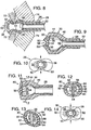
- mouthpiece 26 can be deformed from its closed position to a dispensing position, shown in Figs. 8-10 , when a force is applied to the regions of bite region 44 generally adjacent ends 40 of slit 38.
- This compressive force is applied along the axes of the lips, as indicated generally with arrows in Fig. 10 , and causes lips 50 to spread at least partially apart from each other to cause slit 38 to form an opening, also referred to as a hydraulic orifice, through which fluid may be passed.
- the term dispensing position broadly refers to any of the positions in which the lips are spread at least partially apart from each other so that the slit forms an opening through which fluid may be dispensed. It should be understood that the size of the opening formed by slit 38 will vary depending upon the amount of force applied by the user.
- mouthpiece 26 Once in a dispensing position, the user may draw fluid through the mouthpiece, much like the user would draw upon a drinking straw. As discussed, this is referred to as the normal operating condition for using mouthpiece 26 and any attached hydration system. When this force is removed, the resilient nature of mouthpiece 26, and more particularly, head 32 and lips 50 causes the mouthpiece to return to its closed, non-dispensing position.
- An example of a suitable material for mouthpiece 26 is fifty-five durometer silicone, although it is within the scope of the invention that other materials may be used as well, as long as they meet the operating criteria discussed herein.
- Mouthpiece 80 has the same components and subcomponents as the previously described mouthpiece 26.
- mouthpiece 80 includes a plurality of resilient supporting ribs 82 that extend from lips 50 to provide increased protection against leaks by biasing the lips to return to their closed position.
- a rib 82 extends from each lip 50, and more, particularly from side wall 56 of each lip along inner surface 52 of dispensing face 32. It should be understood, however, that it is within the scope of the invention that ribs 82 could alternatively extend along the outer surface of face 32.
- Each rib 82 extends from a respective one of the lips at a first position, and returns to the lip at a second position spaced-apart from the first.
- ribs 82 are bent or deformed from the resting position shown in Figs. 12 and 13 to a dispensing position shown in Fig. 14 .
- ribs 82 further bias the mouthpiece, and especially face 32 and lips 50 to return to the closed position.
- ribs 82 include ends 84 that extend from lips 50 as described above and taper to an intermediate region 86 of narrower cross-section than ends 84.
- intermediate region 86 which extends in a portion of face 32 that undergoes significant bending or deformation, minimizes the amount of additional force needed to deform mouthpiece 80 to its dispensing position, while still providing a continuous, curved support for lips 50.
- intermediate region 86 is substantially or completely coplanar with inner surface 52.
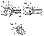
- FIGs. 15-17 another alternate embodiment of the invented mouthpiece is shown and indicated generally at 90.
- mouthpiece 90 has the same components, dimensions and properties as mouthpiece 26, including a neck 28 and a head 30 that includes a dispensing face 32 (with a pair of lips that define a normally closed slit 38), a bite region 44, a transition region 46, and a supply chamber 48 defined by the dispensing face and the bite region.
- the inner surface of face 32 is generally indicated at 92, and it can be seen that surface 92 has a convex cross-sectional configuration generally transverse to slit 38.
- the thickness of face 32 distal slit 38 is between approximately 0.15cm (0.06 inches) and approximately 0.36cm (0.14 inches), similar to the faces of the previously discussed mouthpieces.
- a thickness distal slit 38 of approximately 2.03cm (0.8 inches) has proven to perform particularly well.
- surface 92 extends from bite region 44 toward slit 38, it can be seen in Figs. 15 and 17 that face 32 increases in thickness and extends into the supply chamber until it forms a pair of lips 94 that define slit 38.
- the radius of curvature of surface 92 is approximately 1.91cm (0.75 inches), although it should be understood that larger or small radii of curvature may be acceptable as welL
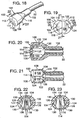
- mouthpiece 100 has outer dimensions that correspond with the previously disclosed embodiments, including a neck 102 and a head 104 with a dispensing face 106, bite region 108 and lip-receiving shoulder 110. Face 106 extends to an outer perimeter 112, where it is joined to a bite region 108, and includes a pair of opposed lips 114 that define a slit 116 (indicated in Fig. 19 ) extending therebetween. As shown in Fig. 19 , slit 116 is elongate and has a pair of ends 118 adjacent perimeter 112. Unless otherwise specified, mouthpiece 100 has the same elements and subelements as any of the above embodiments, including the shapes, properties and possible variations discussed with respect to the mouthpieces shown in Figs. 1-17 .
- bite region 108 extends from head 104 to form the internal surface, or side wall, 122 of a supply chamber 120, into which fluid is received prior to being dispensed from face 106.
- side wall 122 encircles the supply chamber and forms plural corners 124 distal slit 116.
- corners 124 define fold lines that extend away from face 106 generally transverse to slit 116.
- Side wall 122 may alternatively be described as including plural discontinuities because the otherwise smooth, or actuate, inner wall is broken by the apexes of the corners.
- side wall 122 includes regions 130 that have generally planar configurations and meet to form apexes 126 distal slit 116.
- abutting regions 130 are pivoted toward each other about apex 126.
- Regions 130 give side wall 122 a generally polygonal configuration in a plane parallel to perimeter 112, and as shown in Figs. 19 and 22 , generally resembles a hexagon. It should be understood, however, that there may still be some curvature to portions of side wall 120.
- a slight curvature proximate ends 118 of slit 116 promotes easier opening of slit 116 when a user bites upon bite region 104.
- Abutting regions 130 extend at an angle with respect to each other that is between approximately 80° and approximately 130°, preferably between approximately 90° and approximately 125°, and more preferably between approximately 100° and approximately 120°. Angles outside of this range are also within the scope of the present invention, however the above-discussed angular ranges are presently preferred.
- regions 130 extend at an angle of approximately 114° with respect to each other, with side wall 120 having a thickness at apex 126 of approximately 0.16 inches. This thickness is measured from the supply chamber outwardly to the closest point on the outer surface of the bite region.
- bite region 108 has a reduced thickness than the corresponding regions adjacent apex 126.
- This thinner, generally pointed configuration of the apexes 126, along which the corresponding fold lines extend, enables the mouthpiece to flex or pivot about the apex to the dispensing position when a user bites upon region 108.
- the mouthpiece deforms substantially by pivoting about the apex instead of by compressing a relatively thick, or even thickest, portion of the bite region. This enables the slit to create a hydraulic orifice with a larger area, without requiring the slit to be lengthened.
- the mouthpiece Upon removal of the deforming force, the mouthpiece is biased to spring back to its original, unstressed position in which slit 116 is closed and no fluid is dispensed therethrough.
- mouthpiece 100 Experiments using mouthpiece 100 have demonstrated that fluid may be dispensed from dispensing face 106 at a rate greater than 40 ml/sec, including flowrates of approximately 45 ml/sec, under the normal operating conditions discussed previously.
- lips 114 extend into supply chamber 120 beyond dispensing face 106. Furthermore, lips 114 include end walls 132 and side walls 134 that extend at an angle between face 106 and the corresponding end wall 132. End walls 132 and side walls 134 of lips 114 may include any of the configurations and shapes described above with respect to end walls 54 and side walls 56, including side walls that extend generally transverse to face 106, as shown in Fig. 23 . Side walls that extend at an angle of between approximately 30° and approximately 60° are currently preferred because they promote more laminar flow of the fluid as it is received within supply chamber 120 and dispensed through slit 116, however, the invented lips encompass any of the configurations of lips disclosed herein.
Landscapes
- Engineering & Computer Science (AREA)
- Mechanical Engineering (AREA)
- Containers And Packaging Bodies Having A Special Means To Remove Contents (AREA)
- Closures For Containers (AREA)
- Table Equipment (AREA)
- Devices For Dispensing Beverages (AREA)
- Infusion, Injection, And Reservoir Apparatuses (AREA)
- Table Devices Or Equipment (AREA)
Claims (22)
- Mundstück (26, 80, 90, 100), geeignet für ein persönliches Hydratations-System (10), aufweisend ein Fluid-Reservoir, von dem aus sich ein flexibler Schlauch (22) erstreckt, wobei das Mundstück umfasst:- einen Halsteil (28), der dafür angepasst ist, an ein Ende des Schlauchs (22) montiert zu werden; und- einen Kopf (30), der sich von dem Halsteil (28) aus erstreckt und dafür angepasst ist, in den Mund eines Benutzers aufgenommen zu werden, worin der Kopf (30) eine Abgabe-Stirnfläche (32, 106) mit einer Umfassung (34) und einer Mindest-Abmessung, die die Mindest-Entfernung zwischen einander gegenüber liegenden Punkten auf der Umfassung ist, einschließt, worin die Abgabe-Stirnfläche (32) ein Paar einander gegenüber liegender Lippen (50, 114) einschließt, die einen normalerweise geschlossenen Spalt (38) definieren, der sich zwischen diesen erstreckt, worin der Kopf weiter eine Biss-Region (44) einschließt, die sich von der Umfassung (34) allgemein in Richtung auf den Hals zu einer die Lippen aufnehmenden Schulter (46) erstreckt, wobei sich die Lippen aufnehmende Schulter (46) von der Biss-Region (44) zu dem Halsteil (28) erstreckt, worin die Abgabe-Stirnfläche (32) und die Biss-Region (44) gemeinsam eine Zuleitungs-Kammer (48, 120) definieren, und weiter worin ein Zusammendrücken der Biss-Region (44) entlang der Achsen von Lippen (50) derart, dass eine Zusammendrück-Kraft auf die Regionen der Biss-Region (44) aufgebracht wird, die Enden (40) des Spalts (38) benachbart ist, das Mundstück (26) von einer geschlossenen Position, in der sich die Lippen (50) in Kontakt miteinander unter Schließen des Spalts (38) erstrecken und verhindern, dass Fluid durch den Spalt abgegeben wird, in eine abgebende Position deformiert, in der die Lippen (50, 114) wenigstens teilweise voneinander gespreizt werden und so ermöglichen, dass Fluid durch den Spalt (38) abgegeben wird, dadurch gekennzeichnet, dass die Biss-Region (44) eine Länge aufweist, gemessen von der Umfassung zu der die Lippen aufnehmenden Schulter, die geringer ist als die genannte Mindest-Abmessung.
- Mundstück (26, 80, 90, 100) nach Anspruch 1, worin sich die Lippen (50, 114) von der Abgabe-Stirnfläche in die Zuleitungskammer (48, 120) erstrecken.
- Mundstück (80) nach irgendeinem der Ansprüche 1 bis 2, worin die Abgabe-Stirnfläche (32) ein Paar elastischer Rippen (82) einschließt, die sich von den Lippen (50) entlang der Abgabe-Stirnfläche erstrecken und so die Lippen (50) in der geschlossenen Position vorspannen.
- Mundstück nach Anspruch 3, worin die Abgabe-Stirnfläche (32) eine innere Oberfläche (52) einschließt, entlang der sich das Paar elastischer Rippen (82) von den Lippen erstreckt.
- Mundstück nach Anspruch 3 oder Anspruch 4, worin jede der Rippen (82) sich radial entlang der Stirnfläche (32) von einer ersten Position auf jeweils einer der Lippen (50) weg von der Lippe (50) erstreckt und zu der Lippe an einer zweiten Position zurückkehrt, die von der ersten Position entfernt ist.
- Mundstück nach Anspruch 4 oder Anspruch 5, worin jede der Rippen (82) Endregionen (84) einschließt, die der entsprechenden Lippe (50) benachbart sind, sowie einen Zwischenbereich (86), der allgemein zwischen den Endregionen (84) liegt, mit einem schmaleren Querschnitt als die Endregionen (84).
- Mundstück nach irgendeinem der Ansprüche 1 bis 6, worin die Biss-Region (44) eine Länge aufweist, gemessen in der Richtung der Fluid-Strömung, die geringer ist als 1,8 cm (0,7 in), und gegebenenfalls zwischen etwa 1,01 cm (0,4 in) und etwa 1,5 cm (0,6 in).
- Mundstück nach irgendeinem der Ansprüche 1 bis 7, worin die Biss-Region (44) eine Länge aufweist, gemessen in der Richtung eines Fluid-Stroms, die geringer ist als 80 % der Länge der Mindest-Abmessung.
- Mundstück nach irgendeinem der Ansprüche 1 bis 8, worin die Abgabe-Stirnfläche (32) eine konvexe innere Oberfläche (92) aufweist.
- Mundstück nach irgendeinem der Ansprüche 1 bis 9, worin die Dicke der Abgabe-Stirnfläche (32) distal von dem Spalt (36) geringer ist als die Dicke der Abgabe-Stirnfläche (32) in Nachbarschaft zu dem Spalt (36).
- Mundstück nach irgendeinem der Ansprüche 1 bis 10, worin der Spalt (38, 40, 116) in der Abgabe-Position eine Öffnung bildet, die so konfiguriert ist, dass sie Fluid von dem Mundstück mit einer Strömungsrate größer als 30 ml/s und gegebenenfalls größer als 40 ml/s abgibt, wenn das Mundstück im Mund eines Benutzers angeordnet wird, in die Abgabe-Position gebracht wird und daran von dem Benutzer gezogen wird.
- Mundstück nach irgendeinem der Ansprüche 1 bis 11, worin der Hals (28) eine Innenwandung aufweist, die einen Innendurchmesser definiert, und der Spalt (38, 40, 116) eine Länge aufweist, die wenigstens 150 % des Innendurchmessers des Halses (28) ist.
- Mundstück (100) nach irgendeinem der Ansprüche 1 bis 12, worin die Biss-Region (108) eine Innenfläche (122) einschließt, die die Zuleitungskammer (120) definiert, in die Fluid aufgenommen wird, bevor es durch die Abgabe-Stirnfläche (106) abgegeben wird, und weiter worin die Innenfläche (122) mehrere Ecken (124) einschließt, die sich entlang wenigstens einem Teil der Innenfläche (122) in einer Richtung erstrecken, die allgemein quer zu der Stirnfläche ist.
- Mundstück nach Anspruch 13, worin jede Ecke (124) eine Spitze (126) distal von dem Spalt (116) aufweist.
- Mundstück nach Anspruch 14, worin jede Ecke (124) weiter allgemein planare Regionen (130) in Nachbarschaft zu ihrer Spitze einschließt.
- Mundstück nach Anspruch 15, worin jede Spitze (126) dafür angepasst ist, eine Achse bereitzustellen, um die die planaren Regionen (130) auf einander zu gedreht werden, wenn das Mundstück in die abgebende Position deformiert wird.
- Mundstück nach irgendeinem der Ansprüche 1 bis 12, worin die Biss-Region (108) eine Innenfläche (122) einschließt, die die Zuleitungskammer (120) definiert, in die Fluid aufgenommen wird, bevor es durch die Abgabe-Stirnfläche abgegeben wird, und weiter worin die Innenfläche (122) mehrere allgemein planare Regionen (130) einschließt, die sich allgemein quer zu der Stirnfläche (106) erstrecken, und worin die planaren Regionen (130) an einer Spitze (126) vereinigt sind, die sich quer zu der Stirnfläche distal von dem Spalt (116) erstreckt und die Spitze (126) dafür angepasst ist, eine Achse bereitzustellen, um die die planaren Regionen (130) auf einander zu gedreht werden, wenn das Mundstück in die abgebende Position deformiert wird.
- Mundstück nach irgendeinem der Ansprüche 14 bis 17, worin die Dicke der Biss-Region (108) an jeder Spitze (126) geringer ist als die Dicke nahe jeder Spitze.
- Mundstück nach irgendeinem der Ansprüche 1 bis 18, worin die Abgabe-Stirnfläche (32, 106) integral mit der Biss-Region (44), der die Lippen aufnehmenden Schulter (46) und dem Halsteil (28) ist.
- Mundstück nach irgendeinem der Ansprüche 1 bis 18, worin ein Teil der Abgabe-Stirnfläche (32, 106), der die Umfassung definiert, integral mit der Biss-Region (44) und dem Halsteil (28) ist.
- Mundstück nach irgendeinem der Ansprüche 1 bis 20 in Kombination mit einem persönlichen Hydratations-System (10), worin das Hydratations-System ein Reservoir (12) umfasst, das dafür konfiguriert ist, einen Vorrat eines Fluids zu halten, und eine Ausstoßöffnung (18) einschließt, durch die das Fluid hindurch geführt werden kann und einen flexiblen Schlauch (22) mit einem ersten Ende (20), das mit der Ausstoßöffnung verbunden ist, und einem zweiten Ende (24), das mit dem Mundstück verbunden ist; und weiter worin bei Anordnen des Mundstücks im Mund eines Benutzers der Benutzer Fluid aus dem Reservoir durch den Schlauch zu dem Mundstück zur Abgabe in den Mund des Benutzers ziehen kann.
- Mundstück nach Anspruch 21, weiter einschließend eine Packung, die dafür angepasst ist, das Reservoir (12) aufzunehmen.
Applications Claiming Priority (7)
| Application Number | Priority Date | Filing Date | Title |
|---|---|---|---|
| US118196 | 1998-07-17 | ||
| US09/118,196 US6070767A (en) | 1998-07-17 | 1998-07-17 | Personal hydration system with an improved mouthpiece |
| PCT/US1998/014962 WO2000003945A1 (en) | 1998-07-17 | 1998-07-20 | Personal hydration system with an improved mouthpiece |
| WOPCT/US98/14962 | 1998-07-20 | ||
| US151493 | 1998-09-11 | ||
| US09/151,493 US6032831A (en) | 1998-07-17 | 1998-09-11 | Personal hydration system with an improved mouthpiece |
| PCT/US1999/016085 WO2000003946A1 (en) | 1998-07-17 | 1999-07-16 | Personal hydration system with an improved mouthpiece |
Publications (3)
| Publication Number | Publication Date |
|---|---|
| EP1017618A1 EP1017618A1 (de) | 2000-07-12 |
| EP1017618A4 EP1017618A4 (de) | 2001-10-17 |
| EP1017618B1 true EP1017618B1 (de) | 2008-10-22 |
Family
ID=26816072
Family Applications (1)
| Application Number | Title | Priority Date | Filing Date |
|---|---|---|---|
| EP99935615A Expired - Lifetime EP1017618B1 (de) | 1998-07-17 | 1999-07-16 | Persönliche trinkvorrichtung mit verbessertem mundstück |
Country Status (8)
| Country | Link |
|---|---|
| US (3) | US6070767A (de) |
| EP (1) | EP1017618B1 (de) |
| AT (1) | ATE411970T1 (de) |
| AU (2) | AU8500098A (de) |
| CA (1) | CA2302210C (de) |
| DE (1) | DE69939766D1 (de) |
| ES (1) | ES2317700T3 (de) |
| WO (2) | WO2000003945A1 (de) |
Cited By (2)
| Publication number | Priority date | Publication date | Assignee | Title |
|---|---|---|---|---|
| WO2010028413A2 (de) | 2008-09-09 | 2010-03-18 | Florian Wiplinger | Vorrichtung zur aufnahme von flüssigkeit |
| WO2012027768A1 (de) | 2010-09-02 | 2012-03-08 | Florian Wiplinger | Vorrichtung zur aufnahme von flüssigkeit |
Families Citing this family (129)
| Publication number | Priority date | Publication date | Assignee | Title |
|---|---|---|---|---|
| US6070767A (en) | 1998-07-17 | 2000-06-06 | Camelbak Products, Inc. | Personal hydration system with an improved mouthpiece |
| ES1044082Y (es) * | 1999-08-05 | 2000-08-16 | Casa Artiach S A | Valvula perfeccionada para colchonetas. |
| US6279772B1 (en) * | 1999-08-11 | 2001-08-28 | Ronald Lee Bowman | Manually actuable fluid dispensing unit and process |
| US6273128B1 (en) * | 1999-08-11 | 2001-08-14 | Joseph R. Paczonay | Apparatus for controlling the flow of fluid |
| US6854888B1 (en) * | 2000-01-28 | 2005-02-15 | Dennis B. Brown | Multispout flask with pump |
| AU8051201A (en) * | 2000-07-10 | 2002-02-05 | Camelbak Products Inc | Hydration system with improved fluid reservoir |
| GB2382978B (en) * | 2000-09-01 | 2004-06-30 | Jeff Skillern | Hydration pouch with integral thermal medium |
| IL145424A (en) | 2000-09-14 | 2004-08-31 | Source Vagabond Systems Ltd | Mouthpiece for drinking |
| AU1302902A (en) * | 2000-09-28 | 2002-04-08 | Shanta Balakumar | Infant's feeding cup |
| EP1222873A1 (de) * | 2001-01-16 | 2002-07-17 | SIGG Switzerland AG | Mundstück für Trinkleitung |
| US6302303B1 (en) * | 2001-02-26 | 2001-10-16 | Robert Reynolds | Discrete liquid transport and discharge apparatus and method |
| US6264166B1 (en) | 2001-03-05 | 2001-07-24 | Mark A. Bowland | Hands-free activating valve for use with liquid containers |
| WO2002070399A1 (en) * | 2001-03-06 | 2002-09-12 | Texas Research International, Inc. | A chemically and biologically resistant hydration system |
| TW472782U (en) * | 2001-05-11 | 2002-01-11 | Universal Trim Supply Co Ltd | Sturcture of integrally-formed sucker with soft and hard plastic material |
| US6409048B1 (en) | 2001-05-15 | 2002-06-25 | Gregory L. Belzeski | Pressurizing device for a personal hydration system |
| US20040060598A1 (en) * | 2001-06-13 | 2004-04-01 | Hal Danby | Vacuum demand flow valve |
| US20020189685A1 (en) * | 2001-06-13 | 2002-12-19 | Danby Hal C. | Vacuum demand flow valve |
| US6554023B2 (en) * | 2001-06-13 | 2003-04-29 | Baxter International Inc. | Vacuum demand flow valve |
| US6550493B2 (en) | 2001-06-13 | 2003-04-22 | Baxter International Inc. | Vacuum demand valve |
| USD493866S1 (en) | 2001-06-13 | 2004-08-03 | Baxter Intl. Inc | Valve |
| US6651694B1 (en) * | 2001-07-17 | 2003-11-25 | The Protector Corporation | Insulating cover and method for liquid supply tube |
| US20040089301A1 (en) | 2001-10-09 | 2004-05-13 | Robert Choi | Personal hydration system with component connectivity |
| US6722533B2 (en) | 2002-02-26 | 2004-04-20 | Jeff Skillern | Hydration pouch with detachable hose |
| US7311231B2 (en) * | 2002-02-26 | 2007-12-25 | Blackhawk Industries Product Group Unlimited Llc | Disposable pouch hydration system |
| US6863261B2 (en) * | 2002-03-12 | 2005-03-08 | Baxter International Inc. | Valve stop |
| US20030218076A1 (en) * | 2002-03-29 | 2003-11-27 | Donald Farnsworth | Novelty pump straw with combined display area and prize delivery system |
| US6892915B2 (en) * | 2002-04-15 | 2005-05-17 | Camelbak Products, Llc | Pack frame assembly and hydration systems incorporating the same |
| US20040000570A1 (en) * | 2002-06-27 | 2004-01-01 | Forsman Barley A. | Strap management system, packs and hydration systems incorporating the same |
| AU2002950725A0 (en) * | 2002-08-12 | 2002-09-12 | Craig Dean Chamulko | Tamper-proof cup |
| US20040045980A1 (en) * | 2002-09-06 | 2004-03-11 | Robins Duncan G. | Personal hydration system with pump |
| US20040065703A1 (en) * | 2002-10-07 | 2004-04-08 | Bellucci Randy A. | Athletic hydration pack |
| US6851275B2 (en) * | 2002-10-10 | 2005-02-08 | Stokely-Van Camp, Inc. | In-car hydration systems |
| US6755047B2 (en) | 2002-10-10 | 2004-06-29 | Stokley-Van Camp, Inc. | In-car hydration systems |
| US6745594B2 (en) | 2002-10-10 | 2004-06-08 | Stokley-Van Camp, Inc. | In-car hydration systems |
| AU2003297690A1 (en) * | 2002-12-03 | 2004-06-23 | Silver Eagle Outfitters Llc | Personal hydration and cooling system |
| USD499793S1 (en) | 2003-03-17 | 2004-12-14 | Baxter International Inc. | Valve |
| USD507631S1 (en) | 2003-03-17 | 2005-07-19 | Baxter International Inc. | Valve |
| US20060144955A1 (en) * | 2003-03-27 | 2006-07-06 | Donald Farnsworth | Novelty pump straw with combined display area and prize delivery system |
| US20040217123A1 (en) * | 2003-04-09 | 2004-11-04 | Shih-Sheng Yang | Nozzle and manufacturing method thereof |
| USD505540S1 (en) * | 2003-04-28 | 2005-05-31 | Chien-Ping Lien | Water bag |
| WO2004100708A2 (en) * | 2003-05-08 | 2004-11-25 | Fiskars Brands, Inc. | Personal hydration system |
| GB2405138A (en) * | 2003-07-24 | 2005-02-23 | Bw Technologies Ltd | Valves for portable flexible drinking vessels |
| US7201299B2 (en) * | 2003-08-13 | 2007-04-10 | Camelbak Products, Llc | Waist-mounted hydration system |
| US7014077B2 (en) * | 2003-08-13 | 2006-03-21 | Nalge Nunc International | Portable container |
| US6840100B1 (en) | 2003-09-04 | 2005-01-11 | Richard A. Wotiz | Liquid level indicator |
| US7204382B2 (en) * | 2003-09-15 | 2007-04-17 | Thomas Edward Cezeaux | Drinking tube and cap assembly |
| USD507447S1 (en) | 2003-10-06 | 2005-07-19 | Joseph C. Moore | Bite valve |
| US8127789B2 (en) * | 2003-10-30 | 2012-03-06 | ARK Therapeutic Services, Inc. | Fluid retaining apparatus with ball valve |
| WO2005052366A2 (en) | 2003-11-20 | 2005-06-09 | The Henry M. Jackson Foundation For The Advancement Of Military Medicine, Inc. | Portable hand pump for evacuation of fluids |
| CN100464664C (zh) * | 2004-03-19 | 2009-03-04 | 杨士圣 | 具有大开口状态的软式吸嘴制造方法 |
| US7267245B2 (en) * | 2004-04-30 | 2007-09-11 | Shih-Sheng Yang | Bite valve |
| US20050242204A1 (en) * | 2004-04-30 | 2005-11-03 | Ness Richard A | Leak-resistant drinking systems |
| USD539028S1 (en) | 2004-05-06 | 2007-03-27 | Fiskars Brands, Inc. | Personal hydration system reservoir |
| US7819293B1 (en) | 2004-05-19 | 2010-10-26 | O'connell Thomas P | Replenishable drinking vessel |
| EP1600139A1 (de) * | 2004-05-25 | 2005-11-30 | Optical System & Research for Industry and Science Osyris | Luftdicht verschlossener Behälter zur Aufbewahrung einer flüssigen Substanz, insbesondere einer medizinischen Substanz, und Verfahren zur aseptischen Abfüllung dieses Behälters |
| US20070181616A9 (en) * | 2004-08-10 | 2007-08-09 | Michael Horito | Bite valve retainer |
| US8337475B2 (en) | 2004-10-12 | 2012-12-25 | C. R. Bard, Inc. | Corporeal drainage system |
| US7631672B2 (en) * | 2004-11-30 | 2009-12-15 | Christerson Abraham Spencer | Portable hydration system with resupply system |
| USD538030S1 (en) | 2005-01-27 | 2007-03-13 | Fiskars Brands, Inc. | Personal hydration system reservoir |
| US7600656B2 (en) | 2005-01-27 | 2009-10-13 | Fiskars Brands, Inc. | Personal hydration system |
| DE102005004256A1 (de) * | 2005-01-28 | 2006-08-10 | Grünenthal GmbH | Trinkhalm mit einer Versteifung |
| US7533783B2 (en) | 2005-04-11 | 2009-05-19 | Camelbak Products, Llc | Drink bottles with bite-actuated mouthpieces |
| US20060243765A1 (en) * | 2005-04-27 | 2006-11-02 | Valeriana Peter V | Pressurized personal hydration system and kit |
| WO2006122368A1 (en) * | 2005-05-19 | 2006-11-23 | Calfarme (Singapore) Pte Ltd | Valve structures for liquid dispensing |
| US20070075094A1 (en) * | 2005-08-09 | 2007-04-05 | Brown Dennis B | Articulated bite valve |
| USD547607S1 (en) | 2005-08-09 | 2007-07-31 | Camelbak Products, Llc | Drink bottle cap |
| US20070034634A1 (en) * | 2005-08-09 | 2007-02-15 | Brown Dennis B | Hydration system with articulating port structure |
| USD547606S1 (en) | 2005-08-09 | 2007-07-31 | Camelbak Products, Llc | Bite actuated mouthpiece |
| US8177772B2 (en) | 2005-09-26 | 2012-05-15 | C. R. Bard, Inc. | Catheter connection systems |
| US20070108238A1 (en) * | 2005-11-15 | 2007-05-17 | Andrew Kirker | Personal beverage supply assembly |
| US20070267425A1 (en) * | 2006-01-27 | 2007-11-22 | Yoram Gill | Dispenser device |
| US20070280565A1 (en) * | 2006-06-02 | 2007-12-06 | Hydrapak, Inc. | Reservoir system and method |
| EP2049875B1 (de) * | 2006-08-07 | 2020-09-09 | MVM Pack-Holding AG | Dosierelement mit einem schlitzförmigen auslass |
| USD581152S1 (en) | 2007-03-19 | 2008-11-25 | Fiskars Brands, Inc. | Personal hydration system reservoir |
| US20080277433A1 (en) * | 2007-03-19 | 2008-11-13 | Fiskars Brands, Inc. | Modular personal hydration and storage system |
| US20080236574A1 (en) * | 2007-04-02 | 2008-10-02 | Ann Marx | Mouthpiece for preventing formation of perioral rhytids |
| US20080047857A1 (en) * | 2007-08-13 | 2008-02-28 | Roger Cleveland Golf Co., Inc. | Golf bag |
| FR2928357B1 (fr) * | 2008-03-06 | 2015-05-15 | Airlessystems | Obturateur d'organe de distribution de produit fluide. |
| US8276785B1 (en) | 2008-04-19 | 2012-10-02 | D. Wheatley Enterprise, Inc. | NBC/CBRNE personal hydration system |
| US20100004629A1 (en) * | 2008-07-03 | 2010-01-07 | Drip Drop Solutions, Inc. | Apparatus and methods to implement a versatile liquid storage and delivery mechanism |
| US20100123019A1 (en) * | 2008-11-14 | 2010-05-20 | Hydroback Hydration Systems, Llc | Bottle adaptor for personal hydration system |
| US8191727B2 (en) | 2009-01-21 | 2012-06-05 | Camelbak Products, Llc | Drink containers |
| WO2010132377A1 (en) * | 2009-05-11 | 2010-11-18 | Heetsmonete, Llc | Portable pet bathing device |
| GB0916318D0 (en) * | 2009-09-17 | 2009-10-28 | Samson Ilan Z | Spout for a spill-proof beverage container |
| US8177097B2 (en) | 2009-12-08 | 2012-05-15 | Camelbak Products, Llc | Personal hydration systems, dryer mechanisms for use with personal hydration systems, and methods of drying personal hydration system reservoirs |
| US9624089B1 (en) | 2010-11-11 | 2017-04-18 | Arctic Innovations, Llc | Cold weather hydration systems, devices, components and methods |
| AU2012294882B2 (en) | 2011-08-09 | 2016-07-21 | Hollister Incorporated | Ostomy appliance |
| US9833352B2 (en) | 2011-08-23 | 2017-12-05 | Mayo Foundation For Medical Education And Research | Ostomy devices |
| US9149109B2 (en) | 2012-01-09 | 2015-10-06 | Rocket44 LLC | Two reservoir fluid delivery system |
| USD667672S1 (en) * | 2012-01-27 | 2012-09-25 | Jennifer Royer | Straw with wide end |
| US8851324B2 (en) | 2012-02-08 | 2014-10-07 | Sean Patrick O'Sullivan | Drinking cup with a straw connected to the bottom of the cup |
| US10053356B2 (en) | 2012-04-24 | 2018-08-21 | Rx Hydration, Inc. | Systems, kits and methods for hands free, on demand, oral delivery of materials |
| US9828982B1 (en) | 2014-06-24 | 2017-11-28 | Sporting Innovations, Llc | Electric pump and delivery tube for personal hydration system |
| US9609969B1 (en) * | 2014-07-23 | 2017-04-04 | Acorn Bay | Deformable elastomeric valve and valve assembly |
| US10315816B2 (en) | 2015-09-29 | 2019-06-11 | Samsonite Ip Holdings S.A R.L. | Hydration reservoir |
| US20170121069A1 (en) * | 2015-10-20 | 2017-05-04 | Sagan Industries Llc | Quick connect mouthpiece for liquid container |
| USD802293S1 (en) | 2016-01-13 | 2017-11-14 | Dgm Creations Llc | Hydration sleeve |
| WO2017124015A1 (en) | 2016-01-14 | 2017-07-20 | Dgm Creations Llc | Hydration sleeve and bladder and related systems and methods |
| USD830050S1 (en) | 2016-05-23 | 2018-10-09 | Camelbak Products, Llc | Hydration system |
| US20180038534A1 (en) | 2016-07-18 | 2018-02-08 | Rainmaker Solutions, Inc. | Mouthpiece assembly |
| WO2018017365A1 (en) | 2016-07-18 | 2018-01-25 | Merit Medical Systems, Inc. | Inflatable radial artery compression device |
| USD809285S1 (en) | 2016-08-29 | 2018-02-06 | Dgm Creations Llc | Disposable hydration bladder |
| USD802294S1 (en) | 2016-08-29 | 2017-11-14 | Dgm Creations Llc | Hydration sleeve |
| USD822952S1 (en) | 2016-08-29 | 2018-07-17 | Dgm Creations Llc | Garment with integrated hydration system |
| US10179726B2 (en) | 2016-09-30 | 2019-01-15 | Matthew J Steele | Wirelessly-activated and controlled portable hydration systems, devices, components and methods |
| US10492552B2 (en) * | 2016-11-17 | 2019-12-03 | Rainmaker Solutions, Inc. | Hydration and audio system |
| US20180193676A1 (en) * | 2016-11-17 | 2018-07-12 | Rainmaker Solutions, Inc. | Hydration and air cooling system |
| US10578219B1 (en) | 2017-04-10 | 2020-03-03 | William August Holmes | Breathe and drink and safely swallow bite valve |
| US11406525B2 (en) | 2017-11-09 | 2022-08-09 | 11 Health And Technologies Limited | Ostomy monitoring system and method |
| US10357073B1 (en) * | 2018-01-19 | 2019-07-23 | Rainmaker Solutions, Inc. | Headset and components thereof for fluid delivery system |
| US11470904B2 (en) * | 2018-01-19 | 2022-10-18 | Rainmaker Solutions, Inc. | Hydration system and components thereof |
| US12041998B2 (en) * | 2018-01-19 | 2024-07-23 | Rainmaker Solutions, Inc. | Hydration system and components thereof |
| US11427119B2 (en) * | 2018-03-23 | 2022-08-30 | O'dochartaigh, Llc | Fuel tank-mounted beverage container for a motorcycle |
| USD871836S1 (en) | 2018-05-31 | 2020-01-07 | Camelbak Products, Llc | Bite-actuated mouthpiece |
| US11345523B2 (en) | 2018-05-31 | 2022-05-31 | Camelbak Products, Llc | Bite-actuated mouthpieces and drink vessels including bite-actuated mouthpieces |
| USD862985S1 (en) | 2018-05-31 | 2019-10-15 | Camelbak Products, Llc | Beverage container |
| USD901238S1 (en) | 2018-05-31 | 2020-11-10 | Camelbak Products, Llc | Bite-actuated mouthpiece |
| US10358270B1 (en) | 2018-05-31 | 2019-07-23 | Camelbak Products, Llc | Closure assemblies and drink containers including the same |
| USD864658S1 (en) | 2018-05-31 | 2019-10-29 | Camelbak Products, Llc | Beverage container closure |
| USD881639S1 (en) | 2018-06-19 | 2020-04-21 | Camelbak Products, Llc | Beverage container closure |
| US10532862B2 (en) | 2018-06-19 | 2020-01-14 | Camelbak Products, Llc | Closure assemblies with distinct dispensing modes and drink containers including the same |
| USD893514S1 (en) | 2018-11-08 | 2020-08-18 | 11 Health And Technologies Limited | Display screen or portion thereof with graphical user interface |
| US10421655B1 (en) | 2019-05-17 | 2019-09-24 | Arapaho Technologies Inc. | Portable hydration system |
| US11511916B1 (en) * | 2020-01-29 | 2022-11-29 | Brandon Bernardo | Top closure assembly and drinking bottles including the same |
| CN116113373A (zh) | 2020-08-13 | 2023-05-12 | 美国医疗设备有限公司 | 具有束紧腕带的可充气桡动脉压迫装置和使用方法 |
| USD1035823S1 (en) * | 2020-10-01 | 2024-07-16 | Samsonite Ip Holdings S.A R.L. | Hydration reservoir |
| AU2021361238A1 (en) | 2020-10-15 | 2023-05-25 | Convatec Technologies Inc. | Ostomy systems and methods |
| US12426864B2 (en) | 2021-06-18 | 2025-09-30 | Merit Medical Systems, Inc. | Hemostasis devices and methods of use |
| US20230061489A1 (en) * | 2021-08-25 | 2023-03-02 | Milmar Higgins | Lip-pucker avoiding drinking straw |
Family Cites Families (112)
| Publication number | Priority date | Publication date | Assignee | Title |
|---|---|---|---|---|
| US357272A (en) * | 1887-02-08 | donayin | ||
| US33343A (en) * | 1861-09-24 | Improvement in knapsacks | ||
| US274447A (en) * | 1883-03-20 | William-kentish | ||
| US1326966A (en) * | 1920-01-06 | Respirator-valve | ||
| US259151A (en) * | 1882-06-06 | Eobeet holbon | ||
| US581767A (en) * | 1897-05-04 | Bicycle | ||
| GB190319546A (en) * | 1903-09-10 | 1903-11-05 | Max Rothenbuecher | An Improved Combination Article of Clothing and Rucksack, Knapsack or the like. |
| US964620A (en) * | 1909-07-23 | 1910-07-19 | Martha W Dana | Watch-pocket. |
| US1272519A (en) * | 1917-10-01 | 1918-07-16 | Mark A Piper | Trousers-belt. |
| US1404163A (en) * | 1918-11-21 | 1922-01-17 | Arthur E Pim | Device for use in picking fruit |
| US1426024A (en) * | 1921-03-09 | 1922-08-15 | John A Thureson | Hunting and fishing jacket |
| US1576430A (en) * | 1923-03-09 | 1926-03-09 | Otto Q Beckwith | Screen separator |
| US1637635A (en) * | 1926-11-08 | 1927-08-02 | Marshal D Corley | Lubricant-transporting receptacle |
| GB323451A (en) * | 1929-06-11 | 1930-01-02 | Sverre Young | Improvements in knapsacks |
| US1889963A (en) * | 1930-10-29 | 1932-12-06 | American Crayon Co | Vial |
| US2013358A (en) * | 1933-09-15 | 1935-09-03 | William B Osborne | Knapsack water bag |
| CH180216A (de) * | 1935-03-20 | 1935-10-15 | Hoher Lussi Heinrich | Anhängetasche. |
| US2095351A (en) * | 1936-06-11 | 1937-10-12 | William R Van Winkle | Painter's equipment |
| US2144755A (en) * | 1937-01-11 | 1939-01-24 | Eugene L Alexander | Closure device |
| DE693272C (de) * | 1938-05-21 | 1940-07-05 | Ernst Weber | Rucksack |
| US2219604A (en) * | 1939-11-20 | 1940-10-29 | George C Trotter | Dispensing device |
| US2320906A (en) * | 1941-11-05 | 1943-06-01 | Janet M Bales | Flush tank silencer |
| US2328095A (en) * | 1941-11-14 | 1943-08-31 | Mary C Phillips | Battery holder |
| US2380372A (en) * | 1942-09-28 | 1945-07-31 | Edward D Andrews | Portable container for compressed gases |
| US2500363A (en) * | 1946-03-11 | 1950-03-14 | Scovill Manufacturing Co | Container and closure means therefor |
| US2468915A (en) * | 1946-08-13 | 1949-05-03 | Tobias Kotzin | Patch pocket and method of making same |
| US2485442A (en) * | 1946-09-03 | 1949-10-18 | Halliday William | Hunting garment |
| FR1002897A (fr) * | 1949-12-21 | 1952-03-11 | Sac à dos perfectionné | |
| US2620479A (en) * | 1951-06-25 | 1952-12-09 | Lamb G Buck | Sportsman's garment |
| US2738907A (en) * | 1952-12-09 | 1956-03-20 | Lacher Seline Inc | Self-closing cap for collapsible tubes and the like |
| US2802608A (en) * | 1954-10-18 | 1957-08-13 | Joseph A Hull | Sealed valve dispensing device |
| US2792149A (en) * | 1954-10-28 | 1957-05-14 | Joseph M Lutz | Collapsible capless tube for toothpaste or the like |
| US2755480A (en) * | 1955-03-10 | 1956-07-24 | Utica Duxbak Corp | Hunting vest |
| US2954738A (en) * | 1957-11-08 | 1960-10-04 | Honeywell Regulator Co | Diaphragm pump |
| US2999499A (en) * | 1958-07-11 | 1961-09-12 | Cutter Lab | Flexible check valve |
| US3067787A (en) * | 1959-05-12 | 1962-12-11 | Norton Salk | Dispensing container |
| US3148624A (en) * | 1961-06-21 | 1964-09-15 | Alan W Baldwin | Hydraulic pump |
| US3165241A (en) * | 1963-01-25 | 1965-01-12 | Irene V M Curry | Feeder for invalids |
| US3199787A (en) * | 1963-08-26 | 1965-08-10 | Trico Products Corp | Windshield washer system |
| GB1006765A (en) * | 1964-05-25 | 1965-10-06 | Simpson Ltd S | Improvements connected with the waist bands of trousers |
| DE6806118U (de) * | 1968-11-08 | 1969-04-17 | Asf Gleitverschluss Gmbh | Aus einer kunststoffolie gebildeter beutel |
| US3822720A (en) * | 1971-03-04 | 1974-07-09 | Noyce R | Flow control assembly |
| US3819151A (en) * | 1972-09-22 | 1974-06-25 | C Kish | Flexible valve |
| US3796245A (en) * | 1973-11-21 | 1974-03-12 | O Wildensteiner | Drip meters |
| IL49974A (en) * | 1976-07-05 | 1978-08-31 | Yeda Res & Dev | Water bag |
| US4090650A (en) * | 1976-07-26 | 1978-05-23 | Gotta Harold J | Canteen with a straw |
| DE2644806B2 (de) * | 1976-10-05 | 1979-04-05 | Draegerwerk Ag, 2400 Luebeck | Atemschutzgerät mit Kreislauf der Atemluft |
| US4095812A (en) * | 1977-01-05 | 1978-06-20 | Rowe V Lopez | Bicycle drinking apparatus |
| US4089447A (en) * | 1977-07-05 | 1978-05-16 | Hans Wano Achmeteli | Back pack device |
| US4159790A (en) * | 1977-12-19 | 1979-07-03 | Bailey Vincent R | Dispensing container |
| US4148420A (en) * | 1978-01-30 | 1979-04-10 | Scale Models Unlimited | Self-sealing caps for squeeze-type containers |
| US4189075A (en) * | 1978-02-21 | 1980-02-19 | Hall John O | Packframe-canteen |
| US4139130A (en) * | 1978-03-06 | 1979-02-13 | Glusker Peter D | Canteen belt |
| US4153092A (en) * | 1978-05-03 | 1979-05-08 | Haslam Beverly J | Convertible handbag |
| US4265381A (en) * | 1978-08-28 | 1981-05-05 | Muscatell Steven C | Beverage and liquified food belt |
| US4274566A (en) * | 1979-05-14 | 1981-06-23 | Rowe V Lopez | Vehicle drinking apparatus |
| US4449654A (en) * | 1980-12-18 | 1984-05-22 | Cappis Lona P | Belt supported backpack |
| US4420097A (en) * | 1981-01-15 | 1983-12-13 | Motsenbocker Gregg A | Portable liquid dispenser with carrying case |
| DE3268026D1 (en) * | 1981-08-14 | 1986-01-30 | Ronald Modig | Holder for liquids |
| US4345704A (en) * | 1981-09-02 | 1982-08-24 | Cannondale Corporation | Bottle mount and bottle for bicycles |
| US4469097A (en) * | 1982-05-25 | 1984-09-04 | Kelman Charles D | Medical breathing apparatus |
| US4526298A (en) * | 1983-02-28 | 1985-07-02 | Cardiosearch, Inc. | Sport hydration system |
| US4541117A (en) * | 1983-07-28 | 1985-09-10 | Martin I. Davis | Sealing closure for a flexible container |
| US4629098A (en) * | 1984-10-15 | 1986-12-16 | Eger Douglas R | Portable liquid dispenser |
| US4617685A (en) * | 1985-04-08 | 1986-10-21 | S. G. D' Or Industries, Inc. | Ornamental belt |
| US4739905A (en) * | 1985-06-24 | 1988-04-26 | Nelson Steve R | Beverage dispensing device |
| US5143266A (en) * | 1986-01-10 | 1992-09-01 | Butler Creek Corporation | Harness |
| FR2597551B1 (fr) * | 1986-04-16 | 1993-11-12 | Alpha Systemes | Pompe distributrice jetable pour des produits liquides ou pateux |
| US4739913A (en) * | 1986-04-24 | 1988-04-26 | Michael C. Moore | Backpack type carrier for portable oxygen dispensers |
| US4758099A (en) * | 1987-01-29 | 1988-07-19 | Kcl Corporation | Flexible container having resealable closure |
| US4852781A (en) * | 1987-11-17 | 1989-08-01 | Shurnick Carl W | Runner's portable fluid supply container |
| US4948023A (en) * | 1987-12-07 | 1990-08-14 | Tripp Gordon R | Fluid storing and supply means |
| US4941598A (en) * | 1988-11-08 | 1990-07-17 | Ortho Pharmaceutical Corporation | Dosing cap |
| US5115947A (en) * | 1989-05-16 | 1992-05-26 | D. B. Smith & Co., Inc. | Collapsible water tank |
| US5060833A (en) * | 1989-08-14 | 1991-10-29 | Fastrak Systems, Inc. | Camel back |
| US5085349A (en) * | 1990-02-08 | 1992-02-04 | Fawcett Roger R | Resilient valve and dispensing system for bicyclists |
| US5062591A (en) * | 1990-02-12 | 1991-11-05 | Bikestream, Inc. | Pressurized potable beverage drinking system |
| US5104016A (en) * | 1990-02-12 | 1992-04-14 | Bikestream, Inc. | Pressurized potable beverage drinking system |
| US5152442A (en) * | 1990-09-17 | 1992-10-06 | Gallagher Richard N | Cartridge clip case |
| US5114059A (en) * | 1990-11-30 | 1992-05-19 | Ultimate Direction, Inc. | Universally adjustable, frameless backpack |
| USD337274S (en) | 1990-12-07 | 1993-07-13 | Ultimate Direction, Inc. | Combined water bottle and cap |
| USD337273S (en) | 1990-12-07 | 1993-07-13 | Ultimate Direction, Inc. | Combined water bottle and cap |
| US5215231A (en) * | 1991-04-15 | 1993-06-01 | Paczonay Joseph R | Water supply apparatus for bicycle |
| US5142702A (en) * | 1991-04-25 | 1992-09-01 | Piloian Gladys G | Upper body ostomy garment |
| US5152443A (en) * | 1991-07-03 | 1992-10-06 | Michael Hagan | Utility belt |
| US5839614A (en) * | 1991-12-06 | 1998-11-24 | Aptar Group, Inc. | Dispensing package |
| US5301858A (en) * | 1992-03-24 | 1994-04-12 | Hollander Douglas S | Combination water bottle |
| US5228609A (en) * | 1992-08-17 | 1993-07-20 | Bianchi International | Fannypack including an improved conformal waistband and lumbar pad |
| FR2696915B1 (fr) * | 1992-10-16 | 1994-12-09 | Rossignol Sa | Sac à dos. |
| US5282557A (en) * | 1992-11-06 | 1994-02-01 | Mccook Joe R | Liquid carrying harness |
| US5288150A (en) * | 1993-01-11 | 1994-02-22 | Jodi Bearman | Tote-bag with secondary access opening for removing debris |
| US5353975A (en) * | 1993-04-06 | 1994-10-11 | Michael Libertucci | Carrier for a portable stereo unit |
| DE4406162A1 (de) * | 1994-02-25 | 1995-08-31 | Wolfgang Linneweber | Selbstschließender Verschluß |
| GB2279130A (en) * | 1993-06-03 | 1994-12-21 | Duckhouse Geoffrey Charles | Valve for delivering fluids |
| US5407112A (en) * | 1993-06-21 | 1995-04-18 | Christodoulou; Thomas N. | Convertible backpack |
| US5497923A (en) * | 1993-08-09 | 1996-03-12 | Pearson; David P. | Suspender supported belt |
| US5427290A (en) * | 1994-01-10 | 1995-06-27 | Ultimate Direction, Inc. | Water pouch backpack |
| US5431308A (en) * | 1994-07-18 | 1995-07-11 | Tchen; Jian P. | Apparatus for storing and dispensing fluids for use by an athlete |
| US5725139A (en) * | 1994-08-15 | 1998-03-10 | Mountainsmith, Inc. | Backpack with adjustments for body size |
| US5586703A (en) * | 1995-05-26 | 1996-12-24 | Radar; Elizabeth | Dual field pack |
| US5566869A (en) * | 1995-06-26 | 1996-10-22 | Katz; Adam J. | Arm supported drinking container |
| US5816457A (en) * | 1995-08-11 | 1998-10-06 | Bianchi International | Hydration system |
| US5730336A (en) * | 1996-01-02 | 1998-03-24 | Cascade Designs, Inc. | Dispensing valve for a flexible liquid container |
| USD396630S (en) | 1996-03-07 | 1998-08-04 | Cascade Designs, Inc. | Collapsible bottle |
| US5601207A (en) * | 1996-03-13 | 1997-02-11 | Paczonay; Joseph R. | Bite valve having a plurality of slits |
| US5791510A (en) * | 1996-03-13 | 1998-08-11 | Paczonay; Joseph R. | Self sealing bite valve |
| US5755368A (en) * | 1996-06-13 | 1998-05-26 | Bekkedahl; James | Liquid dispensing apparatus for bicyclists and skaters |
| US5727720A (en) * | 1996-08-09 | 1998-03-17 | Ultimate Direction, Inc. | Modular hip-supported pack with bilateral articulation |
| USD398776S (en) | 1996-08-14 | 1998-09-29 | Fastrak Systems, Inc. | Pack with pocket |
| US5803333A (en) * | 1996-08-14 | 1998-09-08 | Fastrak Systems, Inc. | Pack with easy-access pocket |
| US5727714A (en) * | 1996-08-27 | 1998-03-17 | Fastrak Systems, Inc. | Personal hydration device with improved exit valve |
| US6070767A (en) | 1998-07-17 | 2000-06-06 | Camelbak Products, Inc. | Personal hydration system with an improved mouthpiece |
-
1998
- 1998-07-17 US US09/118,196 patent/US6070767A/en not_active Expired - Lifetime
- 1998-07-20 WO PCT/US1998/014962 patent/WO2000003945A1/en not_active Ceased
- 1998-07-20 AU AU85000/98A patent/AU8500098A/en not_active Abandoned
- 1998-09-11 US US09/151,493 patent/US6032831A/en not_active Expired - Lifetime
-
1999
- 1999-07-16 DE DE69939766T patent/DE69939766D1/de not_active Expired - Lifetime
- 1999-07-16 AU AU51058/99A patent/AU743809B2/en not_active Expired
- 1999-07-16 AT AT99935615T patent/ATE411970T1/de not_active IP Right Cessation
- 1999-07-16 CA CA002302210A patent/CA2302210C/en not_active Expired - Lifetime
- 1999-07-16 EP EP99935615A patent/EP1017618B1/de not_active Expired - Lifetime
- 1999-07-16 ES ES99935615T patent/ES2317700T3/es not_active Expired - Lifetime
- 1999-07-16 WO PCT/US1999/016085 patent/WO2000003946A1/en not_active Ceased
-
2000
- 2000-03-06 US US09/519,302 patent/US6364168B1/en not_active Expired - Lifetime
Cited By (2)
| Publication number | Priority date | Publication date | Assignee | Title |
|---|---|---|---|---|
| WO2010028413A2 (de) | 2008-09-09 | 2010-03-18 | Florian Wiplinger | Vorrichtung zur aufnahme von flüssigkeit |
| WO2012027768A1 (de) | 2010-09-02 | 2012-03-08 | Florian Wiplinger | Vorrichtung zur aufnahme von flüssigkeit |
Also Published As
| Publication number | Publication date |
|---|---|
| EP1017618A1 (de) | 2000-07-12 |
| WO2000003945A1 (en) | 2000-01-27 |
| EP1017618A4 (de) | 2001-10-17 |
| US6364168B1 (en) | 2002-04-02 |
| AU743809B2 (en) | 2002-02-07 |
| CA2302210C (en) | 2002-11-26 |
| CA2302210A1 (en) | 2000-01-27 |
| JP2003530270A (ja) | 2003-10-14 |
| WO2000003946A1 (en) | 2000-01-27 |
| US6032831A (en) | 2000-03-07 |
| US6070767A (en) | 2000-06-06 |
| JP3629492B2 (ja) | 2005-03-16 |
| AU5105899A (en) | 2000-02-07 |
| ATE411970T1 (de) | 2008-11-15 |
| ES2317700T3 (es) | 2009-04-16 |
| DE69939766D1 (de) | 2008-12-04 |
| AU8500098A (en) | 2000-02-07 |
Similar Documents
| Publication | Publication Date | Title |
|---|---|---|
| EP1017618B1 (de) | Persönliche trinkvorrichtung mit verbessertem mundstück | |
| US5727714A (en) | Personal hydration device with improved exit valve | |
| US11851250B2 (en) | Drink bottles | |
| WO1998008770A9 (en) | Personal hydration device with improved exit valve | |
| AU2014249322B2 (en) | Drink containers with closure retention mechanisms | |
| ES2358266T3 (es) | Válvula de distribución de producto. | |
| US5398853A (en) | Discharge nozzle | |
| US6886807B1 (en) | Bite valve for drinking with integral spring | |
| EP1549567B1 (de) | VORRICHTUNG ZUM BILDEN EINER VERPACKUNG F R VISKOSE PRODUKTE, DIE DURCH MANUELLES PUMPEN VOLLSTûNDIG AUSGELEERT WERDEN KANN | |
| EP2305577A1 (de) | Behälter mit druckdüse und hebel | |
| CA2574382A1 (en) | Squeeze bottle and eye dropper using the same | |
| JP3629492B6 (ja) | 改良されたマウスピースを備えた個人用水分補給システム | |
| US10123945B2 (en) | Feeding bottle apparatus | |
| FR2756899A1 (fr) | Valve a fermeture instantanee et distributeur de produit comportant une pompe equipee de cette valve | |
| JP2007117628A (ja) | ストロー |
Legal Events
| Date | Code | Title | Description |
|---|---|---|---|
| PUAI | Public reference made under article 153(3) epc to a published international application that has entered the european phase |
Free format text: ORIGINAL CODE: 0009012 |
|
| 17P | Request for examination filed |
Effective date: 20000318 |
|
| AK | Designated contracting states |
Kind code of ref document: A1 Designated state(s): AT BE CH CY DE DK ES FI FR GB GR IE IT LI LU MC NL PT SE |
|
| A4 | Supplementary search report drawn up and despatched |
Effective date: 20010904 |
|
| AK | Designated contracting states |
Kind code of ref document: A4 Designated state(s): AT BE CH CY DE DK ES FI FR GB GR IE IT LI LU MC NL PT SE |
|
| RIC1 | Information provided on ipc code assigned before grant |
Free format text: 7B 67D 5/64 A, 7A 47G 21/18 B, 7B 65D 47/20 B, 7A 45F 3/16 B |
|
| 17Q | First examination report despatched |
Effective date: 20050304 |
|
| GRAP | Despatch of communication of intention to grant a patent |
Free format text: ORIGINAL CODE: EPIDOSNIGR1 |
|
| GRAS | Grant fee paid |
Free format text: ORIGINAL CODE: EPIDOSNIGR3 |
|
| GRAA | (expected) grant |
Free format text: ORIGINAL CODE: 0009210 |
|
| AK | Designated contracting states |
Kind code of ref document: B1 Designated state(s): AT BE CH CY DE DK ES FI FR GB GR IE IT LI LU MC NL PT SE |
|
| REG | Reference to a national code |
Ref country code: GB Ref legal event code: FG4D |
|
| REG | Reference to a national code |
Ref country code: CH Ref legal event code: EP |
|
| REG | Reference to a national code |
Ref country code: IE Ref legal event code: FG4D |
|
| REF | Corresponds to: |
Ref document number: 69939766 Country of ref document: DE Date of ref document: 20081204 Kind code of ref document: P |
|
| RAP2 | Party data changed (patent owner data changed or rights of a patent transferred) |
Owner name: CAMELBAK PRODUCTS LLC |
|
| REG | Reference to a national code |
Ref country code: GB Ref legal event code: 732E Free format text: REGISTERED BETWEEN 20090122 AND 20090128 |
|
| NLT2 | Nl: modifications (of names), taken from the european patent patent bulletin |
Owner name: CAMELBAK PRODUCTS LLC Effective date: 20090114 |
|
| NLV1 | Nl: lapsed or annulled due to failure to fulfill the requirements of art. 29p and 29m of the patents act | ||
| REG | Reference to a national code |
Ref country code: ES Ref legal event code: FG2A Ref document number: 2317700 Country of ref document: ES Kind code of ref document: T3 |
|
| PG25 | Lapsed in a contracting state [announced via postgrant information from national office to epo] |
Ref country code: AT Free format text: LAPSE BECAUSE OF FAILURE TO SUBMIT A TRANSLATION OF THE DESCRIPTION OR TO PAY THE FEE WITHIN THE PRESCRIBED TIME-LIMIT Effective date: 20081022 |
|
| PG25 | Lapsed in a contracting state [announced via postgrant information from national office to epo] |
Ref country code: PT Free format text: LAPSE BECAUSE OF FAILURE TO SUBMIT A TRANSLATION OF THE DESCRIPTION OR TO PAY THE FEE WITHIN THE PRESCRIBED TIME-LIMIT Effective date: 20090323 Ref country code: NL Free format text: LAPSE BECAUSE OF FAILURE TO SUBMIT A TRANSLATION OF THE DESCRIPTION OR TO PAY THE FEE WITHIN THE PRESCRIBED TIME-LIMIT Effective date: 20081022 Ref country code: FI Free format text: LAPSE BECAUSE OF FAILURE TO SUBMIT A TRANSLATION OF THE DESCRIPTION OR TO PAY THE FEE WITHIN THE PRESCRIBED TIME-LIMIT Effective date: 20081022 |
|
| REG | Reference to a national code |
Ref country code: FR Ref legal event code: CD Ref country code: FR Ref legal event code: CA |
|
| PG25 | Lapsed in a contracting state [announced via postgrant information from national office to epo] |
Ref country code: DK Free format text: LAPSE BECAUSE OF FAILURE TO SUBMIT A TRANSLATION OF THE DESCRIPTION OR TO PAY THE FEE WITHIN THE PRESCRIBED TIME-LIMIT Effective date: 20081022 |
|
| PLBE | No opposition filed within time limit |
Free format text: ORIGINAL CODE: 0009261 |
|
| STAA | Information on the status of an ep patent application or granted ep patent |
Free format text: STATUS: NO OPPOSITION FILED WITHIN TIME LIMIT |
|
| PG25 | Lapsed in a contracting state [announced via postgrant information from national office to epo] |
Ref country code: SE Free format text: LAPSE BECAUSE OF FAILURE TO SUBMIT A TRANSLATION OF THE DESCRIPTION OR TO PAY THE FEE WITHIN THE PRESCRIBED TIME-LIMIT Effective date: 20090122 Ref country code: IT Free format text: LAPSE BECAUSE OF FAILURE TO SUBMIT A TRANSLATION OF THE DESCRIPTION OR TO PAY THE FEE WITHIN THE PRESCRIBED TIME-LIMIT Effective date: 20081022 |
|
| 26N | No opposition filed |
Effective date: 20090723 |
|
| PG25 | Lapsed in a contracting state [announced via postgrant information from national office to epo] |
Ref country code: MC Free format text: LAPSE BECAUSE OF NON-PAYMENT OF DUE FEES Effective date: 20090731 |
|
| REG | Reference to a national code |
Ref country code: CH Ref legal event code: PL |
|
| REG | Reference to a national code |
Ref country code: IE Ref legal event code: MM4A |
|
| PG25 | Lapsed in a contracting state [announced via postgrant information from national office to epo] |
Ref country code: LI Free format text: LAPSE BECAUSE OF NON-PAYMENT OF DUE FEES Effective date: 20090731 Ref country code: CH Free format text: LAPSE BECAUSE OF NON-PAYMENT OF DUE FEES Effective date: 20090731 |
|
| PG25 | Lapsed in a contracting state [announced via postgrant information from national office to epo] |
Ref country code: IE Free format text: LAPSE BECAUSE OF NON-PAYMENT OF DUE FEES Effective date: 20090716 |
|
| PG25 | Lapsed in a contracting state [announced via postgrant information from national office to epo] |
Ref country code: GR Free format text: LAPSE BECAUSE OF FAILURE TO SUBMIT A TRANSLATION OF THE DESCRIPTION OR TO PAY THE FEE WITHIN THE PRESCRIBED TIME-LIMIT Effective date: 20090123 |
|
| PG25 | Lapsed in a contracting state [announced via postgrant information from national office to epo] |
Ref country code: LU Free format text: LAPSE BECAUSE OF NON-PAYMENT OF DUE FEES Effective date: 20090716 |
|
| REG | Reference to a national code |
Ref country code: DE Ref legal event code: R079 Ref document number: 69939766 Country of ref document: DE Free format text: PREVIOUS MAIN CLASS: B67D0005640000 Ipc: B67D0007840000 |
|
| REG | Reference to a national code |
Ref country code: DE Ref legal event code: R079 Ref document number: 69939766 Country of ref document: DE Free format text: PREVIOUS MAIN CLASS: B67D0005640000 Ipc: B67D0007840000 Effective date: 20110712 |
|
| PG25 | Lapsed in a contracting state [announced via postgrant information from national office to epo] |
Ref country code: CY Free format text: LAPSE BECAUSE OF FAILURE TO SUBMIT A TRANSLATION OF THE DESCRIPTION OR TO PAY THE FEE WITHIN THE PRESCRIBED TIME-LIMIT Effective date: 20081022 |
|
| REG | Reference to a national code |
Ref country code: DE Ref legal event code: R082 Ref document number: 69939766 Country of ref document: DE Representative=s name: SSM SANDMAIR PATENTANWAELTE RECHTSANWALT PARTN, DE Ref country code: DE Ref legal event code: R082 Ref document number: 69939766 Country of ref document: DE Representative=s name: SCHWABE SANDMAIR MARX PATENTANWAELTE RECHTSANW, DE |
|
| REG | Reference to a national code |
Ref country code: FR Ref legal event code: PLFP Year of fee payment: 18 |
|
| REG | Reference to a national code |
Ref country code: FR Ref legal event code: PLFP Year of fee payment: 19 |
|
| REG | Reference to a national code |
Ref country code: FR Ref legal event code: PLFP Year of fee payment: 20 |
|
| PGFP | Annual fee paid to national office [announced via postgrant information from national office to epo] |
Ref country code: ES Payment date: 20180801 Year of fee payment: 20 Ref country code: DE Payment date: 20180727 Year of fee payment: 20 Ref country code: FR Payment date: 20180726 Year of fee payment: 20 |
|
| PGFP | Annual fee paid to national office [announced via postgrant information from national office to epo] |
Ref country code: BE Payment date: 20180727 Year of fee payment: 20 Ref country code: GB Payment date: 20180727 Year of fee payment: 20 |
|
| REG | Reference to a national code |
Ref country code: DE Ref legal event code: R071 Ref document number: 69939766 Country of ref document: DE |
|
| REG | Reference to a national code |
Ref country code: GB Ref legal event code: PE20 Expiry date: 20190715 |
|
| REG | Reference to a national code |
Ref country code: BE Ref legal event code: MK Effective date: 20190716 |
|
| PG25 | Lapsed in a contracting state [announced via postgrant information from national office to epo] |
Ref country code: GB Free format text: LAPSE BECAUSE OF EXPIRATION OF PROTECTION Effective date: 20190715 |
|
| REG | Reference to a national code |
Ref country code: ES Ref legal event code: FD2A Effective date: 20200721 |
|
| PG25 | Lapsed in a contracting state [announced via postgrant information from national office to epo] |
Ref country code: ES Free format text: LAPSE BECAUSE OF EXPIRATION OF PROTECTION Effective date: 20190717 |