US3822720A - Flow control assembly - Google Patents
Flow control assembly Download PDFInfo
- Publication number
- US3822720A US3822720A US00120963A US12096371A US3822720A US 3822720 A US3822720 A US 3822720A US 00120963 A US00120963 A US 00120963A US 12096371 A US12096371 A US 12096371A US 3822720 A US3822720 A US 3822720A
- Authority
- US
- United States
- Prior art keywords
- main body
- lip
- slit
- terminal end
- lip member
- Prior art date
- Legal status (The legal status is an assumption and is not a legal conclusion. Google has not performed a legal analysis and makes no representation as to the accuracy of the status listed.)
- Expired - Lifetime
Links
Images
Classifications
-
- F—MECHANICAL ENGINEERING; LIGHTING; HEATING; WEAPONS; BLASTING
- F04—POSITIVE - DISPLACEMENT MACHINES FOR LIQUIDS; PUMPS FOR LIQUIDS OR ELASTIC FLUIDS
- F04B—POSITIVE-DISPLACEMENT MACHINES FOR LIQUIDS; PUMPS
- F04B43/00—Machines, pumps, or pumping installations having flexible working members
- F04B43/08—Machines, pumps, or pumping installations having flexible working members having tubular flexible members
-
- F—MECHANICAL ENGINEERING; LIGHTING; HEATING; WEAPONS; BLASTING
- F16—ENGINEERING ELEMENTS AND UNITS; GENERAL MEASURES FOR PRODUCING AND MAINTAINING EFFECTIVE FUNCTIONING OF MACHINES OR INSTALLATIONS; THERMAL INSULATION IN GENERAL
- F16K—VALVES; TAPS; COCKS; ACTUATING-FLOATS; DEVICES FOR VENTING OR AERATING
- F16K15/00—Check valves
- F16K15/14—Check valves with flexible valve members
- F16K15/1401—Check valves with flexible valve members having a plurality of independent valve members
-
- F—MECHANICAL ENGINEERING; LIGHTING; HEATING; WEAPONS; BLASTING
- F16—ENGINEERING ELEMENTS AND UNITS; GENERAL MEASURES FOR PRODUCING AND MAINTAINING EFFECTIVE FUNCTIONING OF MACHINES OR INSTALLATIONS; THERMAL INSULATION IN GENERAL
- F16K—VALVES; TAPS; COCKS; ACTUATING-FLOATS; DEVICES FOR VENTING OR AERATING
- F16K15/00—Check valves
- F16K15/14—Check valves with flexible valve members
- F16K15/144—Check valves with flexible valve members the closure elements being fixed along all or a part of their periphery
- F16K15/147—Check valves with flexible valve members the closure elements being fixed along all or a part of their periphery the closure elements having specially formed slits or being of an elongated easily collapsible form
- F16K15/1472—Check valves with flexible valve members the closure elements being fixed along all or a part of their periphery the closure elements having specially formed slits or being of an elongated easily collapsible form the closure elements being fixed onto an internally extending mount
-
- Y—GENERAL TAGGING OF NEW TECHNOLOGICAL DEVELOPMENTS; GENERAL TAGGING OF CROSS-SECTIONAL TECHNOLOGIES SPANNING OVER SEVERAL SECTIONS OF THE IPC; TECHNICAL SUBJECTS COVERED BY FORMER USPC CROSS-REFERENCE ART COLLECTIONS [XRACs] AND DIGESTS
- Y10—TECHNICAL SUBJECTS COVERED BY FORMER USPC
- Y10T—TECHNICAL SUBJECTS COVERED BY FORMER US CLASSIFICATION
- Y10T137/00—Fluid handling
- Y10T137/7722—Line condition change responsive valves
- Y10T137/7837—Direct response valves [i.e., check valve type]
- Y10T137/7879—Resilient material valve
- Y10T137/788—Having expansible port
- Y10T137/7882—Having exit lip
Definitions
- ABSTRACT An integral one piece flow control assembly is described having a hollow cylindrical main body defining a passage therethrough and a pair of lip members extending inwardly and longitudinally of said main body to a terminal end for controlling the flow through the passage.
- the lip members have a peripheral portion connected to 'the inner surface of the body and a central body portion extending from the peripheral portion to a terminal end portion defining a normally closed slit opening.
- Each lip member is curved inwardly toward the axis of the main body. Pressure in one direction presses the slit closed, and pressure in the opposite. direction opens the slit.
- a pair of such flow control assemblies oriented in the same direction within a passage provide an inexpensive pump.
- the present invention is directed to a flow control assembly and more particularly to an inexpensive valve.
- the objective of the present invention is to provide a simple, one piece flow control assembly which can be simply and inexpensively manufactured.
- a valve or flow control assembly having a hollow cylindrical main body defining a flow passage therethrough and a pair of lip members extending inwardly and longitudinally of the main body from a peripheral portion connected to the inner surface of the body around substantially 180 to a terminal end portion defining a slit opening between lip members.
- Each lip member is curved inwardly toward the axis of the main body between the peripheral portion and the slit opening whereby pressure against the concave side of the lip members presses these lip members together sealing the slit closed and pressure on the opposite side opens the slit.
- a valve structure in accordance with this invention can provide a good way check valve, a pressure release valve, or a pressure reducing valve.
- the main body and lip members are integrally formed together of a plastic material at least partially flexible such as a polyvinyl chloride. With this construction a two way valve can be provided. With fluid pressure applied against the concave side of the lip members thereby closing and sealing the slit opening, the cylindrical main body can be squeezed along a line parallel to the length of the slit opening for effectively deforming the lip members and opening the slit. This provides a valve assembly that will automatically close inresponse to fluid pressure directed therethrough in only one direction but which can also be opened under the application of such pressure.
- the lip members are provided with generally flat portions which are adjacent their terminal ends and which are free fromdirect connection to the main body so that the lips are free to flex in response to fluid pressure either to open or close the slit. Additionally minor deformation of the cylindrical main body or failure of the main body to return to its precise original shape after deformation will not prevent achieving the desired seal at the lips. However, gross deformation of the main body will transmit the deformation through the lips to open the slit as desired.
- the thickness of the lip members is greater in the central portion thereof than in the flat portion adjacent the terminal ends, again assuring that the terminal ends of the lips are sufficiently more flexible than the remainder of the body to provide the good seal desired.
- a pair of valve structures constructed in accordance with the present invention can be oriented in the same direction within a fluid passage to serve as a pump when the passage is deformed successively to open and close the valves.
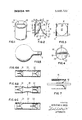
- FIG. 1 is a perspective view of apparatus in accordance with the present invention.
- FIG. 2 is a view similar to FIG. 1 cut away in section to see the insideof the assembly. I
- FIG. 3 is an elevational sectional view of the structure shown in FIG. 2 taken along line 33 in the direction of the arrows.
- FIG. 4 is an end view of the structure shown in FIG. 1 taken along line 44 in the direction of the arrows.
- FIG. 5 illustrates the present invention operating in one of its many uses.
- FIGS. 6A, B anc C are schematic side elevational sec- DESCRIPTION OF THE PREFERRED EMBODIMENT
- the assembly is of one piece formed such as by injection molding and of a plastic material such as polyvinyl chloride that is at least partially flexible.
- the valve includes a hollow cylindrical main body 12 providing a passage 13 between a first open end 14 and second open end 15.
- a pair of lip members 16 and 16 is provided within the main body 12 and normally permits only one way flow of fluid or gas through passage 13 from the first end 14 to the second end 15.
- the valve can be manipulated as described below to permit flow in the opposite direction.
- the lip members 16 and 16' include peripheral portions 21 and 21', respectively, joined to the inner surface of the main body member, each around substantially 180 of that inner surface, and at diametrically opposed points on the inner surface of the main body member 12 these peripheral portions 21 and 21' are joined together thereby forming a complete seal around the inside surface of the main body.
- a central body portion 22 and 22 for the respective lip members extends from the peripheral portion inwardly and longitudinally of the main body to the terminal end 23 of the lip members, and this central body portion curves inwardly toward axis of the main body between the peripheral portion and the terminal end 23.
- the terminal end 23 is spaced longitudinally within the main body a distance beyond the point where the peripheral portions 21 and 21 of the lip members meet, and the lip members are free from attachment to the main body over this distance so that the lip members l6 and 16 include generally flat end portions 25 and 25 adjacent the terminal end 23. Additionally the width of the lip members of these flat end portions 25 and 25 is reduced so that the terminal end is free from contact with the main body.
- the lip members are sealed together along their outside edge over the flat end portions 25 and 25 but are not sealed at the terminal end so that a slit like, normally closed opening 26 is provided at the terminal end 23 with this opening positioned on a line intersecting the axis of the main body in a plane normal to the axis.
- the central body portions 22 and 22' of the lip members 16 and 16 are thicker than the flat end portions 25 and 25' to aid in producing the desired sea] at the terminal end 23.
- the main body 12 is provided with enlarged rims 27 and 27' at the first and second ends 14 and to aid in attachment to other members.
- the assembly can be utilized as a two way valve such as for closing a toy balloon as illustrated in FIG. 5.
- air or fluid directed from the first end 14 into the main body 12 forces the flat end portions 25 and 25 adjacent the terminal end 23 of the lips apart to widen opening 26 for passage of the air or fluid through passage 13.
- the pressure on the large area central body portions of the lip members causes the central body portions to converge toward one another forcing the flat end portions 25 and 25 to-- gether thereby closing and sealing the slit opening 26. This seal is maintained until the pressure at the first end 14 is increased or until the main body is deformed so as to open the slit opening 26.
- valves of PVC No. 40 and PVC No. 60 have been constructed in accordance with this invention and successfully operated.
- the particular valves include main body thicknesses of 0.06 inch with the central body portion of the lip members 0.08 inch thick formed on a 0.687 inch radius and with the flat end portions 0.02 inch thick.
- valve construction can be made simply and efficiently and sold at a very low price so as to be used as a throw away valve for a toy balloon.
- valve can be used to seal specified fluids or gases in the balloon-like structure such as are collected by highway patrolmen giving drunk driver tests.
- the material and thicknesses of the structure can be selected so that the device serves as a pressure release valve for a prescribed pressure or as a one way check valve.
- One such check valve made of PVC No. 60 has been tested for 18 hours on a water hose holding psi without leaking a single drop.
- the combination can act as a noise maker in which case it is desired to have the lip members project from the second end of the main body.
- a pump can be provided when two flow control assemblies 31 and 32 are similarly oriented and sealed at their periphery within a common elongated passage 33.
- the left hand valve opens and the right hand valve remains sealed closed due to the movement of the lip members.
- the left hand assembly returns to its normal sealed condition and the right hand member which was acting as a check valve opens to admit air for the next pumping stroke.
- the structure not only serves as a control for fluid passing therethrough but as a gripping member 41 for articles such as a fibrous member 42 porous to fluid inserted through the opening as shown in FIG. 7.
- a flow control assembly comprising:
- each lip member having a peripheral portion connected to the inner surface of said main body member around substantially of the inner surface of said main body and joined to the other lip member forming a complete seal around said main body and a central body portion extending from said peripheral portion longitudinally of said main body to the lip member terminal end and defining a slit opening there with the other lip member,
- each lip member curved inwardly toward the axis of said main body between said peripheral portion and said slit opening with the curve of greater radius than the radius of the main body
- said lip members joined together except for a slit like, normally closed opening on a line intersecting the axis of said main body in a plane normal to said axis,
- said lip member central portion having a thickness 5 greater than the thickness of the adjacent peripheral and terminal end portions
- An integral one piece flow control assembly of plastic at least partially flexible comprising:
- a hollow cylindrical main body defining a flow passage therewithin and a pair of lip members extending inwardly and longitudinally of said main body to a terminal end for controlling flow through such passage
- each lip member having a peripheral portion connected to the inner suface of said main body member around substantially of the inner surface of said main body and joined to the other lip member forming a complete seal around said main body,
- the central body portion curved inwardly toward the axis of said main body, and having a radius greater than the radius of said main body
- each lip central body portion having a thickness greater than the thickness of the adjacent peripheral end flat end portions.
Abstract
An integral one piece flow control assembly is described having a hollow cylindrical main body defining a passage therethrough and a pair of lip members extending inwardly and longitudinally of said main body to a terminal end for controlling the flow through the passage. The lip members have a peripheral portion connected to the inner surface of the body and a central body portion extending from the peripheral portion to a terminal end portion defining a normally closed slit opening. Each lip member is curved inwardly toward the axis of the main body. Pressure in one direction presses the slit closed, and pressure in the opposite direction opens the slit. A pair of such flow control assemblies oriented in the same direction within a passage provide an inexpensive pump.
Description
United States Patent [191 Souza July 9, 1974 [54] FLOW CONTROL ASSEMBLY 66,612 4/1948 Denmark 417/478 [75] Inventor: Augustine A. Souza, San Jose, Calif. P I E C J H rzmary xammer usar [73] Assignee. Robert N. Noyce, Los Altos, Calif. Assistant Examiner Leonard Smith [22] Filed: Mar. 4, 1971 Attorney, Agent, or FirmLimbach, Limbach &
Appl. No.: 120,963
[52] US. Cl 137/525.1, 417/478, 417/566,
417/567. [51] Int. Cl. Fl6k 15/16 [58] Field of Search 417/568, 566, 567, 478, 417/479, 480; 137/5251 [56] References Cited UNITED STATES PATENTS 723,042 3/1903 Schwerin 417/454 X 2,219,604 10/1940 Trotter 417/478 X 2,662,724 12/1953 Kravagna 137/5251 2,954,738 10/1960 Di Vette 137/525.l X 2,986,098 5/1961 Trout et a1 417/566 2,989,052 6/1961 Broman 137/5251 X 3,148,624 9/1964 Baldwin 417/478 X 3,148,696 9/1964 Hoke 137/5251 X 4/1942 Germany l37/525.l
Sutton [57] ABSTRACT An integral one piece flow control assembly is described having a hollow cylindrical main body defining a passage therethrough and a pair of lip members extending inwardly and longitudinally of said main body to a terminal end for controlling the flow through the passage. The lip members have a peripheral portion connected to 'the inner surface of the body and a central body portion extending from the peripheral portion to a terminal end portion defining a normally closed slit opening. Each lip member is curved inwardly toward the axis of the main body. Pressure in one direction presses the slit closed, and pressure in the opposite. direction opens the slit. A pair of such flow control assemblies oriented in the same direction within a passage provide an inexpensive pump.
2 Claims, 9 Drawing Figures w mmm 91m 3.822.720 I 7r Ir III FIG. 7
' INVENTOR. AUCUSTINE A.SOUZA ,-ATTORNEY S 1 FLOW CONTROL ASSEMBLY The present invention is directed to a flow control assembly and more particularly to an inexpensive valve.
BACKGROUND prevented their widespread use. The construction of certain other valve assemblies has been sufficiently complicated so that the valve could not be manufactured cheaply enough for use as an inexpensive throw away valve.
THE PRESENT INVENTION The objective of the present invention is to provide a simple, one piece flow control assembly which can be simply and inexpensively manufactured.
In accordance with the present invention a valve or flow control assembly is provided having a hollow cylindrical main body defining a flow passage therethrough and a pair of lip members extending inwardly and longitudinally of the main body from a peripheral portion connected to the inner surface of the body around substantially 180 to a terminal end portion defining a slit opening between lip members. Each lip member is curved inwardly toward the axis of the main body between the peripheral portion and the slit opening whereby pressure against the concave side of the lip members presses these lip members together sealing the slit closed and pressure on the opposite side opens the slit.
A valve structure in accordance with this invention can provide a good way check valve, a pressure release valve, or a pressure reducing valve. In accordance with another aspect of the present invention the main body and lip members are integrally formed together of a plastic material at least partially flexible such as a polyvinyl chloride. With this construction a two way valve can be provided. With fluid pressure applied against the concave side of the lip members thereby closing and sealing the slit opening, the cylindrical main body can be squeezed along a line parallel to the length of the slit opening for effectively deforming the lip members and opening the slit. This provides a valve assembly that will automatically close inresponse to fluid pressure directed therethrough in only one direction but which can also be opened under the application of such pressure.
Other features of the present invention insure a good sea] at the slit. In accordance with one aspect of the present invention the lip members are provided with generally flat portions which are adjacent their terminal ends and which are free fromdirect connection to the main body so that the lips are free to flex in response to fluid pressure either to open or close the slit. Additionally minor deformation of the cylindrical main body or failure of the main body to return to its precise original shape after deformation will not prevent achieving the desired seal at the lips. However, gross deformation of the main body will transmit the deformation through the lips to open the slit as desired.
In accordance with another aspect of the present invention the thickness of the lip members is greater in the central portion thereof than in the flat portion adjacent the terminal ends, again assuring that the terminal ends of the lips are sufficiently more flexible than the remainder of the body to provide the good seal desired.
In accordance with still another aspect of the present invention a pair of valve structures constructed in accordance with the present invention can be oriented in the same direction within a fluid passage to serve as a pump when the passage is deformed successively to open and close the valves.
These and other features and advantages will become more apparent upon a perusal of the followingspecification taken in conjunction with the accompanying drawings wherein similar characters of reference refer to similar structures in each of the several views.
DESCRIPTION OF THE DRAWINGS FIG. 1 is a perspective view of apparatus in accordance with the present invention.
FIG. 2 is a view similar to FIG. 1 cut away in section to see the insideof the assembly. I
FIG. 3 is an elevational sectional view of the structure shown in FIG. 2 taken along line 33 in the direction of the arrows.
FIG. 4 is an end view of the structure shown in FIG. 1 taken along line 44 in the direction of the arrows.
FIG. 5 illustrates the present invention operating in one of its many uses.
FIGS. 6A, B anc C are schematic side elevational sec- DESCRIPTION OF THE PREFERRED EMBODIMENT Referring now to FIGS. 1-4 a two way valve 11 constructed in accordance with thepresent invention is illustrated. The assembly is of one piece formed such as by injection molding and of a plastic material such as polyvinyl chloride that is at least partially flexible. The valve includes a hollow cylindrical main body 12 providing a passage 13 between a first open end 14 and second open end 15.
A pair of lip members 16 and 16 is provided within the main body 12 and normally permits only one way flow of fluid or gas through passage 13 from the first end 14 to the second end 15. The valve can be manipulated as described below to permit flow in the opposite direction.
The lip members 16 and 16' include peripheral portions 21 and 21', respectively, joined to the inner surface of the main body member, each around substantially 180 of that inner surface, and at diametrically opposed points on the inner surface of the main body member 12 these peripheral portions 21 and 21' are joined together thereby forming a complete seal around the inside surface of the main body. A central body portion 22 and 22 for the respective lip members extends from the peripheral portion inwardly and longitudinally of the main body to the terminal end 23 of the lip members, and this central body portion curves inwardly toward axis of the main body between the peripheral portion and the terminal end 23.
The terminal end 23 is spaced longitudinally within the main body a distance beyond the point where the peripheral portions 21 and 21 of the lip members meet, and the lip members are free from attachment to the main body over this distance so that the lip members l6 and 16 include generally flat end portions 25 and 25 adjacent the terminal end 23. Additionally the width of the lip members of these flat end portions 25 and 25 is reduced so that the terminal end is free from contact with the main body.
The lip members are sealed together along their outside edge over the flat end portions 25 and 25 but are not sealed at the terminal end so that a slit like, normally closed opening 26 is provided at the terminal end 23 with this opening positioned on a line intersecting the axis of the main body in a plane normal to the axis. As best shown in FIG. 2 the central body portions 22 and 22' of the lip members 16 and 16 are thicker than the flat end portions 25 and 25' to aid in producing the desired sea] at the terminal end 23.
In the embodiment illustrated the main body 12 is provided with enlarged rims 27 and 27' at the first and second ends 14 and to aid in attachment to other members. In the embodiment illustrated it is preferred to have the terminal end 23 of the lip members within the main body, but as will be pointed out below, there are certain embodiments of the present invention where it is desirable to have the terminal end 23 project beyond the end of the main body.
The assembly can be utilized as a two way valve such as for closing a toy balloon as illustrated in FIG. 5. For operation of the device it will be appreciated that air or fluid directed from the first end 14 into the main body 12 forces the flat end portions 25 and 25 adjacent the terminal end 23 of the lips apart to widen opening 26 for passage of the air or fluid through passage 13. However, once the pressure at the first end 14 is reduced below that at the second end 15, the pressure on the large area central body portions of the lip members causes the central body portions to converge toward one another forcing the flat end portions 25 and 25 to-- gether thereby closing and sealing the slit opening 26. This seal is maintained until the pressure at the first end 14 is increased or until the main body is deformed so as to open the slit opening 26.
When a force is applied to the main body in a line parallel to the slit opening 26 and in the region of the central body portions 22 and 22' preferably in an axial plane containing the line of slit opening 26, the central body portions 22 and 22' of the main body are deformed outwardly thereby reducing the length of the slit opening 26 and opening the slit for passage of air or fluid. Upon release of this pressure the lip members will return to their previous position and seal the opening 26.
One inch valves of PVC No. 40 and PVC No. 60 have been constructed in accordance with this invention and successfully operated. The particular valves include main body thicknesses of 0.06 inch with the central body portion of the lip members 0.08 inch thick formed on a 0.687 inch radius and with the flat end portions 0.02 inch thick.
It will be appreciated that this valve construction can be made simply and efficiently and sold at a very low price so as to be used as a throw away valve for a toy balloon. Alternatively the valve can be used to seal specified fluids or gases in the balloon-like structure such as are collected by highway patrolmen giving drunk driver tests.
As pointed out above the material and thicknesses of the structure can be selected so that the device serves as a pressure release valve for a prescribed pressure or as a one way check valve. One such check valve made of PVC No. 60 has been tested for 18 hours on a water hose holding psi without leaking a single drop.
If a balloon is attached to the first end 14 of the de vice, the combination can act as a noise maker in which case it is desired to have the lip members project from the second end of the main body.
As shown in FIGS. 6A-C a pump can be provided when two flow control assemblies 31 and 32 are similarly oriented and sealed at their periphery within a common elongated passage 33. When the wall of the passage between the two is squeezed (as shown in FIG. 6B) the left hand valve opens and the right hand valve remains sealed closed due to the movement of the lip members. Then, as shown in FIG. 6C, when the pressure is removed, the left hand assembly returns to its normal sealed condition and the right hand member which was acting as a check valve opens to admit air for the next pumping stroke.
It will also be appreciated that the structure not only serves as a control for fluid passing therethrough but as a gripping member 41 for articles such as a fibrous member 42 porous to fluid inserted through the opening as shown in FIG. 7.
What is claimed is:
l. A flow control assembly comprising:
a hollow cylindrical main body defining a flow passage therewithin and a pair of lip members extending inwardly and longitudinally of said main body to a terminal end for controlling flow through such passage, each lip member having a peripheral portion connected to the inner surface of said main body member around substantially of the inner surface of said main body and joined to the other lip member forming a complete seal around said main body and a central body portion extending from said peripheral portion longitudinally of said main body to the lip member terminal end and defining a slit opening there with the other lip member,
each lip member curved inwardly toward the axis of said main body between said peripheral portion and said slit opening with the curve of greater radius than the radius of the main body,
at least part of the lip member central body portions projecting longitudinally within said main body to said terminal end free from said main body member,
said lip members joined together except for a slit like, normally closed opening on a line intersecting the axis of said main body in a plane normal to said axis,
said lip member central portion having a thickness 5 greater than the thickness of the adjacent peripheral and terminal end portions,
whereby fluid pressure against the concave side of said lip members presses said lip members sealing said slit closed and pressure in the opposite direction opens said slit.
2. An integral one piece flow control assembly of plastic at least partially flexible comprising:
a hollow cylindrical main body defining a flow passage therewithin and a pair of lip members extending inwardly and longitudinally of said main body to a terminal end for controlling flow through such passage,
each lip member having a peripheral portion connected to the inner suface of said main body member around substantially of the inner surface of said main body and joined to the other lip member forming a complete seal around said main body,
a central body portion extending from said peripheral portion longitudinally of said main body and,
a flat end portion extending to the lip member terminal end from said central body portion where said peripheral portions join,
the central body portion curved inwardly toward the axis of said main body, and having a radius greater than the radius of said main body,
said flat end portions of lesser width than the diameter of said main body and joined to one another along their sides except for a slit like, normally closed opening at the terminal end,
each lip central body portion having a thickness greater than the thickness of the adjacent peripheral end flat end portions.
Claims (2)
1. A flow control assembly comprising: a hollow cylindrical main body defining a flow passage therewithin and a pair of lip members extending inwardly and longitudinally of said main body to a terminal end for controlling flow through such passage, each lip member having a peripheral portion connected to the inner surface of said main body member around substantially 180* of the inner surface of said main body and joined to the other lip member forming a complete seal around said main body and a central body portion extending from said peripheral portion longitudinally of said main body to the lip member terminal end and defining a slit opening there with the other lip member, each lip member curved inwardly toward the axis of said main body between said peripheral portion and said slit opening with the curve of greater radius than the radius of the main body, at least part of the lip member central body portions projecting longitudinally within said main body to said terminal end free from said main body member, said lip members joined together except for a slit like, normally closed opening on a line intersecting the axis of said main body in a plane normal to said axis, said lip member central portion having a thickness greater than the thickness of the adjacent peripheral and terminal end portions, whereby fluid pressure against the concave side of said lip members presses said lip members sealing said slit closed and pressure in the opposite direction opens said slit.
2. An integral one piece flow control assembly of plastic at least partially flexible comprising: a hollow cylindrical main body defining a flow passage therewithin and a pair of lip members extending inwardly and longitudinally of said main body to a terminal end for controlling flow through such passage, each lip member having a peripheral portion connected to the inner suface of said main body member around substantially 180* of the inner surface of said main body and joined to the other lip member forming a complete seal around said main body, a central body portion extending from said peripheral portion longitudinally of said main body and, a flat end portion extending to the lip member terminal end from said central body portion where said peripheral portions join, the central body portion curved inwardly toward the axis of said main body, and having a radius Greater than the radius of said main body, said flat end portions of lesser width than the diameter of said main body and joined to one another along their sides except for a slit like, normally closed opening at the terminal end, each lip central body portion having a thickness greater than the thickness of the adjacent peripheral end flat end portions.
Priority Applications (1)
| Application Number | Priority Date | Filing Date | Title |
|---|---|---|---|
| US00120963A US3822720A (en) | 1971-03-04 | 1971-03-04 | Flow control assembly |
Applications Claiming Priority (1)
| Application Number | Priority Date | Filing Date | Title |
|---|---|---|---|
| US00120963A US3822720A (en) | 1971-03-04 | 1971-03-04 | Flow control assembly |
Publications (1)
| Publication Number | Publication Date |
|---|---|
| US3822720A true US3822720A (en) | 1974-07-09 |
Family
ID=22393566
Family Applications (1)
| Application Number | Title | Priority Date | Filing Date |
|---|---|---|---|
| US00120963A Expired - Lifetime US3822720A (en) | 1971-03-04 | 1971-03-04 | Flow control assembly |
Country Status (1)
| Country | Link |
|---|---|
| US (1) | US3822720A (en) |
Cited By (100)
| Publication number | Priority date | Publication date | Assignee | Title |
|---|---|---|---|---|
| US3901272A (en) * | 1974-01-04 | 1975-08-26 | Ford Motor Co | Unidirectional flow control valve |
| US3931831A (en) * | 1974-05-02 | 1976-01-13 | French George F | Elastic check valve and method of construction |
| US4039639A (en) * | 1975-04-10 | 1977-08-02 | Richard L. Kankel | Liquid entraining system of the humidifier and nebulizer type |
| US4240630A (en) * | 1978-04-10 | 1980-12-23 | Hoffman Allan C | Game ball check valve |
| US4411844A (en) * | 1982-02-11 | 1983-10-25 | Outboard Marine Corporation | Priming system for a vented bowl carburetor |
| US4416308A (en) * | 1979-11-30 | 1983-11-22 | Bower James F | Flexible one-way valve and method of producing |
| EP0139347A1 (en) * | 1983-09-26 | 1985-05-02 | Vernay Laboratories,Inc. | Valve assembly |
| US4535819A (en) * | 1984-06-04 | 1985-08-20 | Vernay Laboratories, Inc. | Valve assembly |
| US4604095A (en) * | 1983-01-04 | 1986-08-05 | Coloplast A/S | Return valve for a bag for collecting liquid excretions from the human body |
| US4662544A (en) * | 1985-07-11 | 1987-05-05 | Eagle Manufacturing Company | Apparatus for dispensing fluid |
| US4708167A (en) * | 1985-12-04 | 1987-11-24 | Toshimichi Koyanagi | Check valve |
| US4758198A (en) * | 1986-09-18 | 1988-07-19 | Ringstone Co., Ltd. | Gas-inflatable toy with plural bladders and valve means |
| US4810123A (en) * | 1987-05-13 | 1989-03-07 | Power Flo Products Corp. | Fountain applicator handle with specific check valve |
| US4911314A (en) * | 1986-01-20 | 1990-03-27 | Schneider Bernardus J J A | Stopper for a container such as a bottle, and a pump connectable thereto for extraction of gaseous medium from or pumping in thereof into the container |
| US4995864A (en) * | 1989-08-15 | 1991-02-26 | Imed Corporation | Dual chamber pumping apparatus |
| US5010925A (en) * | 1990-04-09 | 1991-04-30 | Vernay Laboratories, Inc. | Normally closed duckbill valve assembly |
| US5031785A (en) * | 1990-02-14 | 1991-07-16 | Epicurean International Corp. | Combination vacuum/pressure pump and valve stopper for food or drink containers |
| US5073168A (en) * | 1988-10-05 | 1991-12-17 | Danforth John W | Y-adaptor and percutaneous sheath for intravascular catheters |
| US5085349A (en) * | 1990-02-08 | 1992-02-04 | Fawcett Roger R | Resilient valve and dispensing system for bicyclists |
| US5098385A (en) * | 1990-04-26 | 1992-03-24 | Baxter International Inc. | Two-way valve for infusion devices |
| US5263203A (en) * | 1991-10-07 | 1993-11-23 | Riddell, Inc. | Integrated pump mechanism and inflatable liner for protective |
| US5295892A (en) * | 1992-11-04 | 1994-03-22 | Show-Me Balloons | Balloon having a self sealing valve and method of making same |
| US5301707A (en) * | 1993-04-12 | 1994-04-12 | Vernay Laboratories, Inc. | Anti-whistling duckbill valve |
| FR2703403A1 (en) * | 1993-03-29 | 1994-10-07 | Meillor Sa | Priming bulb especially for a fuel circuit for a diesel engine |
| US5381563A (en) * | 1992-12-24 | 1995-01-17 | Roger Carrier | Check valve, and hydromassaging apparatus comprising at least one of such a check valve |
| US5601207A (en) * | 1996-03-13 | 1997-02-11 | Paczonay; Joseph R. | Bite valve having a plurality of slits |
| US5645404A (en) * | 1994-12-29 | 1997-07-08 | Z Industry, Inc. | Personal fluid dispensing device |
| US5791510A (en) * | 1996-03-13 | 1998-08-11 | Paczonay; Joseph R. | Self sealing bite valve |
| WO1999004187A1 (en) * | 1997-07-15 | 1999-01-28 | Unilever Plc | Duckbill valve |
| US5911406A (en) * | 1995-09-15 | 1999-06-15 | Winefordner; Carl | Liquid dispensing and item storage system with orally activated valve |
| US5971357A (en) * | 1997-11-14 | 1999-10-26 | Wolfe Tory Medical, Inc. | Fluid delivery valve |
| US6032831A (en) * | 1998-07-17 | 2000-03-07 | Came1Bak Products, Inc. | Personal hydration system with an improved mouthpiece |
| US6062436A (en) * | 1998-04-02 | 2000-05-16 | Owens-Illinois Closure Inc. | Flexible vented self-sealing dispensing valve |
| US6092551A (en) * | 1998-05-19 | 2000-07-25 | Chesebrough-Pond's Usa Co., Division Of Conopco, Inc. | Duckbill valve |
| WO2000066447A1 (en) * | 1999-05-04 | 2000-11-09 | Georg Menshen Gmbh & Co. Kg | Slotted closing valve for openings of containers |
| WO2000077429A1 (en) * | 1999-06-15 | 2000-12-21 | Ip.One Pty. Ltd. | A non-return valve |
| US6189736B1 (en) | 1997-01-17 | 2001-02-20 | Niagara Pump Corporation | Condiment dispensing apparatus |
| US6273128B1 (en) | 1999-08-11 | 2001-08-14 | Joseph R. Paczonay | Apparatus for controlling the flow of fluid |
| US6283137B1 (en) | 1999-03-01 | 2001-09-04 | Steven Joseph Malecki | Siphon assembly with one way priming valve |
| US6402190B1 (en) * | 1999-06-30 | 2002-06-11 | Takata (Europe) Vehicle Safety Technology Gmbh | Non return valve for an airbag |
| US6497348B2 (en) | 2000-07-10 | 2002-12-24 | Camelbak Products, Inc. | Hydration system with improved fluid delivery system |
| US6568557B2 (en) | 2000-03-16 | 2003-05-27 | Cosco Management, Inc. | Spill proof training cup |
| US6708950B2 (en) | 2002-03-15 | 2004-03-23 | Wolfe Tory Medical | Bite valve |
| US6764064B2 (en) | 2002-02-12 | 2004-07-20 | Hydrapak | Fluid dispensing and storage system with a drink valve |
| AU775326B2 (en) * | 1999-06-15 | 2004-07-29 | Global Valve Technology Pty Limited | A non-return valve |
| WO2004083697A1 (en) * | 2003-03-17 | 2004-09-30 | Global Valve Technology Pty Ltd | A sports ball valve |
| USD499793S1 (en) | 2003-03-17 | 2004-12-14 | Baxter International Inc. | Valve |
| US20050167391A1 (en) * | 2003-03-03 | 2005-08-04 | Aqua Pyrenees S.A. | Stopper device for containers, such as cylinders, equipped with a neck of the water fountain type |
| US20050167631A1 (en) * | 2002-01-30 | 2005-08-04 | Horton David R. | Valve |
| US20060071432A1 (en) * | 2004-09-29 | 2006-04-06 | Staudner Rupert A | Seal for trocar |
| US7037303B2 (en) | 2001-07-06 | 2006-05-02 | Opticon Medical, Inc. | Urinary flow control valve |
| US20060174870A1 (en) * | 2000-03-04 | 2006-08-10 | Deem Mark E | Methods and devices for use in performing pulmonary procedures |
| EP1715228A1 (en) * | 2005-04-20 | 2006-10-25 | ROEDIGER VAKUUM- und HAUSTECHNIK GmbH | Vacuum sewage system |
| DE102005022777A1 (en) * | 2005-05-12 | 2006-11-16 | Behr Gmbh & Co. Kg | Differential pressure valve |
| US20070048069A1 (en) * | 2003-03-07 | 2007-03-01 | Moss Alan B S | Toilet cleaning apparatus |
| US20070138121A1 (en) * | 2005-11-16 | 2007-06-21 | The Last Straw, Llc | Drinking devices for children with integrated valve |
| US20070187891A1 (en) * | 2006-02-16 | 2007-08-16 | Designomite, Llc | Game piece |
| US20070262164A1 (en) * | 2006-05-01 | 2007-11-15 | Daniel Gelfand | Drinking Straw |
| US7347136B2 (en) | 2005-12-08 | 2008-03-25 | Diversified Dynamics Corporation | Airless sprayer with hardened cylinder |
| US20080216224A1 (en) * | 2007-03-06 | 2008-09-11 | Good Mark D | Flush toilet with flexible waste arm |
| US20090071982A1 (en) * | 2007-09-13 | 2009-03-19 | L'oreal | Dispensing pump for product storage and dispensing container and container provided with such a pump |
| US20090137972A1 (en) * | 2006-07-14 | 2009-05-28 | Ryu Katayama | Container with Liquid Squeeze Nozzle |
| US7540380B2 (en) | 2005-07-25 | 2009-06-02 | Diversified Dynamics Corporation | Roller rest enclosure |
| US7556447B2 (en) | 2005-07-25 | 2009-07-07 | Diversified Dynamics Corporation | Metered twist paint stick |
| US20090294715A1 (en) * | 2006-08-24 | 2009-12-03 | Global Valve Technology Limited | Centreline flow valve |
| US20110106024A1 (en) * | 2008-07-14 | 2011-05-05 | Ryu Katayama | Container with a squeezed nozzle and lever |
| US20110163134A1 (en) * | 2010-01-06 | 2011-07-07 | Bloom Kenneth S | Dispensing valve |
| US20110168802A1 (en) * | 2010-01-12 | 2011-07-14 | S.C. Johnson & Son, Inc. | Spill/Leak Resistant Seal for a Wicking Device |
| US20120052165A1 (en) * | 2010-08-25 | 2012-03-01 | Cryovac, Inc. | Package With On-Demand Product Elevation |
| US8220156B2 (en) | 2010-10-28 | 2012-07-17 | The Gillette Company | Liquid dispensing hair removal kit |
| US8510957B2 (en) | 2010-10-28 | 2013-08-20 | The Gillette Company | Applicator with a baffle for a hair removal device |
| US8608034B2 (en) | 2011-02-18 | 2013-12-17 | Berry Plastics Corporation | Dispensing valve |
| JP2014046946A (en) * | 2012-08-31 | 2014-03-17 | Nippon Kimu Kk | Backflow prevention member |
| US20140110029A1 (en) * | 2012-10-24 | 2014-04-24 | Robert Leon Benedict | Vein pump assembly for air maintenance tire |
| US20140158129A1 (en) * | 2010-09-22 | 2014-06-12 | Clovershield, Inc. | Transversely-activated valve for a therapeutic vaporizer bag attachment system |
| US8782904B2 (en) | 2010-10-28 | 2014-07-22 | The Gillette Company | Applicator for liquid dispensing hair removal device |
| US8793879B2 (en) | 2010-10-28 | 2014-08-05 | The Gillette Company | Cartridge biasing applicator for a hair removal device |
| US8832942B2 (en) | 2010-10-28 | 2014-09-16 | The Gillette Company | Hair removal device with cartridge retention cover |
| US8931177B2 (en) | 2010-10-28 | 2015-01-13 | The Gillette Company | Handle for a liquid dispensing hair removal device |
| US9010363B2 (en) | 2013-06-24 | 2015-04-21 | The Rectorseal Corporation | Drain valve |
| US9044541B2 (en) | 2005-12-02 | 2015-06-02 | C. R. Bard, Inc. | Pressure activated proximal valves |
| CN104675681A (en) * | 2014-12-20 | 2015-06-03 | 华南理工大学 | Miniature air-liquid pump |
| US9139991B2 (en) | 2011-01-31 | 2015-09-22 | The Rectorseal Corporation | Floor drain valve with resiliently mounted rigid flappers |
| US9156175B2 (en) | 2011-12-09 | 2015-10-13 | The Gillette Company | Fluid applicator for a personal-care appliance |
| CN105480522A (en) * | 2015-11-26 | 2016-04-13 | 成都九十度工业产品设计有限公司 | Bacteriostatic milk storage tank |
| US9321425B2 (en) * | 2011-12-24 | 2016-04-26 | Autoliv Development Ab | Airbag comprising two chambers and a gas flow channel connecting the two chambers with a valve being located in the gas flow channel |
| US9416986B2 (en) | 2013-06-24 | 2016-08-16 | The Rectorseal Corporation | Valve for roof vent |
| US20160264272A1 (en) * | 2015-03-09 | 2016-09-15 | Gary Dean Growden | Method of reusing modified atmospheric packaging |
| US9669671B2 (en) | 2012-10-24 | 2017-06-06 | The Goodyear Tire & Rubber Company | Vein pump assembly for air maintenance tire |
| US20170156525A1 (en) * | 2014-06-23 | 2017-06-08 | Pernod Ricard Sa | Duckbill Valve Arrangement For A Beverage Dispensing Container |
| USD796903S1 (en) | 2016-06-03 | 2017-09-12 | Shock Doctor, Inc. | Hydration bladder |
| US9789620B2 (en) | 2010-10-28 | 2017-10-17 | The Gillette Company | Pump for a liquid dispensing hair removal device |
| USD806476S1 (en) | 2016-06-03 | 2018-01-02 | Shock Doctor, Inc. | Hydration bladder |
| WO2018006949A1 (en) * | 2016-07-05 | 2018-01-11 | Wapro Ab | A check valve and a method for controlling a flow of fluid by fluid pressure |
| US20190001081A1 (en) * | 2015-12-21 | 2019-01-03 | 3M Innovative Properties Company | Flow governors for use in medicinal inhalers |
| DE102017217634A1 (en) * | 2017-10-04 | 2019-04-04 | B. Braun Melsungen Ag | Valve device for a medical fluid line system |
| US20200263796A1 (en) * | 2019-02-18 | 2020-08-20 | The Boeing Company | Valves having flexible membranes |
| US11077278B2 (en) | 2010-09-22 | 2021-08-03 | Robert Irving Pratt, JR. | Therapeutic vaporizer |
| US11109580B1 (en) * | 2010-06-03 | 2021-09-07 | Field System Research, Llc | Fishing line accessory systems, methods, and apparatuses |
| US11577035B2 (en) | 2010-09-22 | 2023-02-14 | Robert Irving Pratt, JR. | Therapeutic vaporizer |
Citations (10)
| Publication number | Priority date | Publication date | Assignee | Title |
|---|---|---|---|---|
| US723042A (en) * | 1901-03-19 | 1903-03-17 | Hardman Rubber Company | Valve for syringes, atomizers, &c. |
| US2219604A (en) * | 1939-11-20 | 1940-10-29 | George C Trotter | Dispensing device |
| DE719253C (en) * | 1939-06-25 | 1942-04-02 | Messerschmitt Boelkow Blohm | Spring valve for fuel injection pumps of internal combustion engines |
| DK66612C (en) * | 1944-06-09 | 1948-04-12 | Erik Trudsoe | Diaphragm pump. |
| US2662724A (en) * | 1948-12-27 | 1953-12-15 | Kravagna Cut | Check valve |
| US2954738A (en) * | 1957-11-08 | 1960-10-04 | Honeywell Regulator Co | Diaphragm pump |
| US2986098A (en) * | 1959-10-23 | 1961-05-30 | Cardiovascular Res Foundation | Expansible chamber liquid pump |
| US2989052A (en) * | 1957-09-12 | 1961-06-20 | Baxter Laboratories Inc | Parenteral fluid equipment |
| US3148624A (en) * | 1961-06-21 | 1964-09-15 | Alan W Baldwin | Hydraulic pump |
| US3148696A (en) * | 1961-06-08 | 1964-09-15 | Dresser Ind | Acorn valve for punching t |
-
1971
- 1971-03-04 US US00120963A patent/US3822720A/en not_active Expired - Lifetime
Patent Citations (10)
| Publication number | Priority date | Publication date | Assignee | Title |
|---|---|---|---|---|
| US723042A (en) * | 1901-03-19 | 1903-03-17 | Hardman Rubber Company | Valve for syringes, atomizers, &c. |
| DE719253C (en) * | 1939-06-25 | 1942-04-02 | Messerschmitt Boelkow Blohm | Spring valve for fuel injection pumps of internal combustion engines |
| US2219604A (en) * | 1939-11-20 | 1940-10-29 | George C Trotter | Dispensing device |
| DK66612C (en) * | 1944-06-09 | 1948-04-12 | Erik Trudsoe | Diaphragm pump. |
| US2662724A (en) * | 1948-12-27 | 1953-12-15 | Kravagna Cut | Check valve |
| US2989052A (en) * | 1957-09-12 | 1961-06-20 | Baxter Laboratories Inc | Parenteral fluid equipment |
| US2954738A (en) * | 1957-11-08 | 1960-10-04 | Honeywell Regulator Co | Diaphragm pump |
| US2986098A (en) * | 1959-10-23 | 1961-05-30 | Cardiovascular Res Foundation | Expansible chamber liquid pump |
| US3148696A (en) * | 1961-06-08 | 1964-09-15 | Dresser Ind | Acorn valve for punching t |
| US3148624A (en) * | 1961-06-21 | 1964-09-15 | Alan W Baldwin | Hydraulic pump |
Cited By (144)
| Publication number | Priority date | Publication date | Assignee | Title |
|---|---|---|---|---|
| US3901272A (en) * | 1974-01-04 | 1975-08-26 | Ford Motor Co | Unidirectional flow control valve |
| US3931831A (en) * | 1974-05-02 | 1976-01-13 | French George F | Elastic check valve and method of construction |
| US4039639A (en) * | 1975-04-10 | 1977-08-02 | Richard L. Kankel | Liquid entraining system of the humidifier and nebulizer type |
| US4240630A (en) * | 1978-04-10 | 1980-12-23 | Hoffman Allan C | Game ball check valve |
| US4416308A (en) * | 1979-11-30 | 1983-11-22 | Bower James F | Flexible one-way valve and method of producing |
| US4411844A (en) * | 1982-02-11 | 1983-10-25 | Outboard Marine Corporation | Priming system for a vented bowl carburetor |
| US4604095A (en) * | 1983-01-04 | 1986-08-05 | Coloplast A/S | Return valve for a bag for collecting liquid excretions from the human body |
| EP0139347A1 (en) * | 1983-09-26 | 1985-05-02 | Vernay Laboratories,Inc. | Valve assembly |
| US4535818A (en) * | 1983-09-26 | 1985-08-20 | Vernay Laboratories, Inc. | Valve assembly |
| US4535819A (en) * | 1984-06-04 | 1985-08-20 | Vernay Laboratories, Inc. | Valve assembly |
| US4662544A (en) * | 1985-07-11 | 1987-05-05 | Eagle Manufacturing Company | Apparatus for dispensing fluid |
| US4708167A (en) * | 1985-12-04 | 1987-11-24 | Toshimichi Koyanagi | Check valve |
| US4911314A (en) * | 1986-01-20 | 1990-03-27 | Schneider Bernardus J J A | Stopper for a container such as a bottle, and a pump connectable thereto for extraction of gaseous medium from or pumping in thereof into the container |
| US4998633A (en) * | 1986-01-20 | 1991-03-12 | Schneider Bernardus J J A | Stopper for a container such as a bottle and including slit valve structure, for use with a pump for altering and thereafter maintaining altered pressure in the container |
| US4758198A (en) * | 1986-09-18 | 1988-07-19 | Ringstone Co., Ltd. | Gas-inflatable toy with plural bladders and valve means |
| US4810123A (en) * | 1987-05-13 | 1989-03-07 | Power Flo Products Corp. | Fountain applicator handle with specific check valve |
| US5073168A (en) * | 1988-10-05 | 1991-12-17 | Danforth John W | Y-adaptor and percutaneous sheath for intravascular catheters |
| US4995864A (en) * | 1989-08-15 | 1991-02-26 | Imed Corporation | Dual chamber pumping apparatus |
| US5085349A (en) * | 1990-02-08 | 1992-02-04 | Fawcett Roger R | Resilient valve and dispensing system for bicyclists |
| US5031785A (en) * | 1990-02-14 | 1991-07-16 | Epicurean International Corp. | Combination vacuum/pressure pump and valve stopper for food or drink containers |
| US5010925A (en) * | 1990-04-09 | 1991-04-30 | Vernay Laboratories, Inc. | Normally closed duckbill valve assembly |
| US5098385A (en) * | 1990-04-26 | 1992-03-24 | Baxter International Inc. | Two-way valve for infusion devices |
| US5263203A (en) * | 1991-10-07 | 1993-11-23 | Riddell, Inc. | Integrated pump mechanism and inflatable liner for protective |
| US5295892A (en) * | 1992-11-04 | 1994-03-22 | Show-Me Balloons | Balloon having a self sealing valve and method of making same |
| US5381563A (en) * | 1992-12-24 | 1995-01-17 | Roger Carrier | Check valve, and hydromassaging apparatus comprising at least one of such a check valve |
| FR2703403A1 (en) * | 1993-03-29 | 1994-10-07 | Meillor Sa | Priming bulb especially for a fuel circuit for a diesel engine |
| US5301707A (en) * | 1993-04-12 | 1994-04-12 | Vernay Laboratories, Inc. | Anti-whistling duckbill valve |
| US5645404A (en) * | 1994-12-29 | 1997-07-08 | Z Industry, Inc. | Personal fluid dispensing device |
| US5911406A (en) * | 1995-09-15 | 1999-06-15 | Winefordner; Carl | Liquid dispensing and item storage system with orally activated valve |
| US5791510A (en) * | 1996-03-13 | 1998-08-11 | Paczonay; Joseph R. | Self sealing bite valve |
| US5601207A (en) * | 1996-03-13 | 1997-02-11 | Paczonay; Joseph R. | Bite valve having a plurality of slits |
| US6213739B1 (en) | 1997-01-17 | 2001-04-10 | Niagara Pump Corporation | Linear peristaltic pump |
| US6189736B1 (en) | 1997-01-17 | 2001-02-20 | Niagara Pump Corporation | Condiment dispensing apparatus |
| AU728691B2 (en) * | 1997-07-15 | 2001-01-18 | Unilever Plc | Duckbill valve |
| WO1999004187A1 (en) * | 1997-07-15 | 1999-01-28 | Unilever Plc | Duckbill valve |
| US6136253A (en) * | 1997-07-15 | 2000-10-24 | Chesebrough-Pond's Usa, Division Of Conopco, Inc. | Method for molding duckbill valve |
| US5971357A (en) * | 1997-11-14 | 1999-10-26 | Wolfe Tory Medical, Inc. | Fluid delivery valve |
| US6062436A (en) * | 1998-04-02 | 2000-05-16 | Owens-Illinois Closure Inc. | Flexible vented self-sealing dispensing valve |
| US6298554B1 (en) | 1998-04-02 | 2001-10-09 | Owens-Illinois Closure Inc. | Flexible vented self-sealing dispensing valve |
| US6092551A (en) * | 1998-05-19 | 2000-07-25 | Chesebrough-Pond's Usa Co., Division Of Conopco, Inc. | Duckbill valve |
| US6364168B1 (en) | 1998-07-17 | 2002-04-02 | Camelbak Products, Inc. | Personal hydration system with an improved mouthpiece |
| US6032831A (en) * | 1998-07-17 | 2000-03-07 | Came1Bak Products, Inc. | Personal hydration system with an improved mouthpiece |
| US6070767A (en) * | 1998-07-17 | 2000-06-06 | Camelbak Products, Inc. | Personal hydration system with an improved mouthpiece |
| US6283137B1 (en) | 1999-03-01 | 2001-09-04 | Steven Joseph Malecki | Siphon assembly with one way priming valve |
| WO2000066447A1 (en) * | 1999-05-04 | 2000-11-09 | Georg Menshen Gmbh & Co. Kg | Slotted closing valve for openings of containers |
| US6450375B1 (en) | 1999-05-04 | 2002-09-17 | Georg Menshen Gmbh & Co. Kg | Slotted closing valve for openings of containers |
| US7028981B2 (en) | 1999-06-15 | 2006-04-18 | Ip.One Pty Ltd | Non-return valve |
| EP1210536A1 (en) * | 1999-06-15 | 2002-06-05 | IP. ONE PTY. Ltd | A non-return valve |
| WO2000077429A1 (en) * | 1999-06-15 | 2000-12-21 | Ip.One Pty. Ltd. | A non-return valve |
| EP1210536A4 (en) * | 1999-06-15 | 2002-08-28 | Ip One Pty Ltd | A non-return valve |
| AU775326B2 (en) * | 1999-06-15 | 2004-07-29 | Global Valve Technology Pty Limited | A non-return valve |
| US20060065316A1 (en) * | 1999-06-15 | 2006-03-30 | Horton David R | Non-return valve |
| US6824117B2 (en) | 1999-06-15 | 2004-11-30 | Ip. One Pty Ltd. | Non-return valve |
| US20040211468A1 (en) * | 1999-06-15 | 2004-10-28 | Horton David R | Non-return valve |
| US6402190B1 (en) * | 1999-06-30 | 2002-06-11 | Takata (Europe) Vehicle Safety Technology Gmbh | Non return valve for an airbag |
| US6273128B1 (en) | 1999-08-11 | 2001-08-14 | Joseph R. Paczonay | Apparatus for controlling the flow of fluid |
| US7662181B2 (en) * | 2000-03-04 | 2010-02-16 | Pulmonx Corporation | Methods and devices for use in performing pulmonary procedures |
| US20060174870A1 (en) * | 2000-03-04 | 2006-08-10 | Deem Mark E | Methods and devices for use in performing pulmonary procedures |
| US6568557B2 (en) | 2000-03-16 | 2003-05-27 | Cosco Management, Inc. | Spill proof training cup |
| US6497348B2 (en) | 2000-07-10 | 2002-12-24 | Camelbak Products, Inc. | Hydration system with improved fluid delivery system |
| US7037303B2 (en) | 2001-07-06 | 2006-05-02 | Opticon Medical, Inc. | Urinary flow control valve |
| US7201363B2 (en) | 2002-01-30 | 2007-04-10 | Global Valve Technology Pty Ltd. | Valve |
| US20050167631A1 (en) * | 2002-01-30 | 2005-08-04 | Horton David R. | Valve |
| US6764064B2 (en) | 2002-02-12 | 2004-07-20 | Hydrapak | Fluid dispensing and storage system with a drink valve |
| US6708950B2 (en) | 2002-03-15 | 2004-03-23 | Wolfe Tory Medical | Bite valve |
| US20050167391A1 (en) * | 2003-03-03 | 2005-08-04 | Aqua Pyrenees S.A. | Stopper device for containers, such as cylinders, equipped with a neck of the water fountain type |
| US20070048069A1 (en) * | 2003-03-07 | 2007-03-01 | Moss Alan B S | Toilet cleaning apparatus |
| US20060264278A1 (en) * | 2003-03-17 | 2006-11-23 | David Horton | Sports ball valve |
| USD499793S1 (en) | 2003-03-17 | 2004-12-14 | Baxter International Inc. | Valve |
| WO2004083697A1 (en) * | 2003-03-17 | 2004-09-30 | Global Valve Technology Pty Ltd | A sports ball valve |
| US20060071432A1 (en) * | 2004-09-29 | 2006-04-06 | Staudner Rupert A | Seal for trocar |
| EP1715228A1 (en) * | 2005-04-20 | 2006-10-25 | ROEDIGER VAKUUM- und HAUSTECHNIK GmbH | Vacuum sewage system |
| DE102005022777A1 (en) * | 2005-05-12 | 2006-11-16 | Behr Gmbh & Co. Kg | Differential pressure valve |
| US7540380B2 (en) | 2005-07-25 | 2009-06-02 | Diversified Dynamics Corporation | Roller rest enclosure |
| US7556447B2 (en) | 2005-07-25 | 2009-07-07 | Diversified Dynamics Corporation | Metered twist paint stick |
| US20070138121A1 (en) * | 2005-11-16 | 2007-06-21 | The Last Straw, Llc | Drinking devices for children with integrated valve |
| US9044541B2 (en) | 2005-12-02 | 2015-06-02 | C. R. Bard, Inc. | Pressure activated proximal valves |
| US9943678B2 (en) | 2005-12-02 | 2018-04-17 | C. R. Bard, Inc. | Pressure activated proximal valves |
| US11305102B2 (en) | 2005-12-02 | 2022-04-19 | C. R. Bard, Inc. | Pressure activated proximal valves |
| US7347136B2 (en) | 2005-12-08 | 2008-03-25 | Diversified Dynamics Corporation | Airless sprayer with hardened cylinder |
| US7441779B2 (en) * | 2006-02-16 | 2008-10-28 | Designomite, L.L.C. | Game piece |
| US20090014957A1 (en) * | 2006-02-16 | 2009-01-15 | Designomite, L.L.C. | Game piece |
| US20070187891A1 (en) * | 2006-02-16 | 2007-08-16 | Designomite, Llc | Game piece |
| US20070262164A1 (en) * | 2006-05-01 | 2007-11-15 | Daniel Gelfand | Drinking Straw |
| US9452869B2 (en) * | 2006-07-14 | 2016-09-27 | Ryu Katayama | Container with liquid squeeze nozzle |
| US20090137972A1 (en) * | 2006-07-14 | 2009-05-28 | Ryu Katayama | Container with Liquid Squeeze Nozzle |
| US8567435B2 (en) | 2006-08-24 | 2013-10-29 | Global Valve Technology Limited | Centreline flow valve |
| US20090294715A1 (en) * | 2006-08-24 | 2009-12-03 | Global Valve Technology Limited | Centreline flow valve |
| US8167587B2 (en) | 2007-03-06 | 2012-05-01 | Thetford Corporation | Pump assembly with reversible one-way valves |
| US7996929B2 (en) | 2007-03-06 | 2011-08-16 | Thetford Corporation | Flush toilet |
| US20080216905A1 (en) * | 2007-03-06 | 2008-09-11 | Dorsey Noah | Pump assembly with reversible one-way valves |
| US20080216225A1 (en) * | 2007-03-06 | 2008-09-11 | Juska Michael | Pump assembly for a flush toilet with mode selector |
| US20080216224A1 (en) * | 2007-03-06 | 2008-09-11 | Good Mark D | Flush toilet with flexible waste arm |
| US20090071982A1 (en) * | 2007-09-13 | 2009-03-19 | L'oreal | Dispensing pump for product storage and dispensing container and container provided with such a pump |
| US8496635B2 (en) * | 2008-07-14 | 2013-07-30 | Ryu Katayama | Container with a squeezed nozzle and lever |
| US20110106024A1 (en) * | 2008-07-14 | 2011-05-05 | Ryu Katayama | Container with a squeezed nozzle and lever |
| US20110163134A1 (en) * | 2010-01-06 | 2011-07-07 | Bloom Kenneth S | Dispensing valve |
| US8397957B2 (en) | 2010-01-06 | 2013-03-19 | Berry Plastics Corporation | Dispensing valve |
| US8794489B2 (en) | 2010-01-06 | 2014-08-05 | Berry Plastics Corporation | Dispensing valve |
| US20110168802A1 (en) * | 2010-01-12 | 2011-07-14 | S.C. Johnson & Son, Inc. | Spill/Leak Resistant Seal for a Wicking Device |
| US9919071B2 (en) * | 2010-01-12 | 2018-03-20 | S. C. Johnson & Son, Inc. | Spill/leak resistant seal for a wicking device |
| US11109580B1 (en) * | 2010-06-03 | 2021-09-07 | Field System Research, Llc | Fishing line accessory systems, methods, and apparatuses |
| US8357414B2 (en) * | 2010-08-25 | 2013-01-22 | Cryovac, Inc. | Package with on-demand product elevation |
| US20120052165A1 (en) * | 2010-08-25 | 2012-03-01 | Cryovac, Inc. | Package With On-Demand Product Elevation |
| US11577035B2 (en) | 2010-09-22 | 2023-02-14 | Robert Irving Pratt, JR. | Therapeutic vaporizer |
| US20140158129A1 (en) * | 2010-09-22 | 2014-06-12 | Clovershield, Inc. | Transversely-activated valve for a therapeutic vaporizer bag attachment system |
| US10926047B2 (en) | 2010-09-22 | 2021-02-23 | Robert Irving Pratt, JR. | Transversely-activated valve for a therapeutic vaporizer bag attachment system |
| US11077278B2 (en) | 2010-09-22 | 2021-08-03 | Robert Irving Pratt, JR. | Therapeutic vaporizer |
| US9061430B2 (en) | 2010-10-28 | 2015-06-23 | The Gillette Company | Applicator with a baffle for a hair removal device |
| US8510957B2 (en) | 2010-10-28 | 2013-08-20 | The Gillette Company | Applicator with a baffle for a hair removal device |
| US8782904B2 (en) | 2010-10-28 | 2014-07-22 | The Gillette Company | Applicator for liquid dispensing hair removal device |
| US8931177B2 (en) | 2010-10-28 | 2015-01-13 | The Gillette Company | Handle for a liquid dispensing hair removal device |
| US10232521B2 (en) | 2010-10-28 | 2019-03-19 | The Gillette Company Llc | Pump for a liquid dispensing hair removal device |
| US8220156B2 (en) | 2010-10-28 | 2012-07-17 | The Gillette Company | Liquid dispensing hair removal kit |
| US8793879B2 (en) | 2010-10-28 | 2014-08-05 | The Gillette Company | Cartridge biasing applicator for a hair removal device |
| US9789620B2 (en) | 2010-10-28 | 2017-10-17 | The Gillette Company | Pump for a liquid dispensing hair removal device |
| US8832942B2 (en) | 2010-10-28 | 2014-09-16 | The Gillette Company | Hair removal device with cartridge retention cover |
| US9139991B2 (en) | 2011-01-31 | 2015-09-22 | The Rectorseal Corporation | Floor drain valve with resiliently mounted rigid flappers |
| US8608034B2 (en) | 2011-02-18 | 2013-12-17 | Berry Plastics Corporation | Dispensing valve |
| US9156175B2 (en) | 2011-12-09 | 2015-10-13 | The Gillette Company | Fluid applicator for a personal-care appliance |
| US9321425B2 (en) * | 2011-12-24 | 2016-04-26 | Autoliv Development Ab | Airbag comprising two chambers and a gas flow channel connecting the two chambers with a valve being located in the gas flow channel |
| JP2014046946A (en) * | 2012-08-31 | 2014-03-17 | Nippon Kimu Kk | Backflow prevention member |
| US9669671B2 (en) | 2012-10-24 | 2017-06-06 | The Goodyear Tire & Rubber Company | Vein pump assembly for air maintenance tire |
| US20140110029A1 (en) * | 2012-10-24 | 2014-04-24 | Robert Leon Benedict | Vein pump assembly for air maintenance tire |
| US9010363B2 (en) | 2013-06-24 | 2015-04-21 | The Rectorseal Corporation | Drain valve |
| US9416986B2 (en) | 2013-06-24 | 2016-08-16 | The Rectorseal Corporation | Valve for roof vent |
| US20170156525A1 (en) * | 2014-06-23 | 2017-06-08 | Pernod Ricard Sa | Duckbill Valve Arrangement For A Beverage Dispensing Container |
| CN104675681A (en) * | 2014-12-20 | 2015-06-03 | 华南理工大学 | Miniature air-liquid pump |
| US20160264272A1 (en) * | 2015-03-09 | 2016-09-15 | Gary Dean Growden | Method of reusing modified atmospheric packaging |
| CN105480522A (en) * | 2015-11-26 | 2016-04-13 | 成都九十度工业产品设计有限公司 | Bacteriostatic milk storage tank |
| US20190001081A1 (en) * | 2015-12-21 | 2019-01-03 | 3M Innovative Properties Company | Flow governors for use in medicinal inhalers |
| US11376378B2 (en) * | 2015-12-21 | 2022-07-05 | Kindeva Drug Delivery, L.P. | Flow governors for use in medicinal inhalers |
| USD806476S1 (en) | 2016-06-03 | 2018-01-02 | Shock Doctor, Inc. | Hydration bladder |
| USD892554S1 (en) | 2016-06-03 | 2020-08-11 | Shock Doctor, Inc. | Hydration bladder |
| USD841399S1 (en) | 2016-06-03 | 2019-02-26 | Shock Doctor, Inc. | Hydration bladder |
| USD796903S1 (en) | 2016-06-03 | 2017-09-12 | Shock Doctor, Inc. | Hydration bladder |
| WO2018006949A1 (en) * | 2016-07-05 | 2018-01-11 | Wapro Ab | A check valve and a method for controlling a flow of fluid by fluid pressure |
| CN109603000A (en) * | 2017-10-04 | 2019-04-12 | B.布劳恩梅尔松根股份公司 | Valve gear for medical fluid pipe-line system |
| US11241567B2 (en) | 2017-10-04 | 2022-02-08 | B. Braun Melsungen Ag | Valve device for a medical fluid line system |
| EP3466482A1 (en) * | 2017-10-04 | 2019-04-10 | B. Braun Melsungen AG | Valve device for a medical fluid guidance system |
| DE102017217634A1 (en) * | 2017-10-04 | 2019-04-04 | B. Braun Melsungen Ag | Valve device for a medical fluid line system |
| CN109603000B (en) * | 2017-10-04 | 2023-05-23 | B.布劳恩梅尔松根股份公司 | Valve device for medical fluid line system |
| US20200263796A1 (en) * | 2019-02-18 | 2020-08-20 | The Boeing Company | Valves having flexible membranes |
| US11015727B2 (en) * | 2019-02-18 | 2021-05-25 | The Boeing Company | Valves having flexible membranes |
Similar Documents
| Publication | Publication Date | Title |
|---|---|---|
| US3822720A (en) | Flow control assembly | |
| US4913401A (en) | Valve apparatus | |
| US3525357A (en) | Pump valve apparatus | |
| US5800339A (en) | Urinary control valve | |
| US5730336A (en) | Dispensing valve for a flexible liquid container | |
| US3116747A (en) | Unitary rupturable check valve | |
| US4222407A (en) | One-way flex valve | |
| US5010925A (en) | Normally closed duckbill valve assembly | |
| US2859932A (en) | Valve | |
| US4008984A (en) | Pump apparatus | |
| US4064882A (en) | Tracheostomy tube with pressure relief valve | |
| US7028981B2 (en) | Non-return valve | |
| US6554589B2 (en) | Flexible tube pinch mechanism | |
| US4850393A (en) | All-plastic check valve | |
| US3342208A (en) | Resilient material valve | |
| CA2452309A1 (en) | Pressure actuated flow control valve | |
| KR920700712A (en) | Chemical continuous fluid injector with balun | |
| US4744391A (en) | Flow control valve | |
| DK0937926T3 (en) | Negative Pressure valve | |
| US2898078A (en) | Valve structure | |
| US3779236A (en) | Pressure relief valve for a sphygmomanometer | |
| US3949780A (en) | Two piece check valve | |
| US3158165A (en) | Valve assembly and method of making it | |
| US5823754A (en) | Manual pump | |
| US2692751A (en) | Valve for rubber tubes, syringes, and the like |