EP1013970B1 - Dispositif pour la transmission de couple d'un moteur à combustion interne, à un compresseur - Google Patents
Dispositif pour la transmission de couple d'un moteur à combustion interne, à un compresseur Download PDFInfo
- Publication number
- EP1013970B1 EP1013970B1 EP99123389A EP99123389A EP1013970B1 EP 1013970 B1 EP1013970 B1 EP 1013970B1 EP 99123389 A EP99123389 A EP 99123389A EP 99123389 A EP99123389 A EP 99123389A EP 1013970 B1 EP1013970 B1 EP 1013970B1
- Authority
- EP
- European Patent Office
- Prior art keywords
- hub
- entrainment
- belt pulley
- compressor
- overload protection
- Prior art date
- Legal status (The legal status is an assumption and is not a legal conclusion. Google has not performed a legal analysis and makes no representation as to the accuracy of the status listed.)
- Expired - Lifetime
Links
- 238000002485 combustion reaction Methods 0.000 title claims description 7
- 230000005540 biological transmission Effects 0.000 title claims description 5
- 238000013016 damping Methods 0.000 claims description 19
- 229920001971 elastomer Polymers 0.000 claims description 14
- 239000000806 elastomer Substances 0.000 claims description 8
- 239000004033 plastic Substances 0.000 claims description 4
- 238000004378 air conditioning Methods 0.000 claims description 3
- 239000000463 material Substances 0.000 claims description 2
- 238000009434 installation Methods 0.000 claims 1
- 239000002184 metal Substances 0.000 description 2
- 230000000903 blocking effect Effects 0.000 description 1
- 239000000969 carrier Substances 0.000 description 1
- 230000007812 deficiency Effects 0.000 description 1
- 238000007373 indentation Methods 0.000 description 1
- 230000002427 irreversible effect Effects 0.000 description 1
- 238000000926 separation method Methods 0.000 description 1
Images


Classifications
-
- F—MECHANICAL ENGINEERING; LIGHTING; HEATING; WEAPONS; BLASTING
- F02—COMBUSTION ENGINES; HOT-GAS OR COMBUSTION-PRODUCT ENGINE PLANTS
- F02B—INTERNAL-COMBUSTION PISTON ENGINES; COMBUSTION ENGINES IN GENERAL
- F02B63/00—Adaptations of engines for driving pumps, hand-held tools or electric generators; Portable combinations of engines with engine-driven devices
- F02B63/06—Adaptations of engines for driving pumps, hand-held tools or electric generators; Portable combinations of engines with engine-driven devices for pumps
-
- F—MECHANICAL ENGINEERING; LIGHTING; HEATING; WEAPONS; BLASTING
- F02—COMBUSTION ENGINES; HOT-GAS OR COMBUSTION-PRODUCT ENGINE PLANTS
- F02B—INTERNAL-COMBUSTION PISTON ENGINES; COMBUSTION ENGINES IN GENERAL
- F02B67/00—Engines characterised by the arrangement of auxiliary apparatus not being otherwise provided for, e.g. the apparatus having different functions; Driving auxiliary apparatus from engines, not otherwise provided for
- F02B67/04—Engines characterised by the arrangement of auxiliary apparatus not being otherwise provided for, e.g. the apparatus having different functions; Driving auxiliary apparatus from engines, not otherwise provided for of mechanically-driven auxiliary apparatus
- F02B67/06—Engines characterised by the arrangement of auxiliary apparatus not being otherwise provided for, e.g. the apparatus having different functions; Driving auxiliary apparatus from engines, not otherwise provided for of mechanically-driven auxiliary apparatus driven by means of chains, belts, or like endless members
-
- F—MECHANICAL ENGINEERING; LIGHTING; HEATING; WEAPONS; BLASTING
- F16—ENGINEERING ELEMENTS AND UNITS; GENERAL MEASURES FOR PRODUCING AND MAINTAINING EFFECTIVE FUNCTIONING OF MACHINES OR INSTALLATIONS; THERMAL INSULATION IN GENERAL
- F16H—GEARING
- F16H55/00—Elements with teeth or friction surfaces for conveying motion; Worms, pulleys or sheaves for gearing mechanisms
- F16H55/32—Friction members
- F16H55/36—Pulleys
- F16H2055/366—Pulleys with means providing resilience or vibration damping
Definitions
- the invention relates to a device for transmitting a Torque from an internal combustion engine to an accessory, especially the compressor of an air conditioner Motor vehicle, with a hub for connection to the accessory shaft and one rotatable on the accessory housing arranged pulley, wherein the pulley and the Hub via a vibration damping component and another Component for overload protection are connected to each other, wherein the overload protection is designed such that the Connection between pulley and hub when exceeding a predetermined torque immediately and permanently interrupted becomes.
- EP 0 793 031 A1 discloses a Device has become known in the between the over a Belt drive connected to the crankshaft pulley of the Compressor and the hub of the compressor shaft a device arranged for vibration damping and overload protection is that is to ensure that when a predetermined Torque, namely by the stoppage of Compressor occurring torque, the compressor shaft of the pulley is uncoupled, leaving the pulley can rotate freely and the function of the rest of the drive train in case of failure of the compressor is not affected.
- This overload protection is the device of this known Device also at the same time for vibration damping, um harmful vibrations from the crankshaft via the belt drive be transferred to the pulley, from the compressor or the compressor shaft away.
- this driver element both for vibration damping than also serves to overload protection, it has in practice proved very difficult, this driver element be designed exactly so that it has both the vibration damping function perfectly fulfilled as well as exactly at the appearance of the predetermined torque ensures the overload protection.
- Another device is known from DE 198 21 990 A1, at which separates the pulley and hub via two separate ones Components are connected together, namely a component for Vibration damping, which is formed by a rubber ring, and a component for overload protection, that of a tortuous Spring is formed, which is mounted on the drive shaft and arranged and configured so that they occur when the load is deformed. If the overload occurs, then the torque transmission from the drive shaft to the pulley reversibly interrupted as long as the overload occurs. However, it is difficult to do such a spring exactly the same way be interpreted that they occur when the specified torque safely ensures the overload function. Also difficult is the design of the rubber ring for vibration damping, especially the available space for this Rubber ring is limited. A similar device is EP 0 867 631 A1.
- a generic device with the features of the preamble of claim 1 is known from JP 10252857 A.
- the pulley inside with a substantially over the entire width of the pulley extending rubber ring connected as a damper the radially inner side of a Torque transmission element is arranged, the axially outside the pulley provided with axially extended teeth is, referring to a ring-like projection of the element are located.
- a hub area is provided, the has a radial extent. On the outer circumference of this radial extent teeth are provided in the axial direction, which engage in the teeth of the torque transmitting element.
- the object of the invention is a generic device to improve, while maintaining an exactly responsive Overload protection improves the vibration damping becomes.
- This object is in a device of the initially designated Kind erfingdungsconce solved by the pulley is connected to a drive plate, which outside edge with circumferentially spaced drivers is provided, each driver in each case in each case limited by radial ribs driving space of the pulley engages, and wherein the component for vibration damping from between the edges of the respective driver and the associated ribs of the pulley Elastomer elements is formed.
- the device thus also has a decoupling of both functions, i. It is a component for vibration damping and another component separate therefrom Overload protection provided so that both components separated can be interpreted from each other.
- the component for vibration damping is formed by individual elastomeric elements, which can be specifically designed so that the desired Vibration damping is feasible. These elastomeric elements are space-saving within a limited by radial ribs Mit technicallyraumes the pulley arranged in the Engage driver of a drive plate, which on the other hand over the component for overload protection with the compressor shaft communicates.
- the elastomeric elements can be formed in different ways be. So they can be advantageous as a common ring part be formed, which particularly simplifies the assembly. Alternatively, you can also attach to the respective ribs of the pulley or vulcanized to the respective driver be.
- the center hole then deforms elliptical and The evasive rubber may be in the radial Impressions buckle and thereby no friction on the pulley Experienced.
- the component for overload protection formed by the drive plate is that on the hub positively and / or non-positively in such a way is held against rotation that the connection at a certain predetermined torque is canceled.
- the form and / or Frictional connection can in different ways will be realized.
- the positive and / or non-positive connection between the drive plate and the hub of a splined profiling with zakkenförmigen Wedges is formed. It is then the positive and / or non-positive connection designed so that when exceeded a predetermined torque, which by the Standstill of the compressor shaft occurs, the wedge-like Profiling can slip freely, allowing the torque transmission between hub and drive plate is canceled.
- the drive plate made of plastic, while the hub e.g. consists of a sintered metal.
- the hub e.g. consists of a sintered metal.
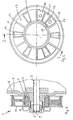
- FIG. 1 An inventive device for transmitting a torque from an internal combustion engine, not shown a compressor is generally designated 1 in FIG.
- This device 1 initially has a hub 2, which for rotatably connected to a compressor shaft 3 of a compressor Air conditioning or the like. Serves.
- the compressor housing 4 of this compressor is indicated in Figure 1 only.
- the pulley 6 is via a poly-V-belt, not shown preferably with the crankshaft of an internal combustion engine a motor vehicle and is thus of this driven.
- the pulley 6 serves to the compressor shaft 3 and thus to drive the compressor.
- a device for vibration damping and overload protection provided, formed by two separate components is.
- the component for overload protection is a drive plate 8 formed, the positive and / or non-positive the hub 2 is arranged.
- the positive and / or non-positive Connection between the drive plate 8 and the hub 2 is preferably by a wedge-like profile 9 formed with serrated wedges, as best seen in FIG. 6 evident.
- This figure can also be seen that the hub 2 preferably via a conventional spline 10 at the Compressor shaft 3 is arranged.
- the drive plate 8 made of plastic and the hub 3 preferably made of a suitable metal, so that through appropriate material selection and suitable geometric Design of the splined profiling 9 the overload protection can be designed specifically so that when the Compressor shaft is stopped by fault of the compressor and thus a corresponding torque occurs, the drive plate 8 free and irreversible on the hub 3 "slips", that is, when the overload occurs, the connection between the hub 3 and the drive plate 8 directly and permanently ended.
- the drive plate 8 is the outer edge side with circumferentially from each other provided spaced carriers 11, each Driver 11 each in a respective radial ribs 12th limited driving space 13 of the pulley 6 engages. to Vibration damping are between the edges of each Driver 11 and the associated ribs 12 of the pulley 6 elastomeric elements 14 are provided which the vibration damping guarantee.
- each elastomeric element 14 is preferably the respective Elastomer element 14 at the two radial ends semicircular vaulted, these vaults are designated 15.
- each elastomeric element 14 with a Middle hole 16 provided. This offers the advantage that in the Entrainment movement, the center hole 16 deformed elliptical and while the outer edges of the elastomeric element 14 in the semicircular indentations 15 can deform without Frictionally applied to the pulley 6.
- the elastomeric elements 14 may be a common ring element They can also on the ribs 12 of the pulley. 6 or vulcanized to the drivers 11, but they can also, as shown in Figure 2, designed as a single part be.
- the invention is not limited to the illustrated embodiment limited. Further embodiments are possible without leaving the basic idea.
- the positive and / or non-positive connection between the Hub 2 and the drive plate 8 realized in another way It is essential that a separation of the overload protection and the vibration damping by separate components is guaranteed.
Claims (8)
- Dispositif pour transmettre un couple de rotation depuis un moteur à combustion interne vers un ensemble accessoire, en particulier le compresseur d'une installation de climatisation d'un véhicule automobile, comprenant un moyeu destiné à être relié à l'arbre de l'ensemble accessoire et une poulie à gorge agencée en rotation sur le carter du groupe accessoire, la poulie à gorge et le moyeu étant reliés l'un à l'autre via un composant destiné à l'amortissement de vibrations et un autre composant destiné à la sécurité anti-surcharge, ledit composant anti-surcharge étant ainsi réalisé que la jonction entre la poulie à gorge et le moyeu est interrompue immédiatement et durablement lors du dépassement d'un couple de rotation prédéterminé,
caractérisé en ce que
la poulie à gorge (6) est reliée à un disque d'entraínement (8) qui est pourvu, du côté de sa bordure extérieure, de tocs d'entraínement (11) écartés les uns des autres en sens périphérique,
chaque toc d'entraínement (11) s'engage dans un logement d'entraínement respectif (13), délimité par des nervures radiales respectives (12), dans la poulie à gorge (6), et
le composant destiné à l'amortissement des vibrations est formé par des éléments élastomères (14) agencés entre les bordures du toc d'entraínement respectif (11) et les nervures associées (12) de la poulie à gorge (6). - Dispositif selon la revendication 1, caractérisé en ce que la totalité des éléments élastomères (14) sont réalisés sous forme de composant annulaire commun.
- Dispositif selon la revendication 1, caractérisé en ce que les éléments élastomères (14) sont fixés par vulcanisation sur les nervures respectives (12) de la poulie à gorge.
- Dispositif selon la revendication 1, caractérisé en ce que les éléments élastomères respectifs (14) sont fixés par vulcanisation sur le toc d'entraínement respectif (11).
- Dispositif selon la revendication 1 ou l'une des suivantes, caractérisé en ce que les éléments élastomères (14) sont réalisés sous forme concave aux deux extrémités radiales, et sont dotés d'un trou central (16) au milieu.
- Dispositif selon la revendication 1 ou l'une des suivantes, caractérisé en ce que le composant destiné à la sécurité anti-surcharge est réalisé par la poulie d'entraínement (8), laquelle est maintenue solidaire en rotation sur le moyeu (2), par coopération de formes et/ou de forces de telle façon que la liaison est annulée pour un couple de rotation prédéterminé donné.
- Dispositif selon la revendication 6, caractérisé en ce que la liaison par coopération de formes et/ou de forces entre le disque d'entraínement (8) et le moyeu (2) est formée par un profil (9) en forme d'ondulations en coin, avec des coins en forme de dents.
- Dispositif selon la revendication 1 ou l'une des suivantes, caractérisé en ce que le disque d'entraínement (8) est en matière synthétique.
Applications Claiming Priority (2)
| Application Number | Priority Date | Filing Date | Title |
|---|---|---|---|
| DE19860150 | 1998-12-24 | ||
| DE19860150A DE19860150B4 (de) | 1998-12-24 | 1998-12-24 | Vorrichtung zur Übertragung eines Drehmoments von einem Verbrennungsmotor zu einem Kompressor |
Publications (3)
| Publication Number | Publication Date |
|---|---|
| EP1013970A2 EP1013970A2 (fr) | 2000-06-28 |
| EP1013970A3 EP1013970A3 (fr) | 2003-01-02 |
| EP1013970B1 true EP1013970B1 (fr) | 2005-03-16 |
Family
ID=7892722
Family Applications (1)
| Application Number | Title | Priority Date | Filing Date |
|---|---|---|---|
| EP99123389A Expired - Lifetime EP1013970B1 (fr) | 1998-12-24 | 1999-11-24 | Dispositif pour la transmission de couple d'un moteur à combustion interne, à un compresseur |
Country Status (7)
| Country | Link |
|---|---|
| US (1) | US6336883B1 (fr) |
| EP (1) | EP1013970B1 (fr) |
| JP (1) | JP3578687B2 (fr) |
| BR (1) | BR9907431A (fr) |
| DE (2) | DE19860150B4 (fr) |
| ES (1) | ES2237018T3 (fr) |
| PT (1) | PT1013970E (fr) |
Families Citing this family (33)
| Publication number | Priority date | Publication date | Assignee | Title |
|---|---|---|---|---|
| US6575631B2 (en) | 1999-05-31 | 2003-06-10 | Nsk Ltd. | Rolling bearing and rolling bearing device |
| DE10149070B4 (de) * | 2000-10-05 | 2004-07-08 | Nsk Ltd. | Wälzlager und Wälzlagervorrichtung |
| JP4617584B2 (ja) * | 2001-03-15 | 2011-01-26 | 株式会社デンソー | 動力伝達装置 |
| JP2002349596A (ja) * | 2001-05-22 | 2002-12-04 | Denso Corp | トルク伝達装置 |
| CN1524168A (zh) * | 2001-07-06 | 2004-08-25 | �Ǵĺ�˾ | 风扇的张紧皮带轮 |
| BR0301654C5 (pt) * | 2003-04-10 | 2006-01-17 | Aurelio Mayorca | Sistema e equipamento dinâmico para refrigerar |
| JP3927959B2 (ja) * | 2003-09-26 | 2007-06-13 | バンドー化学株式会社 | 伝動ベルト用プーリ及びベルト伝動装置 |
| DE10354049A1 (de) * | 2003-11-19 | 2005-06-30 | Winkelmann Palsis Motortechnik Gmbh & Co.Kg | Vorrichtung zur Übertragung eines Drehmomentes von einem Verbrennungsmotor zu einem Nebenaggregat |
| DE102004002668A1 (de) | 2004-01-18 | 2005-09-22 | Bakelite Ag | Vorrichtung zur Übertragung eines Drehmomentes von einem Motor zu einem Kompressor |
| DE102004018390A1 (de) * | 2004-04-16 | 2005-12-22 | Ina-Schaeffler Kg | Vorrichtung für einen Verbrennungsmotor |
| DE102004031852A1 (de) | 2004-06-30 | 2006-01-19 | Robert Bosch Gmbh | Vorrichtung zur Übertragung eines Drehmoments sowie Verfahren zur Herstellung einer Vorrichtung zur Übertragung eines Drehmoments |
| DE102004035596A1 (de) * | 2004-07-22 | 2006-03-16 | Zexel Valeo Compressor Europe Gmbh | Vorrichtung zur Übertragung von Momenten, insbesondere für Verdichter von Kraftfahrzeug-Klimaanlagen |
| DE102004038420A1 (de) | 2004-07-30 | 2006-03-23 | Robert Bosch Gmbh | Vorrichtung zur Übertragung eines Drehmoments |
| DE102004038248B3 (de) * | 2004-08-05 | 2006-03-09 | Küster Automotive Control Systems GmbH | Elektromotorische Antriebseinheit für eine Feststellbremseinrichtung von Kraftfahrzeugen mit Rutschkupplung |
| DE102004056487B4 (de) * | 2004-11-23 | 2006-10-19 | Winkelmann Powertrain Components Gmbh & Co. Kg | Mitnehmerscheibe |
| US20070209899A1 (en) * | 2006-03-09 | 2007-09-13 | Keming Liu | Decoupling vibration isolator |
| BRPI0604660B1 (pt) * | 2006-10-11 | 2020-12-15 | Sabo Industria E Comercio De Autopeças S/A | Reparo para extremidades de eixo virabrequim |
| US20080135356A1 (en) * | 2006-12-06 | 2008-06-12 | Yungh-Siang Lin | Transmission motor structure |
| US8632431B2 (en) * | 2006-12-11 | 2014-01-21 | Schaeffler Technologies AG & Co. KG | Drive wheel of an auxiliary unit belt drive of an internal combustion engine |
| JP2008215564A (ja) * | 2007-03-07 | 2008-09-18 | Jtekt Corp | 樹脂巻き部品 |
| US8272982B2 (en) * | 2008-07-09 | 2012-09-25 | Ct Drives, Llc | Cam damped pulley for rotary devices |
| AT507825B1 (de) * | 2009-02-03 | 2011-02-15 | Ge Jenbacher Gmbh & Co Ohg | Stationäre brennkraftmaschine |
| DE102011111819B4 (de) | 2011-08-27 | 2015-03-05 | Winkelmann Powertrain Components Gmbh & Co. Kg | "Entkoppelte Riemenscheibe" |
| KR101824436B1 (ko) | 2011-11-28 | 2018-02-01 | 한온시스템 주식회사 | 압축기 |
| JP5701799B2 (ja) * | 2012-03-09 | 2015-04-15 | 株式会社日立製作所 | 非常ブレーキ装置、エレベータ装置及び綱車 |
| FR2991019B1 (fr) * | 2012-05-24 | 2015-07-24 | Skf Ab | Dispositif de poulie pour compresseur de climatisation |
| CN102767607B (zh) * | 2012-07-25 | 2015-05-06 | 武汉正通传动技术有限公司 | 一种带扭矩限制的同步带轮 |
| CN102767608B (zh) * | 2012-07-25 | 2014-07-30 | 武汉正通传动技术有限公司 | 带扭矩限制器的同步带轮 |
| WO2014157276A1 (fr) * | 2013-03-29 | 2014-10-02 | 小倉クラッチ株式会社 | Dispositif de transmission d'énergie motrice |
| FR3006711B1 (fr) * | 2013-06-07 | 2015-06-05 | Skf Ab | Systeme d'entrainement de pompe a eau et procede de montage |
| CN110657083A (zh) * | 2019-08-16 | 2020-01-07 | 泰州朗润电子科技有限公司 | 一种用于汽车空调变排量压缩机的驱动盘 |
| CN110657084A (zh) * | 2019-09-24 | 2020-01-07 | 泰州朗润电子科技有限公司 | 一种汽车变排量压缩机用驱动盘 |
| CN113457828B (zh) * | 2021-07-05 | 2022-09-30 | 利恩传动设备(常州)有限公司 | 一种用于破碎机的扭矩限制器 |
Family Cites Families (24)
| Publication number | Priority date | Publication date | Assignee | Title |
|---|---|---|---|---|
| US3372561A (en) * | 1965-03-03 | 1968-03-12 | Rotary Hoes Ltd | Means for limiting torque transmission |
| DE6910144U (de) * | 1969-03-13 | 1969-08-21 | Stromag Maschf | Elastische kupplung |
| US3932956A (en) * | 1975-01-08 | 1976-01-20 | Ideal Toy Corporation | Toy vehicle clutch |
| US4473363A (en) * | 1981-08-20 | 1984-09-25 | Mccutchan Jr Ben O | Composite plastic and metal pulley construction |
| FR2536225B1 (fr) * | 1982-11-16 | 1986-03-07 | Thomson Brandt | Dispositif de selection de stations pour un recepteur radiophonique |
| US4722722A (en) * | 1986-06-27 | 1988-02-02 | Jepmar Research | Rotatable drive member formed from injection molded plastics material with preform insert |
| JPH0639105Y2 (ja) * | 1986-07-23 | 1994-10-12 | サンデン株式会社 | プ−リ−直結型コンプレッサ− |
| US5377962A (en) * | 1992-08-08 | 1995-01-03 | Firma Carl Freudenberg | Rotational vibration damper |
| DE4300083A1 (de) * | 1993-01-06 | 1994-07-07 | Masch Und Werkzeugbau Gmbh | Überlastkupplung |
| DE4320938C2 (de) * | 1993-06-24 | 1995-05-24 | Freudenberg Carl Fa | Elastische Kupplung |
| US5426304A (en) * | 1994-01-13 | 1995-06-20 | Texas Instruments Incorporated | Infrared detector thermal isolation structure and method |
| JPH07259962A (ja) * | 1994-03-18 | 1995-10-13 | Toyoda Gosei Co Ltd | ダンパプーリおよびその製造方法 |
| JP2875754B2 (ja) * | 1994-04-15 | 1999-03-31 | 小倉クラッチ株式会社 | 電磁連結装置のアーマチュア組立体 |
| GB9420741D0 (en) * | 1994-10-14 | 1994-11-30 | Litens Automotive Inc | Crankshaft decoupler |
| DE4440885C2 (de) * | 1994-11-17 | 1997-08-21 | Freudenberg Carl Fa | Torsionsschwingungsdämpfer |
| FR2734034B1 (fr) * | 1995-05-12 | 1997-07-11 | Hutchinson | Dispositif de decouplage, notamment poulie decoupleuse, destine a un vehicule automobile |
| JP3671571B2 (ja) * | 1996-02-29 | 2005-07-13 | 株式会社デンソー | 動力伝達装置 |
| JPH10159866A (ja) * | 1996-11-22 | 1998-06-16 | Nok Corp | トルクリミッタ |
| JPH10267046A (ja) * | 1997-03-24 | 1998-10-06 | Toyota Autom Loom Works Ltd | 動力伝達機構 |
| ES2205483T3 (es) * | 1997-05-07 | 2004-05-01 | Litens Automotive Partnership | Sistema motriz de serpentin con desacoplador del alternador de rueda libre. |
| JP3939393B2 (ja) * | 1997-05-08 | 2007-07-04 | サンデン株式会社 | 動力伝達機構 |
| JPH10318280A (ja) * | 1997-05-16 | 1998-12-02 | Toyota Autom Loom Works Ltd | 動力伝達機構 |
| DE19749761C2 (de) * | 1997-11-11 | 2000-07-06 | Freudenberg Carl Fa | Entkoppelte Riemenscheibe |
| JP3421619B2 (ja) * | 1998-12-11 | 2003-06-30 | 小倉クラッチ株式会社 | 動力伝達装置 |
-
1998
- 1998-12-24 DE DE19860150A patent/DE19860150B4/de not_active Expired - Fee Related
-
1999
- 1999-11-24 EP EP99123389A patent/EP1013970B1/fr not_active Expired - Lifetime
- 1999-11-24 PT PT99123389T patent/PT1013970E/pt unknown
- 1999-11-24 ES ES99123389T patent/ES2237018T3/es not_active Expired - Lifetime
- 1999-11-24 DE DE59911761T patent/DE59911761C5/de not_active Expired - Fee Related
- 1999-12-20 US US09/467,451 patent/US6336883B1/en not_active Expired - Fee Related
- 1999-12-22 JP JP36480699A patent/JP3578687B2/ja not_active Expired - Fee Related
- 1999-12-23 BR BR9907431-1A patent/BR9907431A/pt active Search and Examination
Also Published As
| Publication number | Publication date |
|---|---|
| EP1013970A2 (fr) | 2000-06-28 |
| DE59911761D1 (de) | 2005-04-21 |
| BR9907431A (pt) | 2000-08-08 |
| EP1013970A3 (fr) | 2003-01-02 |
| PT1013970E (pt) | 2005-06-30 |
| US6336883B1 (en) | 2002-01-08 |
| DE19860150A1 (de) | 2000-07-13 |
| DE59911761C5 (de) | 2007-08-30 |
| JP3578687B2 (ja) | 2004-10-20 |
| ES2237018T3 (es) | 2005-07-16 |
| DE19860150B4 (de) | 2004-06-24 |
| JP2000227155A (ja) | 2000-08-15 |
Similar Documents
| Publication | Publication Date | Title |
|---|---|---|
| EP1013970B1 (fr) | Dispositif pour la transmission de couple d'un moteur à combustion interne, à un compresseur | |
| DE19729421B4 (de) | Schwungradanordnung | |
| DE3448587C2 (de) | Kupplungsscheibe mit Torsionsschwingungsdämpfer | |
| DE60200178T2 (de) | Riemenscheibeneinheit, insbesondere für eine Brennkraftmaschine | |
| EP1774196B1 (fr) | Dispositif de transmission d'un moment de rotation | |
| EP2097657B1 (fr) | Amortisseur des vibrations torsionnelles présentant un élément primaire multicomposant | |
| DE1680049C3 (de) | Kupplungsscheibe mit Schwingungs dämpfer | |
| EP1555449A1 (fr) | Dispositif de transmission de couple d'un moteur à un compresseur | |
| WO2012075984A1 (fr) | Amortisseur à poulie | |
| EP0502527A2 (fr) | Disque pour embrayage à friction de véhicule automobile | |
| DE4420251A1 (de) | Reibungskupplung | |
| WO2008113316A1 (fr) | Amortisseur de vibrations torsionnelles | |
| DE4140643C2 (de) | Kupplungsscheibe mit elastischer Zentrierung | |
| EP1801460B1 (fr) | Unité motrice ayant un composant moteur interne et un composant moteur externe | |
| DE10047242C1 (de) | Anlasserrad für ein Kraftfahrzeug oder dgl. | |
| DE19704451B4 (de) | Reibungsvorrichtung für Torsionsdämpfer | |
| DE112005000162B4 (de) | Reibungskupplung, insbesondere für ein Kraftfahrzeug, die differenzierte Reibungsmittel umfaßt | |
| DE10203006B4 (de) | Beschlag für einen Fahrzeugsitz | |
| DE112016000285T5 (de) | Drehmomentübertragungsvorrichtung mit elastischem Federstreifen ausgerüstet mit einem Zentrifugalmassen-Torsionsschwingungsdämpfer | |
| EP3234390B1 (fr) | Dispositif de transmission d'un couple d'un moteur à combustion interne vers un groupe auxiliaire | |
| DE102006057793A1 (de) | Triebrad eines Nebenaggregatezugs eines Verbrennungsmotors | |
| DE102017118321B4 (de) | Rolle mit Schutzvorrichtung | |
| DE10354049A1 (de) | Vorrichtung zur Übertragung eines Drehmomentes von einem Verbrennungsmotor zu einem Nebenaggregat | |
| DE102010005423B4 (de) | Riemenscheibenanordnung zum Anbringen an der Kurbelwelle | |
| DE10080940B3 (de) | Torsionsdämpfer für eine Kupplung und eine Reibscheibengruppe für diesen Torsionsdämpfer |
Legal Events
| Date | Code | Title | Description |
|---|---|---|---|
| PUAI | Public reference made under article 153(3) epc to a published international application that has entered the european phase |
Free format text: ORIGINAL CODE: 0009012 |
|
| AK | Designated contracting states |
Kind code of ref document: A2 Designated state(s): AT BE CH CY DE DK ES FI FR GB GR IE IT LI LU MC NL PT SE |
|
| AX | Request for extension of the european patent |
Free format text: AL;LT;LV;MK;RO;SI |
|
| PUAL | Search report despatched |
Free format text: ORIGINAL CODE: 0009013 |
|
| AK | Designated contracting states |
Kind code of ref document: A3 Designated state(s): AT BE CH CY DE DK ES FI FR GB GR IE IT LI LU MC NL PT SE |
|
| AX | Request for extension of the european patent |
Free format text: AL;LT;LV;MK;RO;SI |
|
| RIC1 | Information provided on ipc code assigned before grant |
Free format text: 7F 16H 55/36 A, 7B 60K 25/02 B, 7F 16D 9/06 B, 7F 16H 55:14 Z, 7F 16H 35:10 Z |
|
| 17P | Request for examination filed |
Effective date: 20030412 |
|
| AKX | Designation fees paid |
Designated state(s): DE ES FR GB IT PT |
|
| 17Q | First examination report despatched |
Effective date: 20040414 |
|
| RAP1 | Party data changed (applicant data changed or rights of an application transferred) |
Owner name: WINKELMANN PALSIS MOTORTECHNIK GMBH& CO.KG |
|
| GRAP | Despatch of communication of intention to grant a patent |
Free format text: ORIGINAL CODE: EPIDOSNIGR1 |
|
| GRAS | Grant fee paid |
Free format text: ORIGINAL CODE: EPIDOSNIGR3 |
|
| GRAA | (expected) grant |
Free format text: ORIGINAL CODE: 0009210 |
|
| AK | Designated contracting states |
Kind code of ref document: B1 Designated state(s): DE ES FR GB IT PT |
|
| REG | Reference to a national code |
Ref country code: GB Ref legal event code: FG4D Free format text: NOT ENGLISH |
|
| GBT | Gb: translation of ep patent filed (gb section 77(6)(a)/1977) |
Effective date: 20050316 |
|
| REG | Reference to a national code |
Ref country code: IE Ref legal event code: FG4D Free format text: GERMAN |
|
| REF | Corresponds to: |
Ref document number: 59911761 Country of ref document: DE Date of ref document: 20050421 Kind code of ref document: P |
|
| REG | Reference to a national code |
Ref country code: PT Ref legal event code: SC4A Free format text: AVAILABILITY OF NATIONAL TRANSLATION Effective date: 20050422 |
|
| REG | Reference to a national code |
Ref country code: ES Ref legal event code: FG2A Ref document number: 2237018 Country of ref document: ES Kind code of ref document: T3 |
|
| PG25 | Lapsed in a contracting state [announced via postgrant information from national office to epo] |
Ref country code: IT Free format text: LAPSE BECAUSE OF NON-PAYMENT OF DUE FEES Effective date: 20051124 Ref country code: GB Free format text: LAPSE BECAUSE OF NON-PAYMENT OF DUE FEES Effective date: 20051124 |
|
| PG25 | Lapsed in a contracting state [announced via postgrant information from national office to epo] |
Ref country code: ES Free format text: LAPSE BECAUSE OF NON-PAYMENT OF DUE FEES Effective date: 20051125 |
|
| PLBE | No opposition filed within time limit |
Free format text: ORIGINAL CODE: 0009261 |
|
| STAA | Information on the status of an ep patent application or granted ep patent |
Free format text: STATUS: NO OPPOSITION FILED WITHIN TIME LIMIT |
|
| ET | Fr: translation filed | ||
| 26N | No opposition filed |
Effective date: 20051219 |
|
| GBPC | Gb: european patent ceased through non-payment of renewal fee |
Effective date: 20051124 |
|
| PG25 | Lapsed in a contracting state [announced via postgrant information from national office to epo] |
Ref country code: PT Free format text: LAPSE BECAUSE OF NON-PAYMENT OF DUE FEES Effective date: 20060824 |
|
| REG | Reference to a national code |
Ref country code: PT Ref legal event code: MM4A Effective date: 20060824 |
|
| REG | Reference to a national code |
Ref country code: ES Ref legal event code: FD2A Effective date: 20051125 |
|
| PGFP | Annual fee paid to national office [announced via postgrant information from national office to epo] |
Ref country code: DE Payment date: 20071116 Year of fee payment: 9 |
|
| PG25 | Lapsed in a contracting state [announced via postgrant information from national office to epo] |
Ref country code: PT Free format text: LAPSE BECAUSE OF NON-PAYMENT OF DUE FEES Effective date: 20051124 |
|
| PG25 | Lapsed in a contracting state [announced via postgrant information from national office to epo] |
Ref country code: FR Free format text: LAPSE BECAUSE OF NON-PAYMENT OF DUE FEES Effective date: 20051130 |
|
| PG25 | Lapsed in a contracting state [announced via postgrant information from national office to epo] |
Ref country code: DE Free format text: LAPSE BECAUSE OF NON-PAYMENT OF DUE FEES Effective date: 20090603 |
|
| REG | Reference to a national code |
Ref country code: FR Ref legal event code: ST Effective date: 20111021 |