EP1013418B1 - Farbwerk - Google Patents
Farbwerk Download PDFInfo
- Publication number
- EP1013418B1 EP1013418B1 EP99125079A EP99125079A EP1013418B1 EP 1013418 B1 EP1013418 B1 EP 1013418B1 EP 99125079 A EP99125079 A EP 99125079A EP 99125079 A EP99125079 A EP 99125079A EP 1013418 B1 EP1013418 B1 EP 1013418B1
- Authority
- EP
- European Patent Office
- Prior art keywords
- ink
- inking
- printing
- inking unit
- unit according
- Prior art date
- Legal status (The legal status is an assumption and is not a legal conclusion. Google has not performed a legal analysis and makes no representation as to the accuracy of the status listed.)
- Expired - Lifetime
Links
- 238000007639 printing Methods 0.000 claims description 62
- 238000012546 transfer Methods 0.000 claims description 51
- 238000007641 inkjet printing Methods 0.000 claims description 41
- 238000007645 offset printing Methods 0.000 claims description 16
- 238000010438 heat treatment Methods 0.000 claims description 3
- 238000005096 rolling process Methods 0.000 claims description 3
- 230000003213 activating effect Effects 0.000 claims 2
- 230000004913 activation Effects 0.000 claims 1
- 239000000976 ink Substances 0.000 description 122
- 239000003973 paint Substances 0.000 description 17
- 238000000034 method Methods 0.000 description 7
- 238000003384 imaging method Methods 0.000 description 6
- 239000011159 matrix material Substances 0.000 description 6
- 230000008569 process Effects 0.000 description 6
- 230000008901 benefit Effects 0.000 description 4
- 238000012937 correction Methods 0.000 description 4
- 238000007774 anilox coating Methods 0.000 description 3
- 238000011161 development Methods 0.000 description 3
- 230000033001 locomotion Effects 0.000 description 3
- 230000004044 response Effects 0.000 description 3
- 230000006978 adaptation Effects 0.000 description 2
- 230000008859 change Effects 0.000 description 2
- 238000004040 coloring Methods 0.000 description 2
- 230000007423 decrease Effects 0.000 description 2
- 238000013461 design Methods 0.000 description 2
- 238000005516 engineering process Methods 0.000 description 2
- 230000005284 excitation Effects 0.000 description 2
- 238000004519 manufacturing process Methods 0.000 description 2
- 230000007935 neutral effect Effects 0.000 description 2
- 238000012545 processing Methods 0.000 description 2
- 239000007921 spray Substances 0.000 description 2
- 239000000758 substrate Substances 0.000 description 2
- 241001136792 Alle Species 0.000 description 1
- 229910000831 Steel Inorganic materials 0.000 description 1
- 230000009471 action Effects 0.000 description 1
- 230000033228 biological regulation Effects 0.000 description 1
- 239000003795 chemical substances by application Substances 0.000 description 1
- 239000003086 colorant Substances 0.000 description 1
- 238000004590 computer program Methods 0.000 description 1
- 230000001276 controlling effect Effects 0.000 description 1
- 238000013500 data storage Methods 0.000 description 1
- 238000009826 distribution Methods 0.000 description 1
- 238000001035 drying Methods 0.000 description 1
- 230000000694 effects Effects 0.000 description 1
- 238000007689 inspection Methods 0.000 description 1
- 238000006386 neutralization reaction Methods 0.000 description 1
- 230000002093 peripheral effect Effects 0.000 description 1
- 230000010363 phase shift Effects 0.000 description 1
- 230000001105 regulatory effect Effects 0.000 description 1
- 230000003252 repetitive effect Effects 0.000 description 1
- 230000001020 rhythmical effect Effects 0.000 description 1
- 238000005507 spraying Methods 0.000 description 1
- 239000010959 steel Substances 0.000 description 1
- 238000003860 storage Methods 0.000 description 1
- 238000001665 trituration Methods 0.000 description 1
- 239000002699 waste material Substances 0.000 description 1
- 230000003313 weakening effect Effects 0.000 description 1
Images

Classifications
-
- B—PERFORMING OPERATIONS; TRANSPORTING
- B41—PRINTING; LINING MACHINES; TYPEWRITERS; STAMPS
- B41F—PRINTING MACHINES OR PRESSES
- B41F31/00—Inking arrangements or devices
- B41F31/28—Spray apparatus
Definitions
- the invention relates to an inking unit for a printing press, the at least one ink roller rolling on a plate cylinder of the printing press, an inkjet printing apparatus with a variety of selectively controllable paint nozzles and a paint transfer device with a circumferential surface for Transfer of ink from the ink jet printing apparatus to the minimum contains an ink roller.
- Inking presses often use inking units with an ink fountain as a storage container for printing ink, an ink fountain pen, an ink lifter and one Arrangement of many on top of each other or on the plate cylinder Printing machine rolling ink rollers, to which ink transfer rollers, friction rollers and inking rollers.
- the need for ink is in Dependency on the printed image set zone by zone that a resilient Knife (ink knife) more or less pressed against the ink duct and so the amount of color changed by the gap between the Ink knife and the ink duct.
- the regulation of the printing ink over the entire width of the color ductor is done by changing the Ink take-off strip, which by the ink lifter in a rhythmic pendulum motion is removed from the ink duct.
- Such inking units divided into ink zones over the printing width have a number of electronic or electromechanical control and actuating elements for the slotted or unslit color knife with which the Machine operators supply the ink according to the print subject across the print width can vary.
- the number of color zones depends on the size of the used actuators, the reasonable effort and the width of the printing form. With increasing number of color zones and thus narrower color zones the number of display elements for the zone opening degree also increases as well as the working time and the number of waste sheets if during the Print a manual color correction by expanding or reducing the Ink zone opening takes place.
- the color zone opening determines together with the Duktorhub the amount of paint, which is averaged over the Ink zone width is required at this point on the sheet. Within one Color zone cannot be differentiated.
- a problem with such inking units is the so-called stenciling, one itself in the printing direction shadow-like repetitive image of a previous one Print image part.
- This figure is shown by a higher or lower Coloring compared to the environment.
- the strength of stenciling can be below other by rubbing rollers rubbing along the printing width and / or Ink application rollers can be reduced.
- Yet remain machine-specific shortcomings caused by the breadth and The number of color zones is limited, such as weakening of the peripheral zones, excess and Undermining the ink supply, among others. With appropriate effort, this can Inadequacies due to machine-specific characteristics and computer programs be counteracted.
- this creates a short inking unit with a both in Width direction of the ink roller, according to a zonal color control as in Zone inking units, as well as precisely applied ink application in their circumferential direction.
- the disadvantage is that because of the lack of rubbing strong Stenciling occurs.
- the only way to counteract this is that the color is transferred from one roller to another with as little residue as possible and that the resolution of the inkjet printing apparatus is as high as possible.
- the resolution of the inkjet printing apparatus should be as high as that required print quality, i.e. it finds some kind of indirect inkjet printing instead of what the advantages of offset printing, namely inexpensive edition printing in high quality, no longer exist.
- the invention has for its object a short as well as to create stencil-free inking unit for quality printing.
- the at least one inking roller and the ink transfer device e.g. is an ink transfer roller, all the same outer circumference as the plate cylinder, i.e. they are all one-turn. That way it becomes too precisely metered and belonging to a certain image area of the subject Ink quantity always in the same place on the ink transfer device or all other rollers applied, from which they also passed on the sheet becomes.
- This has the effect of stenciling, as it is known Short inking units occur due to insufficient friction, reliably avoided.
- Another solution to the problem is to apply the paint to the make at least one ink roller so that viewed in the circumferential direction the most uniform possible color application is carried out.
- the inking roller can have several ink nozzles when viewed in the circumferential direction be arranged one behind the other. This makes it possible to have many small color dots to apply to the ink roller, which corresponds to a film-like covering. Such a thing strong rubbing, such as when removing a strip of paint using a paint lifter is not necessary.
- the high A resolution that can be produced with an ink jet apparatus Color zone which is usually 32 mm, can be defined much narrower. This also enables better dosing, although none in the circumferential direction color distribution adapted to the subject.
- the quieter machine run is not only due to the savings as mentioned above given the lateral rubbing, but also by the uniform Application of printing ink in the circumferential direction.
- the device according to the invention made possible by the application of printing ink in a uniform thickness over the Considered the size of the ink roller that the torque requirement remains constant.
- the invention is particularly suitable for offset printing machines with the so-called Computer-to-press / direct imaging technology, such as the Heidelberg presses AG applies in the Quickmaster DI and in which the imaging unit is moved to the printing press.
- the plates are directly in the Printing machine illustrated on the cylinder by the untreated printing form or pressure plate clamped on a plate cylinder and by one in the Imaging head installed is imaged to one for the printing press To produce offset printing usable printing form. That way already at the Printing machine available raster data can in printing operation without recreating the data in addition to controlling the inkjet printing apparatus can be used in every machine cycle.
- An adaptation of the Resolution of the raster data to the normally lower resolution of a Inkjet printing apparatus is very easy to carry out. For example the resolution resolution was easily carried out in the printing press computer become.
- the resolution of the ink jet printing apparatus is preferably smaller than the resolution the raster data is designed for the imaging unit
- the corresponding Resolutions in printing processes other than offset printing are also the same be, e.g. in anilox, gravure or other printing processes for which the The invention is also suitable, especially if the printing form is produced in the machine becomes.
- the screen raster data from the prepress stage can be used can also be used for the inkjet printing apparatus.
- the invention is not only suitable for master-bound printing processes, at which the printing plate or the image carrier creates only once per print job but also for future digital printing presses with the so-called Computer-to-paper technology, for imaging each individual printing substrate either the same or new image data completely read out once become.
- the inkjet printer must also Query data completely once per cylinder revolution.
- the one at the The machine used in the printing press must have enough power to run this to provide high data rates in the required time. To the deployment To ensure the data are suitable in prepress Data storage systems used.
- the inking unit according to the invention instead of the conventional Ink unit can be built in, as suitable digital data for the inkjet printing apparatus from platesetter (CTP) or film exposure (CTF) already exist and only have to be transferred to the printing press, if necessary after the mentioned adjustment of the resolution.
- CTP platesetter
- CTF film exposure
- the color nozzles of the ink jet printing apparatus can e.g. simply in one single straight line across the print width close to the ink transfer device be arranged. However, a two-dimensional is preferred Arrangement or matrix of paint nozzles used. If the ink transfer device is an ink transfer roller, the matrix of ink nozzles must be curved, to nestle against the surface of the ink transfer roller.
- an endless transfer device is used Use tape that rotates around two or more rollers. This has the Advantage that the color nozzle matrix can be flat because it is on a straight line Section of the ink ribbon can be arranged.
- At least one the inking rollers and / or the ink transfer device with a drive for one slight reciprocation along its axis during printing is provided, i.e. oscillate or oscillate in a manner known per se.
- the amplitude of this movement should not be significantly larger than that Resolution of the inkjet printing apparatus to be the subject-specific Do not destroy dosage again.
- At least one of the inking rollers and / or the ink transfer device an optionally activatable ink squeegee intended. Because with the inkjet printing device an active ink supply takes place, and not, as with ink fountain systems, a color return in limited frame takes place, there may be over-coloring, overfilling of the inking unit come. With conventional ink fountain systems, this is under avoided or reduced by the fact that the residual color film thickness on the Heber prevents the same amount regardless of this layer thickness Color runs in.
- the squeegee in the invention can at required times activated to create a neutral starting position in the inking unit.
- a Control with adjustable parameters allows the printer to print the "Neutralization intervals" based on the print job Propose lists or your own experience.
- the squeegee can across the print width into several that can also be activated independently of one another Single doctor blade can be divided, which allow local doctoring. Besides, can the ink squeegee in a known manner to scrape off the ink when changing colors or if the inking unit is dirty.
- one or more sensors can be used be provided, which record the color residue and in a control loop for automatic control of the new spraying are included.
- the inkjet printing apparatus can simply be replaced become.
- a particularly quick color change is made possible that two or more inkjet printers swivel side by side be arranged, with the required printing apparatus in the position is pivoted in which the paint nozzles are directed onto the paint transfer device is.
- the inking unit according to the invention comes with very few ink rollers the ink transfer device and the plate cylinder and can be very be made compact. In many cases, a single ink roller ranges between these two elements.
- Conventional devices with which a machine operator supplies the ink can re-adjust zone by zone if necessary include a variety of Control and display elements that are correspondingly difficult to operate and to are watching.
- the one particular ergonomic influencing of the ink supply by the operator is enabled a control device for zone-free color readjustment is provided, the one Contains screen to display the current print subject, with any to influencing fields on the displayed print subject by the operator can be selected, preferably to one of programs for image processing known way by dragging with the mouse or the like.
- the inking unit according to the invention is suitable for both waterless offset printing as well as for wet offset printing.
- low viscosity printing inks required if a printhead for conventional ones is used as the inkjet printing apparatus Inkjet printer is used.
- Such a printhead works e.g. on the Way that a small volume of printing ink temporarily by a piezoelectric Actuator is compressed, with a droplet of ink on one Pixel is injected.
- a Inking unit With a suitable design of the inkjet printing apparatus, however, a Inking unit according to the invention relatively high-viscosity standard offset printing inks or UV drying offset printing inks.
- a high pressure pump device for supplying the ink jet printing apparatus with ink under a predetermined high pressure, a heater for heating the printing ink to a predetermined temperature above room temperature and a variety of valves for selective Control of the ink supply to the ink nozzles of the inkjet printing apparatus intended.
- the printing ink which normally has a viscosity of approximately 50 to 70 Pa s has the valves under a pressure in the range of about 10 to 100 bar supplied and at a temperature in the range of about 40 to Is heated to 70 ° C, the viscosity decreases to such an extent that it is highly precise Color dosing is possible.
- valves can e.g. pulse length controlled solenoid valves, as in the Zeitschrift Sciencestechnik, July / August 1996, p. 30, for an inking unit are where the printing ink using a digital ink pump system, the one Gear pump contains, applied to a specially trained ink film roller becomes.
- Valves with piezoelectric actuators as adjusting elements are even more expedient, so-called piezo valves.
- a valve e.g. in DE-A-4 220 177 is described has response times on the order of microseconds. It can be opened and closed many times faster are called conventional solenoid valves, the response times of several Have milliseconds. This enables very fine dosing of the printing ink, preferably by fully opening and closing controlled by pulse length the valve or alternatively by regulating the flow rate of a valve, the degree of opening is controlled by a fast control loop. Moreover can with fast piezo valves even at high printing speeds relatively high resolution of the ink jet printing apparatus can be realized would be limited by long valve response times.
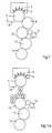
- the inking unit shown in Fig. 1 includes an ink jet printing apparatus 2 with a plurality of paint nozzles 4, which are shown schematically as arrows, which indicate the spray direction.
- the color nozzles 4 are two-dimensional Arranged matrix that nestles against an ink transfer roller 6 with a small gap in between.
- the ink transfer roller 6 rolls on an inking roller 8, which in turn opens rolls off a plate cylinder 10 of an offset printing machine, of which in FIG. 1 a rubber cylinder 12 and an impression cylinder 14 can also be seen. Alles these rollers and cylinders are single-turn, i.e. they are all the same diameter.
- dampening unit 16 for wet offset is shown schematically in FIG. 1, this is not necessary in the case of waterless offset printing.
- an ink doctor blade 18 Adjacent to the ink transfer roller 6, an ink doctor blade 18 is arranged against the ink transfer roller 6 and away from it.
- the color nozzles 4 in accordance with raster data that the Inkjet printing apparatus 2 are supplied, selectively driven to the Ink transfer roller 6 according to the raster data with printing ink spray.
- Each point on the ink transfer roller 6 is just as much Color supplied as required on the plate cylinder 10.
- the platesetter are fed Raster data, which represent the printed image, into one of the matrix Color nozzles 4 corresponding raster image converted with the inkjet printing apparatus 2 is controlled.
- the ink nozzles 4 guide the ink transfer roller 6 exactly the amount of color at each point as it was when printing from Plate cylinder 10 is delivered to the paper or other printing substrate.
- the nips between the ink transfer roller 6 and the ink application roller 8 or between the inking roller 8 and the plate cylinder 10 ensure a smooth color film so that the resolution of the ink jet printing apparatus 2nd becomes invisible.
- a raster image suitable for the ink jet printing apparatus 2 normally has a much lower resolution than the normal offset resolution because the distance of the Color nozzles 4 is comparatively large. This does not affect the print quality deteriorated, since it is ultimately determined by the plate cylinder 10, but improved, since reliably no stenciling occurs.
- color nozzles 4 In the case of a rough subject, one or in areas with little variation Subjects several color nozzles 4 can be controlled together. With fine Representations, the color nozzles 4 are individually controlled, and for coarse or full-area representations, the color nozzles 4 are controlled together.
- To control the total amount of ink applied to the ink transfer roller 6 can use sensors to record the remaining ink on the inking roller 8 can be provided, or it will be with a slight excess of color worked, from time to time with the squeegee 18 a neutral situation will be produced.
- Figure 1a shows a known from conventional inking units Ink roller arrangement to an ink jet printing apparatus 2 with a plurality of color nozzles 4 is arranged.
- Color nozzles 4 arranged in a two-dimensional matrix.
- the Two-dimensional arrangement of the color nozzles 4 has the advantage that with many small blobs of paint an almost film-like application of paint on a Ink transfer roller 6 can be applied. This makes rubbing like it is necessary in conventional inking units because one of the Ink lifter applied to a paint roller in the circumferential direction must be equalized, not necessary.
- Offset printing presses have an advantage in this because there Vibration excitation due to lateral rubbing is particularly negative affect the print quality.
- the number of ink transfer rollers 6 can thereby be reduced to a minimum.
- Fig. 2 shows a partial view of an inking unit, which in the not shown Share just as the inking unit of Fig. 1 is designed.
- the inking unit of Fig. 2 differs from that of Fig. 1 in that instead of the ink transfer roller 6 an ink transfer ribbon 20 e.g. made of steel or rubber is that rotates around two rollers 22, 24.
- the ink transfer ribbon 20 has the same circumference as the plate cylinder 10.
- the ink jet printing apparatus 2 ' is arranged, the Color nozzles 4 'are arranged in one plane in this case, whereby the Ink jet printing apparatus 2 'is easier to manufacture.
- Fig. 2 is a similar to the squeegee 18 of Fig. 1 squeegee 18 'not on the Ink transfer device, the belt 20, but on the inking roller 8th arranged.
- the inking units shown in FIGS. 1 and 2 make it possible to supply the ink to influence selected areas without the risk of stenciling exists because the single-speed design of the rollers or the belt leads to that an exposure in one place in the form of more or less color directly at the same place in the settlement and nowhere else.
- Phase shift takes place in such a way that this is due to the settlement on the provided place on the plate cylinder 10.
- the ink job from the inkjet printing apparatus then advantageously takes place 2.2 'on an ink transfer roller 6 and then directly on the plate cylinder 10 instead.
- a particularly useful way for zone-free color control 3 illustrates both in the width direction and in the circumferential direction shows a computer screen 26 on which a currently printed subject 28 is shown.
- the computer screen 26 shows that for the Platesetter used raster image of subject 28.
- the machine operator recognizes from a fresh print copy, that in a dashed area on the subject 28 an adjustment
- the ink supply is required, it can be done with the mouse or another Show device a corresponding field 30 on the computer screen 26 raise. Dragging on a corner or on an edge of the dashed line drawn field 30 with the mouse increases or decreases the field as it is known from image processing programs.
- the operator After the operator determines the exact size and position of field 30 he can do it through a suitable action such as a double click with the Select the mouse and a window for color adjustment opens (not ) in which the desired correction is specified according to strength and direction can be. In this or similar manner, the operator can quickly and easily simply correct the ink supply in any area of the subject 28.
- a suitable action such as a double click with the Select the mouse and a window for color adjustment opens (not ) in which the desired correction is specified according to strength and direction can be.
- the method of color correction illustrated in FIG. 3 is only an example and can be modified in many ways.
Landscapes
- Inking, Control Or Cleaning Of Printing Machines (AREA)
- Ink Jet (AREA)
Description
- Fig. 1
- ein Farbwerk für eine Offsetdruckmaschine, das einen Tintenstrahl-Druckapparat enthält,
- Fig. 1a
- zeigt ein konventionelles Farbwerk das einen Tintenstrahl-Druckapparat enthält.
- Fig. 2
- eine Teilansicht einer alternativen Ausführungsform des Farbwerkes, und
- Fig. 3
- einen Computerbildschirm zur Anzeige eines Drucksujets zur Beeinflussung der Farbzufuhr in ausgewählten Bereichen des Sujets.
- 2, 2'
- Tintenstrahl-Druckapparat
- 4, 4'
- Farbdüsen
- 6
- Farbübertragwalze
- 8
- Farbauftragwalze
- 10
- Plattenzylinder
- 12
- Gummizylinder
- 14
- Druckzylinder
- 16
- Feuchtwerk
- 18, 18'
- Farbrakel
- 20
- Farbübertragband
- 22, 24
- Walzen
- 26
- Computerbildschirm
- 28
- Sujet
- 30
- Feld auf dem Computerbildschirm
Claims (12)
- Farbwerk für eine Druckmaschine, das mindestens eine auf einem Plattenzylinder der Druckmaschine abrollende Farbwalze, einen Tintenstrahl-Druckapparat mit einer Vielzahl von selektiv ansteuerbaren Farbdüsen und eine Farbübetrageinrichtung mit einer umlaufenden Mantelfläche zur Übertragung von Druckfarbe vom Tintenstrahl-Druckapparat auf die mindestens eine Farbwalze enthält, dadurch gekennzeichnet, daß die mindestens eine Farbwalze (8) und die Farbübertrageinrichtung (6; 20) den gleichen Außenumfang wie der Plattenzylinder (10) haben.
- Farbwerk nach Anspruch 1, dadurch gekennzeichnet, daß die Druckmaschine eine Offsetdruckmaschine ist und daß der Rasterabstand der Farbdüsen (4; 4') kleiner als die Bildauflösung der Offsetdruckmaschine ist.
- Farbwerk nach Anspruch 1 oder 2, dadurch gekennzeichnet, daß die Druckmaschine eine Plattenbebilderungseinheit enthält und daß die vor dem Druckbetrieb für die Plattenbebilderungseinheit verwendeten Rasterdaten im Druckbetrieb zur Ansteuerung des Tintenstrahl-Druckapparates (2; 2') in jedem Maschinentakt verwendet werden.
- Farbwerk nach Anspruch 2 und Anspruch 3, dadurch gekennzeichnet, daß die für die Plattenbebilderungseinheit verwendeten Rasterdaten einer Einrichtung zum Verkleinern der Bildauflösung zugeführt werden, die entsprechende Rasterdaten mit kleinerer Bildauflösung erzeugt und den Tintenstrahl-Druckapparat (2; 2') damit ansteuert.
- Farbwerk nach einem der vorhergehenden Ansprüche, dadurch gekennzeichnet, daß die Farbübertrageinrichtung eine Farbübertragwalze (6) ist.
- Farbwerk nach einem der Ansprüche 1 bis 4, dadurch gekennzeichnet, daß die Farbübertrageinrichtung ein Farbübertragband (20) ist und daß die Farbdüsen (4') des Tintenstrahl-Druckapparates (2') in einer zu einem geradlinigen Abschnitt des Farbübertragbandes parallelen Ebene verteilt angeordnet sind.
- Farbwerk nach einem der vorhergehenden Ansprüche, dadurch gekennzeichnet, daß mindestens eine der Farbwalzen (8) und/oder die Farbübertrageinrichtung (6; 20) mit einem Antrieb für eine Hin- und Herbewegung entlang ihrer Achse während des Druckbetriebs versehen ist.
- Farbwerk nach einem der vorhergehenden Ansprüche, dadurch gekennzeichnet, daß an mindestens einer der Farbwalzen (8) und/oder der Farbübertrageinrichtung (6; 20) eine wahlweise aktivierbare Farbrakel (18; 18') vorgesehen ist.
- Farbwerk nach einem der vorhergehenden Ansprüche, dadurch gekennzeichnet, daß sich zwischen der Farbübertrageinrichtung (6; 20) und dem Plattenzylinder (10) genau eine Farbwalze (8) befindet.
- Farbwerk nach einem der vorhergehenden Ansprüche, dadurch gekennzeichnet, daß eine Steuereinrichtung zur Beeinflussung der Farbzufuhr durch einen Bediener vorgesehen ist, die einen Bildschirm (26) zur Anzeige des aktuellen Drucksujets (28) enthält, wobei zu beeinflussende Felder (30) auf dem angezeigten Drucksujet durch den Bediener auswählbar sind.
- Farbwerk nach einem der vorhergehenden Ansprüche, dadurch gekennzeichnet, daß der Tintenstrahl-Druckapparat (2, 2') eine Hochdruck-Pumpvorrichtung zur Versorgung mit Druckfarbe unter einem vorbestimmten hohen Druck, eine Heizvorrichtung zur Erwärmung der Druckfarbe auf eine vorbestimmte Temperatur oberhalb der Raumtemperatur und eine Vielzahl von Ventilen zur selektiven Steuerung der Farbzufuhr an die Farbdüsen (4; 4') des Tintenstrahl-Druckapparates enthält.
- Farbwerk nach Anspruch 11, dadurch gekennzeichnet, daß die Ventile piezoelektrisch betätigte Ventile sind.
Applications Claiming Priority (2)
| Application Number | Priority Date | Filing Date | Title |
|---|---|---|---|
| DE19859437 | 1998-12-22 | ||
| DE19859437A DE19859437A1 (de) | 1998-12-22 | 1998-12-22 | Farbwerk |
Publications (2)
| Publication Number | Publication Date |
|---|---|
| EP1013418A1 EP1013418A1 (de) | 2000-06-28 |
| EP1013418B1 true EP1013418B1 (de) | 2003-09-17 |
Family
ID=7892246
Family Applications (1)
| Application Number | Title | Priority Date | Filing Date |
|---|---|---|---|
| EP99125079A Expired - Lifetime EP1013418B1 (de) | 1998-12-22 | 1999-12-16 | Farbwerk |
Country Status (5)
| Country | Link |
|---|---|
| US (1) | US6427591B1 (de) |
| EP (1) | EP1013418B1 (de) |
| JP (1) | JP4402229B2 (de) |
| DE (2) | DE19859437A1 (de) |
| IL (1) | IL133620A (de) |
Families Citing this family (17)
| Publication number | Priority date | Publication date | Assignee | Title |
|---|---|---|---|---|
| US6748860B2 (en) * | 1994-04-15 | 2004-06-15 | Heidelberger Druckmaschinen Ag | Operating panel for a printing machine, inking control system for a printing machine, and inking control method |
| JP4279516B2 (ja) * | 2002-07-01 | 2009-06-17 | 大日本スクリーン製造株式会社 | 印刷機 |
| US7080901B2 (en) * | 2002-12-03 | 2006-07-25 | Dai Nippon Printing Co. Ltd. | Printing unit and manufacturing line for manufacturing flexible organic EL display |
| KR101228025B1 (ko) * | 2004-01-15 | 2013-01-30 | 케이비에이-노타시스 에스에이 | 음각 인쇄기용 잉킹 시스템 |
| DE102005021186B4 (de) | 2004-05-03 | 2024-05-08 | manroland sheetfed GmbH | Einrichtung und Verfahren zum Erzeugen einer Beschichtung von Druckprodukten einer Druckmaschine |
| US7517076B2 (en) * | 2004-06-30 | 2009-04-14 | Eastman Kodak Company | Phase-change ink jet printing with electrostatic transfer |
| JP4526340B2 (ja) * | 2004-09-15 | 2010-08-18 | 大日本印刷株式会社 | 凸版印刷装置 |
| DE102005062897A1 (de) * | 2005-04-02 | 2006-10-05 | Koenig & Bauer Ag | Druckmaschine mit mindestens einem Druckwerk |
| DE102005024007B4 (de) * | 2005-05-25 | 2008-05-29 | Koenig & Bauer Aktiengesellschaft | Druckwerk mit Farbwerk zum Auftragen von Druckfarbe auf einen Formzylinder einer Druckmaschine |
| US20070068404A1 (en) * | 2005-09-29 | 2007-03-29 | Edwin Hirahara | Systems and methods for additive deposition of materials onto a substrate |
| DE102006053622A1 (de) * | 2006-11-14 | 2008-05-15 | Impress Decor Gmbh | Verfahren und Vorrichtung zum Digitaldruck auf einen saugfähigen Bedruckstoff |
| FR2909304B1 (fr) * | 2006-12-05 | 2009-03-27 | Sidel Participations | Procede de fabrication de recipients avec retroaction en fonction du point de debut de presoufflage |
| DE102008026885A1 (de) | 2007-06-26 | 2009-01-02 | Heidelberger Druckmaschinen Ag | Vorrichtung zum Dosieren drucktechnischer Flüssigkeit |
| DE102007059915A1 (de) * | 2007-12-12 | 2009-06-18 | Koenig & Bauer Aktiengesellschaft | Vorrichtung und Verfahren zum Beschichten von Bedruckstoffen in einer Rotationsdruckmaschine |
| DE202013102257U1 (de) * | 2012-05-29 | 2013-06-12 | manroland sheetfed GmbH | Inkjet-Druckkopf in einer Druckmaschine |
| DE102013215267A1 (de) * | 2013-08-02 | 2015-02-05 | Windmöller & Hölscher Kg | Dosierwerk |
| CN113910753B (zh) * | 2021-10-11 | 2023-06-23 | 邵东市湘泰彩印包装有限公司 | 一种针对不同型号塑料袋印刷的凹版印刷机 |
Family Cites Families (16)
| Publication number | Priority date | Publication date | Assignee | Title |
|---|---|---|---|---|
| GB1230020A (de) * | 1967-06-30 | 1971-04-28 | ||
| DE3329331C2 (de) * | 1983-08-13 | 1987-02-26 | Heidelberger Druckmaschinen Ag, 6900 Heidelberg | Druckwerk mit kurzem Farbwerk |
| DE3687074D1 (de) * | 1985-03-21 | 1992-12-17 | Felix Brunner | Verfahren, regelvorrichtung und hilfsmittel zur erzielung eines gleichfoermigen druckresultats an einer autotypisch arbeitenden mehrfarbenoffsetdruckmaschine. |
| DE3545535A1 (de) * | 1985-12-21 | 1987-07-02 | Mailaender Fa J G | Verfahren zum auftragen von feuchtmittel und/oder farbe auf eine offset-druckform und vorrichtung zur durchfuehrung des verfahrens |
| US4787313A (en) * | 1986-04-29 | 1988-11-29 | Didde Graphic Systems Corporation | Printing press using shiftable inking means |
| DE3826385A1 (de) * | 1988-08-03 | 1990-02-08 | Roland Man Druckmasch | Vorrichtung zum auswerten von druckvorlagen |
| JP3223927B2 (ja) * | 1991-08-23 | 2001-10-29 | セイコーエプソン株式会社 | 転写式記録装置 |
| DE4220177A1 (de) | 1992-06-19 | 1993-12-23 | Marco Systemanalyse Entw | Vorrichtung zur Betätigung eines Ventilelementes |
| DE4301950A1 (de) * | 1993-01-25 | 1994-07-28 | Koenig & Bauer Ag | Verfahren und Vorrichtung zum Verhindern eines Niederschlages eines unerwünschten aerosolartigen Mediums in einer Rotationsdruckmaschine |
| DE4327212A1 (de) * | 1993-08-13 | 1995-02-16 | Heidelberger Druckmasch Ag | Verfahren und Vorrichtung zur Farbübertragung im Druckwerk einer Offsetdruckmaschine |
| DE19745136B4 (de) * | 1996-10-17 | 2007-07-12 | Heidelberger Druckmaschinen Ag | Rotationsbogendruckmaschine |
| DE19704003A1 (de) * | 1997-02-04 | 1998-08-06 | Kba Planeta Ag | Verfahren und Vorrichtung zum Eindrucken von individualisierenden Kennzeichnungen |
| JPH10264351A (ja) * | 1997-03-28 | 1998-10-06 | Riso Kagaku Corp | 複式印刷装置及び複式印刷装置における記録方法 |
| DE19743770A1 (de) * | 1997-10-02 | 1999-04-08 | Heidelberger Druckmasch Ag | Verfahren zum Betrieb einer Rotationsdruckmaschine und Vorrichtung zur Durchführung des Verfahrens |
| JPH11139016A (ja) * | 1997-11-14 | 1999-05-25 | Hitachi Koki Co Ltd | ソリッドインク印刷原版及びその作製方法 |
| US5980136A (en) * | 1998-04-23 | 1999-11-09 | Xerox Corporation | Drum platen type printing machine for printing on regular and card-stock substrates |
-
1998
- 1998-12-22 DE DE19859437A patent/DE19859437A1/de not_active Withdrawn
-
1999
- 1999-12-16 EP EP99125079A patent/EP1013418B1/de not_active Expired - Lifetime
- 1999-12-16 DE DE59907008T patent/DE59907008D1/de not_active Expired - Lifetime
- 1999-12-20 IL IL13362099A patent/IL133620A/xx active IP Right Grant
- 1999-12-21 JP JP36268999A patent/JP4402229B2/ja not_active Expired - Fee Related
- 1999-12-22 US US09/470,891 patent/US6427591B1/en not_active Expired - Fee Related
Also Published As
| Publication number | Publication date |
|---|---|
| DE59907008D1 (de) | 2003-10-23 |
| DE19859437A1 (de) | 2000-06-29 |
| US6427591B1 (en) | 2002-08-06 |
| EP1013418A1 (de) | 2000-06-28 |
| JP4402229B2 (ja) | 2010-01-20 |
| JP2000185391A (ja) | 2000-07-04 |
| IL133620A (en) | 2003-06-24 |
| IL133620A0 (en) | 2001-04-30 |
Similar Documents
| Publication | Publication Date | Title |
|---|---|---|
| EP1013418B1 (de) | Farbwerk | |
| DE69826545T2 (de) | Druckmaschine mit auswechselbarer Vorrichtung zum Aufbringen von Farbe | |
| EP0141168B1 (de) | Farbwerksvoreinstellung | |
| DE19720954C2 (de) | Verfahren zum Einrichten der Farbführung im Fortdruck in einer Rotationsdruckmaschine | |
| EP1243414B1 (de) | Druckverfahren | |
| EP2703162B1 (de) | Verfahren und Vorrichtung zum Bedrucken von Bedruckstoff | |
| CH694582A5 (de) | Kurzfarbwerk. | |
| DE2259085A1 (de) | Farbwerk fuer flachdruckmaschinen | |
| DE19921628A1 (de) | Verfahren zum Dosieren von Feuchtmittel beim Drucken mit einer Druckform für Offsetdruck | |
| EP3658379B1 (de) | Vorrichtung zum beschichten von nutzen, eine druckmaschine und verfahren zum beschichten von nutzen | |
| DE19934395A1 (de) | Farbwerk in einer Rotations-Offsetdruckmaschine mit einer Farbauftragswalze zur Verringerung des Perleffekts der Druckfarbe | |
| DE3714160A1 (de) | Farbwerk fuer eine druckmaschine | |
| EP0761432B2 (de) | Feuchtwerk für eine Offsetdruckmaschine | |
| DE3034588C2 (de) | Offset-Rotationsdruckmaschine mit einer Einrichtung zur Unterbrechung der Feuchtmittelzufuhr | |
| DE102010034350A1 (de) | Einrichtung zur Regelung des Feuchtmittelauftrags und Farbauftrags in einer Druckmaschine | |
| EP0941847A1 (de) | Einrichtung und Verfahren für das Dosieren von Farbe in Offsetdruckmaschinen | |
| DE3906647A1 (de) | Kurzfarbwerk | |
| DE102005013634A1 (de) | Verfahren zum Betrieb einer Druckmaschine | |
| EP1752287B1 (de) | Bogendruckmaschine und -verfahren | |
| EP1149696B1 (de) | Offsetdruckwerk für eine Druckmaschine | |
| DE3011031C2 (de) | Bogen-Rotations-Andruckoffsetdruckmaschine | |
| DE29807277U1 (de) | Steuerung für ein Heberfarbwerk einer Druckmaschine | |
| DE10325185B4 (de) | Verfahren zum Betrieb eines Druckwerks einer Druckmaschine in Abhängigkeit von der Farbtemperatur sowie nach dem Verfahren arbeitende Druckmaschinensteuerung | |
| EP1911581A2 (de) | Farbdosiereinrichtung für ein Farbwerk | |
| EP2090431B1 (de) | Verfahren und Vorrichtung zur Steuerung eines Feuchtwerkes einer Rotationsflachdruckmaschine |
Legal Events
| Date | Code | Title | Description |
|---|---|---|---|
| PUAI | Public reference made under article 153(3) epc to a published international application that has entered the european phase |
Free format text: ORIGINAL CODE: 0009012 |
|
| 17P | Request for examination filed |
Effective date: 20000415 |
|
| AK | Designated contracting states |
Kind code of ref document: A1 Designated state(s): AT BE CH CY DE DK ES FI FR GB GR IE IT LI LU MC NL PT SE |
|
| AX | Request for extension of the european patent |
Free format text: AL;LT;LV;MK;RO;SI |
|
| AKX | Designation fees paid |
Free format text: AT BE CH CY DE DK ES FI FR GB GR IE IT LI LU MC NL PT SE |
|
| GRAH | Despatch of communication of intention to grant a patent |
Free format text: ORIGINAL CODE: EPIDOS IGRA |
|
| RBV | Designated contracting states (corrected) |
Designated state(s): BE CH DE FR GB IT LI NL |
|
| GRAH | Despatch of communication of intention to grant a patent |
Free format text: ORIGINAL CODE: EPIDOS IGRA |
|
| GRAA | (expected) grant |
Free format text: ORIGINAL CODE: 0009210 |
|
| AK | Designated contracting states |
Kind code of ref document: B1 Designated state(s): BE CH DE FR GB IT LI NL |
|
| PG25 | Lapsed in a contracting state [announced via postgrant information from national office to epo] |
Ref country code: NL Free format text: LAPSE BECAUSE OF FAILURE TO SUBMIT A TRANSLATION OF THE DESCRIPTION OR TO PAY THE FEE WITHIN THE PRESCRIBED TIME-LIMIT Effective date: 20030917 Ref country code: IT Free format text: LAPSE BECAUSE OF FAILURE TO SUBMIT A TRANSLATION OF THE DESCRIPTION OR TO PAY THE FEE WITHIN THE PRESCRIBED TIME-LIMIT;WARNING: LAPSES OF ITALIAN PATENTS WITH EFFECTIVE DATE BEFORE 2007 MAY HAVE OCCURRED AT ANY TIME BEFORE 2007. THE CORRECT EFFECTIVE DATE MAY BE DIFFERENT FROM THE ONE RECORDED. Effective date: 20030917 |
|
| REG | Reference to a national code |
Ref country code: GB Ref legal event code: FG4D Free format text: NOT ENGLISH |
|
| REG | Reference to a national code |
Ref country code: CH Ref legal event code: EP |
|
| REF | Corresponds to: |
Ref document number: 59907008 Country of ref document: DE Date of ref document: 20031023 Kind code of ref document: P |
|
| REG | Reference to a national code |
Ref country code: IE Ref legal event code: FG4D Free format text: GERMAN |
|
| GBT | Gb: translation of ep patent filed (gb section 77(6)(a)/1977) |
Effective date: 20031112 |
|
| PG25 | Lapsed in a contracting state [announced via postgrant information from national office to epo] |
Ref country code: LI Free format text: LAPSE BECAUSE OF NON-PAYMENT OF DUE FEES Effective date: 20031231 Ref country code: CH Free format text: LAPSE BECAUSE OF NON-PAYMENT OF DUE FEES Effective date: 20031231 Ref country code: BE Free format text: LAPSE BECAUSE OF NON-PAYMENT OF DUE FEES Effective date: 20031231 |
|
| NLV1 | Nl: lapsed or annulled due to failure to fulfill the requirements of art. 29p and 29m of the patents act | ||
| REG | Reference to a national code |
Ref country code: IE Ref legal event code: FD4D |
|
| BERE | Be: lapsed |
Owner name: *HEIDELBERGER DRUCKMASCHINEN A.G. Effective date: 20031231 |
|
| ET | Fr: translation filed | ||
| PLBE | No opposition filed within time limit |
Free format text: ORIGINAL CODE: 0009261 |
|
| STAA | Information on the status of an ep patent application or granted ep patent |
Free format text: STATUS: NO OPPOSITION FILED WITHIN TIME LIMIT |
|
| REG | Reference to a national code |
Ref country code: CH Ref legal event code: PL |
|
| 26N | No opposition filed |
Effective date: 20040618 |
|
| PGFP | Annual fee paid to national office [announced via postgrant information from national office to epo] |
Ref country code: GB Payment date: 20041122 Year of fee payment: 6 |
|
| PG25 | Lapsed in a contracting state [announced via postgrant information from national office to epo] |
Ref country code: GB Free format text: LAPSE BECAUSE OF NON-PAYMENT OF DUE FEES Effective date: 20051216 |
|
| GBPC | Gb: european patent ceased through non-payment of renewal fee |
Effective date: 20051216 |
|
| PGFP | Annual fee paid to national office [announced via postgrant information from national office to epo] |
Ref country code: DE Payment date: 20121231 Year of fee payment: 14 Ref country code: FR Payment date: 20130117 Year of fee payment: 14 |
|
| REG | Reference to a national code |
Ref country code: DE Ref legal event code: R119 Ref document number: 59907008 Country of ref document: DE |
|
| REG | Reference to a national code |
Ref country code: DE Ref legal event code: R119 Ref document number: 59907008 Country of ref document: DE Effective date: 20140701 |
|
| REG | Reference to a national code |
Ref country code: FR Ref legal event code: ST Effective date: 20140829 |
|
| PG25 | Lapsed in a contracting state [announced via postgrant information from national office to epo] |
Ref country code: DE Free format text: LAPSE BECAUSE OF NON-PAYMENT OF DUE FEES Effective date: 20140701 |
|
| PG25 | Lapsed in a contracting state [announced via postgrant information from national office to epo] |
Ref country code: FR Free format text: LAPSE BECAUSE OF NON-PAYMENT OF DUE FEES Effective date: 20131231 |