EP1011889B1 - Articles pour la fabrication d'extenseurs et procedes associes - Google Patents
Articles pour la fabrication d'extenseurs et procedes associes Download PDFInfo
- Publication number
- EP1011889B1 EP1011889B1 EP97906450A EP97906450A EP1011889B1 EP 1011889 B1 EP1011889 B1 EP 1011889B1 EP 97906450 A EP97906450 A EP 97906450A EP 97906450 A EP97906450 A EP 97906450A EP 1011889 B1 EP1011889 B1 EP 1011889B1
- Authority
- EP
- European Patent Office
- Prior art keywords
- annular
- lattice
- planar
- stent
- radially
- Prior art date
- Legal status (The legal status is an assumption and is not a legal conclusion. Google has not performed a legal analysis and makes no representation as to the accuracy of the status listed.)
- Expired - Lifetime
Links
Images


Classifications
-
- A—HUMAN NECESSITIES
- A61—MEDICAL OR VETERINARY SCIENCE; HYGIENE
- A61F—FILTERS IMPLANTABLE INTO BLOOD VESSELS; PROSTHESES; DEVICES PROVIDING PATENCY TO, OR PREVENTING COLLAPSING OF, TUBULAR STRUCTURES OF THE BODY, e.g. STENTS; ORTHOPAEDIC, NURSING OR CONTRACEPTIVE DEVICES; FOMENTATION; TREATMENT OR PROTECTION OF EYES OR EARS; BANDAGES, DRESSINGS OR ABSORBENT PADS; FIRST-AID KITS
- A61F2/00—Filters implantable into blood vessels; Prostheses, i.e. artificial substitutes or replacements for parts of the body; Appliances for connecting them with the body; Devices providing patency to, or preventing collapsing of, tubular structures of the body, e.g. stents
- A61F2/82—Devices providing patency to, or preventing collapsing of, tubular structures of the body, e.g. stents
- A61F2/86—Stents in a form characterised by the wire-like elements; Stents in the form characterised by a net-like or mesh-like structure
- A61F2/88—Stents in a form characterised by the wire-like elements; Stents in the form characterised by a net-like or mesh-like structure the wire-like elements formed as helical or spiral coils
-
- A—HUMAN NECESSITIES
- A61—MEDICAL OR VETERINARY SCIENCE; HYGIENE
- A61F—FILTERS IMPLANTABLE INTO BLOOD VESSELS; PROSTHESES; DEVICES PROVIDING PATENCY TO, OR PREVENTING COLLAPSING OF, TUBULAR STRUCTURES OF THE BODY, e.g. STENTS; ORTHOPAEDIC, NURSING OR CONTRACEPTIVE DEVICES; FOMENTATION; TREATMENT OR PROTECTION OF EYES OR EARS; BANDAGES, DRESSINGS OR ABSORBENT PADS; FIRST-AID KITS
- A61F2/00—Filters implantable into blood vessels; Prostheses, i.e. artificial substitutes or replacements for parts of the body; Appliances for connecting them with the body; Devices providing patency to, or preventing collapsing of, tubular structures of the body, e.g. stents
- A61F2/82—Devices providing patency to, or preventing collapsing of, tubular structures of the body, e.g. stents
- A61F2/86—Stents in a form characterised by the wire-like elements; Stents in the form characterised by a net-like or mesh-like structure
- A61F2/90—Stents in a form characterised by the wire-like elements; Stents in the form characterised by a net-like or mesh-like structure characterised by a net-like or mesh-like structure
- A61F2/91—Stents in a form characterised by the wire-like elements; Stents in the form characterised by a net-like or mesh-like structure characterised by a net-like or mesh-like structure made from perforated sheet material or tubes, e.g. perforated by laser cuts or etched holes
- A61F2/915—Stents in a form characterised by the wire-like elements; Stents in the form characterised by a net-like or mesh-like structure characterised by a net-like or mesh-like structure made from perforated sheet material or tubes, e.g. perforated by laser cuts or etched holes with bands having a meander structure, adjacent bands being connected to each other
-
- B—PERFORMING OPERATIONS; TRANSPORTING
- B21—MECHANICAL METAL-WORKING WITHOUT ESSENTIALLY REMOVING MATERIAL; PUNCHING METAL
- B21D—WORKING OR PROCESSING OF SHEET METAL OR METAL TUBES, RODS OR PROFILES WITHOUT ESSENTIALLY REMOVING MATERIAL; PUNCHING METAL
- B21D51/00—Making hollow objects
- B21D51/02—Making hollow objects characterised by the structure of the objects
- B21D51/10—Making hollow objects characterised by the structure of the objects conically or cylindrically shaped objects
-
- A—HUMAN NECESSITIES
- A61—MEDICAL OR VETERINARY SCIENCE; HYGIENE
- A61F—FILTERS IMPLANTABLE INTO BLOOD VESSELS; PROSTHESES; DEVICES PROVIDING PATENCY TO, OR PREVENTING COLLAPSING OF, TUBULAR STRUCTURES OF THE BODY, e.g. STENTS; ORTHOPAEDIC, NURSING OR CONTRACEPTIVE DEVICES; FOMENTATION; TREATMENT OR PROTECTION OF EYES OR EARS; BANDAGES, DRESSINGS OR ABSORBENT PADS; FIRST-AID KITS
- A61F2/00—Filters implantable into blood vessels; Prostheses, i.e. artificial substitutes or replacements for parts of the body; Appliances for connecting them with the body; Devices providing patency to, or preventing collapsing of, tubular structures of the body, e.g. stents
- A61F2/82—Devices providing patency to, or preventing collapsing of, tubular structures of the body, e.g. stents
- A61F2/86—Stents in a form characterised by the wire-like elements; Stents in the form characterised by a net-like or mesh-like structure
- A61F2/90—Stents in a form characterised by the wire-like elements; Stents in the form characterised by a net-like or mesh-like structure characterised by a net-like or mesh-like structure
- A61F2/91—Stents in a form characterised by the wire-like elements; Stents in the form characterised by a net-like or mesh-like structure characterised by a net-like or mesh-like structure made from perforated sheet material or tubes, e.g. perforated by laser cuts or etched holes
- A61F2/915—Stents in a form characterised by the wire-like elements; Stents in the form characterised by a net-like or mesh-like structure characterised by a net-like or mesh-like structure made from perforated sheet material or tubes, e.g. perforated by laser cuts or etched holes with bands having a meander structure, adjacent bands being connected to each other
- A61F2002/91533—Stents in a form characterised by the wire-like elements; Stents in the form characterised by a net-like or mesh-like structure characterised by a net-like or mesh-like structure made from perforated sheet material or tubes, e.g. perforated by laser cuts or etched holes with bands having a meander structure, adjacent bands being connected to each other characterised by the phase between adjacent bands
-
- A—HUMAN NECESSITIES
- A61—MEDICAL OR VETERINARY SCIENCE; HYGIENE
- A61F—FILTERS IMPLANTABLE INTO BLOOD VESSELS; PROSTHESES; DEVICES PROVIDING PATENCY TO, OR PREVENTING COLLAPSING OF, TUBULAR STRUCTURES OF THE BODY, e.g. STENTS; ORTHOPAEDIC, NURSING OR CONTRACEPTIVE DEVICES; FOMENTATION; TREATMENT OR PROTECTION OF EYES OR EARS; BANDAGES, DRESSINGS OR ABSORBENT PADS; FIRST-AID KITS
- A61F2/00—Filters implantable into blood vessels; Prostheses, i.e. artificial substitutes or replacements for parts of the body; Appliances for connecting them with the body; Devices providing patency to, or preventing collapsing of, tubular structures of the body, e.g. stents
- A61F2/82—Devices providing patency to, or preventing collapsing of, tubular structures of the body, e.g. stents
- A61F2/86—Stents in a form characterised by the wire-like elements; Stents in the form characterised by a net-like or mesh-like structure
- A61F2/90—Stents in a form characterised by the wire-like elements; Stents in the form characterised by a net-like or mesh-like structure characterised by a net-like or mesh-like structure
- A61F2/91—Stents in a form characterised by the wire-like elements; Stents in the form characterised by a net-like or mesh-like structure characterised by a net-like or mesh-like structure made from perforated sheet material or tubes, e.g. perforated by laser cuts or etched holes
- A61F2/915—Stents in a form characterised by the wire-like elements; Stents in the form characterised by a net-like or mesh-like structure characterised by a net-like or mesh-like structure made from perforated sheet material or tubes, e.g. perforated by laser cuts or etched holes with bands having a meander structure, adjacent bands being connected to each other
- A61F2002/9155—Adjacent bands being connected to each other
- A61F2002/91558—Adjacent bands being connected to each other connected peak to peak
-
- A—HUMAN NECESSITIES
- A61—MEDICAL OR VETERINARY SCIENCE; HYGIENE
- A61F—FILTERS IMPLANTABLE INTO BLOOD VESSELS; PROSTHESES; DEVICES PROVIDING PATENCY TO, OR PREVENTING COLLAPSING OF, TUBULAR STRUCTURES OF THE BODY, e.g. STENTS; ORTHOPAEDIC, NURSING OR CONTRACEPTIVE DEVICES; FOMENTATION; TREATMENT OR PROTECTION OF EYES OR EARS; BANDAGES, DRESSINGS OR ABSORBENT PADS; FIRST-AID KITS
- A61F2230/00—Geometry of prostheses classified in groups A61F2/00 - A61F2/26 or A61F2/82 or A61F9/00 or A61F11/00 or subgroups thereof
- A61F2230/0002—Two-dimensional shapes, e.g. cross-sections
- A61F2230/0017—Angular shapes
-
- A—HUMAN NECESSITIES
- A61—MEDICAL OR VETERINARY SCIENCE; HYGIENE
- A61F—FILTERS IMPLANTABLE INTO BLOOD VESSELS; PROSTHESES; DEVICES PROVIDING PATENCY TO, OR PREVENTING COLLAPSING OF, TUBULAR STRUCTURES OF THE BODY, e.g. STENTS; ORTHOPAEDIC, NURSING OR CONTRACEPTIVE DEVICES; FOMENTATION; TREATMENT OR PROTECTION OF EYES OR EARS; BANDAGES, DRESSINGS OR ABSORBENT PADS; FIRST-AID KITS
- A61F2230/00—Geometry of prostheses classified in groups A61F2/00 - A61F2/26 or A61F2/82 or A61F9/00 or A61F11/00 or subgroups thereof
- A61F2230/0002—Two-dimensional shapes, e.g. cross-sections
- A61F2230/0028—Shapes in the form of latin or greek characters
- A61F2230/005—Rosette-shaped, e.g. star-shaped
-
- A—HUMAN NECESSITIES
- A61—MEDICAL OR VETERINARY SCIENCE; HYGIENE
- A61F—FILTERS IMPLANTABLE INTO BLOOD VESSELS; PROSTHESES; DEVICES PROVIDING PATENCY TO, OR PREVENTING COLLAPSING OF, TUBULAR STRUCTURES OF THE BODY, e.g. STENTS; ORTHOPAEDIC, NURSING OR CONTRACEPTIVE DEVICES; FOMENTATION; TREATMENT OR PROTECTION OF EYES OR EARS; BANDAGES, DRESSINGS OR ABSORBENT PADS; FIRST-AID KITS
- A61F2230/00—Geometry of prostheses classified in groups A61F2/00 - A61F2/26 or A61F2/82 or A61F9/00 or A61F11/00 or subgroups thereof
- A61F2230/0002—Two-dimensional shapes, e.g. cross-sections
- A61F2230/0028—Shapes in the form of latin or greek characters
- A61F2230/0054—V-shaped
-
- A—HUMAN NECESSITIES
- A61—MEDICAL OR VETERINARY SCIENCE; HYGIENE
- A61F—FILTERS IMPLANTABLE INTO BLOOD VESSELS; PROSTHESES; DEVICES PROVIDING PATENCY TO, OR PREVENTING COLLAPSING OF, TUBULAR STRUCTURES OF THE BODY, e.g. STENTS; ORTHOPAEDIC, NURSING OR CONTRACEPTIVE DEVICES; FOMENTATION; TREATMENT OR PROTECTION OF EYES OR EARS; BANDAGES, DRESSINGS OR ABSORBENT PADS; FIRST-AID KITS
- A61F2230/00—Geometry of prostheses classified in groups A61F2/00 - A61F2/26 or A61F2/82 or A61F9/00 or A61F11/00 or subgroups thereof
- A61F2230/0063—Three-dimensional shapes
- A61F2230/0067—Three-dimensional shapes conical
-
- A—HUMAN NECESSITIES
- A61—MEDICAL OR VETERINARY SCIENCE; HYGIENE
- A61F—FILTERS IMPLANTABLE INTO BLOOD VESSELS; PROSTHESES; DEVICES PROVIDING PATENCY TO, OR PREVENTING COLLAPSING OF, TUBULAR STRUCTURES OF THE BODY, e.g. STENTS; ORTHOPAEDIC, NURSING OR CONTRACEPTIVE DEVICES; FOMENTATION; TREATMENT OR PROTECTION OF EYES OR EARS; BANDAGES, DRESSINGS OR ABSORBENT PADS; FIRST-AID KITS
- A61F2240/00—Manufacturing or designing of prostheses classified in groups A61F2/00 - A61F2/26 or A61F2/82 or A61F9/00 or A61F11/00 or subgroups thereof
- A61F2240/001—Designing or manufacturing processes
-
- Y—GENERAL TAGGING OF NEW TECHNOLOGICAL DEVELOPMENTS; GENERAL TAGGING OF CROSS-SECTIONAL TECHNOLOGIES SPANNING OVER SEVERAL SECTIONS OF THE IPC; TECHNICAL SUBJECTS COVERED BY FORMER USPC CROSS-REFERENCE ART COLLECTIONS [XRACs] AND DIGESTS
- Y10—TECHNICAL SUBJECTS COVERED BY FORMER USPC
- Y10S—TECHNICAL SUBJECTS COVERED BY FORMER USPC CROSS-REFERENCE ART COLLECTIONS [XRACs] AND DIGESTS
- Y10S623/00—Prosthesis, i.e. artificial body members, parts thereof, or aids and accessories therefor
- Y10S623/901—Method of manufacturing prosthetic device
-
- Y—GENERAL TAGGING OF NEW TECHNOLOGICAL DEVELOPMENTS; GENERAL TAGGING OF CROSS-SECTIONAL TECHNOLOGIES SPANNING OVER SEVERAL SECTIONS OF THE IPC; TECHNICAL SUBJECTS COVERED BY FORMER USPC CROSS-REFERENCE ART COLLECTIONS [XRACs] AND DIGESTS
- Y10—TECHNICAL SUBJECTS COVERED BY FORMER USPC
- Y10T—TECHNICAL SUBJECTS COVERED BY FORMER US CLASSIFICATION
- Y10T29/00—Metal working
- Y10T29/18—Expanded metal making
-
- Y—GENERAL TAGGING OF NEW TECHNOLOGICAL DEVELOPMENTS; GENERAL TAGGING OF CROSS-SECTIONAL TECHNOLOGIES SPANNING OVER SEVERAL SECTIONS OF THE IPC; TECHNICAL SUBJECTS COVERED BY FORMER USPC CROSS-REFERENCE ART COLLECTIONS [XRACs] AND DIGESTS
- Y10—TECHNICAL SUBJECTS COVERED BY FORMER USPC
- Y10T—TECHNICAL SUBJECTS COVERED BY FORMER US CLASSIFICATION
- Y10T29/00—Metal working
- Y10T29/49—Method of mechanical manufacture
- Y10T29/49789—Obtaining plural product pieces from unitary workpiece
-
- Y—GENERAL TAGGING OF NEW TECHNOLOGICAL DEVELOPMENTS; GENERAL TAGGING OF CROSS-SECTIONAL TECHNOLOGIES SPANNING OVER SEVERAL SECTIONS OF THE IPC; TECHNICAL SUBJECTS COVERED BY FORMER USPC CROSS-REFERENCE ART COLLECTIONS [XRACs] AND DIGESTS
- Y10—TECHNICAL SUBJECTS COVERED BY FORMER USPC
- Y10T—TECHNICAL SUBJECTS COVERED BY FORMER US CLASSIFICATION
- Y10T29/00—Metal working
- Y10T29/49—Method of mechanical manufacture
- Y10T29/49799—Providing transitory integral holding or handling portion
-
- Y—GENERAL TAGGING OF NEW TECHNOLOGICAL DEVELOPMENTS; GENERAL TAGGING OF CROSS-SECTIONAL TECHNOLOGIES SPANNING OVER SEVERAL SECTIONS OF THE IPC; TECHNICAL SUBJECTS COVERED BY FORMER USPC CROSS-REFERENCE ART COLLECTIONS [XRACs] AND DIGESTS
- Y10—TECHNICAL SUBJECTS COVERED BY FORMER USPC
- Y10T—TECHNICAL SUBJECTS COVERED BY FORMER US CLASSIFICATION
- Y10T29/00—Metal working
- Y10T29/49—Method of mechanical manufacture
- Y10T29/49995—Shaping one-piece blank by removing material
Definitions
- the present invention relates generally to stents and other prostheses intended for implantation in blood vessels and other body lumens.
- the present invention relates to a method and a planar structure for the fabrication of such stents.
- stents and other luminal prostheses are often indicated when there is desire to maintain patency of a body lumen.
- Stents have commonly been used in blood vessels, the ureter, and the biliary duct, for the treatment of conditions which can result in luminal obstruction.
- vascular stents have demonstrated significant success in inhibiting restenosis following angioplasty and other primary interventional treatments in the vasculature.
- Lined scents often referred to as vascular stent grafts or prostheses, hold great promise for the reinforcement of blood vessels for the treatment of aneurysms and lining of blood vessels for the treatment of occlusive disease among other conditions.
- the stent acts as a scaffold or framework for supporting the liner within the blood vessel to define an artificial lumen therethrough.
- the stent maintains lumenal patency while the liner inhibits cellular intrusion into the lumen.
- Vascular stents are typically delivered in a radially reduced or constrained configuration and expanded in situ at the target site.
- the stents may be deformable and balloon-expanded at the target site.
- the stents may be formed from a resilient material and released from constraint to self-expand at the target site.
- the stents are formed from a shape-memory alloy and induced to expand at the target site by exposure to a temperature change. In all such cases, the stent will usually comprise a network or lattice of structural elements which permits configuration in both the radially-reduced and the radially-expanded geometries.
- One common geometry comprises a plurality of lozenge-shaped or diamond-shaped elements which are joined in a ring and may be expanded from a small diameter configuration to a large diameter configuration.
- Other common geometries include helically wound wires and filaments, zig-zag rings, serpentine rings, and numerous combinations and derivations of these geometries.
- the stents have very small dimensions, often with diameters of 1 mm and below, and may be formed from metals and alloys that are difficult to fabricate, such as shape memory alloys and stainless steel alloys having specific properties. It will be appreciated that the stents which are produced must have highly uniform expansion characteristics, and thus the fabrications methods should result in stents having highly uniform mechanical properties. Moreover, the dimensions must meet very close tolerances and the surface finishes of the stents must be non-injurious and non-thrombogenic.
- vascular and other stents start with a tube which is then cut or otherwise patterned to have the desired geometry. In many cases, particularly with shape memory alloys, it will be further necessary to heat-treat the resulting stent in order to gain desired expansion properties.
- Cutting of the tube stock starting material can be effected in a variety of ways. Most commonly, laser cutting is employed. Laser cutting, however, results in significant thermal stresses on the material which can be particularly troublesome when producing shape memory alloy stents. Chemical etching of the tube starting materials have also been proposed. Patterning and etching of tubes, however, is very difficult and expensive to perform.
- Such improved methods should preferably be compatible with a wide variety of starting materials, including shape memory alloys, stainless steel alloys, and other materials from which stents are commonly performed. Such methods and articles, moreover, should preferably expose the materials to minimum thermal and other stresses, thus enhancing the dimensional and physical stability of the resulting stents.
- the present invention will address at least some of these objectives.
- the present invention provides improved methods for fabricating cylindrical stents from planar articles.
- the planar articles comprise networks of interconnected elements, and the methods comprise the reforming the planar networks into a cylindrical wall which may form all or part of a stent or other luminal prosthesis.
- the planar networks will comprise an annular lattice of element(s), where the lattice may be formed as a continuous path or as a discontinuous path.
- the lattice will be continuous and will comprise interconnected elements joined in a complete annular ring.
- Exemplary geometries include serpentine rings, a plurality of closed peripheral structures, such as interconnected lozenge (diamond)-shaped structures, and the like.
- Exemplary discontinuous lattices include spirals having a radially inward end and radially outward end. Such spirals may have secondary geometries, such as a superimposed serpentine pattern, and in some cases may be arranged in a rectilinear pattern (in addition to curved spiral patterns).
- the reforming step will comprise everting the annular lattice to the desired cylindrical configuration. It will be appreciated that such eversion may be effected either by expanding the inner peripheral edge, contracting the outer peripheral edge, or a combination of both such steps. Often, the everting step will be performed over the exterior surface of a cylindrical mandrel. Alternatively, the everting step could be performed by introducing the annular lattice into a cylindrical tube or lumen, or by other equivalent techniques.
- the reformed annular lattices will assume a radially expansible, typically cylindrical, configuration.
- radially expansible it is meant that width (diameter in the case of cylindrical structures) can be expanded and/or contacted after reforming.
- the structures will be either malleable, in which case they are expanded by application of a radially outward force in their lumens, or self-expanding in which case the initial geometry will be “expanded” and will be radially constrained prior to use.
- the latter type of stents are usually formed from shape memory alloys or resilient stainless steel and referred to as “self-expanding stents.”
- planar articles of the present invention may be formed in a variety of ways. Usually, they will be formed by patterning a planar sheet of material. Exemplary patterning steps include photochemical etching (usually performed as part of a photolithography process), cutting, stamping, and the like. In an exemplary technique, a plurality of sheets of material may be stacked and simultaneously cut in order to form a plurality of eversible structures in a single fabrication process. Often, at least five sheets of material will be simultaneously cut, preferably at least ten sheets of material, more preferably at least twenty sheets of material, and frequently twenty-five or more sheets of material.
- the cutting may be performed by conventional techniques, such as electrical discharge machining (wire or plunge EDM), laser cutting, water or abrasive jet cutting, and the like. Preferred is the use of EDM since cutting is very precise and achieved at lower temperatures, leaving fewer thermal artifacts in the resulting articles.
- the planar articles may be fabricated from rods of material, usually cylindrical rods.
- the rods will be sliced in a direction transverse to the axis of the rod in order to form sheets and articles having a desired thickness.
- the planar geometries of the articles may be formed either before, after slicing, or as a combination of steps performed before and after slicing. It has been found that articles formed by slicing rod stock often have improved uniformity in their grain structure. Moreover, it has been found that dimensional stability is improved in planar articles which are formed from sliced rod stock, particularly after complex patterning.
- the planar network of interconnected elements can be formed from one or more discrete elements by arranging the elements(s) into the desired geometry.
- the planar network can be formed from a single filament of material by folding, curving, or otherwise shaping the material into the desired pattern.
- the single filament can be formed into a continuous path by securing the ends thereof together, e.g. by welding.
- the planar network can be formed by joining a plurality of discrete elements into the planar network, e.g. by welding the elements together.
- the discrete elements can be linear elements, e.g. beams or struts; curved elements; closed peripheral structures; or the like. While forming the planar network from discrete elements which are welded or otherwise joined together is generally less preferable, it may find specific uses within the scope of the present invention.
- the articles may be composed of any material suitable for forming vascular and other luminal stents. Most commonly, the articles will be formed from metals or plastics, most commonly being formed from metals. Exemplary metals include shape memory alloys, such as nickel-titanium alloys, stainless steel alloys, platinum, tantalum, titanium, elgiloy, and the like.
- the thickness of the articles e.g. the thickness from the sheet of material from which they are formed, will be in the range from 0.1 mm to 1.0 mm, usually from 0.25 mm to 0.5 mm.
- the outer periphery of the articles will usually be circular, often having a diameter in the range from 10.0 mm to 100.0 mm, usually from 10.0 mm to 50.0 mm.
- the article will then be reformed, typically by an everting step as described above, to form a cylindrical wall having prior to expansion a diameter in the range from 0.5 mm to 50.0 mm, often from 1.0 mm to 25.0 mm, typically from 1.0 mm to 15.0 mm.
- the cylindrical wall portion will have a diameter in the range from 1.0 mm to 75.0 mm, often from 2.0 mm to 50.0 mm, typically from 5.0 mm to 20.0 mm.
- the article may be treated in order to change certain physical properties.
- the article may be heat treated in order to reduce stress, change elasticity, change appearance, or the like.
- shape memory alloys it will usually be necessary to heat treat the article in order to provide the desired memorized shape as well as to set the transition temperature.
- the articles will also be finished as necessary, e.g. deburred, coated with biocompatible materials, and otherwise treated to permit human and animal implantation. Such processing steps may be conventional and do not form part of the present invention.
- Articles according to the present invention comprise eversible planar structures.
- the eversible planar structures can be everted into a cylindrical wall portion of a cylindrical stent, where the structure comprises a planar network of interconnected elements which become radially expansible after eversion.
- the interconnected elements are usually arranged as an annular lattice and the interconnected elements are usually joined in at least one continuous annular path.
- the continuous annular path may be an annular serpentine ring, such as a zig-zag ring or a ring comprised of U-shaped segments.
- the continuous path may comprise a plurality of lozenge-shaped elements, typically having axes which are aligned radially within the annular lattice.
- Adjacent lozenge-shaped elements are connected to each other, typically by tabs located along a common diametric line within the annular lattice.
- the eversible structure may comprise two or more successive annular rows of interconnected elements.
- the eversible structure may comprise one or more elements which are not connected in a continuous path in the annular region.
- the structure may comprise a spiral which becomes a radially expansible helical coil after eversion.
- the spiral may further comprise a serpentine structure superimposed over the spiral.
- Such eversible structures may be composed of any of the materials described above as well as fabricated by any of the methods described above.
- Fig. 1 is a perspective view of a stent manufactured by the method of the present invention.
- Fig. 2 is a plan view of a strip of sheet metal having a plurality of planar spaced-apart patterns therein in which each of the patterns is utilized to make a cylindrical stent of the type shown in Fig. 2.
- Fig. 3 is an enlarged view of one of the patterns shown in Fig. 2.
- Fig. 3A illustrates a flat stent pattern similar to that shown in Fig. 3, except that oval-shaped elements are provided in place of the diamond-shaped elements of Fig. 3.
- Fig. 3B illustrates still another alternative flat stent pattern similar to that illustrated in Fig. 3, where the interconnected diamond-shaped elements have different lengths in the radial direction.
- Fig. 4 is a side-elevational view showing the way in which a mandrel is used to form the cylindrical stent and showing the stent in an intermediate position as it is being formed from the planar pattern shown in Fig. 2 and into the cylinder as shown in Fig. 1.
- Fig. 5 is a view similar to Fig. 4 but showing the stent on the mandrel in its final cylindrical configuration and completely transformed from a planar configuration to a cylindrical configuration.
- Fig. 6 is a side-elevational view showing the manner in which a plurality of stents are carried by the mandrel and enclosed within a sleeve during heat treatment of the stents.
- Fig. 7 is a perspective view of a stent after it has been completed in accordance with the present invention.
- Fig. 8 is a plan view of a double-diamond pattern formed in a sheet to provide a stent in accordance with the present invention.
- Fig. 9 is a side-elevational view showing the stent after it has been formed onto a mandrel from the planar pattern shown in Fig. 8 to provide a cylindrical stent having the double-diamond pattern.
- Fig. 10 is a side-elevational view showing a stent in which the diamond shaped patterns have been elongated to provide s stent which has a length greater than the outside diameter.
- Fig. 11 is a plan view of a planar pattern provided in a sheet of nickel titanium alloy.
- Fig. 12 is an isometric view showing a sheet of nickel titanium alloy with a plurality of spaced-apart patterns of the type shown in Fig. 11 incorporated therein and being punched out in a punch press.
- Fig. 13 is a side-elevational view showing a deep drawn cap formed from one of the patterns shown in Fig. 12.
- Fig. 14 is an isometric view showing the manner in which a plurality of deep-drawn cups can be formed simultaneously or individually in sequence from a sheet of a nickel titanium alloy.
- Fig. 15 is an enlarged cross-sectional view showing the manner in which a stent can be made from the deep-drawn cups provided in Fig. 14.
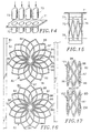
- Fig. 16 is a plan view of a pattern formed of a sheet of material which can be utilized for making another stent in tandem in accordance with the method of the present invention.
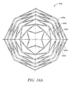
- Fig. 16A illustrates a flat stent pattern having a geometry similar to that shown in Fig. 16, except that it includes five successive diamond-shaped elements in tandem and the elements at one end of the resulting cylindrical structure will have an inherently smaller diameter than those at the other end of the cylindrical structure.
- Fig. 17 is a side-elevational view showing tandem stents made from the planar pattern shown in Fig. 16.
- Fig. 18 illustrates a planar eversible structure constructed in accordance with the principles of the present invention, having a continuous annular zig-zag pattern.
- Fig. 19 illustrates the structure of Fig. 18 after it has been everted according to the method of the present invention.
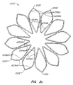
- Fig. 20 illustrates a planar eversible structure constructed in accordance with the principles of the present invention, having a continuous annular serpentine pattern.
- Fig. 21 illustrates the structure of Fig. 20 after it has been everted according to the method of the present invention.
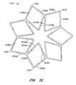
- Fig. 22 illustrates a planar eversible structure constructed in accordance with the principles of the present invention, having a discontinuous annular spiral filament.
- Fig. 23 illustrates the structure of Fig. 22 after it has been everted according to the method of the present invention.
- Fig. 24 illustrates a planar eversible structure constructed in accordance with the principles of the present invention, having a discontinuous serpentine spiral element arranged in an annular pattern.
- Fig. 25 illustrates the article of Fig. 24 after it has been everted according to the method of the present invention.
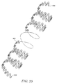
- Fig. 26 illustrates a particular spiral eversible article comprising a rectilinear pattern of serpentine elements.
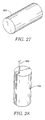
- Fig. 27 illustrates cylindrical rod stock that may be used as a starting material for the fabrication methods of the present invention.
- Fig. 28 illustrates a first alternative shaping operation that may be performed on the rod stock of Fig. 27.
- Fig. 29 illustrates the slicing of the rod stock of Fig. 27 after it has been shaped.
- Fig. 30 illustrates an alternative shaping method wherein the rod stock of Fig. 27 is sliced prior to patterning into the eversible articles of the present invention.
- Fig. 31 illustrates another embodiment of the planar eversible article of the present invention, wherein spacing between adjacent lattice elements is increased to facilitate fabrication by photochemical etching.
- Fig. 32 illustrates yet another embodiment of the planar eversible article of the present invention also having increased spacing between adjacent lattice elements.
- a method for making expansible stents having a generally cylindrical configuration with a pattern therein having interconnecting portions in accordance with the present invention from a sheet of material having a central portion comprises forming around said central portion in the sheet of material a pattern having a generally circular outer margin and corresponding to said pattern having interconnecting portions, separating the pattern from the sheet of material and causing relative movement between the central portion of the pattern and the outer margin of the pattern in a direction perpendicular to the plan of the central portion to transform the pattern into a cylinder to provide the expansible stent having the pattern therein.
- An appropriate heat treatment for the stent may thereafter be provided when desired.
- an exemplary method of the present invention is for making a stent 21 having a generally cylindrical configuration and having a pattern 22 therein to impart radial flexibility to the stent.
- a single row of lozenge or diamond-shaped openings 23 are provided in which the diamond-shaped openings are defined by elongate elements 24 with four of the same being provided for the four sides of the diamond-shaped opening 23 with the elements 24 abutting end to end and being continuous.
- the diamond-shaped openings 23 are lozenge-shaped and generally define a plane figure with four sides with two opposite obtuse angles and two opposite acute angles. As shown, two of the legs can have a length which is less than the length of the outer two legs.
- the elongate elements 24 forming each of the diamonds are connected to immediately adjacent diamonds on opposite sides by interconnecting portions (tabs) 26 formed of the same material as the elongate elements 24. As shown, the interconnecting portions 26 are near the apices of the obtuse angles formed by the elongate elements 24. It should be appreciated that more than four sides can be provided for defining the openings 23 if desired and still encompass the features of the present invention. Because of the diamond-shaped configuration, it can be seen that the cylindrical stent 21 can be compressed radially and at the same time provide outwardly facing radial forces to maintain the patency of the lumen of the vessel of a human body in a manner will known to those skilled in the art.
- the diamond-shaped elements of Fig. 3 will frequently be preferred, it is possible to substitute a variety of other closed peripheral structures for the diamonds.
- the closed peripheral structures can be circular, oval, polygonal, irregular, or the like.
- the only requirement is that the structure be capable of expanding in width to accommodate expansion of the resulting cylindrical stent structure after eversion.
- an exemplary planar reversible article 200 which can be everted into a cylindrical wall portion may comprise a plurality of oval-shaped elements, as illustrated in Fig. 3A.
- the ovals 202 are arranged so that they have elongate axes 204 aligned radially and are connected by tabs 206 which lie along a common diametric line 206.
- Such a structure is particularly convenient since the oval elements 202 (or the diamond-shaped elements of Fig. 3) may be everted about the diametric line 208, with the inner peripheral ends 210 moving away from each other in a radially expanding direction and/or the outer peripheral ends 212 moving closer to each other in a radially collapsing pattern. Specific everting techniques are described in more detail below.
- FIG. 3B Another planar eversible article 300 is illustrated in Fig. 3B.
- the article 300 comprises eleven lozenge (diamond)-shaped elements 302a-302k.
- the principle distinction of the article 300 is that the various diamond-shaped elements 302a-302k have different radial lengths.
- the radial length in the planar configuration of Fig. 3B will become the axial length after the article 300 is everted.
- the cylindrical stent structure which results from everting planar article 300 will have a shorter length on one side and a longer length on the other side, i.e. the ends will appear angled or chamfered.
- Such chamfered structures will be useful in treating asymmetric lesions and/or for joining successive stent structures in order to make a curved multisegmented stent.
- the ends of the cylindrical wall which results from everting structure 300 of Fig. 3B may be joined together, e.g. by tying, welding, or the like.
- a sheet 31 of a suitable material is provided.
- the sheet 31 can be formed of an elongate strip in which the strip has a width which is slightly greater than the width of the patterns 32 formed therein with the patterns 32 being spaced longitudinally of the strip as shown in Fig. 2.
- the sheet 31 can have a suitable starting thickness as for example from 0.005" to 0.040" which may thin down during the steps hereinafter described to a final thickness of 0.003" to 0.030".
- the material utilized for the sheet 31 should be of a material which is useful in stents, as for example it should be of a biocompatible material.
- Nitinol alloys have an 8% elasticity versus approximately a half percent elasticity for stainless steel. Additional characteristics of nickel titanium alloys which are useful in the present invention are thereinafter described.
- the patterns 32 correspond generally to the pattern 22 shown in Fig. 1. As shown in Figs. 2 and 3, the patterns 32 are provided with a plurality of diamond-shaped openings 33 which are diamond or lozenge-shaped as hereinbefore described.
- the openings 33 are defined by elongate elements 34 which are formed from the sheet 31 and therefore have a substantially rectangular cross section with four of the elongate elements 34 forming a diamond-shaped opening 33 with two opposite obtuse angles and two opposite acute angles and with interconnecting portions 36 interconnecting the elongate elements at the portions of the elongate elements 34 forming the obtuse angles.
- a plurality of diamond-shaped openings 33 circumferentially disposed around a central opening 37 and in which the outermost acute angles lie in a circle to provide an outer generally circular margin 38 which is concentric with the central opening 37.
- the arrangement of the elongate elements 34 with interconnecting portions 36 form a geometric circular pattern 32 as shown.
- the individual patterns 32 remain supported within the sheet 31 by support tabs 39 which are formed from the sheet 31 and which are attached to the outer portions of the elongate elements 34 forming the outermost acute angle of the diamond-shaped openings 33.
- the patterns 32 can be formed in any suitable convention manner. For example, they can be formed by photochemical etching, laser cutting, stamping or wire EDM. It can be seen that the construction is such that the patterns can be readily stamped out sequentially by running the same through a punch press with the appropriate dies.
- each pattern 32 can be loaded onto a tapered mandrel 41 by inserting the tapered portion 41a of the mandrel 41 through the central opening 37 and causing the central opening to be expanded and to cause the pattern 32 to assume a cone shape as shown in Fig. 4.
- Continued movement of the pattern 32 over the tapered portion 41a onto the cylindrical portion 41b of the mandrel 41 causes it to move from the intermediate cone shape to assume a generally cylindrical shape as shown in Fig. 5.
- the cylindrical portion 41b is sized to be of the diameter desired for the stent to be formed from the pattern. It should be appreciated that if desired the transition in the pattern can be accomplished without the use of a mandrel.
- additional patterns 32 can be loaded onto the same mandrel and to retain them in a desired maximum diameter to be incorporated therein during the heat treatment.
- a sleeve 42 of a suitable material such as stainless can be placed over the mandrels and over the patterns 32 to hold the spaced-apart patterns in place on the mandrel.
- the assembly can then be placed in an oven for heat treatment of the patterns 32 to provide stents having the desired characteristics as well as a memory of the maximum diameter.
- nickel titanium alloys can be heat treated or annealed at a temperature ranging from 300°C to 800°C with the time of heat treatment ranging from a few seconds to an hour or more.
- the mandrel with the heat treated patterns thereon can be permitted to cool to room temperature after which the sleeve 42 can be removed.
- the patterns 32 can then be removed from the mandrel to provide the stents 21 of the type shown in Fig. 1.
- planar articles of the present invention can be everted in a number of other ways.
- they can be fed into the inner lumen of a tubular mandrel, with the radially outward periphery of the article being collapsed to fit into the lumen.
- they can be everted between coaxial, sliding tubes and/or axially sliding pins which engage radially inward and radially outward points on the articles to effect the eversion.
- the patterns can be formed from the planar shape into the cylindrical shape in a single step without the necessity of heat treating them.
- the stent be superelastic at room temperature or at body temperature, it is heat treated so that if deformed the stent will have a desire to come back to the shape it was in at the time it was heat treated. Thus, it will have a memory of this shape and size and if compressed from that size and shape, it will self expand to the heat treated shape after it has been released.
- the nickel titanium superelastic material typically is a binary material such at NI (50.8 WT%) and TI or a ternary alloy such as NiTi-V.
- a binary alloy such as a nickel titanium alloy and a ternary alloy nickel titanium and copper can be utilized. Iron-based shape memory alloys are also good candidates for this application.
- the stainless steel can be of a suitable material such as 304V.
- a suitable material such as 304V.
- alloys such as stainless steel or titanium alloys
- other titanium alloys known to those skilled in the art or composites of the aforementioned alloys.
- Superelasticity typically can be introduced into a cold-working nickel titanium alloy used for the stent at 350°C to 500°C for a period of a few seconds to an hour or more.
- a solution treatment of 700°C to 800°C for a period of 10 to 40 minutes followed by rapid quenching in a cold fluid such as water and aging at 300°C to 500°C for 5 to 60 minutes can be utilized.
- two stent forms can be provided with the nickel titanium alloy in its martensitic state at room temperature.
- the stent is deformed into a small shape and then delivered to the desired location after which the stent can be heated to cause it to expand to its memorized or final state.
- the stent is placed in a desired location with mechanical means such as a balloon in a manner well known to those skilled in the art to cause it to expand and to leave the stent in place in its martensitic state.
- mechanical means such as a balloon in a manner well known to those skilled in the art to cause it to expand and to leave the stent in place in its martensitic state.
- FIG. 7 A side-elevational view of the stent 21 is shown in Fig. 7 in which the outside diameter and the length of the stent is given. With the patterns hereinbefore described, typically the length L of the stent is less than the outside diameter OD of the stent.
- a stent 46 having a double-diamond pattern rather than a single diamond pattern.
- This double-diamond pattern makes it possible to optimize the stiffness of the stent while at the same time providing a stent of greater length without having longer diamond-shaped openings.
- the pattern 46 can be formed in the manner hereinbefore described from sheet material of the type hereinbefore described.
- the first row of diamond-shaped openings 47 are formed by elongate elements 51 of the sheet material forming spaced-apart oppositely-facing obtuse angles which are circumferentially arranged and opposed oppositely facing acute angles which are radially disposed. Interconnecting portions 52 are provided between the elongate elements 51 at the portions forming the obtuse angles.
- the second or outer row of diamond-shaped openings 48 are formed by elongate elements 53 which are also arranged to form oppositely facing obtuse angles disposed circumferentially and oppositely facing acute angles extending radially. Interconnecting portions 54 located at the positions of the obtuse angles in the outer row serve to interconnect the elongate elements 53.
- the pattern 46 is supported by tabs 56 in the sheet 57.
- the pattern 46 can be formed in the manner hereinbefore described. It can be separated from the sheet 57 by severing the tabs 56.
- the pattern can then be inserted over the mandrel 41 as shown in Fig. 9 to cause a transformation of the pattern from a planar configuration to the cylindrical configuration shown in Fig. 9.
- This serves to provide the stent 44 having a greater length and which has a double-diamond configuration to provide an optimized stiffness for the stent.
- the desired rigidity or stiffness can be obtained by varying the design of the diamond-shaped openings. The wider the diamond-shaped openings, the greater the flexibility and the greater the softness. When the diamonds are narrower or smaller, the stent becomes more rigid and less soft.
- Fig. 10 Another method is shown in Fig. 10 which is used when it is desired to provide a stent 58 which has a length which is greater than the outside diameter of the stent.
- a stent 21 of the type shown in Fig. 6 is mechanically compressed as shown in Fig. 10 to decrease its outside diameter, for example by 50 percent. This causes elongation of the diamond-shaped openings 23 and increases the length of the stent as represented by a length L which is greater than the outside diameter OD.
- a stent made in accordance with the present invention having an outside diameter which is at least as great as the desired length after which the stent after it has been positioned can be compressed down into a smaller diameter until the desired length of stent has been obtained.
- Such a stent with heat treatment will have a memory causing it to want to return to its original shape and thereby applying the desired yieldable radial forces on the vessel in which the stent is used.
- FIG. 11 Still another method for making stents in accordance with the present invention is shown in Figs 11, 12, and 13.
- a pattern 61 is provided in a sheet 62.
- the pattern 61 is very similar to the patterns hereinbefore described with the exception that the central portion 63 is solid rather than being an opening so that the central portion 63 is integral with the elongate elements 64 forming the diamond-shaped openings 66.
- the elongate elements 64 are provided with interconnecting portions 67.
- Support tabs 68 are provided to support the elongate elements 64 in the sheet 62.
- a plurality of such patterns 61 can be formed in a sheet 62 in the form of a sheet metal strip in which the patterns are spaced apart longitudinally of the strip.
- Each of the patterns can then be punched out simultaneously or sequentially by the use of a punch represented schematically at 69 in Fig. 13 to cause deep drawing of the pattern into a die (not shown) to cause the transformation from the planar configuration to a cylindrical configuration in the form of a cup 72 as shown in Fig. 14.
- the punch 69 is removed and the lower portion of the pattern 61 can be removed along the cut line 70.
- the pattern 61 can be removed along the cut line 70.
- the pattern 61 in cylindrical form can be separated from the sheet 62 by severing the same at or adjacent to the plane of the sheet. Thereafter what remains is a stent (not shown) having a cylindrical configuration and having the pattern hereinbefore described therein as in the previous embodiments.
- sheet material 71 as shown in Fig. 14 can be utilized and cylindrical cups 72 can be deep drawn from the sheet 71 by punches 73 either simultaneously or sequentially. Thereafter, a diamond-shaped pattern 76 of the type hereinbefore described can be formed into the cylindrical cups 72 by a suitable technique of the type hereinafter described. These patterns can be formed while the cups 72 are attached to the sheet 71, or alternatively the patterns can be formed after the cups 72 have been removed along the cut line 77 and the central portion of the pattern 76 removed along the cut line 78 to provide a cylindrical stent (not shown) of the type hereinbefore described.
- Figs. 12, 13, 14, and 15 The method shown in Figs. 12, 13, 14, and 15 is particularly desirable for use with sheet material formed of nickel titanium alloys.
- nickel titanium alloys have been difficult to form into hypotubes.
- Figs. 16 and 17 show a method for making a tandem stent in accordance with the present method.
- a sheet 81 in the form of a strip in which a repetitive pattern 82 is provided.
- Each of the patterns 82 has a generally circular inner portion 83 and a generally circular outer margin 84.
- the pattern 82 is formed with three rows 86, 87, and 88 of diamond-shaped openings delineated by elongate elements 92 of the sheet material of the type hereinbefore described.
- the diamond-shaped openings hereinbefore described have been described as having four sides and the openings 86, 87 and 88 can also be considered to be four-sided diamond-shaped openings. However, as can be seen from Fig. 16, these openings can be considered as having six sides with two additional sides being provided by the truncated distal extremities of the diamond-shaped openings.
- Interconnecting portions 96 on opposite sides of the pattern 82 support the pattern in the sheet.
- additional interconnecting portions 97 which serve to interconnect two of the patterns 82 into a tandem pattern arrangement. Support tabs 98 support the tandem pattern in the sheet 81.
- an eversible article 400 having a pattern including five rows 402a-402e of lozenge (diamond)-shaped elements is illustrated.
- Each of the lozenges comprises four beams or struts, and it can be seen that the lengths of the struts of each diamond increase as the row moves radially outward. That is, the struts of diamond 402a are the smallest, the struts of diamond 402b are the next largest, while the struts of diamonds 402c are the next largest, etc., until the struts of diamond 402e are the largest of all.
- the planar article 400 will thus form a cylindrical wall having a different structure at one end than at the other end.
- the cylindrical wall will have a smaller diameter at the end having diamonds 402a and a larger diameter at the end having diamonds 402e.
- a tapered cylindrical structure will be advantageous whenever it is desired to have a tapered stent or to have a transition region within a larger stent assembly or vascular prosthesis structure.
- the cylinder resulting from everting the planar article 400 could have a uniform diameter, in which case the diamonds 402a would have to be opened more widely and the diamonds 402e would have to be opened less widely (i.e. be longitudinally extended) in order to maintain an equal diameter.
- the tandem stent shown in Fig. 17 can be readily formed from the tandem pattern shown in Fig. 16. This can be accomplished by punching out two of the joined-together patterns by severing the tabs 98. Thereafter, a tapered cylindrical mandrel is provided rather than a cylinder which has been provided with a conical tip. The mandrel is used to transfer the pattern from sheet form into cylindrical form in the manner hereinbefore described by forming the patterns 82 into a cylindrical form in sequence to provide two stents 101 and 102 which are axially aligned and which remain interconnected by the interconnecting portion 97. Thus, in a medical procedure the tandem stents can be used to maintain patency of a vessel over a longer length.
- the method of the present invention makes it possible to readily transform planar sheet material into cylindrical material to provide expansible stents.
- the method of the present invention lends itself to mass production of stents so that they can be made rapidly and inexpensively, even from difficult materials such as nickel titanium alloys.
- a planar eversible article 500 (Fig. 18) is fabricated to have a plurality of generally straight struts 502 in an open star-shaped configuration.
- the struts 502 are joined as a plurality of circumferentially spaced-apart V-shaped components, with each V-shaped component joined at its radially outward end to the adjacent V-shaped component. The pattern shown in Fig.
- each of the struts 502 may be initially be provided as a discrete element, and the individual struts then attached, for example by welding, into the illustrated pattern.
- the eversible planar article 500 may then be everted into a cylindrical zig-zag stent cylindrical stent segment, as illustrated in Fig. 19.
- a planar eversible article 600 comprising eight U-shaped elements joined in an annular serpentine pattern as illustrated in Fig. 20.
- Each of the U-shaped segment 602 has a peripherally inward end 604 and a peripherally outward end 606.
- a cylindrical wall segment comprising a serpentine element is formed, as shown in Fig. 21.
- the cylindrical element shown in Fig. 21 may be used by itself, or may be joined to form a multiply segmented stent or graft structure in a conventional manner.
- FIG. 22 Still another eversible planar structure 700 is illustrated in Fig. 22.
- the structure 700 comprises a single filament 72, shown in the form of a ribbon, which is spirally wound so that first end 704 lies at a radially outward point and a second end 706 lies at the radially inward point.
- the spiral which includes only the single element 702, thus defines the annular lattice which may be everted to form a cylindrical wall segment as shown in Fig. 23.
- FIG. 24 A variation of the spiral pattern of Fig. 22 is shown in Fig. 24.
- Eversible planar article 800 comprises a single spiral element 802 having an outer end 804 and an inner end 806.
- the spiral element 802 is not a single continuously curved element, as shown in Fig. 22, but rather possesses a secondary serpentine pattern superimposed on the spiral.
- Planar article 800 may be everted to assume the complex helically wound serpentine pattern shown in Fig. 25.
- the eversible planar structure 900 of Fig. 26 shows another serpentine element 902 which has been patterned from a flat sheet of material, typically a metal sheet formed by photochemical etching. Instead of being shown in a uniformly curved spiral, however, the eversible planar article 900 is shown in a rectilinear "spiral" pattern, having an outer end 904 and an inner end 906. After removing the serpentine element 902 from its frame, the serpentine element may be everted to form a cylindrical wall portion similar to that shown in Fig. 25.
- the article 900 further includes a plurality of eyelets 910 which permit attachment of sutures, clips, or other fasteners for securing successive turns of the helix together.
- the rod 950 may be composed of any of the materials described above and will generally have a circular cross-section.
- the diameter of the rod will be selected to correspond generally to the diameter of the planar articles which are to be produced.
- Use of the rod 950 as starting material is thus particularly preferred for forming non-linked cylindrical wall segments. Thus, it will be less useful for forming linked or hinged segments as shown in Figs. 16 and 17.
- the rod stock 950 will have a length suitable for producing a number of discrete eversible planar articles.
- the rod stock 950 will eventually be sliced into individual pieces having a desired thickness.
- Each of the pieces either will have been or will be patterned to have the desired stent geometry, typically by a cutting process, such as EDM.
- the rod stock may first be patterned using an EDM wire 952 in a conventional manner.
- the exterior of the rod stock 950 may first be patterned, e.g. to obtain a star configuration.
- the rod stock can be extruded, cast, or micromachined, or otherwise initially formed to have the desired external geometry.
- the EDM wire 952 will later be used to form the internal patterns required for the stent geometry. Formation of the internal patterns will usually require that a hole first be drilled or otherwise formed in an axial direction through the rod stock 950 in order to permit access for the EDM wire 952. As shown in Fig. 29, the rod stock 950 may be completely patterned prior to using the EDM wire 952 to slice individual eversible planar articles 954 therefrom. Alternatively, the rod stock 950 may be sliced to produce solid circular blanks 956, as shown in Fig. 30. The blanks 956 may then be stacked and patterned, usually by EDM cutting, to simultaneously form the plurality of individual reversible planar articles.
- the present invention contemplates that either the slicing or the patterning steps may be performed first, and in some cases may be performed alternately in order to produce the articles of the present invention.
- the tube stock will have a wall thickness sufficient to accommodate the diameter of the desired planar article.
- the tube can then be sliced to provide the articles, either before or after patterning. Multiple articles can be obtained from each slice.
- the advantages of grain uniformity will generally be the same as with rod stock, and fabrication may be somewhat simplified.
- planar article 1000 in Fig. 31 includes eleven tear-drop shaped closed peripheral structures 1002, each of which includes a pair of straight radially inward legs 1004a and 1004b.
- Legs 1004a and 1004b on adjacent structures 1002 diverge to provide sufficient spacing to increase the accuracy and precision of the etch. Radially outward legs 1006a and 1006b are curved. Planar article 1100 in Fig 32 is similar, with radially inward legs 1004a and 1104b of adjacent structures 1102 diverging. Radially outward legs 1106a and 1106b, however, are not curved.
Landscapes
- Health & Medical Sciences (AREA)
- Engineering & Computer Science (AREA)
- Biomedical Technology (AREA)
- Heart & Thoracic Surgery (AREA)
- Life Sciences & Earth Sciences (AREA)
- Cardiology (AREA)
- Oral & Maxillofacial Surgery (AREA)
- Transplantation (AREA)
- Veterinary Medicine (AREA)
- Vascular Medicine (AREA)
- Public Health (AREA)
- Animal Behavior & Ethology (AREA)
- General Health & Medical Sciences (AREA)
- Optics & Photonics (AREA)
- Physics & Mathematics (AREA)
- Mechanical Engineering (AREA)
- Media Introduction/Drainage Providing Device (AREA)
- Prostheses (AREA)
Abstract
Claims (39)
- Procédé de fabrication d'un implant cylindrique (21, 46, 58) à partir d'une feuille plane (31, 57, 62, 71, 81) présentant une structure en réseau, caractérisé en ce qu'un réseau annulaire plan (32, 200) est formé à partir de la feuille plane (31) et en ce que les bords périphériques interne et externe du réseau annulaire (32, 200) sont soumis à une rotation de l'un par rapport à l'autre autour d'une ligne annulaire entre le bord périphérique interne et le bord périphérique externe afin de former une paroi cylindrique, une extrémité de la paroi cylindrique étant formée par le bord périphérique interne et l'autre extrémité étant formée par le bord périphérique externe.
- Procédé selon la revendication 1, dans lequel le réseau annulaire comprend des éléments interconnectés qui sont reliés suivant au moins un trajet continu.
- Procédé selon la revendication 1 ou 2, dans lequel le réseau annulaire comprend une bague en serpentin annulaire.
- Procédé selon l'une quelconque des revendications 1 à 3, dans lequel le réseau annulaire comprend une pluralité de structures périphériques fermées.
- Procédé selon la revendication 4, dans lequel les structures périphériques fermées sont polygonales, en particulier, en forme de losange.
- Procédé selon la revendication 1 ou 2, dans lequel le réseau annulaire comprend une spirale avec une extrémité radialement interne et une extrémité radialement externe.
- Procédé selon la revendication 6, dans lequel la spirale est superposée à un profil en serpentin.
- Procédé selon la revendication 6, dans lequel la spirale présente une géométrie rectiligne.
- Procédé selon l'une quelconque des revendications 1 à 7, dans lequel la feuille plane est mise en forme suivant un certain profil.
- Procédé selon la revendication 9, dans lequel la formation de profil comprend l'attaque photochimique.
- Procédé selon la revendication 9 ou 10, dans lequel la formation de profil comprend la découpe du réseau annulaire à partir de la feuille plane.
- Procédé selon la revendication 11, dans lequel la découpe comprend l'usinage par électroérosion.
- Procédé selon la revendication 11, dans lequel la découpe comprend la découpe au laser.
- Procédé selon la revendication 13, dans lequel une pluralité de feuilles planes est agencée en un empilement et l'empilement est découpé.
- Procédé selon la revendication 9, dans lequel la formation de profil comprend l'emboutissage de la feuille plane.
- Procédé selon l'une quelconque des revendications 1 à 8, dans lequel la feuille plane présentant une structure en réseau est réalisée par pliage d'un filament continu et liaison des éléments discrets multiples entre eux.
- Procédé selon l'une quelconque des revendications 1 à 16, dans lequel le réseau annulaire est composé d'un métal.
- Procédé selon la revendication 17, dans lequel le métal est un alliage à mémoire de forme, en particulier un alliage au nickel titane.
- Procédé selon la revendication 17, dans lequel le métal est sélectionné à partir du groupe constitué par l'acier inoxydable, le titane, le tantale, le platine et l'elgiloy.
- Procédé selon l'une quelconque des revendications 1 à 19, dans lequel la paroi cylindrique remise en forme est traitée afin de modifier au moins une propriété physique.
- Procédé selon la revendication 20, dans lequel le traitement comprend un traitement thermique.
- Procédé selon l'une quelconque des revendications 1 à 21, dans lequel le réseau annulaire (32, 200) est formé en une paroi cylindrique pouvant être expansée radialement.
- Procédé selon l'une quelconque des revendications 4 à 22, dans lequel le réseau annulaire (32, 200) comprend une pluralité d'éléments en forme de losange (24, 202, 302a à 302k, 51, 53, 64, 92) présentant des axes qui sont alignés radialement à l'intérieur du réseau annulaire (32, 200) dans lequel des éléments adjacents en forme de losange (24, 202, 302a à 302k, 51, 53, 64, 92) sont reliés l'un à l'autre.
- Procédé selon la revendication 23, dans lequel les éléments adjacents en forme de losange (24, 202, 302a à 302k, 51, 53, 64, 92) sont reliés l'un à l'autre par des pattes (26, 206, 67, 96) situées le long d'une ligne diamétrale commune (208) à l'intérieur du réseau annulaire.
- Procédé selon la revendication 24, dans lequel le réseau annulaire comprend au moins deux rangées annulaires radialement successives d'éléments en forme de losange (51, 53, 92).
- Structure plane destinée à fabriquer un implant cylindrique (21, 46, 58) comprenant une structure en réseau plane, caractérisée en ce que la structure en réseau est annulaire et comprend des éléments interconnectés (24, 202, 302a à 302k, 51, 53, 64, 92), le bord périphérique interne et le bord périphérique externe du réseau annulaire (32, 200) pouvant tourner l'un par rapport à l'autre autour d'une ligne annulaire entre les bords périphériques interne et externe afin de former une paroi cylindrique pouvant être expansée radialement, le bord périphérique interne et le bord périphérique externe devenant chacun l'une des extrémités de la paroi cylindrique.
- Structure selon la revendication 26, dans laquelle les éléments interconnectés sont reliés suivant au moins un trajet annulaire continu.
- Structure selon la revendication 26 ou 27, dans laquelle la structure en réseau comprend une bague en serpentin annulaire pouvant être déformée en une bague en serpentin cylindrique.
- Structure selon l'une quelconque des revendications 26 à 28, dans laquelle la structure en réseau comprend une pluralité d'éléments en forme de losange (24, 202, 302a à 302k, 51, 53, 64, 92) présentant des axes qui sont alignés radialement à l'intérieur du réseau annulaire.
- Structure selon la revendication 29, dans laquelle les éléments adjacents en forme de losange (24, 202, 302a à 302k, 51, 53, 64, 92) sont reliés l'un à l'autre par des pattes (26, 206, 67, 96) situées le long d'une ligne diamétrale commune (208) à l'intérieur du réseau annulaire.
- Structure selon la revendication 29 ou 30, dans laquelle sont formées au moins deux rangées annulaires d'éléments en forme de losange (51, 53, 92) espacées radialement.
- Structure selon l'une quelconque des revendications 26 à 28, dans laquelle la structure en réseau comprend une spirale qui peut être déformée en une bobine hélicoïdale pouvant être expansée radialement.
- Structure selon la revendication 32, dans laquelle la structure en réseau comprend un élément en serpentin enroulé en spirale pouvant être déformé en un élément en serpentin enroulé de manière hélicoïdale.
- Structure selon l'une quelconque des revendications 26 à 33, dans laquelle la structure en réseau est pliée à partir d'un filament continu.
- Structure selon l'une quelconque des revendications 26 à 33, dans laquelle la structure en réseau comprend une pluralité d'éléments discrets reliés entre eux.
- Structure selon l'une quelconque des revendications 26 à 35, dans laquelle la structure en réseau est composée d'un métal.
- Structure selon la revendication 36, dans laquelle le métal est un alliage à mémoire de forme.
- Structure selon la revendication 37, dans laquelle le métal est un alliage nickel titane.
- Structure selon la revendication 37, dans laquelle le métal est sélectionné à partir du groupe constitué par l'acier inoxydable, le titane, le tantale, le platine et l'elgiloy.
Applications Claiming Priority (3)
| Application Number | Priority Date | Filing Date | Title |
|---|---|---|---|
| US59351596A | 1996-01-30 | 1996-01-30 | |
| US593515 | 1996-01-30 | ||
| PCT/US1997/001488 WO1997027959A1 (fr) | 1996-01-30 | 1997-01-29 | Articles pour la fabrication d'extenseurs et procedes associes |
Publications (3)
| Publication Number | Publication Date |
|---|---|
| EP1011889A1 EP1011889A1 (fr) | 2000-06-28 |
| EP1011889A4 EP1011889A4 (fr) | 2000-06-28 |
| EP1011889B1 true EP1011889B1 (fr) | 2002-10-30 |
Family
ID=24375022
Family Applications (1)
| Application Number | Title | Priority Date | Filing Date |
|---|---|---|---|
| EP97906450A Expired - Lifetime EP1011889B1 (fr) | 1996-01-30 | 1997-01-29 | Articles pour la fabrication d'extenseurs et procedes associes |
Country Status (5)
| Country | Link |
|---|---|
| US (2) | US5907893A (fr) |
| EP (1) | EP1011889B1 (fr) |
| JP (1) | JP2001502605A (fr) |
| DE (1) | DE69716779T2 (fr) |
| WO (1) | WO1997027959A1 (fr) |
Cited By (1)
| Publication number | Priority date | Publication date | Assignee | Title |
|---|---|---|---|---|
| DE102015122113A1 (de) * | 2015-12-17 | 2017-06-22 | Acandis Gmbh & Co. Kg | Verfahren zur Herstellung eines medizinischen Implantats, flache Gitterstruktur zur Bildung eines medizinischen Implantats und Implantat zur Behandlung von Blutgefäßerkrankungen |
Families Citing this family (509)
| Publication number | Priority date | Publication date | Assignee | Title |
|---|---|---|---|---|
| JP4636634B2 (ja) * | 1996-04-26 | 2011-02-23 | ボストン サイエンティフィック サイムド,インコーポレイテッド | 脈管内ステント |
| US6006134A (en) | 1998-04-30 | 1999-12-21 | Medtronic, Inc. | Method and device for electronically controlling the beating of a heart using venous electrical stimulation of nerve fibers |
| US5928279A (en) * | 1996-07-03 | 1999-07-27 | Baxter International Inc. | Stented, radially expandable, tubular PTFE grafts |
| US6599316B2 (en) | 1996-11-04 | 2003-07-29 | Advanced Stent Technologies, Inc. | Extendible stent apparatus |
| US7591846B2 (en) | 1996-11-04 | 2009-09-22 | Boston Scientific Scimed, Inc. | Methods for deploying stents in bifurcations |
| US6835203B1 (en) | 1996-11-04 | 2004-12-28 | Advanced Stent Technologies, Inc. | Extendible stent apparatus |
| US8211167B2 (en) | 1999-12-06 | 2012-07-03 | Boston Scientific Scimed, Inc. | Method of using a catheter with attached flexible side sheath |
| US6692483B2 (en) | 1996-11-04 | 2004-02-17 | Advanced Stent Technologies, Inc. | Catheter with attached flexible side sheath |
| US6325826B1 (en) | 1998-01-14 | 2001-12-04 | Advanced Stent Technologies, Inc. | Extendible stent apparatus |
| WO1998020810A1 (fr) | 1996-11-12 | 1998-05-22 | Medtronic, Inc. | Protheses intracavitaires souples radialement expansibles |
| US5906759A (en) * | 1996-12-26 | 1999-05-25 | Medinol Ltd. | Stent forming apparatus with stent deforming blades |
| US7959664B2 (en) * | 1996-12-26 | 2011-06-14 | Medinol, Ltd. | Flat process of drug coating for stents |
| US5902475A (en) * | 1997-04-08 | 1999-05-11 | Interventional Technologies, Inc. | Method for manufacturing a stent |
| US6726829B2 (en) | 1997-04-08 | 2004-04-27 | Scimed Life Systems, Inc. | Method of manufacturing a stent |
| US8172897B2 (en) | 1997-04-15 | 2012-05-08 | Advanced Cardiovascular Systems, Inc. | Polymer and metal composite implantable medical devices |
| US6240616B1 (en) | 1997-04-15 | 2001-06-05 | Advanced Cardiovascular Systems, Inc. | Method of manufacturing a medicated porous metal prosthesis |
| US10028851B2 (en) | 1997-04-15 | 2018-07-24 | Advanced Cardiovascular Systems, Inc. | Coatings for controlling erosion of a substrate of an implantable medical device |
| US5954766A (en) | 1997-09-16 | 1999-09-21 | Zadno-Azizi; Gholam-Reza | Body fluid flow control device |
| US6395019B2 (en) | 1998-02-09 | 2002-05-28 | Trivascular, Inc. | Endovascular graft |
| US6497724B1 (en) * | 1999-04-30 | 2002-12-24 | The Board Of Trustees Of The Leland Stanford Junior University | Expandable space frame |
| AU754156B2 (en) * | 1998-06-02 | 2002-11-07 | Cook Incorporated | Multiple-sided intraluminal medical device |
| US7452371B2 (en) * | 1999-06-02 | 2008-11-18 | Cook Incorporated | Implantable vascular device |
| US6203732B1 (en) * | 1998-07-02 | 2001-03-20 | Intra Therapeutics, Inc. | Method for manufacturing intraluminal device |
| US7128073B1 (en) * | 1998-11-06 | 2006-10-31 | Ev3 Endovascular, Inc. | Method and device for left atrial appendage occlusion |
| US7655030B2 (en) | 2003-07-18 | 2010-02-02 | Boston Scientific Scimed, Inc. | Catheter balloon systems and methods |
| US6355057B1 (en) | 1999-01-14 | 2002-03-12 | Medtronic, Inc. | Staggered endoluminal stent |
| US6464723B1 (en) * | 1999-04-22 | 2002-10-15 | Advanced Cardiovascular Systems, Inc. | Radiopaque stents |
| CA2368252A1 (fr) | 1999-04-25 | 2000-11-02 | Brainwave Cardio-Vascular Technologies Ltd. | Stent double feuille |
| US20060238702A1 (en) | 1999-04-30 | 2006-10-26 | Advanced Medical Optics, Inc. | Ophthalmic lens combinations |
| US6375676B1 (en) * | 1999-05-17 | 2002-04-23 | Advanced Cardiovascular Systems, Inc. | Self-expanding stent with enhanced delivery precision and stent delivery system |
| US6733513B2 (en) | 1999-11-04 | 2004-05-11 | Advanced Bioprosthetic Surfaces, Ltd. | Balloon catheter having metal balloon and method of making same |
| US6610087B1 (en) | 1999-11-16 | 2003-08-26 | Scimed Life Systems, Inc. | Endoluminal stent having a matched stiffness region and/or a stiffness gradient and methods for providing stent kink resistance |
| US8016877B2 (en) | 1999-11-17 | 2011-09-13 | Medtronic Corevalve Llc | Prosthetic valve for transluminal delivery |
| US7018406B2 (en) | 1999-11-17 | 2006-03-28 | Corevalve Sa | Prosthetic valve for transluminal delivery |
| US8579966B2 (en) | 1999-11-17 | 2013-11-12 | Medtronic Corevalve Llc | Prosthetic valve for transluminal delivery |
| US7195641B2 (en) | 1999-11-19 | 2007-03-27 | Advanced Bio Prosthetic Surfaces, Ltd. | Valvular prostheses having metal or pseudometallic construction and methods of manufacture |
| US6537310B1 (en) * | 1999-11-19 | 2003-03-25 | Advanced Bio Prosthetic Surfaces, Ltd. | Endoluminal implantable devices and method of making same |
| US6379383B1 (en) * | 1999-11-19 | 2002-04-30 | Advanced Bio Prosthetic Surfaces, Ltd. | Endoluminal device exhibiting improved endothelialization and method of manufacture thereof |
| US7235092B2 (en) * | 1999-11-19 | 2007-06-26 | Advanced Bio Prosthetic Surfaces, Ltd. | Guidewires and thin film catheter-sheaths and method of making same |
| US10172730B2 (en) * | 1999-11-19 | 2019-01-08 | Vactronix Scientific, Llc | Stents with metallic covers and methods of making same |
| US7300457B2 (en) | 1999-11-19 | 2007-11-27 | Advanced Bio Prosthetic Surfaces, Ltd. | Self-supporting metallic implantable grafts, compliant implantable medical devices and methods of making same |
| US6849085B2 (en) | 1999-11-19 | 2005-02-01 | Advanced Bio Prosthetic Surfaces, Ltd. | Self-supporting laminated films, structural materials and medical devices manufactured therefrom and method of making same |
| US6936066B2 (en) * | 1999-11-19 | 2005-08-30 | Advanced Bio Prosthetic Surfaces, Ltd. | Complaint implantable medical devices and methods of making same |
| US7736687B2 (en) | 2006-01-31 | 2010-06-15 | Advance Bio Prosthetic Surfaces, Ltd. | Methods of making medical devices |
| US8458879B2 (en) | 2001-07-03 | 2013-06-11 | Advanced Bio Prosthetic Surfaces, Ltd., A Wholly Owned Subsidiary Of Palmaz Scientific, Inc. | Method of fabricating an implantable medical device |
| AU3441001A (en) * | 1999-12-01 | 2001-06-12 | Advanced Cardiovascular Systems Inc. | Nitinol alloy design and composition for vascular stents |
| US7842068B2 (en) | 2000-12-07 | 2010-11-30 | Integrated Vascular Systems, Inc. | Apparatus and methods for providing tactile feedback while delivering a closure device |
| US9579091B2 (en) | 2000-01-05 | 2017-02-28 | Integrated Vascular Systems, Inc. | Closure system and methods of use |
| US8758400B2 (en) | 2000-01-05 | 2014-06-24 | Integrated Vascular Systems, Inc. | Closure system and methods of use |
| US6461364B1 (en) | 2000-01-05 | 2002-10-08 | Integrated Vascular Systems, Inc. | Vascular sheath with bioabsorbable puncture site closure apparatus and methods of use |
| US6391048B1 (en) | 2000-01-05 | 2002-05-21 | Integrated Vascular Systems, Inc. | Integrated vascular device with puncture site closure component and sealant and methods of use |
| US6942674B2 (en) | 2000-01-05 | 2005-09-13 | Integrated Vascular Systems, Inc. | Apparatus and methods for delivering a closure device |
| US8241274B2 (en) | 2000-01-19 | 2012-08-14 | Medtronic, Inc. | Method for guiding a medical device |
| JP4404240B2 (ja) * | 2000-02-03 | 2010-01-27 | クック インコーポレイティド | 弁及び移植可能な脈管弁 |
| US20050267560A1 (en) * | 2000-02-03 | 2005-12-01 | Cook Incorporated | Implantable bioabsorbable valve support frame |
| US6679264B1 (en) | 2000-03-04 | 2004-01-20 | Emphasys Medical, Inc. | Methods and devices for use in performing pulmonary procedures |
| US20030070683A1 (en) | 2000-03-04 | 2003-04-17 | Deem Mark E. | Methods and devices for use in performing pulmonary procedures |
| US8474460B2 (en) | 2000-03-04 | 2013-07-02 | Pulmonx Corporation | Implanted bronchial isolation devices and methods |
| JP2003526448A (ja) * | 2000-03-10 | 2003-09-09 | パラコー サージカル インコーポレイテッド | 鬱血性心不全を治療するための膨張可能な心臓ハーネス |
| US6695865B2 (en) | 2000-03-20 | 2004-02-24 | Advanced Bio Prosthetic Surfaces, Ltd. | Embolic protection device |
| US6517573B1 (en) | 2000-04-11 | 2003-02-11 | Endovascular Technologies, Inc. | Hook for attaching to a corporeal lumen and method of manufacturing |
| US20020049490A1 (en) | 2000-04-11 | 2002-04-25 | Pollock David T. | Single-piece endoprosthesis with high expansion ratios |
| US6706053B1 (en) | 2000-04-28 | 2004-03-16 | Advanced Cardiovascular Systems, Inc. | Nitinol alloy design for sheath deployable and re-sheathable vascular devices |
| US7232449B2 (en) * | 2000-04-29 | 2007-06-19 | Medtronic, Inc. | Components, systems and methods for forming anastomoses using magnetism or other coupling means |
| US8845713B2 (en) | 2000-05-12 | 2014-09-30 | Advanced Bio Prosthetic Surfaces, Ltd., A Wholly Owned Subsidiary Of Palmaz Scientific, Inc. | Self-supporting laminated films, structural materials and medical devices manufactured therefrom and methods of making same |
| US6572646B1 (en) | 2000-06-02 | 2003-06-03 | Advanced Cardiovascular Systems, Inc. | Curved nitinol stent for extremely tortuous anatomy |
| US6554848B2 (en) | 2000-06-02 | 2003-04-29 | Advanced Cardiovascular Systems, Inc. | Marker device for rotationally orienting a stent delivery system prior to deploying a curved self-expanding stent |
| US6652579B1 (en) | 2000-06-22 | 2003-11-25 | Advanced Cardiovascular Systems, Inc. | Radiopaque stent |
| US6805704B1 (en) | 2000-06-26 | 2004-10-19 | C. R. Bard, Inc. | Intraluminal stents |
| AU2001273088A1 (en) | 2000-06-30 | 2002-01-30 | Viacor Incorporated | Intravascular filter with debris entrapment mechanism |
| EP1315850A4 (fr) | 2000-07-13 | 2003-09-10 | Discovery Commercial Entpr Ltd | Procede et dispositif de fabrication de stents extensibles a usage medical |
| US20020022860A1 (en) | 2000-08-18 | 2002-02-21 | Borillo Thomas E. | Expandable implant devices for filtering blood flow from atrial appendages |
| AU8800901A (en) | 2000-09-08 | 2002-03-22 | James E Coleman | Surgical stapler |
| US6626918B1 (en) | 2000-10-06 | 2003-09-30 | Medical Technology Group | Apparatus and methods for positioning a vascular sheath |
| US7976648B1 (en) * | 2000-11-02 | 2011-07-12 | Abbott Cardiovascular Systems Inc. | Heat treatment for cold worked nitinol to impart a shape setting capability without eventually developing stress-induced martensite |
| US6602272B2 (en) | 2000-11-02 | 2003-08-05 | Advanced Cardiovascular Systems, Inc. | Devices configured from heat shaped, strain hardened nickel-titanium |
| US20100125329A1 (en) * | 2000-11-02 | 2010-05-20 | Zhi Cheng Lin | Pseudoelastic stents having a drug coating and a method of producing the same |
| AU2002233936A1 (en) * | 2000-11-07 | 2002-05-21 | Advanced Bio Prosthetic Surfaces, Ltd. | Endoluminal stent, self-fupporting endoluminal graft and methods of making same |
| US6626937B1 (en) | 2000-11-14 | 2003-09-30 | Advanced Cardiovascular Systems, Inc. | Austenitic nitinol medical devices |
| US8690910B2 (en) | 2000-12-07 | 2014-04-08 | Integrated Vascular Systems, Inc. | Closure device and methods for making and using them |
| US6623510B2 (en) * | 2000-12-07 | 2003-09-23 | Integrated Vascular Systems, Inc. | Closure device and methods for making and using them |
| US7806904B2 (en) | 2000-12-07 | 2010-10-05 | Integrated Vascular Systems, Inc. | Closure device |
| US7211101B2 (en) | 2000-12-07 | 2007-05-01 | Abbott Vascular Devices | Methods for manufacturing a clip and clip |
| US7905900B2 (en) | 2003-01-30 | 2011-03-15 | Integrated Vascular Systems, Inc. | Clip applier and methods of use |
| WO2002048154A2 (fr) * | 2000-12-15 | 2002-06-20 | Mitokor | Complexes cobalt-porphyrine et leur utilisation comme agents anti-obesite |
| US6855161B2 (en) * | 2000-12-27 | 2005-02-15 | Advanced Cardiovascular Systems, Inc. | Radiopaque nitinol alloys for medical devices |
| US20060086440A1 (en) * | 2000-12-27 | 2006-04-27 | Boylan John F | Nitinol alloy design for improved mechanical stability and broader superelastic operating window |
| US6569194B1 (en) | 2000-12-28 | 2003-05-27 | Advanced Cardiovascular Systems, Inc. | Thermoelastic and superelastic Ni-Ti-W alloy |
| US20030078657A1 (en) | 2001-01-25 | 2003-04-24 | Gholam-Reza Zadno-Azizi | Materials for use in accommodating intraocular lens system |
| US7780729B2 (en) | 2004-04-16 | 2010-08-24 | Visiogen, Inc. | Intraocular lens |
| US8062361B2 (en) | 2001-01-25 | 2011-11-22 | Visiogen, Inc. | Accommodating intraocular lens system with aberration-enhanced performance |
| US6764511B2 (en) * | 2001-01-25 | 2004-07-20 | Visiogen, Inc. | Distending portion for intraocular lens system |
| US20030078658A1 (en) | 2001-01-25 | 2003-04-24 | Gholam-Reza Zadno-Azizi | Single-piece accomodating intraocular lens system |
| US6884261B2 (en) | 2001-01-25 | 2005-04-26 | Visiogen, Inc. | Method of preparing an intraocular lens for implantation |
| US8038708B2 (en) | 2001-02-05 | 2011-10-18 | Cook Medical Technologies Llc | Implantable device with remodelable material and covering material |
| US7798147B2 (en) | 2001-03-02 | 2010-09-21 | Pulmonx Corporation | Bronchial flow control devices with membrane seal |
| EP2158875B1 (fr) * | 2001-03-13 | 2019-07-03 | Medinol Ltd. | Endoprothèse pour améliorer le flux sanguin |
| DE10112286C1 (de) * | 2001-03-14 | 2002-08-29 | Brasseler Gmbh & Co Kg Geb | Verfahren zur Herstellung eines chirurgischen Sägeblatts |
| US8617231B2 (en) | 2001-05-18 | 2013-12-31 | Boston Scientific Scimed, Inc. | Dual guidewire exchange catheter system |
| IES20010547A2 (en) | 2001-06-07 | 2002-12-11 | Christy Cummins | Surgical Staple |
| US6551341B2 (en) | 2001-06-14 | 2003-04-22 | Advanced Cardiovascular Systems, Inc. | Devices configured from strain hardened Ni Ti tubing |
| WO2003002243A2 (fr) | 2001-06-27 | 2003-01-09 | Remon Medical Technologies Ltd. | Procede et dispositif pour la formation electrochimique d'especes therapeutiques in vivo |
| US7544206B2 (en) | 2001-06-29 | 2009-06-09 | Medtronic, Inc. | Method and apparatus for resecting and replacing an aortic valve |
| US8771302B2 (en) | 2001-06-29 | 2014-07-08 | Medtronic, Inc. | Method and apparatus for resecting and replacing an aortic valve |
| US8623077B2 (en) | 2001-06-29 | 2014-01-07 | Medtronic, Inc. | Apparatus for replacing a cardiac valve |
| FR2826863B1 (fr) | 2001-07-04 | 2003-09-26 | Jacques Seguin | Ensemble permettant la mise en place d'une valve prothetique dans un conduit corporel |
| FR2828091B1 (fr) | 2001-07-31 | 2003-11-21 | Seguin Jacques | Ensemble permettant la mise en place d'une valve prothetique dans un conduit corporel |
| US7097659B2 (en) | 2001-09-07 | 2006-08-29 | Medtronic, Inc. | Fixation band for affixing a prosthetic heart valve to tissue |
| US20030050648A1 (en) | 2001-09-11 | 2003-03-13 | Spiration, Inc. | Removable lung reduction devices, systems, and methods |
| US7285304B1 (en) | 2003-06-25 | 2007-10-23 | Advanced Cardiovascular Systems, Inc. | Fluid treatment of a polymeric coating on an implantable medical device |
| US7989018B2 (en) | 2001-09-17 | 2011-08-02 | Advanced Cardiovascular Systems, Inc. | Fluid treatment of a polymeric coating on an implantable medical device |
| US7175655B1 (en) * | 2001-09-17 | 2007-02-13 | Endovascular Technologies, Inc. | Avoiding stress-induced martensitic transformation in nickel titanium alloys used in medical devices |
| US6863683B2 (en) | 2001-09-19 | 2005-03-08 | Abbott Laboratoris Vascular Entities Limited | Cold-molding process for loading a stent onto a stent delivery system |
| CA2458595C (fr) * | 2001-10-11 | 2007-12-04 | Peter M. Wilson | Dispositifs de commande d'ecoulement bronchique et procedes d'utilisation |
| US6592594B2 (en) | 2001-10-25 | 2003-07-15 | Spiration, Inc. | Bronchial obstruction device deployment system and method |
| US7763069B2 (en) | 2002-01-14 | 2010-07-27 | Abbott Medical Optics Inc. | Accommodating intraocular lens with outer support structure |
| US6964681B2 (en) * | 2002-01-29 | 2005-11-15 | Medtronic Vascular, Inc. | Flared stent and method of use |
| US20030149447A1 (en) * | 2002-02-01 | 2003-08-07 | Morency Steven David | Barbed surgical suture |
| US6929637B2 (en) | 2002-02-21 | 2005-08-16 | Spiration, Inc. | Device and method for intra-bronchial provision of a therapeutic agent |
| US6749621B2 (en) | 2002-02-21 | 2004-06-15 | Integrated Vascular Systems, Inc. | Sheath apparatus and methods for delivering a closure device |
| EP1482863A1 (fr) | 2002-03-08 | 2004-12-08 | Emphasys Medical, Inc. | Methodes et dispositifs servant a produire un affaissement dans des regions des poumons alimentees par des voies collaterales |
| US20030181922A1 (en) | 2002-03-20 | 2003-09-25 | Spiration, Inc. | Removable anchored lung volume reduction devices and methods |
| US20030216769A1 (en) | 2002-05-17 | 2003-11-20 | Dillard David H. | Removable anchored lung volume reduction devices and methods |
| US20030187495A1 (en) * | 2002-04-01 | 2003-10-02 | Cully Edward H. | Endoluminal devices, embolic filters, methods of manufacture and use |
| US8721713B2 (en) | 2002-04-23 | 2014-05-13 | Medtronic, Inc. | System for implanting a replacement valve |
| US7828839B2 (en) * | 2002-05-16 | 2010-11-09 | Cook Incorporated | Flexible barb for anchoring a prosthesis |
| US20040117004A1 (en) * | 2002-05-16 | 2004-06-17 | Osborne Thomas A. | Stent and method of forming a stent with integral barbs |
| ATE417549T1 (de) | 2002-06-04 | 2009-01-15 | Abbott Vascular Inc | Chirurgische klemme und anbringungsvorrichtung zur gefässwundverschliessung |
| US6865810B2 (en) * | 2002-06-27 | 2005-03-15 | Scimed Life Systems, Inc. | Methods of making medical devices |
| EP1524942B1 (fr) | 2002-07-26 | 2008-09-10 | Emphasys Medical, Inc. | Dispositifs de regulation de debit bronchique a joint membranaire |
| US7086476B2 (en) * | 2002-08-06 | 2006-08-08 | Schlumberger Technology Corporation | Expandable devices and method |
| US8444666B2 (en) * | 2002-09-12 | 2013-05-21 | Cook Medical Technologies Llc | Retrievable filter |
| US20040059406A1 (en) | 2002-09-20 | 2004-03-25 | Cully Edward H. | Medical device amenable to fenestration |
| US7137184B2 (en) * | 2002-09-20 | 2006-11-21 | Edwards Lifesciences Corporation | Continuous heart valve support frame and method of manufacture |
| CA2499961C (fr) * | 2002-09-26 | 2014-12-30 | Advanced Bio Prosthetic Surfaces, Ltd. | Films de l'alliage nitinol formes par depot sous vide et dotes d'une haute resistance, materiaux medicaux pour greffons a film mince et procede de fabrication correspondant |
| AU2002951739A0 (en) * | 2002-09-30 | 2002-10-17 | Cochlear Limited | Feedthrough with multiple conductive pathways extending therethrough |
| US20040093012A1 (en) | 2002-10-17 | 2004-05-13 | Cully Edward H. | Embolic filter frame having looped support strut elements |
| US7108710B2 (en) * | 2002-11-26 | 2006-09-19 | Abbott Laboratories | Multi-element biased suture clip |
| US7814912B2 (en) | 2002-11-27 | 2010-10-19 | Pulmonx Corporation | Delivery methods and devices for implantable bronchial isolation devices |
| US7662180B2 (en) | 2002-12-05 | 2010-02-16 | Abbott Medical Optics Inc. | Accommodating intraocular lens and method of manufacture thereof |
| US8435550B2 (en) | 2002-12-16 | 2013-05-07 | Abbot Cardiovascular Systems Inc. | Anti-proliferative and anti-inflammatory agent combination for treatment of vascular disorders with an implantable medical device |
| US8105373B2 (en) * | 2002-12-16 | 2012-01-31 | Boston Scientific Scimed, Inc. | Flexible stent with improved axial strength |
| US7758881B2 (en) | 2004-06-30 | 2010-07-20 | Advanced Cardiovascular Systems, Inc. | Anti-proliferative and anti-inflammatory agent combination for treatment of vascular disorders with an implantable medical device |
| US8758398B2 (en) | 2006-09-08 | 2014-06-24 | Integrated Vascular Systems, Inc. | Apparatus and method for delivering a closure element |
| US8202293B2 (en) | 2003-01-30 | 2012-06-19 | Integrated Vascular Systems, Inc. | Clip applier and methods of use |
| US8821534B2 (en) | 2010-12-06 | 2014-09-02 | Integrated Vascular Systems, Inc. | Clip applier having improved hemostasis and methods of use |
| US7857828B2 (en) | 2003-01-30 | 2010-12-28 | Integrated Vascular Systems, Inc. | Clip applier and methods of use |
| US8905937B2 (en) | 2009-02-26 | 2014-12-09 | Integrated Vascular Systems, Inc. | Methods and apparatus for locating a surface of a body lumen |
| US8398656B2 (en) | 2003-01-30 | 2013-03-19 | Integrated Vascular Systems, Inc. | Clip applier and methods of use |
| US7357818B2 (en) | 2003-03-26 | 2008-04-15 | Boston Scientific Scimed, Inc. | Self-retaining stent |
| US7100616B2 (en) | 2003-04-08 | 2006-09-05 | Spiration, Inc. | Bronchoscopic lung volume reduction method |
| US6777647B1 (en) | 2003-04-16 | 2004-08-17 | Scimed Life Systems, Inc. | Combination laser cutter and cleaner |
| US7086931B2 (en) * | 2003-04-18 | 2006-08-08 | Tdk Corporation | Magnetic head bar holding unit, lapping device, and method of lapping medium-opposing surface of thin-film magnetic head |
| US7717952B2 (en) * | 2003-04-24 | 2010-05-18 | Cook Incorporated | Artificial prostheses with preferred geometries |
| US7625399B2 (en) * | 2003-04-24 | 2009-12-01 | Cook Incorporated | Intralumenally-implantable frames |
| US7279003B2 (en) | 2003-04-24 | 2007-10-09 | Medtronic Vascular, Inc. | Stent graft tapered spring |
| US7658759B2 (en) * | 2003-04-24 | 2010-02-09 | Cook Incorporated | Intralumenally implantable frames |
| US8221492B2 (en) * | 2003-04-24 | 2012-07-17 | Cook Medical Technologies | Artificial valve prosthesis with improved flow dynamics |
| US7942892B2 (en) | 2003-05-01 | 2011-05-17 | Abbott Cardiovascular Systems Inc. | Radiopaque nitinol embolic protection frame |
| US8512403B2 (en) * | 2003-05-20 | 2013-08-20 | The Cleveland Clinic Foundation | Annuloplasty ring with wing members for repair of a cardiac valve |
| US7533671B2 (en) | 2003-08-08 | 2009-05-19 | Spiration, Inc. | Bronchoscopic repair of air leaks in a lung |
| US8298280B2 (en) | 2003-08-21 | 2012-10-30 | Boston Scientific Scimed, Inc. | Stent with protruding branch portion for bifurcated vessels |
| US7198675B2 (en) | 2003-09-30 | 2007-04-03 | Advanced Cardiovascular Systems | Stent mandrel fixture and method for selectively coating surfaces of a stent |
| US20060037672A1 (en) * | 2003-10-24 | 2006-02-23 | Love David B | High-purity titanium-nickel alloys with shape memory |
| US7344557B2 (en) | 2003-11-12 | 2008-03-18 | Advanced Stent Technologies, Inc. | Catheter balloon systems and methods |
| WO2005055363A1 (fr) * | 2003-12-08 | 2005-06-16 | Cochlear Limited | Ensemble implant cochleaire |
| US7186265B2 (en) | 2003-12-10 | 2007-03-06 | Medtronic, Inc. | Prosthetic cardiac valves and systems and methods for implanting thereof |
| US20050131535A1 (en) | 2003-12-15 | 2005-06-16 | Randall Woods | Intraocular lens implant having posterior bendable optic |
| US7824442B2 (en) | 2003-12-23 | 2010-11-02 | Sadra Medical, Inc. | Methods and apparatus for endovascularly replacing a heart valve |
| US9526609B2 (en) | 2003-12-23 | 2016-12-27 | Boston Scientific Scimed, Inc. | Methods and apparatus for endovascularly replacing a patient's heart valve |
| US20050137694A1 (en) | 2003-12-23 | 2005-06-23 | Haug Ulrich R. | Methods and apparatus for endovascularly replacing a patient's heart valve |
| US9005273B2 (en) | 2003-12-23 | 2015-04-14 | Sadra Medical, Inc. | Assessing the location and performance of replacement heart valves |
| US8579962B2 (en) | 2003-12-23 | 2013-11-12 | Sadra Medical, Inc. | Methods and apparatus for performing valvuloplasty |
| US7824443B2 (en) | 2003-12-23 | 2010-11-02 | Sadra Medical, Inc. | Medical implant delivery and deployment tool |
| EP2529699B1 (fr) | 2003-12-23 | 2014-01-29 | Sadra Medical, Inc. | Valvule cardiaque repositionnable |
| US20120041550A1 (en) | 2003-12-23 | 2012-02-16 | Sadra Medical, Inc. | Methods and Apparatus for Endovascular Heart Valve Replacement Comprising Tissue Grasping Elements |
| US7381219B2 (en) | 2003-12-23 | 2008-06-03 | Sadra Medical, Inc. | Low profile heart valve and delivery system |
| US7959666B2 (en) | 2003-12-23 | 2011-06-14 | Sadra Medical, Inc. | Methods and apparatus for endovascularly replacing a heart valve |
| US20050137687A1 (en) | 2003-12-23 | 2005-06-23 | Sadra Medical | Heart valve anchor and method |
| US11278398B2 (en) | 2003-12-23 | 2022-03-22 | Boston Scientific Scimed, Inc. | Methods and apparatus for endovascular heart valve replacement comprising tissue grasping elements |
| US7780725B2 (en) | 2004-06-16 | 2010-08-24 | Sadra Medical, Inc. | Everting heart valve |
| US8328868B2 (en) | 2004-11-05 | 2012-12-11 | Sadra Medical, Inc. | Medical devices and delivery systems for delivering medical devices |
| US8343213B2 (en) | 2003-12-23 | 2013-01-01 | Sadra Medical, Inc. | Leaflet engagement elements and methods for use thereof |
| US8840663B2 (en) | 2003-12-23 | 2014-09-23 | Sadra Medical, Inc. | Repositionable heart valve method |
| US7329279B2 (en) | 2003-12-23 | 2008-02-12 | Sadra Medical, Inc. | Methods and apparatus for endovascularly replacing a patient's heart valve |
| US8287584B2 (en) | 2005-11-14 | 2012-10-16 | Sadra Medical, Inc. | Medical implant deployment tool |
| US7748389B2 (en) | 2003-12-23 | 2010-07-06 | Sadra Medical, Inc. | Leaflet engagement elements and methods for use thereof |
| US7445631B2 (en) | 2003-12-23 | 2008-11-04 | Sadra Medical, Inc. | Methods and apparatus for endovascularly replacing a patient's heart valve |
| US8182528B2 (en) | 2003-12-23 | 2012-05-22 | Sadra Medical, Inc. | Locking heart valve anchor |
| US8603160B2 (en) | 2003-12-23 | 2013-12-10 | Sadra Medical, Inc. | Method of using a retrievable heart valve anchor with a sheath |
| US8828078B2 (en) | 2003-12-23 | 2014-09-09 | Sadra Medical, Inc. | Methods and apparatus for endovascular heart valve replacement comprising tissue grasping elements |
| US20050149168A1 (en) * | 2003-12-30 | 2005-07-07 | Daniel Gregorich | Stent to be deployed on a bend |
| US8206684B2 (en) | 2004-02-27 | 2012-06-26 | Pulmonx Corporation | Methods and devices for blocking flow through collateral pathways in the lung |
| ITTO20040135A1 (it) | 2004-03-03 | 2004-06-03 | Sorin Biomedica Cardio Spa | Protesi valvolare cardiaca |
| US8816244B2 (en) * | 2004-04-13 | 2014-08-26 | Boston Scientific Scimed, Inc. | Inverted stent cutting process |
| IES20040368A2 (en) | 2004-05-25 | 2005-11-30 | James E Coleman | Surgical stapler |
| WO2005117737A2 (fr) * | 2004-06-04 | 2005-12-15 | The Regents Of The University Of Michigan | Dispositif capteur de flux electromagnetique |
| US8568469B1 (en) | 2004-06-28 | 2013-10-29 | Advanced Cardiovascular Systems, Inc. | Stent locking element and a method of securing a stent on a delivery system |
| US8241554B1 (en) | 2004-06-29 | 2012-08-14 | Advanced Cardiovascular Systems, Inc. | Method of forming a stent pattern on a tube |
| US8778256B1 (en) | 2004-09-30 | 2014-07-15 | Advanced Cardiovascular Systems, Inc. | Deformation of a polymer tube in the fabrication of a medical article |
| US8747878B2 (en) | 2006-04-28 | 2014-06-10 | Advanced Cardiovascular Systems, Inc. | Method of fabricating an implantable medical device by controlling crystalline structure |
| US8747879B2 (en) | 2006-04-28 | 2014-06-10 | Advanced Cardiovascular Systems, Inc. | Method of fabricating an implantable medical device to reduce chance of late inflammatory response |
| US7971333B2 (en) * | 2006-05-30 | 2011-07-05 | Advanced Cardiovascular Systems, Inc. | Manufacturing process for polymetric stents |
| US7731890B2 (en) | 2006-06-15 | 2010-06-08 | Advanced Cardiovascular Systems, Inc. | Methods of fabricating stents with enhanced fracture toughness |
| US9283099B2 (en) | 2004-08-25 | 2016-03-15 | Advanced Cardiovascular Systems, Inc. | Stent-catheter assembly with a releasable connection for stent retention |
| US20060052867A1 (en) | 2004-09-07 | 2006-03-09 | Medtronic, Inc | Replacement prosthetic heart valve, system and method of implant |
| US7229471B2 (en) | 2004-09-10 | 2007-06-12 | Advanced Cardiovascular Systems, Inc. | Compositions containing fast-leaching plasticizers for improved performance of medical devices |
| US20060064174A1 (en) * | 2004-09-22 | 2006-03-23 | Reza Zadno | Implantable valves and methods of making the same |
| US7875233B2 (en) | 2004-09-30 | 2011-01-25 | Advanced Cardiovascular Systems, Inc. | Method of fabricating a biaxially oriented implantable medical device |
| US8173062B1 (en) | 2004-09-30 | 2012-05-08 | Advanced Cardiovascular Systems, Inc. | Controlled deformation of a polymer tube in fabricating a medical article |
| US8043553B1 (en) | 2004-09-30 | 2011-10-25 | Advanced Cardiovascular Systems, Inc. | Controlled deformation of a polymer tube with a restraining surface in fabricating a medical article |
| US8377123B2 (en) * | 2004-11-10 | 2013-02-19 | Visiogen, Inc. | Method of implanting an intraocular lens |
| US8562672B2 (en) | 2004-11-19 | 2013-10-22 | Medtronic, Inc. | Apparatus for treatment of cardiac valves and method of its manufacture |
| US9211181B2 (en) | 2004-11-19 | 2015-12-15 | Pulmonx Corporation | Implant loading device and system |
| US7771472B2 (en) | 2004-11-19 | 2010-08-10 | Pulmonx Corporation | Bronchial flow control devices and methods of use |
| US20060125144A1 (en) * | 2004-12-14 | 2006-06-15 | Jan Weber | Stent and stent manufacturing methods |
| US9545300B2 (en) | 2004-12-22 | 2017-01-17 | W. L. Gore & Associates, Inc. | Filament-wound implantable devices |
| DE102005003632A1 (de) | 2005-01-20 | 2006-08-17 | Fraunhofer-Gesellschaft zur Förderung der angewandten Forschung e.V. | Katheter für die transvaskuläre Implantation von Herzklappenprothesen |
| ITTO20050074A1 (it) | 2005-02-10 | 2006-08-11 | Sorin Biomedica Cardio Srl | Protesi valvola cardiaca |
| US8876791B2 (en) | 2005-02-25 | 2014-11-04 | Pulmonx Corporation | Collateral pathway treatment using agent entrained by aspiration flow current |
| WO2006108010A2 (fr) | 2005-04-04 | 2006-10-12 | Burpee Materials Technology, Llc | Stent flexible |
| CA2603081C (fr) * | 2005-04-04 | 2013-09-03 | Sinexus, Inc. | Dispositifs et procedes de traitement des affections sinus paranasaux |
| US7381048B2 (en) | 2005-04-12 | 2008-06-03 | Advanced Cardiovascular Systems, Inc. | Stents with profiles for gripping a balloon catheter and molds for fabricating stents |
| US7962208B2 (en) | 2005-04-25 | 2011-06-14 | Cardiac Pacemakers, Inc. | Method and apparatus for pacing during revascularization |
| US7396366B2 (en) * | 2005-05-11 | 2008-07-08 | Boston Scientific Scimed, Inc. | Ureteral stent with conforming retention structure |
| US7914569B2 (en) | 2005-05-13 | 2011-03-29 | Medtronics Corevalve Llc | Heart valve prosthesis and methods of manufacture and use |
| US8926633B2 (en) | 2005-06-24 | 2015-01-06 | Abbott Laboratories | Apparatus and method for delivering a closure element |
| US8313497B2 (en) | 2005-07-01 | 2012-11-20 | Abbott Laboratories | Clip applier and methods of use |
| US7658880B2 (en) | 2005-07-29 | 2010-02-09 | Advanced Cardiovascular Systems, Inc. | Polymeric stent polishing method and apparatus |
| DE102005040214A1 (de) * | 2005-08-15 | 2007-03-01 | Epflex Feinwerktechnik Gmbh | Mehrdrahteinheit und Herstellungsverfahren hierfür |
| US9248034B2 (en) | 2005-08-23 | 2016-02-02 | Advanced Cardiovascular Systems, Inc. | Controlled disintegrating implantable medical devices |
| US9456811B2 (en) | 2005-08-24 | 2016-10-04 | Abbott Vascular Inc. | Vascular closure methods and apparatuses |
| US8920442B2 (en) | 2005-08-24 | 2014-12-30 | Abbott Vascular Inc. | Vascular opening edge eversion methods and apparatuses |
| US20070060895A1 (en) | 2005-08-24 | 2007-03-15 | Sibbitt Wilmer L Jr | Vascular closure methods and apparatuses |
| US7712606B2 (en) | 2005-09-13 | 2010-05-11 | Sadra Medical, Inc. | Two-part package for medical implant |
| US9636213B2 (en) | 2005-09-30 | 2017-05-02 | Abbott Medical Optics Inc. | Deformable intraocular lenses and lens systems |
| US20070131317A1 (en) * | 2005-12-12 | 2007-06-14 | Accellent | Nickel-titanium alloy with a non-alloyed dispersion and methods of making same |
| US7867547B2 (en) | 2005-12-19 | 2011-01-11 | Advanced Cardiovascular Systems, Inc. | Selectively coating luminal surfaces of stents |
| US20070213813A1 (en) | 2005-12-22 | 2007-09-13 | Symetis Sa | Stent-valves for valve replacement and associated methods and systems for surgery |
| US20070156230A1 (en) | 2006-01-04 | 2007-07-05 | Dugan Stephen R | Stents with radiopaque markers |
| US8840660B2 (en) | 2006-01-05 | 2014-09-23 | Boston Scientific Scimed, Inc. | Bioerodible endoprostheses and methods of making the same |
| US7951185B1 (en) | 2006-01-06 | 2011-05-31 | Advanced Cardiovascular Systems, Inc. | Delivery of a stent at an elevated temperature |
| US9078781B2 (en) | 2006-01-11 | 2015-07-14 | Medtronic, Inc. | Sterile cover for compressible stents used in percutaneous device delivery systems |
| US8089029B2 (en) | 2006-02-01 | 2012-01-03 | Boston Scientific Scimed, Inc. | Bioabsorbable metal medical device and method of manufacture |
| EP1988851A2 (fr) | 2006-02-14 | 2008-11-12 | Sadra Medical, Inc. | Systemes et procedes pour installer un implant medical |
| US8821561B2 (en) | 2006-02-22 | 2014-09-02 | Boston Scientific Scimed, Inc. | Marker arrangement for bifurcation catheter |
| US8828077B2 (en) * | 2006-03-15 | 2014-09-09 | Medinol Ltd. | Flat process of preparing drug eluting stents |
| US20070225798A1 (en) * | 2006-03-23 | 2007-09-27 | Daniel Gregorich | Side branch stent |
| EP2004095B1 (fr) | 2006-03-28 | 2019-06-12 | Medtronic, Inc. | Valvule cardiaque prothétique constituée de matière péricardique et procédés de production de cette valvule |
| US7964210B2 (en) | 2006-03-31 | 2011-06-21 | Abbott Cardiovascular Systems Inc. | Degradable polymeric implantable medical devices with a continuous phase and discrete phase |
| US7691151B2 (en) | 2006-03-31 | 2010-04-06 | Spiration, Inc. | Articulable Anchor |
| US7625403B2 (en) | 2006-04-04 | 2009-12-01 | Medtronic Vascular, Inc. | Valved conduit designed for subsequent catheter delivered valve therapy |
| US7591848B2 (en) | 2006-04-06 | 2009-09-22 | Medtronic Vascular, Inc. | Riveted stent valve for percutaneous use |
| US7740655B2 (en) | 2006-04-06 | 2010-06-22 | Medtronic Vascular, Inc. | Reinforced surgical conduit for implantation of a stented valve therein |
| US7524331B2 (en) | 2006-04-06 | 2009-04-28 | Medtronic Vascular, Inc. | Catheter delivered valve having a barrier to provide an enhanced seal |
| US8048150B2 (en) | 2006-04-12 | 2011-11-01 | Boston Scientific Scimed, Inc. | Endoprosthesis having a fiber meshwork disposed thereon |
| US8808310B2 (en) | 2006-04-20 | 2014-08-19 | Integrated Vascular Systems, Inc. | Resettable clip applier and reset tools |
| US8003156B2 (en) | 2006-05-04 | 2011-08-23 | Advanced Cardiovascular Systems, Inc. | Rotatable support elements for stents |
| US20070270942A1 (en) * | 2006-05-19 | 2007-11-22 | Medtronic Vascular, Inc. | Galvanic Corrosion Methods and Devices for Fixation of Stent Grafts |
| US7761968B2 (en) | 2006-05-25 | 2010-07-27 | Advanced Cardiovascular Systems, Inc. | Method of crimping a polymeric stent |
| US20130325107A1 (en) | 2006-05-26 | 2013-12-05 | Abbott Cardiovascular Systems Inc. | Stents With Radiopaque Markers |
| US7951194B2 (en) | 2006-05-26 | 2011-05-31 | Abbott Cardiovascular Sysetms Inc. | Bioabsorbable stent with radiopaque coating |
| US7959940B2 (en) | 2006-05-30 | 2011-06-14 | Advanced Cardiovascular Systems, Inc. | Polymer-bioceramic composite implantable medical devices |
| US8343530B2 (en) | 2006-05-30 | 2013-01-01 | Abbott Cardiovascular Systems Inc. | Polymer-and polymer blend-bioceramic composite implantable medical devices |
| US7842737B2 (en) | 2006-09-29 | 2010-11-30 | Abbott Cardiovascular Systems Inc. | Polymer blend-bioceramic composite implantable medical devices |
| US20070282434A1 (en) * | 2006-05-30 | 2007-12-06 | Yunbing Wang | Copolymer-bioceramic composite implantable medical devices |
| US8486135B2 (en) | 2006-06-01 | 2013-07-16 | Abbott Cardiovascular Systems Inc. | Implantable medical devices fabricated from branched polymers |
| US8034287B2 (en) | 2006-06-01 | 2011-10-11 | Abbott Cardiovascular Systems Inc. | Radiation sterilization of medical devices |
| US8603530B2 (en) | 2006-06-14 | 2013-12-10 | Abbott Cardiovascular Systems Inc. | Nanoshell therapy |
| US8048448B2 (en) | 2006-06-15 | 2011-11-01 | Abbott Cardiovascular Systems Inc. | Nanoshells for drug delivery |
| US8535372B1 (en) | 2006-06-16 | 2013-09-17 | Abbott Cardiovascular Systems Inc. | Bioabsorbable stent with prohealing layer |
| US8333000B2 (en) | 2006-06-19 | 2012-12-18 | Advanced Cardiovascular Systems, Inc. | Methods for improving stent retention on a balloon catheter |
| US8017237B2 (en) | 2006-06-23 | 2011-09-13 | Abbott Cardiovascular Systems, Inc. | Nanoshells on polymers |
| US9072820B2 (en) | 2006-06-26 | 2015-07-07 | Advanced Cardiovascular Systems, Inc. | Polymer composite stent with polymer particles |
| US8128688B2 (en) | 2006-06-27 | 2012-03-06 | Abbott Cardiovascular Systems Inc. | Carbon coating on an implantable device |
| US8556930B2 (en) | 2006-06-28 | 2013-10-15 | Abbott Laboratories | Vessel closure device |
| USD611144S1 (en) | 2006-06-28 | 2010-03-02 | Abbott Laboratories | Apparatus for delivering a closure element |
| US7794776B1 (en) | 2006-06-29 | 2010-09-14 | Abbott Cardiovascular Systems Inc. | Modification of polymer stents with radiation |
| US7740791B2 (en) | 2006-06-30 | 2010-06-22 | Advanced Cardiovascular Systems, Inc. | Method of fabricating a stent with features by blow molding |
| US7823263B2 (en) | 2006-07-11 | 2010-11-02 | Abbott Cardiovascular Systems Inc. | Method of removing stent islands from a stent |
| US7998404B2 (en) | 2006-07-13 | 2011-08-16 | Advanced Cardiovascular Systems, Inc. | Reduced temperature sterilization of stents |
| US7757543B2 (en) | 2006-07-13 | 2010-07-20 | Advanced Cardiovascular Systems, Inc. | Radio frequency identification monitoring of stents |
| US7794495B2 (en) | 2006-07-17 | 2010-09-14 | Advanced Cardiovascular Systems, Inc. | Controlled degradation of stents |
| US7886419B2 (en) | 2006-07-18 | 2011-02-15 | Advanced Cardiovascular Systems, Inc. | Stent crimping apparatus and method |
| US9408607B2 (en) | 2009-07-02 | 2016-08-09 | Edwards Lifesciences Cardiaq Llc | Surgical implant devices and methods for their manufacture and use |
| AU2007281553B2 (en) | 2006-07-31 | 2013-09-19 | Edwards Lifesciences Cardiaq Llc | Sealable endovascular implants and methods for their use |
| US9585743B2 (en) | 2006-07-31 | 2017-03-07 | Edwards Lifesciences Cardiaq Llc | Surgical implant devices and methods for their manufacture and use |
| US8016879B2 (en) | 2006-08-01 | 2011-09-13 | Abbott Cardiovascular Systems Inc. | Drug delivery after biodegradation of the stent scaffolding |
| US8052743B2 (en) | 2006-08-02 | 2011-11-08 | Boston Scientific Scimed, Inc. | Endoprosthesis with three-dimensional disintegration control |
| US8529597B2 (en) * | 2006-08-09 | 2013-09-10 | Coherex Medical, Inc. | Devices for reducing the size of an internal tissue opening |
| US8167894B2 (en) * | 2006-08-09 | 2012-05-01 | Coherex Medical, Inc. | Methods, systems and devices for reducing the size of an internal tissue opening |
| US9138208B2 (en) | 2006-08-09 | 2015-09-22 | Coherex Medical, Inc. | Devices for reducing the size of an internal tissue opening |
| US20080114436A1 (en) * | 2006-08-17 | 2008-05-15 | Dieck Martin S | Aneurysm covering devices and delivery devices |
| US9173733B1 (en) | 2006-08-21 | 2015-11-03 | Abbott Cardiovascular Systems Inc. | Tracheobronchial implantable medical device and methods of use |
| US7923022B2 (en) | 2006-09-13 | 2011-04-12 | Advanced Cardiovascular Systems, Inc. | Degradable polymeric implantable medical devices with continuous phase and discrete phase |
| WO2008034013A2 (fr) | 2006-09-15 | 2008-03-20 | Boston Scientific Limited | Dispositifs médicaux et procédés de réalisation desdits dispositifs |
| EP2081616B1 (fr) | 2006-09-15 | 2017-11-01 | Boston Scientific Scimed, Inc. | Endoprothèses biodégradables et procédés de fabrication |
| JP2010503491A (ja) | 2006-09-15 | 2010-02-04 | ボストン サイエンティフィック リミテッド | 生物学的安定性無機層を有する生浸食性エンドプロスシーシス |
| CA2663271A1 (fr) | 2006-09-15 | 2008-03-20 | Boston Scientific Limited | Endoprotheses biodegradables et procedes de production |
| CA2663762A1 (fr) | 2006-09-18 | 2008-03-27 | Boston Scientific Limited | Endoprothese |
| US11304800B2 (en) | 2006-09-19 | 2022-04-19 | Medtronic Ventor Technologies Ltd. | Sinus-engaging valve fixation member |
| US8834564B2 (en) | 2006-09-19 | 2014-09-16 | Medtronic, Inc. | Sinus-engaging valve fixation member |
| US8052750B2 (en) | 2006-09-19 | 2011-11-08 | Medtronic Ventor Technologies Ltd | Valve prosthesis fixation techniques using sandwiching |
| US8769794B2 (en) * | 2006-09-21 | 2014-07-08 | Mico Innovations, Llc | Specially configured and surface modified medical device with certain design features that utilize the intrinsic properties of tungsten, zirconium, tantalum and/or niobium |
| US8099849B2 (en) | 2006-12-13 | 2012-01-24 | Abbott Cardiovascular Systems Inc. | Optimizing fracture toughness of polymeric stent |
| EP1936705A3 (fr) * | 2006-12-21 | 2010-08-04 | General Cable Superconductors Limited | Appareil et procédé de formation d'éléments conducteurs continus HTS |
| AU2007338100B2 (en) | 2006-12-22 | 2014-01-30 | Amo Groningen Bv | Accommodating intraocular lens, lens system and frame therefor |
| ATE488259T1 (de) | 2006-12-28 | 2010-12-15 | Boston Scient Ltd | Bioerodierbare endoprothesen und herstellungsverfahren dafür |
| US20080161914A1 (en) | 2006-12-29 | 2008-07-03 | Advanced Medical Optics, Inc. | Pre-stressed haptic for accommodating intraocular lens |
| US20220096112A1 (en) | 2007-01-02 | 2022-03-31 | Aquabeam, Llc | Tissue resection with pressure sensing |
| US9232959B2 (en) | 2007-01-02 | 2016-01-12 | Aquabeam, Llc | Multi fluid tissue resection methods and devices |
| US20080166526A1 (en) * | 2007-01-08 | 2008-07-10 | Monk Russell A | Formed panel structure |
| WO2008103283A2 (fr) | 2007-02-16 | 2008-08-28 | Medtronic, Inc. | Systèmes de mise en place et méthodes d'implantation de valvules cardiaques artificielles |
| US8262723B2 (en) | 2007-04-09 | 2012-09-11 | Abbott Cardiovascular Systems Inc. | Implantable medical devices fabricated from polymer blends with star-block copolymers |
| US7896915B2 (en) | 2007-04-13 | 2011-03-01 | Jenavalve Technology, Inc. | Medical device for treating a heart valve insufficiency |
| FR2915087B1 (fr) | 2007-04-20 | 2021-11-26 | Corevalve Inc | Implant de traitement d'une valve cardiaque, en particulier d'une valve mitrale, materiel inculant cet implant et materiel de mise en place de cet implant. |
| US7829008B2 (en) | 2007-05-30 | 2010-11-09 | Abbott Cardiovascular Systems Inc. | Fabricating a stent from a blow molded tube |
| US7959857B2 (en) | 2007-06-01 | 2011-06-14 | Abbott Cardiovascular Systems Inc. | Radiation sterilization of medical devices |
| US20110022149A1 (en) | 2007-06-04 | 2011-01-27 | Cox Brian J | Methods and devices for treatment of vascular defects |
| US8202528B2 (en) | 2007-06-05 | 2012-06-19 | Abbott Cardiovascular Systems Inc. | Implantable medical devices with elastomeric block copolymer coatings |
| US8293260B2 (en) | 2007-06-05 | 2012-10-23 | Abbott Cardiovascular Systems Inc. | Elastomeric copolymer coatings containing poly (tetramethyl carbonate) for implantable medical devices |
| US8425591B1 (en) | 2007-06-11 | 2013-04-23 | Abbott Cardiovascular Systems Inc. | Methods of forming polymer-bioceramic composite medical devices with bioceramic particles |
| US8226681B2 (en) | 2007-06-25 | 2012-07-24 | Abbott Laboratories | Methods, devices, and apparatus for managing access through tissue |
| US8048441B2 (en) | 2007-06-25 | 2011-11-01 | Abbott Cardiovascular Systems, Inc. | Nanobead releasing medical devices |
| US7901452B2 (en) | 2007-06-27 | 2011-03-08 | Abbott Cardiovascular Systems Inc. | Method to fabricate a stent having selected morphology to reduce restenosis |
| US7955381B1 (en) | 2007-06-29 | 2011-06-07 | Advanced Cardiovascular Systems, Inc. | Polymer-bioceramic composite implantable medical device with different types of bioceramic particles |
| US8672667B2 (en) * | 2007-07-17 | 2014-03-18 | Cochlear Limited | Electrically insulative structure having holes for feedthroughs |
| US9566178B2 (en) | 2010-06-24 | 2017-02-14 | Edwards Lifesciences Cardiaq Llc | Actively controllable stent, stent graft, heart valve and method of controlling same |
| US9814611B2 (en) | 2007-07-31 | 2017-11-14 | Edwards Lifesciences Cardiaq Llc | Actively controllable stent, stent graft, heart valve and method of controlling same |
| US8486134B2 (en) | 2007-08-01 | 2013-07-16 | Boston Scientific Scimed, Inc. | Bifurcation treatment system and methods |
| US8747458B2 (en) | 2007-08-20 | 2014-06-10 | Medtronic Ventor Technologies Ltd. | Stent loading tool and method for use thereof |
| US8052745B2 (en) | 2007-09-13 | 2011-11-08 | Boston Scientific Scimed, Inc. | Endoprosthesis |
| EP2641572B1 (fr) | 2007-10-12 | 2019-07-24 | Spiration Inc. | Procédé de chargement de valve, système et appareil |
| US9848981B2 (en) | 2007-10-12 | 2017-12-26 | Mayo Foundation For Medical Education And Research | Expandable valve prosthesis with sealing mechanism |
| US8043301B2 (en) | 2007-10-12 | 2011-10-25 | Spiration, Inc. | Valve loader method, system, and apparatus |
| KR101578952B1 (ko) | 2007-11-16 | 2015-12-28 | 코치리어 리미티드 | 자극 메디컬 디바이스용 전극 어레이의 제조 |
| US8893947B2 (en) | 2007-12-17 | 2014-11-25 | Abbott Laboratories | Clip applier and methods of use |
| US20090157101A1 (en) | 2007-12-17 | 2009-06-18 | Abbott Laboratories | Tissue closure system and methods of use |
| US7984636B2 (en) * | 2007-12-18 | 2011-07-26 | Abbott Laboratories | Apparatus and methods for medical device expansion |
| US7841502B2 (en) | 2007-12-18 | 2010-11-30 | Abbott Laboratories | Modular clip applier |
| US20090187215A1 (en) * | 2007-12-19 | 2009-07-23 | Abbott Laboratories | Methods and apparatus to reduce a dimension of an implantable device in a smaller state |
| US9370437B2 (en) * | 2007-12-26 | 2016-06-21 | Cook Medical Technologies Llc | Stent having less invasive ends |
| US8747456B2 (en) | 2007-12-31 | 2014-06-10 | Boston Scientific Scimed, Inc. | Bifurcation stent delivery system and methods |
| US9393115B2 (en) | 2008-01-24 | 2016-07-19 | Medtronic, Inc. | Delivery systems and methods of implantation for prosthetic heart valves |
| US8157853B2 (en) | 2008-01-24 | 2012-04-17 | Medtronic, Inc. | Delivery systems and methods of implantation for prosthetic heart valves |
| US9149358B2 (en) | 2008-01-24 | 2015-10-06 | Medtronic, Inc. | Delivery systems for prosthetic heart valves |
| EP3449875A1 (fr) | 2008-01-24 | 2019-03-06 | Medtronic, Inc. | Stents pour des valvules cardiaques prothétiques |
| US9044318B2 (en) | 2008-02-26 | 2015-06-02 | Jenavalve Technology Gmbh | Stent for the positioning and anchoring of a valvular prosthesis |
| ES2903231T3 (es) | 2008-02-26 | 2022-03-31 | Jenavalve Tech Inc | Stent para el posicionamiento y anclaje de una prótesis valvular en un sitio de implantación en el corazón de un paciente |
| ES2769535T3 (es) | 2008-03-06 | 2020-06-26 | Aquabeam Llc | Ablación de tejido y cauterización con energía óptica transportada en una corriente de fluido |
| US8313525B2 (en) | 2008-03-18 | 2012-11-20 | Medtronic Ventor Technologies, Ltd. | Valve suturing and implantation procedures |
| US8034108B2 (en) | 2008-03-28 | 2011-10-11 | Abbott Medical Optics Inc. | Intraocular lens having a haptic that includes a cap |
| US8430927B2 (en) | 2008-04-08 | 2013-04-30 | Medtronic, Inc. | Multiple orifice implantable heart valve and methods of implantation |
| CN102119040A (zh) | 2008-05-02 | 2011-07-06 | 斯昆特医疗公司 | 用于治疗血管缺损的丝状装置 |
| US7998192B2 (en) | 2008-05-09 | 2011-08-16 | Boston Scientific Scimed, Inc. | Endoprostheses |
| US9282965B2 (en) | 2008-05-16 | 2016-03-15 | Abbott Laboratories | Apparatus and methods for engaging tissue |
| ATE554731T1 (de) | 2008-05-16 | 2012-05-15 | Sorin Biomedica Cardio Srl | Atraumatische prothetische herzklappenprothese |
| US8377108B2 (en) | 2008-06-02 | 2013-02-19 | Boston Scientific Scimed, Inc. | Staggered two balloon bifurcation catheter assembly and methods |
| EP2299945B1 (fr) | 2008-06-05 | 2016-03-23 | Boston Scientific Scimed, Inc. | Traitement de lumière bifurquée de ballonnet |
| US8827954B2 (en) | 2008-06-05 | 2014-09-09 | Boston Scientific Scimed, Inc. | Deflatable bifurcated device |
| US8236046B2 (en) | 2008-06-10 | 2012-08-07 | Boston Scientific Scimed, Inc. | Bioerodible endoprosthesis |
| US7985252B2 (en) | 2008-07-30 | 2011-07-26 | Boston Scientific Scimed, Inc. | Bioerodible endoprosthesis |
| US8998981B2 (en) | 2008-09-15 | 2015-04-07 | Medtronic, Inc. | Prosthetic heart valve having identifiers for aiding in radiographic positioning |
| US8721714B2 (en) | 2008-09-17 | 2014-05-13 | Medtronic Corevalve Llc | Delivery system for deployment of medical devices |
| US8382824B2 (en) | 2008-10-03 | 2013-02-26 | Boston Scientific Scimed, Inc. | Medical implant having NANO-crystal grains with barrier layers of metal nitrides or fluorides |
| US8986361B2 (en) | 2008-10-17 | 2015-03-24 | Medtronic Corevalve, Inc. | Delivery system for deployment of medical devices |
| US8398676B2 (en) | 2008-10-30 | 2013-03-19 | Abbott Vascular Inc. | Closure device |
| US8858594B2 (en) | 2008-12-22 | 2014-10-14 | Abbott Laboratories | Curved closure device |
| US8323312B2 (en) | 2008-12-22 | 2012-12-04 | Abbott Laboratories | Closure device |
| ES2551694T3 (es) | 2008-12-23 | 2015-11-23 | Sorin Group Italia S.R.L. | Válvula protésica expansible dotada de apéndices de anclaje |
| US9486191B2 (en) | 2009-01-09 | 2016-11-08 | Abbott Vascular, Inc. | Closure devices |
| US9173644B2 (en) | 2009-01-09 | 2015-11-03 | Abbott Vascular Inc. | Closure devices, systems, and methods |
| US20100179589A1 (en) | 2009-01-09 | 2010-07-15 | Abbott Vascular Inc. | Rapidly eroding anchor |
| US9089311B2 (en) | 2009-01-09 | 2015-07-28 | Abbott Vascular Inc. | Vessel closure devices and methods |
| US9414820B2 (en) | 2009-01-09 | 2016-08-16 | Abbott Vascular Inc. | Closure devices, systems, and methods |
| US20100185234A1 (en) | 2009-01-16 | 2010-07-22 | Abbott Vascular Inc. | Closure devices, systems, and methods |
| US8267992B2 (en) | 2009-03-02 | 2012-09-18 | Boston Scientific Scimed, Inc. | Self-buffering medical implants |
| WO2010124219A2 (fr) * | 2009-04-24 | 2010-10-28 | The Usa, As Represented By The Secretary, Dept. Of Health & Human Services | Stent pour remplacement de valve |
| US8512397B2 (en) | 2009-04-27 | 2013-08-20 | Sorin Group Italia S.R.L. | Prosthetic vascular conduit |
| US9265659B2 (en) * | 2009-06-02 | 2016-02-23 | Ab Kompositprodukter | Expanded metal and process of making the same |
| AU2010266022B2 (en) | 2009-06-26 | 2015-04-23 | Johnson & Johnson Surgical Vision, Inc. | Accommodating intraocular lenses |
| AU2010279561B2 (en) | 2009-08-03 | 2014-11-27 | Johnson & Johnson Surgical Vision, Inc. | Intraocular lens for providing accomodative vision |
| US20110054492A1 (en) | 2009-08-26 | 2011-03-03 | Abbott Laboratories | Medical device for repairing a fistula |
| US8808369B2 (en) | 2009-10-05 | 2014-08-19 | Mayo Foundation For Medical Education And Research | Minimally invasive aortic valve replacement |
| EP2496189A4 (fr) | 2009-11-04 | 2016-05-11 | Nitinol Devices And Components Inc | Conception de stent de pontage périphérique alternatif et procédé pour son utilisation |
| US20110152993A1 (en) | 2009-11-05 | 2011-06-23 | Sequent Medical Inc. | Multiple layer filamentary devices or treatment of vascular defects |
| US8888838B2 (en) | 2009-12-31 | 2014-11-18 | W. L. Gore & Associates, Inc. | Endoprosthesis containing multi-phase ferrous steel |
| US20110160838A1 (en) * | 2009-12-31 | 2011-06-30 | Blanzy Jeffrey S | Endoprosthesis containing multi-phase ferrous steel |
| US8568471B2 (en) | 2010-01-30 | 2013-10-29 | Abbott Cardiovascular Systems Inc. | Crush recoverable polymer scaffolds |
| US8808353B2 (en) | 2010-01-30 | 2014-08-19 | Abbott Cardiovascular Systems Inc. | Crush recoverable polymer scaffolds having a low crossing profile |
| US9226826B2 (en) | 2010-02-24 | 2016-01-05 | Medtronic, Inc. | Transcatheter valve structure and methods for valve delivery |
| US8303624B2 (en) | 2010-03-15 | 2012-11-06 | Abbott Cardiovascular Systems, Inc. | Bioabsorbable plug |
| US8668732B2 (en) | 2010-03-23 | 2014-03-11 | Boston Scientific Scimed, Inc. | Surface treated bioerodible metal endoprostheses |
| US8652204B2 (en) | 2010-04-01 | 2014-02-18 | Medtronic, Inc. | Transcatheter valve with torsion spring fixation and related systems and methods |
| WO2011126572A2 (fr) * | 2010-04-07 | 2011-10-13 | Office Of Technology Transfer | Endoprothèse expansible repliable en une forme non convexe et expansible en une forme déployée convexe |
| IT1400327B1 (it) | 2010-05-21 | 2013-05-24 | Sorin Biomedica Cardio Srl | Dispositivo di supporto per protesi valvolari e corrispondente corredo. |
| JP2013526388A (ja) | 2010-05-25 | 2013-06-24 | イエナバルブ テクノロジー インク | 人工心臓弁、及び人工心臓弁とステントを備える経カテーテル搬送体内プロテーゼ |
| US9301864B2 (en) | 2010-06-08 | 2016-04-05 | Veniti, Inc. | Bi-directional stent delivery system |
| US8864811B2 (en) | 2010-06-08 | 2014-10-21 | Veniti, Inc. | Bi-directional stent delivery system |
| US8758399B2 (en) | 2010-08-02 | 2014-06-24 | Abbott Cardiovascular Systems, Inc. | Expandable bioabsorbable plug apparatus and method |
| US8603116B2 (en) | 2010-08-04 | 2013-12-10 | Abbott Cardiovascular Systems, Inc. | Closure device with long tines |
| JP5931880B2 (ja) | 2010-09-10 | 2016-06-08 | シメティス・ソシエテ・アノニムSymetis Sa | 弁置換装置、弁置換装置とその送達装置とを備えるシステム、および弁置換装置の製造方法 |
| US9233014B2 (en) | 2010-09-24 | 2016-01-12 | Veniti, Inc. | Stent with support braces |
| EP2624791B1 (fr) | 2010-10-08 | 2017-06-21 | Confluent Medical Technologies, Inc. | Endoprothèse vasculaire de pont circonférentielle |
| US10617514B2 (en) * | 2010-12-22 | 2020-04-14 | W. L. Gore & Associates, Inc. | Biased endoluminal device |
| US8512395B2 (en) | 2010-12-30 | 2013-08-20 | Boston Scientific Scimed, Inc. | Stent with horseshoe shaped bridges |
| EP2486894B1 (fr) | 2011-02-14 | 2021-06-09 | Sorin Group Italia S.r.l. | Dispositif d'ancrage sans suture pour prothèses valvulaires cardiaques |
| EP2486893B1 (fr) | 2011-02-14 | 2017-07-05 | Sorin Group Italia S.r.l. | Dispositif d'ancrage sans suture pour prothèses valvulaires cardiaques |
| WO2012119037A1 (fr) | 2011-03-03 | 2012-09-07 | Boston Scientific Scimed, Inc. | Endoprothèse ayant un profil réduit |
| JP2014511247A (ja) | 2011-03-03 | 2014-05-15 | ボストン サイエンティフィック サイムド,インコーポレイテッド | 低歪み高強度ステント |
| EP2688516B1 (fr) | 2011-03-21 | 2022-08-17 | Cephea Valve Technologies, Inc. | Appareil pour valvule à disques |
| US9149276B2 (en) | 2011-03-21 | 2015-10-06 | Abbott Cardiovascular Systems, Inc. | Clip and deployment apparatus for tissue closure |
| EP2520251A1 (fr) | 2011-05-05 | 2012-11-07 | Symetis SA | Procédé et appareil pour compresser des valvules d'endoprothèse |
| US8795241B2 (en) | 2011-05-13 | 2014-08-05 | Spiration, Inc. | Deployment catheter |
| EP2723272A4 (fr) | 2011-06-24 | 2015-01-28 | Inceptus Medical LLC | Système de valvules cardiaques artificielles implantables par voie percutanée, et procédés et dispositifs associés |
| EP2731550B1 (fr) | 2011-07-12 | 2016-02-24 | Boston Scientific Scimed, Inc. | Système de couplage pour une valvule de remplacement |
| US8726483B2 (en) | 2011-07-29 | 2014-05-20 | Abbott Cardiovascular Systems Inc. | Methods for uniform crimping and deployment of a polymer scaffold |
| US20130053939A1 (en) * | 2011-08-30 | 2013-02-28 | Tom Duerig | Method for manufacturing cylindrical nitinol objects from sheet |
| US9422615B2 (en) | 2011-09-16 | 2016-08-23 | W. L. Gore & Associates, Inc. | Single step shape memory alloy expansion |
| US9827093B2 (en) | 2011-10-21 | 2017-11-28 | Edwards Lifesciences Cardiaq Llc | Actively controllable stent, stent graft, heart valve and method of controlling same |
| US9131926B2 (en) | 2011-11-10 | 2015-09-15 | Boston Scientific Scimed, Inc. | Direct connect flush system |
| US8940014B2 (en) | 2011-11-15 | 2015-01-27 | Boston Scientific Scimed, Inc. | Bond between components of a medical device |
| US9332976B2 (en) | 2011-11-30 | 2016-05-10 | Abbott Cardiovascular Systems, Inc. | Tissue closure device |
| US8951243B2 (en) | 2011-12-03 | 2015-02-10 | Boston Scientific Scimed, Inc. | Medical device handle |
| US9510945B2 (en) | 2011-12-20 | 2016-12-06 | Boston Scientific Scimed Inc. | Medical device handle |
| US9277993B2 (en) | 2011-12-20 | 2016-03-08 | Boston Scientific Scimed, Inc. | Medical device delivery systems |
| EP2609893B1 (fr) | 2011-12-29 | 2014-09-03 | Sorin Group Italia S.r.l. | Kit pour l'implantation de conduits vasculaires prosthétiques |
| US10172708B2 (en) | 2012-01-25 | 2019-01-08 | Boston Scientific Scimed, Inc. | Valve assembly with a bioabsorbable gasket and a replaceable valve implant |
| EP2811939B8 (fr) | 2012-02-10 | 2017-11-15 | CVDevices, LLC | Produits de tissus biologiques pour endoprothèses vasculaires et procédés de fabrication |
| EP2816980B1 (fr) * | 2012-02-22 | 2018-07-25 | Syntheon TAVR, LLC | Endoprothèse à commande active, greffe d'endoprothèse et valve cardiaque |
| CN104203078B (zh) | 2012-02-29 | 2018-04-20 | 普罗赛普特生物机器人公司 | 自动化图像引导的组织切除和处理 |
| US9414823B2 (en) * | 2012-04-25 | 2016-08-16 | Medtronic Ventor Technologies Ltd. | Hole-closure device |
| US9084674B2 (en) | 2012-05-02 | 2015-07-21 | Abbott Medical Optics Inc. | Intraocular lens with shape changing capability to provide enhanced accomodation and visual acuity |
| US20130305512A1 (en) * | 2012-05-18 | 2013-11-21 | Abbott Cardiovascular Systems, Inc. | Apparatus and methods for forming medical devices |
| US9457511B2 (en) * | 2012-06-06 | 2016-10-04 | Abbott Cardiovascular Systems, Inc. | Systems and methods for uniform expansion and heat setting of medical devices |
| US9883941B2 (en) | 2012-06-19 | 2018-02-06 | Boston Scientific Scimed, Inc. | Replacement heart valve |
| US9204887B2 (en) | 2012-08-14 | 2015-12-08 | W. L. Gore & Associates, Inc. | Devices and systems for thrombus treatment |
| NL2009518C2 (nl) * | 2012-09-26 | 2014-03-27 | Eric Berreklouw | Vernauwer voor het sluiten of vernauwen van een doorgang door weefsel van een hol orgaan. |
| US9364209B2 (en) | 2012-12-21 | 2016-06-14 | Abbott Cardiovascular Systems, Inc. | Articulating suturing device |
| WO2014124356A2 (fr) | 2013-02-11 | 2014-08-14 | Cook Medical Technologies Llc | Cadre de support extensible et dispositif médical |
| WO2014179763A1 (fr) | 2013-05-03 | 2014-11-06 | Medtronic Inc. | Instrument d'apport de valve |
| US8870948B1 (en) | 2013-07-17 | 2014-10-28 | Cephea Valve Technologies, Inc. | System and method for cardiac valve repair and replacement |
| US9955976B2 (en) | 2013-08-16 | 2018-05-01 | Sequent Medical, Inc. | Filamentary devices for treatment of vascular defects |
| US9078658B2 (en) | 2013-08-16 | 2015-07-14 | Sequent Medical, Inc. | Filamentary devices for treatment of vascular defects |
| JP6563394B2 (ja) | 2013-08-30 | 2019-08-21 | イェーナヴァルヴ テクノロジー インコーポレイテッド | 人工弁のための径方向に折り畳み自在のフレーム及び当該フレームを製造するための方法 |
| EP2898920B1 (fr) | 2014-01-24 | 2018-06-06 | Cook Medical Technologies LLC | Cathéter à ballonnet articulé |
| US9629635B2 (en) | 2014-04-14 | 2017-04-25 | Sequent Medical, Inc. | Devices for therapeutic vascular procedures |
| US9901445B2 (en) | 2014-11-21 | 2018-02-27 | Boston Scientific Scimed, Inc. | Valve locking mechanism |
| WO2016093877A1 (fr) | 2014-12-09 | 2016-06-16 | Cephea Valve Technologies, Inc. | Valvules cardiaques de remplacement et leurs procédés d'utilisation et de fabrication |
| US10449043B2 (en) | 2015-01-16 | 2019-10-22 | Boston Scientific Scimed, Inc. | Displacement based lock and release mechanism |
| US9861477B2 (en) | 2015-01-26 | 2018-01-09 | Boston Scientific Scimed Inc. | Prosthetic heart valve square leaflet-leaflet stitch |
| US10201417B2 (en) | 2015-02-03 | 2019-02-12 | Boston Scientific Scimed Inc. | Prosthetic heart valve having tubular seal |
| US9788942B2 (en) | 2015-02-03 | 2017-10-17 | Boston Scientific Scimed Inc. | Prosthetic heart valve having tubular seal |
| US9999527B2 (en) | 2015-02-11 | 2018-06-19 | Abbott Cardiovascular Systems Inc. | Scaffolds having radiopaque markers |
| US10285809B2 (en) | 2015-03-06 | 2019-05-14 | Boston Scientific Scimed Inc. | TAVI anchoring assist device |
| US10426617B2 (en) | 2015-03-06 | 2019-10-01 | Boston Scientific Scimed, Inc. | Low profile valve locking mechanism and commissure assembly |
| US10080652B2 (en) | 2015-03-13 | 2018-09-25 | Boston Scientific Scimed, Inc. | Prosthetic heart valve having an improved tubular seal |
| EP4403138A3 (fr) | 2015-05-01 | 2024-10-09 | JenaValve Technology, Inc. | Dispositif et procédé avec fréquence de stimulateur cardiaque réduite lors du remplacement de valvule cardiaque |
| EP3294221B1 (fr) | 2015-05-14 | 2024-03-06 | Cephea Valve Technologies, Inc. | Valvules mitrales de remplacement |
| EP3294220B1 (fr) | 2015-05-14 | 2023-12-06 | Cephea Valve Technologies, Inc. | Dispositifs et systèmes de mise en place de valve cardiaque |
| US9700443B2 (en) | 2015-06-12 | 2017-07-11 | Abbott Cardiovascular Systems Inc. | Methods for attaching a radiopaque marker to a scaffold |
| EP3313329B1 (fr) | 2015-06-24 | 2024-01-03 | Endologix LLC | Systèmes de prothèse endoluminale |
| US10335277B2 (en) | 2015-07-02 | 2019-07-02 | Boston Scientific Scimed Inc. | Adjustable nosecone |
| US10195392B2 (en) | 2015-07-02 | 2019-02-05 | Boston Scientific Scimed, Inc. | Clip-on catheter |
| US10136991B2 (en) | 2015-08-12 | 2018-11-27 | Boston Scientific Scimed Inc. | Replacement heart valve implant |
| US10179041B2 (en) | 2015-08-12 | 2019-01-15 | Boston Scientific Scimed Icn. | Pinless release mechanism |
| US10779940B2 (en) | 2015-09-03 | 2020-09-22 | Boston Scientific Scimed, Inc. | Medical device handle |
| EP3184077B1 (fr) | 2015-12-22 | 2021-09-22 | Cook Medical Technologies LLC | Dispositif de filtre destiné à être implanté dans un vaisseau du corps |
| US10342660B2 (en) | 2016-02-02 | 2019-07-09 | Boston Scientific Inc. | Tensioned sheathing aids |
| JP2019523656A (ja) | 2016-04-14 | 2019-08-29 | フォーカル セラピューティクス,インコーポレイテッド | 組織位置特定装置及びその使用方法 |
| US10583005B2 (en) | 2016-05-13 | 2020-03-10 | Boston Scientific Scimed, Inc. | Medical device handle |
| CN109475419B (zh) | 2016-05-13 | 2021-11-09 | 耶拿阀门科技股份有限公司 | 用于通过引导鞘和装载系统来递送心脏瓣膜假体的心脏瓣膜假体递送系统和方法 |
| US10245136B2 (en) | 2016-05-13 | 2019-04-02 | Boston Scientific Scimed Inc. | Containment vessel with implant sheathing guide |
| US10201416B2 (en) | 2016-05-16 | 2019-02-12 | Boston Scientific Scimed, Inc. | Replacement heart valve implant with invertible leaflets |
| WO2017202766A2 (fr) * | 2016-05-24 | 2017-11-30 | Cardiomech As | Implants souples et leur méthode d'utilisation |
| EP3471665B1 (fr) | 2016-06-17 | 2023-10-11 | Cephea Valve Technologies, Inc. | Dispositifs de mise en place de valve cardiaque |
| CN106466694B (zh) * | 2016-08-30 | 2018-02-09 | 有研医疗器械(北京)有限公司 | 一种记忆合金支架环的定型模具和加工定型方法 |
| US11259820B2 (en) | 2016-09-07 | 2022-03-01 | Daniel Ezra Walzman | Methods and devices to ameliorate vascular obstruction |
| US11439492B2 (en) | 2016-09-07 | 2022-09-13 | Daniel Ezra Walzman | Lasso filter tipped microcatheter for simultaneous rotating separator, irrigator for thrombectomy and method for use |
| US11877752B2 (en) | 2016-09-07 | 2024-01-23 | Daniel Ezra Walzman | Filterless aspiration, irrigating, macerating, rotating microcatheter and method of use |
| US10314684B2 (en) | 2016-09-07 | 2019-06-11 | Daniel Ezra Walzman | Simultaneous rotating separator, irrigator microcatheter for thrombectomy |
| US20180206848A1 (en) | 2016-12-05 | 2018-07-26 | Daniel E. Walzman | Alternative Use for Hydrogel Intrasaccular Occlusion Device with Radial Bars for Structural Support |
| US10543015B2 (en) | 2016-12-05 | 2020-01-28 | Daniel Ezra Walzman | Mesh disc for saccular aneurysms and cover for saccular out-pouching |
| US10448970B2 (en) | 2016-12-05 | 2019-10-22 | Daniel E. Walzman | Alternative use for hydrogel intrasaccular occlusion device with telescoping central support element |
| US10617428B2 (en) | 2016-12-05 | 2020-04-14 | Daniel Ezra Walzman | Complex coil with mesh cap |
| CA3046087A1 (fr) | 2016-12-09 | 2018-06-14 | Zenflow, Inc. | Systemes, dispositifs et methodes pour le deploiement precis d'un implant dans l'uretre prostatique |
| CA3051272C (fr) | 2017-01-23 | 2023-08-22 | Cephea Valve Technologies, Inc. | Valves mitrales de remplacement |
| EP4209196A1 (fr) | 2017-01-23 | 2023-07-12 | Cephea Valve Technologies, Inc. | Valvules mitrales de remplacement |
| US11197754B2 (en) | 2017-01-27 | 2021-12-14 | Jenavalve Technology, Inc. | Heart valve mimicry |
| WO2018226915A1 (fr) | 2017-06-08 | 2018-12-13 | Boston Scientific Scimed, Inc. | Structure de support de commissure d'implant de valvule cardiaque |
| WO2019028161A1 (fr) | 2017-08-01 | 2019-02-07 | Boston Scientific Scimed, Inc. | Mécanisme de verrouillage d'implant médical |
| US10939996B2 (en) | 2017-08-16 | 2021-03-09 | Boston Scientific Scimed, Inc. | Replacement heart valve commissure assembly |
| WO2019048708A1 (fr) | 2017-09-11 | 2019-03-14 | Amo Groningen B.V. | Procédés et appareils pour augmenter la stabilité de position de lentilles intraoculaires |
| US11246625B2 (en) | 2018-01-19 | 2022-02-15 | Boston Scientific Scimed, Inc. | Medical device delivery system with feedback loop |
| EP3740160A2 (fr) | 2018-01-19 | 2020-11-25 | Boston Scientific Scimed Inc. | Capteurs de déploiement de mode d'inductance de système de valve transcathéter |
| EP3749252A1 (fr) | 2018-02-07 | 2020-12-16 | Boston Scientific Scimed, Inc. | Système de pose de dispositif médical avec élément d'alignement |
| WO2019165394A1 (fr) | 2018-02-26 | 2019-08-29 | Boston Scientific Scimed, Inc. | Marqueur radio-opaque intégré dans un joint adaptatif |
| EP3793478A1 (fr) | 2018-05-15 | 2021-03-24 | Boston Scientific Scimed, Inc. | Ensemble commissure de valvule cardiaque de remplacement |
| JP7109657B2 (ja) | 2018-05-23 | 2022-07-29 | コーシム・ソチエタ・ア・レスポンサビリタ・リミタータ | 心臓弁プロテーゼ |
| WO2019241477A1 (fr) | 2018-06-13 | 2019-12-19 | Boston Scientific Scimed, Inc. | Dispositif de pose de valvule cardiaque de remplacement |
| US11241312B2 (en) | 2018-12-10 | 2022-02-08 | Boston Scientific Scimed, Inc. | Medical device delivery system including a resistance member |
| WO2020190620A1 (fr) | 2019-03-15 | 2020-09-24 | Sequent Medical, Inc. | Dispositifs filamenteux pour le traitement de défauts vasculaires |
| CN113573650B (zh) | 2019-03-15 | 2024-05-28 | 后续医疗股份有限公司 | 用于治疗血管缺陷的具有柔性连接部的丝装置 |
| CN113573765B (zh) | 2019-03-15 | 2024-08-13 | 美科微先股份有限公司 | 用于治疗血管缺陷的丝装置 |
| US11439504B2 (en) | 2019-05-10 | 2022-09-13 | Boston Scientific Scimed, Inc. | Replacement heart valve with improved cusp washout and reduced loading |
| CA3156685A1 (fr) | 2019-11-19 | 2021-05-27 | Zenflow, Inc. | Systemes, dispositifs et procedes pour le deploiement precis et l'imagerie d'un implant dans l'uretre prostatique |
| US12070220B2 (en) | 2020-03-11 | 2024-08-27 | Microvention, Inc. | Devices having multiple permeable shells for treatment of vascular defects |
| US12023034B2 (en) | 2020-03-11 | 2024-07-02 | Microvention, Inc. | Devices for treatment of vascular defects |
| CN116586526B (zh) * | 2023-07-13 | 2023-10-03 | 上海威高医疗技术发展有限公司 | 一种合金支架热定型用工装夹具及其使用方法 |
Family Cites Families (57)
| Publication number | Priority date | Publication date | Assignee | Title |
|---|---|---|---|---|
| US2836181A (en) | 1955-01-17 | 1958-05-27 | Chemstrand Corp | Flexible nylon tube and method for preparing same |
| US3178732A (en) | 1962-03-27 | 1965-04-20 | George R Stibitz | Eversible lifting device |
| US3497928A (en) * | 1967-05-31 | 1970-03-03 | Alpha Products Inc | Method of fabricating expanded metal products,such as speaker baskets |
| US3589356A (en) | 1969-09-04 | 1971-06-29 | Daniel Silverman | Method for everting and extraverting flexible tubing into a body cavity |
| US3991767A (en) | 1973-11-02 | 1976-11-16 | Cutter Laboratories, Inc. | Tubular unit with vessel engaging cuff structure |
| US4347722A (en) * | 1980-05-19 | 1982-09-07 | Ulam John B | Method of making a cooking vessel which has surface ornamentation |
| US4441215A (en) | 1980-11-17 | 1984-04-10 | Kaster Robert L | Vascular graft |
| US4879084A (en) * | 1982-03-12 | 1989-11-07 | Rudolf Parnigoni | Method of forming a net-like structure |
| SE445884B (sv) | 1982-04-30 | 1986-07-28 | Medinvent Sa | Anordning for implantation av en rorformig protes |
| US4455557A (en) * | 1982-06-02 | 1984-06-19 | John Thomas | Dished reflector and method of making same |
| US4470415A (en) | 1982-08-19 | 1984-09-11 | The Johns Hopkins University | Sutureless vascular anastomosis means and method |
| US4834755A (en) | 1983-04-04 | 1989-05-30 | Pfizer Hospital Products Group, Inc. | Triaxially-braided fabric prosthesis |
| US5104399A (en) | 1986-12-10 | 1992-04-14 | Endovascular Technologies, Inc. | Artificial graft and implantation method |
| US4728328A (en) | 1984-10-19 | 1988-03-01 | Research Corporation | Cuffed tubular organic prostheses |
| CA1292597C (fr) | 1985-12-24 | 1991-12-03 | Koichi Okita | Prothese tubulaire a structure composite |
| SE453258B (sv) | 1986-04-21 | 1988-01-25 | Medinvent Sa | Elastisk, sjelvexpanderande protes samt forfarande for dess framstellning |
| US4976725A (en) | 1986-06-05 | 1990-12-11 | Thomas J. Fogarty | Dilatation catheter and constant pressure syringe and method of using the same |
| WO1988000813A1 (fr) | 1986-08-05 | 1988-02-11 | St. Jude Medical, Inc. | Prothese vasculaire tressee en polyester et procede de fabrication |
| US4907336A (en) * | 1987-03-13 | 1990-03-13 | Cook Incorporated | Method of making an endovascular stent and delivery system |
| JPS63238872A (ja) | 1987-03-25 | 1988-10-04 | テルモ株式会社 | 管状器官内腔の内径確保用器具 |
| US4871358A (en) | 1987-11-09 | 1989-10-03 | Gold Steven K | Externally-based inversionary tube |
| US4921484A (en) | 1988-07-25 | 1990-05-01 | Cordis Corporation | Mesh balloon catheter device |
| US5019090A (en) * | 1988-09-01 | 1991-05-28 | Corvita Corporation | Radially expandable endoprosthesis and the like |
| US4994066A (en) | 1988-10-07 | 1991-02-19 | Voss Gene A | Prostatic stent |
| US5127919A (en) | 1988-12-14 | 1992-07-07 | Vascutec Corporation | Woven vascular graft |
| US5045070A (en) | 1988-12-22 | 1991-09-03 | Pentotech, Ltd. | Body cavity probe with everting tube |
| EP0470246B1 (fr) | 1990-02-28 | 1995-06-28 | Medtronic, Inc. | Prothese pour l'elution intraluminale d'un medicament |
| US5344426A (en) * | 1990-04-25 | 1994-09-06 | Advanced Cardiovascular Systems, Inc. | Method and system for stent delivery |
| US5064435A (en) | 1990-06-28 | 1991-11-12 | Schneider (Usa) Inc. | Self-expanding prosthesis having stable axial length |
| WO1992011824A1 (fr) | 1991-01-04 | 1992-07-23 | American Medical Systems, Inc. | Element attelle resecable a autodilatation |
| US5073694A (en) * | 1991-02-21 | 1991-12-17 | Synthes (U.S.A.) | Method and apparatus for laser cutting a hollow metal workpiece |
| SE467948B (sv) | 1991-06-14 | 1992-10-12 | Ams Medinvent Sa | Anordning foer transluminal uttagning eller implantation av en stent samt apparat innefattande en dylik anordning |
| DE9109006U1 (de) | 1991-07-22 | 1991-10-10 | Schmitz-Rode, Thomas, Dipl.-Ing. Dr.med., 5100 Aachen | Atherektomie-Angioplastie-Katheter |
| US5234457A (en) | 1991-10-09 | 1993-08-10 | Boston Scientific Corporation | Impregnated stent |
| US5354309A (en) * | 1991-10-11 | 1994-10-11 | Angiomed Ag | Apparatus for widening a stenosis in a body cavity |
| US5171305A (en) | 1991-10-17 | 1992-12-15 | Imagyn Medical, Inc. | Linear eversion catheter with reinforced inner body extension |
| US5364345A (en) | 1991-10-18 | 1994-11-15 | Imagyn Medical, Inc. | Method of tubal recanalization and catheter system therefor |
| CA2079417C (fr) * | 1991-10-28 | 2003-01-07 | Lilip Lau | Empreintes extensibles et leur methode de fabrication |
| US5540712A (en) * | 1992-05-01 | 1996-07-30 | Nitinol Medical Technologies, Inc. | Stent and method and apparatus for forming and delivering the same |
| US5562725A (en) | 1992-09-14 | 1996-10-08 | Meadox Medicals Inc. | Radially self-expanding implantable intraluminal device |
| JP2935751B2 (ja) | 1993-01-14 | 1999-08-16 | ミードックス メディカルズ インコーポレイテッド | 半径方向に膨張可能な管状補綴物 |
| US5735892A (en) | 1993-08-18 | 1998-04-07 | W. L. Gore & Associates, Inc. | Intraluminal stent graft |
| FR2714816B1 (fr) | 1994-01-12 | 1996-02-16 | Braun Celsa Sa | Prothèse vasculaire implantable dans un organisme vivant pour le traitement des anévrismes. |
| US5609627A (en) | 1994-02-09 | 1997-03-11 | Boston Scientific Technology, Inc. | Method for delivering a bifurcated endoluminal prosthesis |
| ATE151258T1 (de) | 1994-04-26 | 1997-04-15 | Ruesch Willy Ag | Selbstexpandierender stent für hohlorgane |
| US5476508A (en) | 1994-05-26 | 1995-12-19 | Tfx Medical | Stent with mutually interlocking filaments |
| US5522881A (en) | 1994-06-28 | 1996-06-04 | Meadox Medicals, Inc. | Implantable tubular prosthesis having integral cuffs |
| US6015429A (en) | 1994-09-08 | 2000-01-18 | Gore Enterprise Holdings, Inc. | Procedures for introducing stents and stent-grafts |
| US5836964A (en) * | 1996-10-30 | 1998-11-17 | Medinol Ltd. | Stent fabrication method |
| US5630829A (en) * | 1994-12-09 | 1997-05-20 | Intervascular, Inc. | High hoop strength intraluminal stent |
| US5575818A (en) | 1995-02-14 | 1996-11-19 | Corvita Corporation | Endovascular stent with locking ring |
| US5591197A (en) * | 1995-03-14 | 1997-01-07 | Advanced Cardiovascular Systems, Inc. | Expandable stent forming projecting barbs and method for deploying |
| US5709713A (en) | 1995-03-31 | 1998-01-20 | Cardiovascular Concepts, Inc. | Radially expansible vascular prosthesis having reversible and other locking structures |
| US5758562A (en) * | 1995-10-11 | 1998-06-02 | Schneider (Usa) Inc. | Process for manufacturing braided composite prosthesis |
| US5776161A (en) * | 1995-10-16 | 1998-07-07 | Instent, Inc. | Medical stents, apparatus and method for making same |
| US5755781A (en) * | 1996-08-06 | 1998-05-26 | Iowa-India Investments Company Limited | Embodiments of multiple interconnected stents |
| US5741327A (en) * | 1997-05-06 | 1998-04-21 | Global Therapeutics, Inc. | Surgical stent featuring radiopaque markers |
-
1997
- 1997-01-29 WO PCT/US1997/001488 patent/WO1997027959A1/fr active IP Right Grant
- 1997-01-29 DE DE69716779T patent/DE69716779T2/de not_active Expired - Fee Related
- 1997-01-29 JP JP09527818A patent/JP2001502605A/ja active Pending
- 1997-01-29 EP EP97906450A patent/EP1011889B1/fr not_active Expired - Lifetime
- 1997-01-31 US US08/791,921 patent/US5907893A/en not_active Expired - Lifetime
-
1999
- 1999-04-13 US US09/290,562 patent/US6327772B1/en not_active Expired - Lifetime
Cited By (2)
| Publication number | Priority date | Publication date | Assignee | Title |
|---|---|---|---|---|
| DE102015122113A1 (de) * | 2015-12-17 | 2017-06-22 | Acandis Gmbh & Co. Kg | Verfahren zur Herstellung eines medizinischen Implantats, flache Gitterstruktur zur Bildung eines medizinischen Implantats und Implantat zur Behandlung von Blutgefäßerkrankungen |
| DE102015122113B4 (de) | 2015-12-17 | 2023-03-30 | Acandis Gmbh | Verfahren zur Herstellung eines medizinischen Implantats sowie flache Gitterstruktur zur Bildung eines medizinischen Implantats |
Also Published As
| Publication number | Publication date |
|---|---|
| EP1011889A1 (fr) | 2000-06-28 |
| US5907893A (en) | 1999-06-01 |
| JP2001502605A (ja) | 2001-02-27 |
| DE69716779T2 (de) | 2003-07-17 |
| EP1011889A4 (fr) | 2000-06-28 |
| DE69716779D1 (de) | 2002-12-05 |
| US6327772B1 (en) | 2001-12-11 |
| WO1997027959A1 (fr) | 1997-08-07 |
Similar Documents
| Publication | Publication Date | Title |
|---|---|---|
| EP1011889B1 (fr) | Articles pour la fabrication d'extenseurs et procedes associes | |
| WO1997027959A9 (fr) | Articles pour la fabrication d'extenseurs et procedes associes | |
| EP0824903B1 (fr) | Un stent profilé et méthode de fabrication | |
| US6551351B2 (en) | Spiral wound stent | |
| EP0758215B1 (fr) | Extenseur | |
| EP2289465B1 (fr) | Stent avec segments effilés | |
| US7618445B2 (en) | Flexible stent | |
| US20060248698A1 (en) | Tubular stent and methods of making the same | |
| US20050033415A1 (en) | Double-butted superelastic nitinol tubing | |
| AU2005237199B2 (en) | Stent | |
| US11701246B2 (en) | Stents having a hybrid pattern and methods of manufacture | |
| WO1996009020A1 (fr) | Extenseur permanent en alliage a memoire de forme | |
| WO2002034162A2 (fr) | Stents du type ruban spirale, amincis de maniere selective, et procedes de fabrication associes | |
| US7984636B2 (en) | Apparatus and methods for medical device expansion | |
| WO1997021401A1 (fr) | Implant endoluminal comportant un support structurel integral, et procede de fabrication | |
| US7651524B2 (en) | Flexible stent |
Legal Events
| Date | Code | Title | Description |
|---|---|---|---|
| PUAI | Public reference made under article 153(3) epc to a published international application that has entered the european phase |
Free format text: ORIGINAL CODE: 0009012 |
|
| 17P | Request for examination filed |
Effective date: 19980825 |
|
| A4 | Supplementary search report drawn up and despatched |
Effective date: 20000310 |
|
| AK | Designated contracting states |
Kind code of ref document: A4 Designated state(s): CH DE FR GB IT LI NL SE Kind code of ref document: A1 Designated state(s): CH DE FR GB IT LI NL SE |
|
| 17Q | First examination report despatched |
Effective date: 20001115 |
|
| GRAG | Despatch of communication of intention to grant |
Free format text: ORIGINAL CODE: EPIDOS AGRA |
|
| GRAG | Despatch of communication of intention to grant |
Free format text: ORIGINAL CODE: EPIDOS AGRA |
|
| GRAH | Despatch of communication of intention to grant a patent |
Free format text: ORIGINAL CODE: EPIDOS IGRA |
|
| RAP1 | Party data changed (applicant data changed or rights of an application transferred) |
Owner name: MEDTRONIC, INC. |
|
| GRAH | Despatch of communication of intention to grant a patent |
Free format text: ORIGINAL CODE: EPIDOS IGRA |
|
| GRAA | (expected) grant |
Free format text: ORIGINAL CODE: 0009210 |
|
| AK | Designated contracting states |
Kind code of ref document: B1 Designated state(s): CH DE FR GB IT LI NL SE |
|
| PG25 | Lapsed in a contracting state [announced via postgrant information from national office to epo] |
Ref country code: LI Free format text: LAPSE BECAUSE OF FAILURE TO SUBMIT A TRANSLATION OF THE DESCRIPTION OR TO PAY THE FEE WITHIN THE PRESCRIBED TIME-LIMIT Effective date: 20021030 Ref country code: IT Free format text: LAPSE BECAUSE OF FAILURE TO SUBMIT A TRANSLATION OF THE DESCRIPTION OR TO PAY THE FEE WITHIN THE PRE;WARNING: LAPSES OF ITALIAN PATENTS WITH EFFECTIVE DATE BEFORE 2007 MAY HAVE OCCURRED AT ANY TIME BEFORE 2007. THE CORRECT EFFECTIVE DATE MAY BE DIFFERENT FROM THE ONE RECORDED.SCRIBED TIME-LIMIT Effective date: 20021030 Ref country code: CH Free format text: LAPSE BECAUSE OF FAILURE TO SUBMIT A TRANSLATION OF THE DESCRIPTION OR TO PAY THE FEE WITHIN THE PRESCRIBED TIME-LIMIT Effective date: 20021030 |
|
| REG | Reference to a national code |
Ref country code: GB Ref legal event code: FG4D |
|
| REG | Reference to a national code |
Ref country code: CH Ref legal event code: EP |
|
| REF | Corresponds to: |
Ref document number: 69716779 Country of ref document: DE Date of ref document: 20021205 |
|
| PGFP | Annual fee paid to national office [announced via postgrant information from national office to epo] |
Ref country code: SE Payment date: 20021223 Year of fee payment: 7 |
|
| PG25 | Lapsed in a contracting state [announced via postgrant information from national office to epo] |
Ref country code: SE Free format text: LAPSE BECAUSE OF FAILURE TO SUBMIT A TRANSLATION OF THE DESCRIPTION OR TO PAY THE FEE WITHIN THE PRESCRIBED TIME-LIMIT Effective date: 20030130 |
|
| ET | Fr: translation filed | ||
| REG | Reference to a national code |
Ref country code: CH Ref legal event code: PL |
|
| PLBE | No opposition filed within time limit |
Free format text: ORIGINAL CODE: 0009261 |
|
| STAA | Information on the status of an ep patent application or granted ep patent |
Free format text: STATUS: NO OPPOSITION FILED WITHIN TIME LIMIT |
|
| 26N | No opposition filed |
Effective date: 20030731 |
|
| PGFP | Annual fee paid to national office [announced via postgrant information from national office to epo] |
Ref country code: NL Payment date: 20031112 Year of fee payment: 8 |
|
| PGFP | Annual fee paid to national office [announced via postgrant information from national office to epo] |
Ref country code: GB Payment date: 20031211 Year of fee payment: 8 |
|
| PGFP | Annual fee paid to national office [announced via postgrant information from national office to epo] |
Ref country code: FR Payment date: 20040102 Year of fee payment: 8 |
|
| PGFP | Annual fee paid to national office [announced via postgrant information from national office to epo] |
Ref country code: DE Payment date: 20040130 Year of fee payment: 8 |
|
| PG25 | Lapsed in a contracting state [announced via postgrant information from national office to epo] |
Ref country code: GB Free format text: LAPSE BECAUSE OF NON-PAYMENT OF DUE FEES Effective date: 20050129 |
|
| PG25 | Lapsed in a contracting state [announced via postgrant information from national office to epo] |
Ref country code: NL Free format text: LAPSE BECAUSE OF NON-PAYMENT OF DUE FEES Effective date: 20050801 |
|
| PG25 | Lapsed in a contracting state [announced via postgrant information from national office to epo] |
Ref country code: DE Free format text: LAPSE BECAUSE OF NON-PAYMENT OF DUE FEES Effective date: 20050802 |
|
| GBPC | Gb: european patent ceased through non-payment of renewal fee |
Effective date: 20050129 |
|
| PG25 | Lapsed in a contracting state [announced via postgrant information from national office to epo] |
Ref country code: FR Free format text: LAPSE BECAUSE OF NON-PAYMENT OF DUE FEES Effective date: 20050930 |
|
| NLV4 | Nl: lapsed or anulled due to non-payment of the annual fee |
Effective date: 20050801 |
|
| REG | Reference to a national code |
Ref country code: FR Ref legal event code: ST |