EP1011184A1 - Sicherheitsvorrichtung für einen elektromotorischen Fensterheber und Verfahren zur Ausführung dieser Vorrichtung - Google Patents
Sicherheitsvorrichtung für einen elektromotorischen Fensterheber und Verfahren zur Ausführung dieser Vorrichtung Download PDFInfo
- Publication number
- EP1011184A1 EP1011184A1 EP98123825A EP98123825A EP1011184A1 EP 1011184 A1 EP1011184 A1 EP 1011184A1 EP 98123825 A EP98123825 A EP 98123825A EP 98123825 A EP98123825 A EP 98123825A EP 1011184 A1 EP1011184 A1 EP 1011184A1
- Authority
- EP
- European Patent Office
- Prior art keywords
- signal
- pressure sensor
- optical fiber
- frequency
- movable panel
- Prior art date
- Legal status (The legal status is an assumption and is not a legal conclusion. Google has not performed a legal analysis and makes no representation as to the accuracy of the status listed.)
- Withdrawn
Links
- 238000000034 method Methods 0.000 title claims description 67
- 239000013307 optical fiber Substances 0.000 claims abstract description 57
- 238000005259 measurement Methods 0.000 claims abstract description 20
- 239000000835 fiber Substances 0.000 claims description 53
- 230000003287 optical effect Effects 0.000 claims description 20
- 238000012937 correction Methods 0.000 claims description 19
- 238000001514 detection method Methods 0.000 claims description 19
- 230000000737 periodic effect Effects 0.000 claims description 15
- 230000005540 biological transmission Effects 0.000 claims description 13
- 230000035945 sensitivity Effects 0.000 claims description 13
- 230000006870 function Effects 0.000 claims description 10
- 230000008569 process Effects 0.000 claims description 10
- 230000001902 propagating effect Effects 0.000 claims description 9
- 230000007423 decrease Effects 0.000 claims description 6
- 230000004044 response Effects 0.000 claims description 6
- 238000005253 cladding Methods 0.000 claims description 4
- 239000013536 elastomeric material Substances 0.000 claims description 4
- 230000007613 environmental effect Effects 0.000 claims description 4
- 230000010287 polarization Effects 0.000 claims description 4
- 238000009530 blood pressure measurement Methods 0.000 claims description 3
- 230000000295 complement effect Effects 0.000 claims description 3
- 239000004033 plastic Substances 0.000 claims description 3
- 230000003247 decreasing effect Effects 0.000 claims description 2
- 230000003252 repetitive effect Effects 0.000 claims 1
- 238000006073 displacement reaction Methods 0.000 abstract 1
- 239000000463 material Substances 0.000 description 11
- 239000011521 glass Substances 0.000 description 10
- 230000008901 benefit Effects 0.000 description 5
- 230000000694 effects Effects 0.000 description 5
- 238000002347 injection Methods 0.000 description 5
- 239000007924 injection Substances 0.000 description 5
- 230000009471 action Effects 0.000 description 4
- 238000004519 manufacturing process Methods 0.000 description 4
- 208000031968 Cadaver Diseases 0.000 description 3
- 238000004422 calculation algorithm Methods 0.000 description 3
- 239000006185 dispersion Substances 0.000 description 3
- 235000019589 hardness Nutrition 0.000 description 3
- 238000012986 modification Methods 0.000 description 3
- 230000004048 modification Effects 0.000 description 3
- 230000003750 conditioning effect Effects 0.000 description 2
- 230000001186 cumulative effect Effects 0.000 description 2
- 229920001971 elastomer Polymers 0.000 description 2
- 239000006260 foam Substances 0.000 description 2
- 239000000243 solution Substances 0.000 description 2
- 238000012546 transfer Methods 0.000 description 2
- 230000005355 Hall effect Effects 0.000 description 1
- 230000006978 adaptation Effects 0.000 description 1
- 238000004026 adhesive bonding Methods 0.000 description 1
- 238000005452 bending Methods 0.000 description 1
- 230000002457 bidirectional effect Effects 0.000 description 1
- 238000004364 calculation method Methods 0.000 description 1
- 230000008859 change Effects 0.000 description 1
- 238000006243 chemical reaction Methods 0.000 description 1
- 239000011248 coating agent Substances 0.000 description 1
- 238000000576 coating method Methods 0.000 description 1
- 238000004590 computer program Methods 0.000 description 1
- 230000008878 coupling Effects 0.000 description 1
- 238000010168 coupling process Methods 0.000 description 1
- 238000005859 coupling reaction Methods 0.000 description 1
- 230000001419 dependent effect Effects 0.000 description 1
- 239000000806 elastomer Substances 0.000 description 1
- 238000005516 engineering process Methods 0.000 description 1
- 238000011156 evaluation Methods 0.000 description 1
- 238000009776 industrial production Methods 0.000 description 1
- 238000011031 large-scale manufacturing process Methods 0.000 description 1
- 230000007257 malfunction Effects 0.000 description 1
- 230000007246 mechanism Effects 0.000 description 1
- 238000012544 monitoring process Methods 0.000 description 1
- 210000000056 organ Anatomy 0.000 description 1
- 230000003071 parasitic effect Effects 0.000 description 1
- 238000005498 polishing Methods 0.000 description 1
- 229920000642 polymer Polymers 0.000 description 1
- 239000002861 polymer material Substances 0.000 description 1
- 238000003825 pressing Methods 0.000 description 1
- 238000012545 processing Methods 0.000 description 1
- 230000005855 radiation Effects 0.000 description 1
- 229920005989 resin Polymers 0.000 description 1
- 239000011347 resin Substances 0.000 description 1
- 230000000630 rising effect Effects 0.000 description 1
- 239000000523 sample Substances 0.000 description 1
- 239000004065 semiconductor Substances 0.000 description 1
- 230000003595 spectral effect Effects 0.000 description 1
- 238000001228 spectrum Methods 0.000 description 1
- 238000012360 testing method Methods 0.000 description 1
- 238000012549 training Methods 0.000 description 1
- 230000001960 triggered effect Effects 0.000 description 1
Images

Classifications
-
- G—PHYSICS
- G01—MEASURING; TESTING
- G01L—MEASURING FORCE, STRESS, TORQUE, WORK, MECHANICAL POWER, MECHANICAL EFFICIENCY, OR FLUID PRESSURE
- G01L1/00—Measuring force or stress, in general
- G01L1/24—Measuring force or stress, in general by measuring variations of optical properties of material when it is stressed, e.g. by photoelastic stress analysis using infrared, visible light, ultraviolet
- G01L1/242—Measuring force or stress, in general by measuring variations of optical properties of material when it is stressed, e.g. by photoelastic stress analysis using infrared, visible light, ultraviolet the material being an optical fibre
-
- E—FIXED CONSTRUCTIONS
- E05—LOCKS; KEYS; WINDOW OR DOOR FITTINGS; SAFES
- E05F—DEVICES FOR MOVING WINGS INTO OPEN OR CLOSED POSITION; CHECKS FOR WINGS; WING FITTINGS NOT OTHERWISE PROVIDED FOR, CONCERNED WITH THE FUNCTIONING OF THE WING
- E05F15/00—Power-operated mechanisms for wings
- E05F15/40—Safety devices, e.g. detection of obstructions or end positions
- E05F15/42—Detection using safety edges
- E05F15/43—Detection using safety edges responsive to disruption of energy beams, e.g. light or sound
- E05F15/431—Detection using safety edges responsive to disruption of energy beams, e.g. light or sound specially adapted for vehicle windows or roofs
-
- H—ELECTRICITY
- H02—GENERATION; CONVERSION OR DISTRIBUTION OF ELECTRIC POWER
- H02H—EMERGENCY PROTECTIVE CIRCUIT ARRANGEMENTS
- H02H7/00—Emergency protective circuit arrangements specially adapted for specific types of electric machines or apparatus or for sectionalised protection of cable or line systems, and effecting automatic switching in the event of an undesired change from normal working conditions
- H02H7/08—Emergency protective circuit arrangements specially adapted for specific types of electric machines or apparatus or for sectionalised protection of cable or line systems, and effecting automatic switching in the event of an undesired change from normal working conditions for dynamo-electric motors
- H02H7/085—Emergency protective circuit arrangements specially adapted for specific types of electric machines or apparatus or for sectionalised protection of cable or line systems, and effecting automatic switching in the event of an undesired change from normal working conditions for dynamo-electric motors against excessive load
- H02H7/0851—Emergency protective circuit arrangements specially adapted for specific types of electric machines or apparatus or for sectionalised protection of cable or line systems, and effecting automatic switching in the event of an undesired change from normal working conditions for dynamo-electric motors against excessive load for motors actuating a movable member between two end positions, e.g. detecting an end position or obstruction by overload signal
-
- E—FIXED CONSTRUCTIONS
- E05—LOCKS; KEYS; WINDOW OR DOOR FITTINGS; SAFES
- E05F—DEVICES FOR MOVING WINGS INTO OPEN OR CLOSED POSITION; CHECKS FOR WINGS; WING FITTINGS NOT OTHERWISE PROVIDED FOR, CONCERNED WITH THE FUNCTIONING OF THE WING
- E05F15/00—Power-operated mechanisms for wings
- E05F15/40—Safety devices, e.g. detection of obstructions or end positions
- E05F15/41—Detection by monitoring transmitted force or torque; Safety couplings with activation dependent upon torque or force, e.g. slip couplings
-
- E—FIXED CONSTRUCTIONS
- E05—LOCKS; KEYS; WINDOW OR DOOR FITTINGS; SAFES
- E05Y—INDEXING SCHEME ASSOCIATED WITH SUBCLASSES E05D AND E05F, RELATING TO CONSTRUCTION ELEMENTS, ELECTRIC CONTROL, POWER SUPPLY, POWER SIGNAL OR TRANSMISSION, USER INTERFACES, MOUNTING OR COUPLING, DETAILS, ACCESSORIES, AUXILIARY OPERATIONS NOT OTHERWISE PROVIDED FOR, APPLICATION THEREOF
- E05Y2900/00—Application of doors, windows, wings or fittings thereof
- E05Y2900/50—Application of doors, windows, wings or fittings thereof for vehicles
- E05Y2900/53—Type of wing
- E05Y2900/55—Windows
Definitions
- the present invention relates to a so-called mixed control method of a movable panel slidably driven by an electric motor, method in which the signal from a sensor is simultaneously exploited fiber optic pressure to stop and reverse the direction of the motor drive in case of variation of said signal, and the frequency measurement of pulses caused by the switching of the motor brushes training to perform an obstacle detection and to determine the end positions of the movable panel.
- the invention also relates to a safety device for such a mobile panel comprising means for detecting the presence of a foreign body slowing down the movement of said movable panel and opposing its complete closure.
- Another subject of the invention is a fiber optic force sensor usable in particular in safety devices of the aforementioned type.
- the invention finally aims to provide a method for calibrating the aforementioned force sensor allowing to increase the reliability of the operation of this sensor.
- More and more motor vehicles are equipped with window regulators electric, that is to say systems in which the windows are driven to sliding in the opening direction or in the closing direction by an electric motor whose operation is controlled by the driver of the vehicle by means of a manual switch.
- window regulators electric that is to say systems in which the windows are driven to sliding in the opening direction or in the closing direction by an electric motor whose operation is controlled by the driver of the vehicle by means of a manual switch.
- Such systems have enabled to make significant progress in terms of automotive safety, in the because the driver can easily open or close the windows while remaining attentive to traffic conditions and to driving his vehicle.
- these systems present significant reliability problems which are often linked to the appearance of twisted current peaks from an abrupt stop of the window drive motor.
- any obstacle to the advancement of the window produces, at the level of the motor, peaks of current which are generally harmful, especially for certain components such as control relays or switching transistors.
- Such peaks can appear, for example when the motorist continues to operate the switch that controls the operation of the drive motor when the window has already arrived in its closed position in which it is applied against the door frame.
- Current peaks can also appear when a foreign body, for example an arm, is in support on the edge of the glass and opposes the rise of the latter.
- a known solution consists in measuring the maximum level of the supply current supplied to the drive motor, and to block this current above a threshold predetermined. This measurement is generally carried out at the terminals of a switching transistor whose resistance varies from one component to another and remains dependent on the temperature. Other methods use precision resistors (current measurement) or Hall effect probes (measurement of magnetic fields), but the cost price of such components is high.
- Another order method consists in detecting the pulses caused by the switching of the brushes of the drive motor. These pulses are superimposed on the direct current consumption, and their frequency is proportional to the rotor speed.
- Such a technique is described in the American patent No 4,870,333 on behalf of the company Sidosha Denki Kogyo which offers a method of controlling an electric window regulator for a motor vehicle in which the number of pulses generated by the operation of the electric motor driving the window is recorded in a counter. When the number of pulses recorded in the counter reaches a value predetermined maximum, the control device that operates the system concludes that the window has reached the fully open position and causes stopping the drive motor.
- speed window ascension is not constant and depends on many parameters such as engine drive torque, friction between the glass and the door frame, the speed and trajectory of the vehicle etc.
- the position of the glass cannot therefore be calculated with a sufficient precision to be able to accurately determine when the window is completely closed.
- the drive motor can, by Therefore, be stopped on command of the control device before the window is not completely closed.
- the engine can continue to be supplied with current when the window is already completely closed, which produces harmful current peaks for the motor and electronics control.
- nothing in the Sidosha patent is provided for detect an overload before pinching which would prevent advancement of the glass.
- a safety device stops the drive or reverses the direction of ice movement.
- an electromagnetic waveguide by example an optical fiber
- a transmitter for example a laser diode injects a signal bright at one end of the fiber.
- This signal propagates to a receiver, for example a photodiode, placed at the other end of the fiber.
- the foreign body is entrained by the ice rising towards the seal and exerts pressure on the optical fiber.
- the optical fiber deforms, which causes a local modification of its radius of curvature.
- This change in the radius of curvature of the fiber causes significant losses, and consequently a decrease in amplitude of the optical signal received by the receiver.
- Safety devices of the kind described above which use sensors fiber optic pressure sensors as obstacle detectors have many drawbacks both in terms of their industrial production and level of their functioning at the user. These safety devices indeed, must be produced on a large scale to meet the needs of markets such as the automotive market. This therefore presupposes a process of simple and fast manufacturing with components and materials cheap. The same goes for test and calibration procedures which must be fast and allow the sensor to keep its operating characteristics over time. As we will see in the description which follows, it is difficult, under such conditions, to obtain products with homogeneous characteristics.
- a first problem is related to the fact that it is difficult to be able to have large quantities and at low cost of optical sources having little dispersed characteristics. This concerns in particular the power and the emission angle as well as the radiation spectrum of these sources.
- a second problem is related to the fact that the optical fiber used in the sensor must be fixed to the optical source either by means of connectors specific, or more simply by gluing. This requires several conditioning operations at the end of the fiber (stripping the coating, fracture or polishing), centering the fiber in relation to the optical source, and finally fixing by means of hardening resins fast. Large-scale production necessarily involves dispersal significant efficiency in the injection of power into the fiber, which affects the performance of the sensor.
- fiber optic sensors operate in their majority on the principle of losses induced by the variation of the radius of curvature of said fiber under the effect of pressure.
- the establishment of the fiber and conditioning of the sensitive part of the sensor therefore introduce necessarily a dispersion of the stresses in the optical fiber, which results in scattered sensor performance.
- the performance of the sensors strongly depend on the conditions under which they are used, and on their environment. This is the case, for example, in automotive applications where the sensors must operate within ambient temperature ranges between -40 ° C and + 85 ° C. It is clear that, under such conditions, the characteristics of certain components such as the optical source can remain constant (transmission power and spectral range). It the same is true for the power injection efficiency in the fiber which strongly depends on the thermal properties of the materials used for the source-fiber connection.
- the problem is even more important at the sensitive part of the sensor. Indeed, assuming that the optical fiber is not itself sensitive to temperature variations, the materials that serve as support and sheath, in general polymers, can be stressed thermal, which amounts to applying pressure variations on the fiber. These effects, to which is added the intrinsic sensitivity of optical fiber to temperature, can cause variations of more than 80% of the signal exit.
- the object of the present invention is to remedy the problems and disadvantages mentioned above by providing a reliable safety device for driving and closing sliding shutter panels electrically.
- the process of mixed detection according to the invention simultaneously makes it possible to increase the personal safety and effectively protect the electrical parts and electronic against overcurrents.
- the frequency of pulses caused by rotation of the electric motor driving the movable panel and we stop or reverse the direction of travel said motor when the frequency of these pulses becomes less than one predetermined threshold frequency.
- the position of reference is the last calculated position of the movable panel before stopping the drive motor.
- the measurement of the rotation speed of the drive motor allows calculate the travel of the movable panel from a reference position previously known.
- the indirect determination of the position of the window has a certain rate error.
- This error rate is cumulative. So after ten descent attempts and window lift, the cumulative difference between the calculated position and the position actual size of said window is of the order of one to two centimeters. That error remains low enough to define an end zone for lowering and raising movements of the window, zone wherein said window is in the vicinity of the door frame against which it should be applied.
- the delay time taken by the variation of the current with respect to the rotational speed of the motor is taken advantage of for limit overcurrents and to effectively protect the motor and its unit control.
- the invention also relates to a method for controlling a panel. mobile driven by sliding by an electric motor, characterized in that it consists in measuring the frequency of the impulses caused by the switching of the brushes of the electric motor driving the movable panel, and to stop or reverse the direction of travel of said motor when the frequency of these pulses becomes less than a predetermined threshold frequency.
- the frequency of the pulses being proportional to the speed of rotation of the rotor of the drive motor, it becomes possible to detect the presence of an obstacle slowing down the movement of the cover panel and opposing its rise. This is the case, for example, of the action of an arm placed on the edge of a window of a motor vehicle.
- the comparison of the speed measured with a reference speed therefore makes it possible to perform a obstacle detection and in certain cases to avoid pinching. She also significantly reduces the current peaks which are particularly harmful, especially for control electronics of the drive motor.
- the invention also relates to a security device comprising means for detecting the presence of a foreign body slowing the movement of a movable panel driven by sliding by a motor electric and opposing its closure, characterized in that said means are of the indirect type, based on the measurement of the frequency of pulses caused by the switching of the brushes of the electric motor.
- Another object of the present invention is to provide a sensor for fiber optic pressure usable as an obstacle detector retaining its original calibration despite its sensitivity to physical quantities disturbing factors such as temperature and wear phenomena materials that make it up.
- the invention also relates to a calibration method a fiber optic pressure sensor used as an obstacle detector in a sliding sliding panel drive system electrically, the sensor comprising an electrically powered transmitter which injects a light signal into an optical fiber, the light signal propagating to a transmitting receiver in response to the light signal transmitted by optical fiber, an electrical signal to a central microcontroller and / or microprocessor control which analyzes information from said receiver and allows, in the event of an incident, to stop or reverse the direction of travel of an electric motor driving the movable panel, the method being characterized in that, during the periods where we note the stopping of the motor for driving the movable panel, we compare and correct the operating parameters of the pressure, taken under any environmental conditions, depending of the same parameters of a standard sensor taken under conditions of known reference stored in a non-volatile memory accessible to the microcontroller and / or to the microprocessor of the control unit.
- the calibration procedure of the pressure starts as soon as the panel drive motor stops mobile is found.
- the operating parameters of the sensor are measured and corrected repeatedly throughout the duration of the stopping period of said drive motor. During the periods of engine operation, only the last corrections of the pressure sensor operating parameters stored in memory will be taken into account. Pressure sensor performance can thus be preserved, despite the phenomena of wear and the existence of disturbing physical quantities to which the sensor is sensitive.
- Yet another object of the present invention is to provide a pressure sensor simple and inexpensive to manufacture.
- the present invention proceeds from the general inventive idea which consists in provide a mixed detection system in which the detection means indirect, based on measuring the frequency of the pulses caused by switching the brushes of the electric drive motor, allow effectively protect electrical and electronic components from current peaks which are particularly harmful to them, while the means direct detection, based on the measurement of the variation of a quantity physical under the effect of the presence of a foreign body opposing the complete closure of a movable panel, allow to increase security of people.
- the present invention will be described with reference to a device for electric windows fitted to a motor vehicle. It goes without saying, however that the present invention applies to any type of sliding sliding panel electrically such as a sunroof of a motor vehicle, the doors of a elevator, fire doors or whatever.
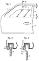
- a door 1 of a vehicle automobile having a frame 2 in which a window 4 slides under the action of a electric drive motor 6.
- the frame 2 of the door 1 is provided with a seal 8 in at least part of which a guide is arranged optical 10 consisting, for example, of a multimode optical fiber.
- the optical fiber 10 is associated with means for transmitting and receiving signals 12 and 14 respectively optics propagating inside said fiber 10. These means are adapted to control the operation of the window regulator mechanism or the anti-theft system of the vehicle they equip.
- the optical fiber 10 is placed in the seal 8 outside the window path 4.
- the window 4 going up under the action of its drive motor 6, if a finger 16 is wedged between said window 4 and the frame 2 of the door 1 (FIG. 3), the fiber lens 10 is crushed by finger 16.
- the optical fiber 10 deforms, which causes a local modification of its radius of curvature. This curvature causes a attenuation of the power of optical signals propagating in the fiber optical 10. This results in a drop in the amplitude of the electrical signals emitted by the receiver 14 to a central unit 18 which, in response to this drop, generates a signal to stop or reverse the direction of movement of the motor 6 driving the window 4.
- a pressure sensor designated as a whole by the general reference number 20, includes your multimode optical fiber 10 mentioned above which operates on the principle of intensity modulation of the light which propagates there according to the pressure applied.
- the sensor pressure 20 is associated with the transmission 12 and reception 14 means of the optical signals propagating inside said fiber 10.
- the pressure sensor 20 operates in transmission mode.
- Optical fiber 10 includes a part 10a which constitutes the sensitive element of the pressure 20, and a part 10b serving as a light transmission line.
- the emission means 12 inject a light signal at one end of the fiber 10.
- These emission means 12 comprise an optical source which is packaged so as to be fixedly attached to the optical fiber 10, this in order to avoid the use of too expensive optical connectors.
- Source optical will preferably be a light emitting diode.
- the light signal injected into the optical fiber 10 propagates to the detector 14 such that a photodiode also securely attached to the other end of said fiber 10.
- the light emitting diode and the photodiode are SMD (Surface Mount) Device), crimped in the same case also receiving the two ends of the optical fiber 10 forming the pressure sensor 20.
- the housing comprises on the other hand, connection means facilitating its mounting on a card electronic.
- the pressure sensor 20 can also operate in reflection mode.
- the source 12 and the receiver 14 are located at the same end of the fiber 10, while a reflector 11 reflecting the signals luminous is arranged at the other end of said fiber 10.
- the functions transmission and reception are preferably ensured by a diode laser with its own photodetector cell.
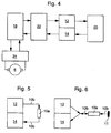
- a supply circuit 22 supplies the optical source 12 with current.
- This current can be continuous and / or variable periodically over time. According to a preferred characteristic of the invention, the current will be continuous during the periods of operation of the drive motor 6, and periodic rectangular shape during downtime.
- Circuit 22 also includes circuits for converting and amplifying currents from the detector 14.
- the safety device also comprises a circuit 24 of the drive motor 6.
- This control circuit 24 has a bridge type structure for bidirectional control of said motor 6. It can be made entirely from semiconductors or include Relays.
- MOS type transistors makes it possible to switch the relay with very low current, which improves the service life of components.
- Another advantage is that the same component MOS can be used as a current measurement element to limit this last, to detect the limit switches and protect the motor 6 against current peaks.
- This central unit 18 comprises a microcontroller and / or a microprocessor which manages the control, measurement and calibration of the pressure sensor 20 by means of programs and of computer algorithms implanted in a non-volatile memory accessible to said microcontroller.
- the central unit 18 has for this purpose means of analog-digital conversion. Control by the central unit 18 stop and run states as well as the direction of rotation of the motor drive 6 takes place via the control circuit 24. This last measurement and also transmits to the central unit 18 the variations of the supply current to motor 6 in order to detect the end positions of window stroke 4 and protect the electronics against current spikes resulting therefrom, as will be described in more detail later.
- the method is measures the frequency of the pulses caused by the switching of brushes such as 28 of the electric motor 6 driving the window 4, and we stop the drive of said window 4 when the frequency of the pulses is lower than a predetermined threshold frequency.
- these detection means comprise a MOS transistor 30 at the terminals of which the pulses caused by the switching of the brushes 28.
- the MOS transistor 30 further controls the switching of relays such as 32 of the motor electric 6, and therefore determines the direction of movement of the movable panel 4.
- the pulses collected at the terminals of the MOS transistor 30 then pass to through a filter 34, an amplifier 36, then are reshaped by means of a comparator 38. Finally, the pulses are sent to comparison means for comparing the frequency of the pulses at a threshold frequency. These means are constituted by the central unit 18 which calculates the pulse frequency and compares it to the stored threshold frequency in memory. Finally, when the pulse frequency becomes lower at the threshold frequency, the central unit 18 produces a second alarm signal which causes it to stop or reverse the running direction of the engine 6. It thus becomes possible to detect the limit switch or the presence of a foreign body such as, for example, an arm braking the movement of the window 4 and opposing its raising. The comparison of the frequency measured with a reference frequency therefore makes it possible to perform a predetection of obstacle and to avoid, in certain cases, the pinching. She also protects the drive motor 6 and its circuit control 24 against particularly harmful current peaks.
- the central unit 18 measures the frequency of the pulses caused by the switching of the brushes 28 of the drive motor 6 and deduces therefrom the speed of rotation of the rotor of said motor 6. Knowing the speed of rotation of the motor 6, the central unit 18 can calculate the stroke of the window 4 from a previously known reference position stored in memory. This reference position corresponds to the last calculated position of the window 4 before stopping the drive motor 6.
- the method of indirect determination of the position of the glass 4 described above however has a drawback. Indeed, when the glass 4 arrives in its end position and that its drive motor 6 stops, it is not possible to determine whether this stop is due to the the window 4 is in abutment against the frame 2 of the door 1 in which it slide, or if the stop is due to the presence of a foreign body trapped between the window 4 and the amount of said frame 2. This is why it is proposed to associate to the indirect type detection means direct detection means of the presence of a foreign body, these means comprising the pressure 20 to optical fiber 10 described above. So when closing the window 4, it can be deduced that in the absence of an alarm signal coming from the pressure sensor 20, the window 4 has reached the end stop race against the upright of frame 2, and that any risk of accident is avoided. Conversely, if the pressure sensor 20 produces an alarm signal, the unit control unit 18 immediately controls the reversal of the direction of travel of the drive motor 6.
- the present invention also aims to provide a sensor for pressure 20 retaining its original performance despite its sensitivity to disturbing physical quantities such as temperature and wear phenomena of the materials that constitute it.
- the central unit 18 notes the stopping of the drive motor 6, compare and correct the parameters of operation of the pressure sensor 20, taken under conditions of any environment, according to the same parameters of a standard sensor taken under known reference conditions stored in a non-volatile memory accessible to the microcontroller of said central unit 18.
- the operating parameters of the pressure 20 are measured and corrected repeatedly throughout the duration of the shutdown period of the drive motor 6. When refitting running of the drive motor 6, only the last corrections of the operating parameters of sensor 20 will be taken into account.
- the sensor detection circuit 20 is generally composed of a photodetector 14 followed by a circuit amplifier comprising an operational amplifier. Now everything photodetector presents a so-called dark current depending on its technology, its bias current and temperature. This current which fluctuates over time is amplified and contributes in part to the generation a parasitic offset voltage at the output. In addition, any amplifier operational presents a non-zero voltage and current offset signal, with more or less significant drift depending on the quality of the component and the temperature conditions.
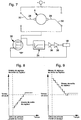
- the transmitter 12 is supplied by means of a periodic rectangular current obtained by superimposing on a constant current I O a small periodic variation ⁇ I O , so that the variation of the optical signal which results can be considered linear.
- the transmitter 12 is supplied by means of a periodic rectangular current obtained by superimposing on a direct current I O a small periodic variation ⁇ I O.
- This third calibration procedure requires a first calibration of the pressure sensor 20 which makes it possible to calculate the pressure applied as a function of the voltage measured by means of an approximation polynomial of degree 3 or 4. This method allows to perform simple corrections of the coefficients of the polynomial, or more corrections developed using specific algorithms.
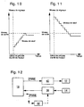
- the self-calibration method can use the variable bias current and threshold correction constant trigger illustrated in Figures 8 and 9.
- the threshold voltage of comparator 38 can here be fixed either by a circuit external to the microcontroller of the central unit 18, either by the microcontroller itself (by programming).
- the calibration method can use correction with variable trigger threshold and bias current fixed which is illustrated by Figures 10 and 11.
- the current polarization of the transmitter 12 is constant, and one increases or decreases, by example by step, the value of the threshold signal of comparator 38 which fixes the alarm threshold, until this value becomes substantially equal to the value of the output signal from the pressure sensor 20 (at the resolution near the system). Then the threshold is set to a known value lower than the signal exit.
- the microcontroller of the unit control unit 18 controls an external circuit to adjust the threshold level of alarm triggered.
- the advantage in this case is that it is not necessary to measure the output signal from the pressure sensor 20 (and therefore to equip the microcontroller with an analog / digital converter), which allows you to choose microcontroller components at low cost. But it is note that the threshold can also be set by programming. In this case, it an analog / digital converter is necessary to be able to communicate with the microcontroller. It should also be noted that all the self-calibration procedures that have been described in this patent can be combined with each other.
- the microcontroller of the central unit 18 not provided with an analog / digital converter, generates a rectangular PWM signal of fixed frequency, but with variable pulse durations. This is called pulse duration modulation or PWM (Pulse Width Modulation). Each duration value can be coded in four or eight bits or more by the microprocessor.
- the PWM signal is sent to an integrator 40 of the low-pass filter type which transforms the pulses into distinct voltage levels. It is thus possible, by varying the coding of the PWM signal, to program the form and the level of the bias current of the transmitter 12. It is also possible, if necessary, to modify by means of an integrator 42 the value of the signal comparator 38 which sets the alarm threshold.
- PFM Pulse Frequency Modulation
- coded pulse modulation Pulse Code Modulation
- the self-calibration procedure can be extended to the means of indirect system detection. Indeed, it has not been established that the indirect detection is always reliable over time. You have to expect that the performance of the drive motor 6 and the elements of transmission evolve over time. It is the same with friction of the window 4 against the gasket 8 which can evolve under the effect of deformations of frame 2 of door 1. Likewise, it is to be expected that that the movement of the glass changes according to the speed of movement of the vehicle. Failure to take these disturbance parameters into account could lead to a system malfunction. Monitoring and evaluation in the time of the stage speed of the window 4 in the area where the movement of this is substantially uniform, for example by the method of averages slippery, could correct the calculation of the position of the glass 4, as well as the value of the threshold frequency for the detection of obstacles.
- the present invention also aims to provide a sensor for fiber optic pressure simple and inexpensive to manufacture.
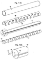
- the pressure sensor according to the invention includes a central core made of foam or rubber flexible which is in the form of a substantially cylindrical support 44 or elongated in polygonal section.
- a central core made of foam or rubber flexible which is in the form of a substantially cylindrical support 44 or elongated in polygonal section.
- two grooves such as 46 diametrically opposite which extend parallel to the longitudinal axis of said support 44 and in which the optical fiber 10 is housed without constraint (see Figure 13b which is a detailed view of the region of FIG. 13a surrounded by a line mixed).
- the cylindrical support 44 and its optical fiber 10 are inserted into a envelope 48 split longitudinally and made, for example, in a thin and hard plastic material from which a plurality have been cut clamping jaws such as 50. These jaws 50 are used for bending the optical fiber 10 by elastic pressure and to locally modify its radius curvature.
- the pressure sensor thus formed is finally wrapped in a sheath 52 made of a foam or a very flexible material.
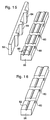
- the central core of the pressure sensor according to the invention can be produced in the form of a support 54 formed of a periodic succession of frustoconical elements along from which the optical fiber 10 is fixed. This form of execution has the merit improve the sensitivity of the sensor by creating initial micro-bends.
- the fiber optic 10 is mounted directly on the inner face of the jaws 50 of the casing 48.
- the free end of said jaws 50 is slightly bent to hold and guide the optical fiber 10 along envelope 48.
- This embodiment has the advantage of maintaining the 10 straight fiber optic. It has been found that the more the optical fiber used in such sensors is curved, the shorter the service life of said sensors.
- the optical fiber 10 is sandwiched between a first and a second bands 56 and 58 respectively made from two materials elastomers of the same type but of different hardnesses.
- the first strip 56 made from a relatively hard material, has a succession of transverse cavities such as 60 regularly distributed on along said strip 56.
- the upper face of the strip 56 has two grooves such that 62 in which the optical fiber 10 is housed. These grooves 62 are arranged parallel to and on either side of the axis of symmetry longitudinal of the strip 56 and have a V or semi-circular profile.
- the cavities 60 of the first strip 56 are partially or totally filled by studs such as 64 having a shape complementary to that of said cavities 60 and arranged on the underside of the second strip 58.
- the elastomeric material used to make the second strip 58 is same type as that used for the first band 56, but has a significantly lower hardness. So the first and second bands 56 and 58 are complementary both by the geometric shape and by the alternation in hardness of the materials.
- the optical fiber 10 is housed between the two bands 56 and 58 and can keep a straight profile or be slightly and periodically curved. In the case of operation in reflection mode, only one groove 62 is necessary (FIG. 16).
- the second strip 58 may be flat, produced by means of a certain thickness of a substantially soft elastomeric material.
- the spacing of the jaws 50 or the cavities 60 defines the period of microbending.
- the micro-curvature period will be chosen so as to obtain a strong coupling between the modes guided in the core of the optical fiber 10, and the modes radiated by the sheath.
- T is the modulus of the wave vector
- ⁇ and n c are the radius and the refractive index of the core of the fiber 10, respectively
- ⁇ is the relative difference between the core and cladding indices of the optical fiber 10.
- the optimal micro-curvature period must be a multiple of the period T given by the relation: T ⁇ ⁇ 2 ⁇ where p and ⁇ are respectively the core radius of the fiber 10 and the relative difference between the core and cladding indices of the optical fiber 10.
- Pressure sensitivity being greater in the case of fibers with index gradient, it is this type of fiber which will be chosen preferably.
- the optical fiber 10 can be of the plastic type, entirely made of polymer materials.
Landscapes
- Physics & Mathematics (AREA)
- General Physics & Mathematics (AREA)
- Power-Operated Mechanisms For Wings (AREA)
Priority Applications (7)
| Application Number | Priority Date | Filing Date | Title |
|---|---|---|---|
| EP98123825A EP1011184A1 (de) | 1998-12-15 | 1998-12-15 | Sicherheitsvorrichtung für einen elektromotorischen Fensterheber und Verfahren zur Ausführung dieser Vorrichtung |
| DE69917485T DE69917485T2 (de) | 1998-12-15 | 1999-12-15 | Schutzvorrichtung für ein von einem elektromotor angetriebenen schiebefenster und installationsverfahren einer solchen vorrichtung |
| PCT/EP1999/009965 WO2000036725A1 (fr) | 1998-12-15 | 1999-12-15 | Dispositif de securite associe a un panneau coulissant entraine par un moteur electrique et procede de mise en oeuvre d'un tel dispositif |
| US09/460,969 US6772559B1 (en) | 1998-12-15 | 1999-12-15 | Safety device for a sliding panel driven by an electrical motor and method for implementing such a device |
| ES99964578T ES2222048T3 (es) | 1998-12-15 | 1999-12-15 | Dispositivo de seguridad asociado a un panel deslizante accionado por un motor electrico y procedimiento de realizacion de tal dispositivo. |
| EP99964578A EP1142077B1 (de) | 1998-12-15 | 1999-12-15 | Schutzvorrichtung für ein von einem elektromotor angetriebenen schiebefenster und installationsverfahren einer solchen vorrichtung |
| US10/742,777 US7307395B2 (en) | 1998-12-15 | 2003-12-23 | Safety device for a sliding panel driven by an electrical motor and method for implementing such a device |
Applications Claiming Priority (1)
| Application Number | Priority Date | Filing Date | Title |
|---|---|---|---|
| EP98123825A EP1011184A1 (de) | 1998-12-15 | 1998-12-15 | Sicherheitsvorrichtung für einen elektromotorischen Fensterheber und Verfahren zur Ausführung dieser Vorrichtung |
Publications (1)
| Publication Number | Publication Date |
|---|---|
| EP1011184A1 true EP1011184A1 (de) | 2000-06-21 |
Family
ID=8233140
Family Applications (2)
| Application Number | Title | Priority Date | Filing Date |
|---|---|---|---|
| EP98123825A Withdrawn EP1011184A1 (de) | 1998-12-15 | 1998-12-15 | Sicherheitsvorrichtung für einen elektromotorischen Fensterheber und Verfahren zur Ausführung dieser Vorrichtung |
| EP99964578A Expired - Lifetime EP1142077B1 (de) | 1998-12-15 | 1999-12-15 | Schutzvorrichtung für ein von einem elektromotor angetriebenen schiebefenster und installationsverfahren einer solchen vorrichtung |
Family Applications After (1)
| Application Number | Title | Priority Date | Filing Date |
|---|---|---|---|
| EP99964578A Expired - Lifetime EP1142077B1 (de) | 1998-12-15 | 1999-12-15 | Schutzvorrichtung für ein von einem elektromotor angetriebenen schiebefenster und installationsverfahren einer solchen vorrichtung |
Country Status (5)
| Country | Link |
|---|---|
| US (2) | US6772559B1 (de) |
| EP (2) | EP1011184A1 (de) |
| DE (1) | DE69917485T2 (de) |
| ES (1) | ES2222048T3 (de) |
| WO (1) | WO2000036725A1 (de) |
Cited By (3)
| Publication number | Priority date | Publication date | Assignee | Title |
|---|---|---|---|---|
| FR2845723A1 (fr) * | 2002-10-09 | 2004-04-16 | Cafac | Bord securite pour portes automatiques, notamment portes de vehicule ferroviaire |
| EP1575068A3 (de) * | 2004-02-25 | 2007-05-16 | HÜBNER GmbH | Fingerschutzprofil |
| EP3296177A1 (de) * | 2016-09-19 | 2018-03-21 | Gebr. Bode GmbH & Co. KG | Zugangssteuersystem für eine zugangsvorrichtung eines fahrzeugs |
Families Citing this family (46)
| Publication number | Priority date | Publication date | Assignee | Title |
|---|---|---|---|---|
| US7548037B2 (en) * | 1992-04-22 | 2009-06-16 | Nartron Corporation | Collision monitoring system |
| DE10132886A1 (de) | 2001-07-06 | 2003-01-16 | Bosch Gmbh Robert | Verfahren und Vorrichtung zum Öffnen und Schließen eines am Fahrzeug drehbar oder kippbar gelagerten Teils |
| US20050012484A1 (en) * | 2001-11-02 | 2005-01-20 | Carl Gifford | Multizone capacitive anti-pinch system |
| JP3831325B2 (ja) * | 2002-10-01 | 2006-10-11 | アスモ株式会社 | 開閉装置 |
| WO2005096022A1 (ja) * | 2004-03-30 | 2005-10-13 | Aisin Seiki Kabushiki Kaisha | 状態検知センサ |
| DE102004022807A1 (de) * | 2004-05-08 | 2005-12-01 | Conti Temic Microelectronic Gmbh | Verfahren zur elektrischen Steuerung und Regelung der Bewegung eines elektrisch betriebenen Aggregats, insbesondere eines Fensterhebers oder Schiebedachs eines Kraftfahrzeugs |
| FR2871581B1 (fr) * | 2004-06-15 | 2006-09-08 | Arvinmeritor Light Vehicle Sys | Systeme de detection d'un obstacle et procede de detection d'un obstacle |
| DE102005057904B4 (de) * | 2004-12-02 | 2009-05-07 | Alps Electric Co., Ltd. | Elektrische Fensterhebeanlage mit Einklemm-Erkennungsfunktion |
| DE102005005185B4 (de) * | 2005-02-03 | 2007-04-12 | Daimlerchrysler Ag | Schaltanordnung für ein Schaltelement zum Öffnen und Schließen eines Fahrzeugflügels |
| JP2006306155A (ja) * | 2005-04-26 | 2006-11-09 | Denso Corp | 車両用衝突検知システム |
| DE202005011044U1 (de) * | 2005-07-06 | 2006-11-16 | Brose Fahrzeugteile Gmbh & Co. Kommanditgesellschaft, Coburg | Sensorsystem für eine Einklemmschutzvorrichtung |
| ITTV20050169A1 (it) * | 2005-11-07 | 2007-05-08 | Nice Spa | Dispositivo di sicurezza per avvolgibili, tende solari, cancelli o simili. |
| US7688013B2 (en) * | 2006-06-21 | 2010-03-30 | Flextronics Automotive Inc. | System and method for controlling speed of a closure member |
| US7479748B2 (en) * | 2006-10-25 | 2009-01-20 | Robert Bosch Gmbh | Systems and methods of tracking partition system performance |
| US9174597B2 (en) * | 2007-04-25 | 2015-11-03 | Ford Global Technologies, Llc | Electro-mechanical protector for vehicle latches during crash conditions and method for operating the same |
| DE102007021285B3 (de) * | 2007-05-07 | 2008-10-16 | Continental Automotive Gmbh | Verfahren und Einrichtung zum Betreiben einer elektromechanischen Verstellvorrichtung |
| DE102007045986A1 (de) * | 2007-09-26 | 2009-04-23 | Continental Automotive Gmbh | Verfahren und Vorrichtung zur Reversiererkennung bei einer elektrischen Betätigungseinheit eines Fahrzeugs |
| KR101476859B1 (ko) | 2008-03-26 | 2014-12-24 | 엘지전자 주식회사 | 냉장고의 드로어 구동 시스템 및 구동 제어 방법 |
| KR101441133B1 (ko) * | 2008-03-26 | 2014-09-17 | 엘지전자 주식회사 | 냉장고의 드로어 구동 제어 방법 |
| WO2009119922A1 (en) * | 2008-03-26 | 2009-10-01 | Lg Electronics Inc. | Refrigerator |
| WO2009119924A1 (en) * | 2008-03-26 | 2009-10-01 | Lg Electronics Inc. | Refrigerator, system and method for driving a drawer of the refrigerator |
| KR101380557B1 (ko) * | 2008-03-26 | 2014-04-01 | 엘지전자 주식회사 | 냉장고의 드로어 구동 시스템 및 제어 방법 |
| US8217613B2 (en) * | 2008-03-26 | 2012-07-10 | Lg Electronics Inc. | System and method for driving a drawer of a refrigerator and refrigerator employing same |
| KR101505691B1 (ko) | 2008-03-26 | 2015-03-24 | 엘지전자 주식회사 | 냉장고의 드로어 구동 시스템 및 구동 제어 방법 |
| JP5139164B2 (ja) * | 2008-06-10 | 2013-02-06 | オークマ株式会社 | 位置制御装置 |
| US8373550B2 (en) * | 2008-08-20 | 2013-02-12 | Control Solutions LLC | Door assist system controller and method |
| KR101592575B1 (ko) * | 2009-03-20 | 2016-02-05 | 엘지전자 주식회사 | 냉장고 |
| KR101592572B1 (ko) * | 2009-03-20 | 2016-02-05 | 엘지전자 주식회사 | 냉장고 및 그 제어 방법 |
| KR101592573B1 (ko) * | 2009-03-20 | 2016-02-05 | 엘지전자 주식회사 | 냉장고 |
| KR101592571B1 (ko) | 2009-03-20 | 2016-02-05 | 엘지전자 주식회사 | 냉장고 및 그 제어 방법 |
| KR101592574B1 (ko) * | 2009-03-20 | 2016-02-05 | 엘지전자 주식회사 | 냉장고 및 그 제어 방법 |
| US9234979B2 (en) | 2009-12-08 | 2016-01-12 | Magna Closures Inc. | Wide activation angle pinch sensor section |
| US8493081B2 (en) | 2009-12-08 | 2013-07-23 | Magna Closures Inc. | Wide activation angle pinch sensor section and sensor hook-on attachment principle |
| EP2657442A4 (de) * | 2010-12-24 | 2017-12-13 | RiB Laboratory, Inc | Einklemmungserkennungsvorrichtung für öffnungs/schliessabschnitt, fahrzeug damit und einklemmungserkennungsverfahren für öffnungs/schliessabschnitt |
| DE102010064213A1 (de) * | 2010-12-27 | 2012-06-28 | Robert Bosch Gmbh | Verfahren und Vorrichtung zum Bereitstellen einer Bewegungsangabe, insbesondere für eine Blockiererkennung eines Schließsystems |
| DE102011112321B3 (de) | 2011-09-02 | 2012-08-02 | Audi Ag | Beleuchtungsvorrichtung zum Erzeugen eines Leuchtstreifens sowie Kraftwagen |
| DE102011112320B3 (de) | 2011-09-02 | 2012-08-02 | Audi Ag | Umlaufende Beleuchtungsvorrichtung für eine Fahrzeug-Komponente |
| DE102011112322B4 (de) | 2011-09-02 | 2014-03-27 | Audi Ag | Beleuchtungsvorrichtung zum Erzeugen eines Leuchtstreifens sowie Kraftwagen |
| US8615927B2 (en) * | 2011-11-23 | 2013-12-31 | GM Global Technology Operations LLC | Noncontact obstacle detection system using RFID technology |
| US20140033120A1 (en) * | 2012-07-26 | 2014-01-30 | David BENTAL | System and methods for presenting market analyses using intuitive information presentation |
| DE102012215214B4 (de) * | 2012-08-28 | 2014-11-27 | Continental Automotive Gmbh | Verfahren und Vorrichtung zur Bestimmung der Position eines motorgetriebenen Stellteils |
| DE102013015119A1 (de) * | 2013-09-12 | 2015-03-12 | Brose Fahrzeugteile Gmbh & Co. Kommanditgesellschaft, Hallstadt | Stellvorrichtung zur Verstellung eines zwischen einer Schließstellung und einer Offenstellung verstellbaren Fahrzeugteils |
| JP6471475B2 (ja) * | 2014-11-26 | 2019-02-20 | アイシン精機株式会社 | 車両用開閉部材の制御装置及び制御方法 |
| JP6634345B2 (ja) * | 2016-05-31 | 2020-01-22 | 株式会社ミツバ | タッチセンサユニット |
| EP3940910B1 (de) * | 2020-07-16 | 2025-06-25 | Inalfa Roof Systems Group B.V. | Verfahren und system zur hinderniserkennung |
| KR102846690B1 (ko) * | 2020-08-12 | 2025-08-18 | 현대자동차주식회사 | 윈도우 제어 장치 및 그의 윈도우 제어 방법 |
Citations (9)
| Publication number | Priority date | Publication date | Assignee | Title |
|---|---|---|---|---|
| GB2125572A (en) * | 1982-08-03 | 1984-03-07 | Standard Telephones Cables Ltd | Optical fibre sensors |
| US4870333A (en) | 1986-10-03 | 1989-09-26 | Jidosha Denki Kogyo Kabushiki Kaisha | Automatic opening and closing device for a window |
| EP0345914A1 (de) * | 1988-06-08 | 1989-12-13 | Kabushiki Kaisha Riken | Motorisch betriebene Öffnungs-/Schliessvorrichtung für ein Fenster oder eine Tür |
| EP0419267A1 (de) * | 1989-09-21 | 1991-03-27 | Herga Electric Limited | Erfassung und Messung von Signalen in faseroptischen Systemen |
| DE4030607A1 (de) * | 1990-09-27 | 1992-04-16 | Siemens Ag | Nach dem radarprinzip konzipiertes ueberwachungssystem zur ueberwachung eines objektes |
| DE4416803A1 (de) * | 1993-05-15 | 1994-11-17 | Brose Fahrzeugteile | Verfahren und Vorrichtung zum Verstellen fremdkraftbetätigter Teile, insbesondere in einer Fahrzeugkarosserie |
| US5428923A (en) * | 1991-02-25 | 1995-07-04 | Gmi Holdings, Inc. | Fail safe obstruction detector for door operators and door operator system incorporating such detector |
| DE4423104A1 (de) * | 1994-07-01 | 1996-01-04 | Leon Helma Christina | Druckempfindliche Sensorvorrichtung mit Lichtwellenleiter |
| DE19724952A1 (de) * | 1996-06-13 | 1997-12-18 | Asmo Co Ltd | Fremdkraftbetätigte Fenstervorrichtung mit Sensor-Fehlfunktionserfassung |
Family Cites Families (17)
| Publication number | Priority date | Publication date | Assignee | Title |
|---|---|---|---|---|
| DE1962340A1 (de) | 1969-12-12 | 1971-06-16 | Reuss & Co | Abstandhalter fuer Bewehrungsstaebe |
| DE3809957A1 (de) * | 1988-03-24 | 1989-10-05 | Felten & Guilleaume Energie | Lichtwellenleiter-sensor fuer druckkraefte und seine verwendung |
| DE3911493A1 (de) | 1989-04-08 | 1990-10-11 | Bayerische Motoren Werke Ag | Sicherheitseinrichtung fuer motorisch bewegte schliessteile |
| US5051672A (en) | 1989-04-28 | 1991-09-24 | Kabushiki Kaisha Riken | Automatic window/door system |
| DE4030904A1 (de) | 1990-09-29 | 1992-04-02 | Siemens Ag | Verfahren zur herstellung eines karbonatschmelzen-brennstoffzellenstapels |
| US5404673A (en) * | 1992-06-26 | 1995-04-11 | Koito Manufacturing Co., Ltd. | Power window apparatus with safety device |
| JP3253031B2 (ja) | 1993-01-21 | 2002-02-04 | 自動車電機工業株式会社 | パワーウインド装置のモータ制御方法および装置 |
| DE4330904A1 (de) | 1993-09-11 | 1995-03-16 | Teves Gmbh Alfred | Sicherheitsvorrichtung für bewegliche Teile |
| DE4331781C2 (de) * | 1993-09-18 | 2003-11-27 | Somfy Feinmech & Elektrotech | Steuervorrichtung für einen Antriebsmotor zum Bewegen eines entlang einer bestimmten Bahn zwischen zwei Endstellungen geführten Tors, insbesondere eines Garagentors |
| US5392931A (en) * | 1993-09-30 | 1995-02-28 | Beloit Technologies, Inc. | Adjustable bar screen |
| DE19681199B4 (de) * | 1995-12-04 | 2008-02-21 | Hitachi Cable, Ltd. | Druckschalter |
| JPH09288931A (ja) * | 1996-04-22 | 1997-11-04 | Asmo Co Ltd | コードスイッチ |
| JP3834909B2 (ja) * | 1996-04-23 | 2006-10-18 | アスモ株式会社 | 車両用動力付窓開閉装置 |
| DE19623420A1 (de) * | 1996-06-12 | 1997-12-18 | Bosch Gmbh Robert | Vorrichtung zur elektronischen Überwachung eines in einem Fahrzeug angeordneten Verstellantriebs |
| CA2228377C (en) * | 1997-03-03 | 2001-01-30 | Asmo Co., Ltd. | Vehicle window control system responsive to external force |
| JP4245094B2 (ja) * | 1998-02-25 | 2009-03-25 | ダウマル カステリョン メルチョール | 自動車の窓ガラスの自動昇降装置における障害物検知システム |
| US7030766B2 (en) * | 2003-06-18 | 2006-04-18 | Edwards Systems Technology, Inc. | Ambient condition detector with multi-function test |
-
1998
- 1998-12-15 EP EP98123825A patent/EP1011184A1/de not_active Withdrawn
-
1999
- 1999-12-15 ES ES99964578T patent/ES2222048T3/es not_active Expired - Lifetime
- 1999-12-15 EP EP99964578A patent/EP1142077B1/de not_active Expired - Lifetime
- 1999-12-15 WO PCT/EP1999/009965 patent/WO2000036725A1/fr not_active Ceased
- 1999-12-15 US US09/460,969 patent/US6772559B1/en not_active Expired - Fee Related
- 1999-12-15 DE DE69917485T patent/DE69917485T2/de not_active Expired - Lifetime
-
2003
- 2003-12-23 US US10/742,777 patent/US7307395B2/en not_active Expired - Fee Related
Patent Citations (9)
| Publication number | Priority date | Publication date | Assignee | Title |
|---|---|---|---|---|
| GB2125572A (en) * | 1982-08-03 | 1984-03-07 | Standard Telephones Cables Ltd | Optical fibre sensors |
| US4870333A (en) | 1986-10-03 | 1989-09-26 | Jidosha Denki Kogyo Kabushiki Kaisha | Automatic opening and closing device for a window |
| EP0345914A1 (de) * | 1988-06-08 | 1989-12-13 | Kabushiki Kaisha Riken | Motorisch betriebene Öffnungs-/Schliessvorrichtung für ein Fenster oder eine Tür |
| EP0419267A1 (de) * | 1989-09-21 | 1991-03-27 | Herga Electric Limited | Erfassung und Messung von Signalen in faseroptischen Systemen |
| DE4030607A1 (de) * | 1990-09-27 | 1992-04-16 | Siemens Ag | Nach dem radarprinzip konzipiertes ueberwachungssystem zur ueberwachung eines objektes |
| US5428923A (en) * | 1991-02-25 | 1995-07-04 | Gmi Holdings, Inc. | Fail safe obstruction detector for door operators and door operator system incorporating such detector |
| DE4416803A1 (de) * | 1993-05-15 | 1994-11-17 | Brose Fahrzeugteile | Verfahren und Vorrichtung zum Verstellen fremdkraftbetätigter Teile, insbesondere in einer Fahrzeugkarosserie |
| DE4423104A1 (de) * | 1994-07-01 | 1996-01-04 | Leon Helma Christina | Druckempfindliche Sensorvorrichtung mit Lichtwellenleiter |
| DE19724952A1 (de) * | 1996-06-13 | 1997-12-18 | Asmo Co Ltd | Fremdkraftbetätigte Fenstervorrichtung mit Sensor-Fehlfunktionserfassung |
Cited By (3)
| Publication number | Priority date | Publication date | Assignee | Title |
|---|---|---|---|---|
| FR2845723A1 (fr) * | 2002-10-09 | 2004-04-16 | Cafac | Bord securite pour portes automatiques, notamment portes de vehicule ferroviaire |
| EP1575068A3 (de) * | 2004-02-25 | 2007-05-16 | HÜBNER GmbH | Fingerschutzprofil |
| EP3296177A1 (de) * | 2016-09-19 | 2018-03-21 | Gebr. Bode GmbH & Co. KG | Zugangssteuersystem für eine zugangsvorrichtung eines fahrzeugs |
Also Published As
| Publication number | Publication date |
|---|---|
| WO2000036725A1 (fr) | 2000-06-22 |
| DE69917485T2 (de) | 2005-05-12 |
| DE69917485D1 (de) | 2004-06-24 |
| ES2222048T3 (es) | 2005-01-16 |
| US6772559B1 (en) | 2004-08-10 |
| US7307395B2 (en) | 2007-12-11 |
| EP1142077B1 (de) | 2004-05-19 |
| US20040138843A1 (en) | 2004-07-15 |
| EP1142077A1 (de) | 2001-10-10 |
Similar Documents
| Publication | Publication Date | Title |
|---|---|---|
| EP1142077B1 (de) | Schutzvorrichtung für ein von einem elektromotor angetriebenen schiebefenster und installationsverfahren einer solchen vorrichtung | |
| EP1848363B1 (de) | Zahnbehandlungsvorrichtung mit automatischer einsatzerkennung | |
| WO2010009951A1 (fr) | Capteur a fibre optique auto-reference a diffusion brillouin stimulee | |
| FR2723448A1 (fr) | Dispositif de detection d'eau ou analogue sur une glace de vehicule automobile | |
| EP3598246B1 (de) | Armbanduhr, die eine messvorrichtung des relativen feuchtigkeitsgrads im innern ihres gehäuses umfasst | |
| EP1565717A2 (de) | Optische vorrichtung zum feststellen der anwesenheit von gasblasen in einer flüssigkeit | |
| FR2775313A1 (fr) | Systeme anticoincement perfectionne, base sur la modification de la conductivite lumineuse d'une fibre optique, pour leve-vitres destines a l'automobile | |
| FR2732927A1 (fr) | Coulisse, son procede de realisation et leve-vitre comportant une telle coulisse | |
| EP0573388A1 (de) | Einrichtung zur Erzeugung charakteristischer Signale der Verschiebung eines Verschlussmittels | |
| EP4052023A1 (de) | Vorrichtung und system zum messen von biologischen informationen | |
| FR2821879A1 (fr) | Dispositif anti-pincement de leve-vitre a cable | |
| FR2685503A1 (fr) | Panneau transparent mobile. | |
| FR2691543A1 (fr) | Appareil de mesure de la qualité de la viande. | |
| WO2000037292A1 (fr) | Procede de commande de nettoyage d'une surface de plaque par controle optique dynamique, et equipement de mise en oeuvre | |
| WO2020016490A1 (fr) | Dispositif de guidage et contrôle de tension d'un élément flexible filiforme tel qu'un câble électrique | |
| FR2741963A1 (fr) | Capteur optique realise selon la technique de l'optique integree et forme a base de polymeres | |
| FR2547049A1 (fr) | Dispositif de telemesure par polarimetrie | |
| EP0943906B1 (de) | Faseroptischer Kraftsensor, seine Herstellung und zugehörige Detektionseinrichtung | |
| EP1243808A1 (de) | Verschleisssensor für einen Reibbelag sowie Verfahren zur Verschleissmessung mit einem solchen Sensor | |
| EP0211804A1 (de) | Fiberoptisches Detektionssystem mit einverleibtem intensitätsmodulierten Sensor | |
| FR3098294A1 (fr) | Dispositif de mesure de l’écartement de deux éléments d’un appareil tendeur d’une caténaire | |
| EP0940662B1 (de) | Faseroptische Sonde | |
| EP1818498A2 (de) | Motorisierter Rolladen mit Vorrichtung zum Abschalten eines Motorantriebes bei Erkennung eines Hindernisses | |
| FR2591167A1 (fr) | Dispositifs de commande d'essuie-glaces, et de facon plus generale les detecteurs de transparence d'une paroi | |
| FR2775351A1 (fr) | Dispositif de determination de la presence ou de l'absence d'un bouchon en position correcte d'obturation d'une extremite de tubulure |
Legal Events
| Date | Code | Title | Description |
|---|---|---|---|
| PUAI | Public reference made under article 153(3) epc to a published international application that has entered the european phase |
Free format text: ORIGINAL CODE: 0009012 |
|
| AK | Designated contracting states |
Kind code of ref document: A1 Designated state(s): AT BE CH CY DE DK ES FI FR GB GR IE IT LI LU MC NL PT SE |
|
| AX | Request for extension of the european patent |
Free format text: AL;LT;LV;MK;RO;SI |
|
| STAA | Information on the status of an ep patent application or granted ep patent |
Free format text: STATUS: THE APPLICATION HAS BEEN WITHDRAWN |
|
| 17P | Request for examination filed |
Effective date: 20001221 |
|
| AKX | Designation fees paid |
Free format text: AT BE CH CY DE DK ES FI FR GB GR IE IT LI LU MC NL PT SE |
|
| 18W | Application withdrawn |
Withdrawal date: 20010125 |