EP1011184A1 - Safety device for an electric motor-driven sliding panel and method for carrying out this arrangement - Google Patents
Safety device for an electric motor-driven sliding panel and method for carrying out this arrangement Download PDFInfo
- Publication number
- EP1011184A1 EP1011184A1 EP98123825A EP98123825A EP1011184A1 EP 1011184 A1 EP1011184 A1 EP 1011184A1 EP 98123825 A EP98123825 A EP 98123825A EP 98123825 A EP98123825 A EP 98123825A EP 1011184 A1 EP1011184 A1 EP 1011184A1
- Authority
- EP
- European Patent Office
- Prior art keywords
- signal
- pressure sensor
- optical fiber
- frequency
- movable panel
- Prior art date
- Legal status (The legal status is an assumption and is not a legal conclusion. Google has not performed a legal analysis and makes no representation as to the accuracy of the status listed.)
- Withdrawn
Links
- 238000000034 method Methods 0.000 title claims description 67
- 239000013307 optical fiber Substances 0.000 claims abstract description 57
- 238000005259 measurement Methods 0.000 claims abstract description 20
- 239000000835 fiber Substances 0.000 claims description 53
- 230000003287 optical effect Effects 0.000 claims description 20
- 238000012937 correction Methods 0.000 claims description 19
- 238000001514 detection method Methods 0.000 claims description 19
- 230000000737 periodic effect Effects 0.000 claims description 15
- 230000005540 biological transmission Effects 0.000 claims description 13
- 230000035945 sensitivity Effects 0.000 claims description 13
- 230000006870 function Effects 0.000 claims description 10
- 230000008569 process Effects 0.000 claims description 10
- 230000001902 propagating effect Effects 0.000 claims description 9
- 230000007423 decrease Effects 0.000 claims description 6
- 230000004044 response Effects 0.000 claims description 6
- 238000005253 cladding Methods 0.000 claims description 4
- 239000013536 elastomeric material Substances 0.000 claims description 4
- 230000007613 environmental effect Effects 0.000 claims description 4
- 230000010287 polarization Effects 0.000 claims description 4
- 238000009530 blood pressure measurement Methods 0.000 claims description 3
- 230000000295 complement effect Effects 0.000 claims description 3
- 239000004033 plastic Substances 0.000 claims description 3
- 230000003247 decreasing effect Effects 0.000 claims description 2
- 230000003252 repetitive effect Effects 0.000 claims 1
- 238000006073 displacement reaction Methods 0.000 abstract 1
- 239000000463 material Substances 0.000 description 11
- 239000011521 glass Substances 0.000 description 10
- 230000008901 benefit Effects 0.000 description 5
- 230000000694 effects Effects 0.000 description 5
- 238000002347 injection Methods 0.000 description 5
- 239000007924 injection Substances 0.000 description 5
- 230000009471 action Effects 0.000 description 4
- 238000004519 manufacturing process Methods 0.000 description 4
- 208000031968 Cadaver Diseases 0.000 description 3
- 238000004422 calculation algorithm Methods 0.000 description 3
- 239000006185 dispersion Substances 0.000 description 3
- 235000019589 hardness Nutrition 0.000 description 3
- 238000012986 modification Methods 0.000 description 3
- 230000004048 modification Effects 0.000 description 3
- 230000003750 conditioning effect Effects 0.000 description 2
- 230000001186 cumulative effect Effects 0.000 description 2
- 229920001971 elastomer Polymers 0.000 description 2
- 239000006260 foam Substances 0.000 description 2
- 239000000243 solution Substances 0.000 description 2
- 238000012546 transfer Methods 0.000 description 2
- 230000005355 Hall effect Effects 0.000 description 1
- 230000006978 adaptation Effects 0.000 description 1
- 238000004026 adhesive bonding Methods 0.000 description 1
- 238000005452 bending Methods 0.000 description 1
- 230000002457 bidirectional effect Effects 0.000 description 1
- 238000004364 calculation method Methods 0.000 description 1
- 230000008859 change Effects 0.000 description 1
- 238000006243 chemical reaction Methods 0.000 description 1
- 239000011248 coating agent Substances 0.000 description 1
- 238000000576 coating method Methods 0.000 description 1
- 238000004590 computer program Methods 0.000 description 1
- 230000008878 coupling Effects 0.000 description 1
- 238000010168 coupling process Methods 0.000 description 1
- 238000005859 coupling reaction Methods 0.000 description 1
- 230000001419 dependent effect Effects 0.000 description 1
- 239000000806 elastomer Substances 0.000 description 1
- 238000005516 engineering process Methods 0.000 description 1
- 238000011156 evaluation Methods 0.000 description 1
- 238000009776 industrial production Methods 0.000 description 1
- 238000011031 large-scale manufacturing process Methods 0.000 description 1
- 230000007257 malfunction Effects 0.000 description 1
- 230000007246 mechanism Effects 0.000 description 1
- 238000012544 monitoring process Methods 0.000 description 1
- 210000000056 organ Anatomy 0.000 description 1
- 230000003071 parasitic effect Effects 0.000 description 1
- 238000005498 polishing Methods 0.000 description 1
- 229920000642 polymer Polymers 0.000 description 1
- 239000002861 polymer material Substances 0.000 description 1
- 238000003825 pressing Methods 0.000 description 1
- 238000012545 processing Methods 0.000 description 1
- 230000005855 radiation Effects 0.000 description 1
- 229920005989 resin Polymers 0.000 description 1
- 239000011347 resin Substances 0.000 description 1
- 230000000630 rising effect Effects 0.000 description 1
- 239000000523 sample Substances 0.000 description 1
- 239000004065 semiconductor Substances 0.000 description 1
- 230000003595 spectral effect Effects 0.000 description 1
- 238000001228 spectrum Methods 0.000 description 1
- 238000012360 testing method Methods 0.000 description 1
- 238000012549 training Methods 0.000 description 1
- 230000001960 triggered effect Effects 0.000 description 1
Images

Classifications
-
- G—PHYSICS
- G01—MEASURING; TESTING
- G01L—MEASURING FORCE, STRESS, TORQUE, WORK, MECHANICAL POWER, MECHANICAL EFFICIENCY, OR FLUID PRESSURE
- G01L1/00—Measuring force or stress, in general
- G01L1/24—Measuring force or stress, in general by measuring variations of optical properties of material when it is stressed, e.g. by photoelastic stress analysis using infrared, visible light, ultraviolet
- G01L1/242—Measuring force or stress, in general by measuring variations of optical properties of material when it is stressed, e.g. by photoelastic stress analysis using infrared, visible light, ultraviolet the material being an optical fibre
-
- E—FIXED CONSTRUCTIONS
- E05—LOCKS; KEYS; WINDOW OR DOOR FITTINGS; SAFES
- E05F—DEVICES FOR MOVING WINGS INTO OPEN OR CLOSED POSITION; CHECKS FOR WINGS; WING FITTINGS NOT OTHERWISE PROVIDED FOR, CONCERNED WITH THE FUNCTIONING OF THE WING
- E05F15/00—Power-operated mechanisms for wings
- E05F15/40—Safety devices, e.g. detection of obstructions or end positions
- E05F15/42—Detection using safety edges
- E05F15/43—Detection using safety edges responsive to disruption of energy beams, e.g. light or sound
- E05F15/431—Detection using safety edges responsive to disruption of energy beams, e.g. light or sound specially adapted for vehicle windows or roofs
-
- H—ELECTRICITY
- H02—GENERATION; CONVERSION OR DISTRIBUTION OF ELECTRIC POWER
- H02H—EMERGENCY PROTECTIVE CIRCUIT ARRANGEMENTS
- H02H7/00—Emergency protective circuit arrangements specially adapted for specific types of electric machines or apparatus or for sectionalised protection of cable or line systems, and effecting automatic switching in the event of an undesired change from normal working conditions
- H02H7/08—Emergency protective circuit arrangements specially adapted for specific types of electric machines or apparatus or for sectionalised protection of cable or line systems, and effecting automatic switching in the event of an undesired change from normal working conditions for dynamo-electric motors
- H02H7/085—Emergency protective circuit arrangements specially adapted for specific types of electric machines or apparatus or for sectionalised protection of cable or line systems, and effecting automatic switching in the event of an undesired change from normal working conditions for dynamo-electric motors against excessive load
- H02H7/0851—Emergency protective circuit arrangements specially adapted for specific types of electric machines or apparatus or for sectionalised protection of cable or line systems, and effecting automatic switching in the event of an undesired change from normal working conditions for dynamo-electric motors against excessive load for motors actuating a movable member between two end positions, e.g. detecting an end position or obstruction by overload signal
-
- E—FIXED CONSTRUCTIONS
- E05—LOCKS; KEYS; WINDOW OR DOOR FITTINGS; SAFES
- E05F—DEVICES FOR MOVING WINGS INTO OPEN OR CLOSED POSITION; CHECKS FOR WINGS; WING FITTINGS NOT OTHERWISE PROVIDED FOR, CONCERNED WITH THE FUNCTIONING OF THE WING
- E05F15/00—Power-operated mechanisms for wings
- E05F15/40—Safety devices, e.g. detection of obstructions or end positions
- E05F15/41—Detection by monitoring transmitted force or torque; Safety couplings with activation dependent upon torque or force, e.g. slip couplings
-
- E—FIXED CONSTRUCTIONS
- E05—LOCKS; KEYS; WINDOW OR DOOR FITTINGS; SAFES
- E05Y—INDEXING SCHEME ASSOCIATED WITH SUBCLASSES E05D AND E05F, RELATING TO CONSTRUCTION ELEMENTS, ELECTRIC CONTROL, POWER SUPPLY, POWER SIGNAL OR TRANSMISSION, USER INTERFACES, MOUNTING OR COUPLING, DETAILS, ACCESSORIES, AUXILIARY OPERATIONS NOT OTHERWISE PROVIDED FOR, APPLICATION THEREOF
- E05Y2900/00—Application of doors, windows, wings or fittings thereof
- E05Y2900/50—Application of doors, windows, wings or fittings thereof for vehicles
- E05Y2900/53—Type of wing
- E05Y2900/55—Windows
Definitions
- the present invention relates to a so-called mixed control method of a movable panel slidably driven by an electric motor, method in which the signal from a sensor is simultaneously exploited fiber optic pressure to stop and reverse the direction of the motor drive in case of variation of said signal, and the frequency measurement of pulses caused by the switching of the motor brushes training to perform an obstacle detection and to determine the end positions of the movable panel.
- the invention also relates to a safety device for such a mobile panel comprising means for detecting the presence of a foreign body slowing down the movement of said movable panel and opposing its complete closure.
- Another subject of the invention is a fiber optic force sensor usable in particular in safety devices of the aforementioned type.
- the invention finally aims to provide a method for calibrating the aforementioned force sensor allowing to increase the reliability of the operation of this sensor.
- More and more motor vehicles are equipped with window regulators electric, that is to say systems in which the windows are driven to sliding in the opening direction or in the closing direction by an electric motor whose operation is controlled by the driver of the vehicle by means of a manual switch.
- window regulators electric that is to say systems in which the windows are driven to sliding in the opening direction or in the closing direction by an electric motor whose operation is controlled by the driver of the vehicle by means of a manual switch.
- Such systems have enabled to make significant progress in terms of automotive safety, in the because the driver can easily open or close the windows while remaining attentive to traffic conditions and to driving his vehicle.
- these systems present significant reliability problems which are often linked to the appearance of twisted current peaks from an abrupt stop of the window drive motor.
- any obstacle to the advancement of the window produces, at the level of the motor, peaks of current which are generally harmful, especially for certain components such as control relays or switching transistors.
- Such peaks can appear, for example when the motorist continues to operate the switch that controls the operation of the drive motor when the window has already arrived in its closed position in which it is applied against the door frame.
- Current peaks can also appear when a foreign body, for example an arm, is in support on the edge of the glass and opposes the rise of the latter.
- a known solution consists in measuring the maximum level of the supply current supplied to the drive motor, and to block this current above a threshold predetermined. This measurement is generally carried out at the terminals of a switching transistor whose resistance varies from one component to another and remains dependent on the temperature. Other methods use precision resistors (current measurement) or Hall effect probes (measurement of magnetic fields), but the cost price of such components is high.
- Another order method consists in detecting the pulses caused by the switching of the brushes of the drive motor. These pulses are superimposed on the direct current consumption, and their frequency is proportional to the rotor speed.
- Such a technique is described in the American patent No 4,870,333 on behalf of the company Sidosha Denki Kogyo which offers a method of controlling an electric window regulator for a motor vehicle in which the number of pulses generated by the operation of the electric motor driving the window is recorded in a counter. When the number of pulses recorded in the counter reaches a value predetermined maximum, the control device that operates the system concludes that the window has reached the fully open position and causes stopping the drive motor.
- speed window ascension is not constant and depends on many parameters such as engine drive torque, friction between the glass and the door frame, the speed and trajectory of the vehicle etc.
- the position of the glass cannot therefore be calculated with a sufficient precision to be able to accurately determine when the window is completely closed.
- the drive motor can, by Therefore, be stopped on command of the control device before the window is not completely closed.
- the engine can continue to be supplied with current when the window is already completely closed, which produces harmful current peaks for the motor and electronics control.
- nothing in the Sidosha patent is provided for detect an overload before pinching which would prevent advancement of the glass.
- a safety device stops the drive or reverses the direction of ice movement.
- an electromagnetic waveguide by example an optical fiber
- a transmitter for example a laser diode injects a signal bright at one end of the fiber.
- This signal propagates to a receiver, for example a photodiode, placed at the other end of the fiber.
- the foreign body is entrained by the ice rising towards the seal and exerts pressure on the optical fiber.
- the optical fiber deforms, which causes a local modification of its radius of curvature.
- This change in the radius of curvature of the fiber causes significant losses, and consequently a decrease in amplitude of the optical signal received by the receiver.
- Safety devices of the kind described above which use sensors fiber optic pressure sensors as obstacle detectors have many drawbacks both in terms of their industrial production and level of their functioning at the user. These safety devices indeed, must be produced on a large scale to meet the needs of markets such as the automotive market. This therefore presupposes a process of simple and fast manufacturing with components and materials cheap. The same goes for test and calibration procedures which must be fast and allow the sensor to keep its operating characteristics over time. As we will see in the description which follows, it is difficult, under such conditions, to obtain products with homogeneous characteristics.
- a first problem is related to the fact that it is difficult to be able to have large quantities and at low cost of optical sources having little dispersed characteristics. This concerns in particular the power and the emission angle as well as the radiation spectrum of these sources.
- a second problem is related to the fact that the optical fiber used in the sensor must be fixed to the optical source either by means of connectors specific, or more simply by gluing. This requires several conditioning operations at the end of the fiber (stripping the coating, fracture or polishing), centering the fiber in relation to the optical source, and finally fixing by means of hardening resins fast. Large-scale production necessarily involves dispersal significant efficiency in the injection of power into the fiber, which affects the performance of the sensor.
- fiber optic sensors operate in their majority on the principle of losses induced by the variation of the radius of curvature of said fiber under the effect of pressure.
- the establishment of the fiber and conditioning of the sensitive part of the sensor therefore introduce necessarily a dispersion of the stresses in the optical fiber, which results in scattered sensor performance.
- the performance of the sensors strongly depend on the conditions under which they are used, and on their environment. This is the case, for example, in automotive applications where the sensors must operate within ambient temperature ranges between -40 ° C and + 85 ° C. It is clear that, under such conditions, the characteristics of certain components such as the optical source can remain constant (transmission power and spectral range). It the same is true for the power injection efficiency in the fiber which strongly depends on the thermal properties of the materials used for the source-fiber connection.
- the problem is even more important at the sensitive part of the sensor. Indeed, assuming that the optical fiber is not itself sensitive to temperature variations, the materials that serve as support and sheath, in general polymers, can be stressed thermal, which amounts to applying pressure variations on the fiber. These effects, to which is added the intrinsic sensitivity of optical fiber to temperature, can cause variations of more than 80% of the signal exit.
- the object of the present invention is to remedy the problems and disadvantages mentioned above by providing a reliable safety device for driving and closing sliding shutter panels electrically.
- the process of mixed detection according to the invention simultaneously makes it possible to increase the personal safety and effectively protect the electrical parts and electronic against overcurrents.
- the frequency of pulses caused by rotation of the electric motor driving the movable panel and we stop or reverse the direction of travel said motor when the frequency of these pulses becomes less than one predetermined threshold frequency.
- the position of reference is the last calculated position of the movable panel before stopping the drive motor.
- the measurement of the rotation speed of the drive motor allows calculate the travel of the movable panel from a reference position previously known.
- the indirect determination of the position of the window has a certain rate error.
- This error rate is cumulative. So after ten descent attempts and window lift, the cumulative difference between the calculated position and the position actual size of said window is of the order of one to two centimeters. That error remains low enough to define an end zone for lowering and raising movements of the window, zone wherein said window is in the vicinity of the door frame against which it should be applied.
- the delay time taken by the variation of the current with respect to the rotational speed of the motor is taken advantage of for limit overcurrents and to effectively protect the motor and its unit control.
- the invention also relates to a method for controlling a panel. mobile driven by sliding by an electric motor, characterized in that it consists in measuring the frequency of the impulses caused by the switching of the brushes of the electric motor driving the movable panel, and to stop or reverse the direction of travel of said motor when the frequency of these pulses becomes less than a predetermined threshold frequency.
- the frequency of the pulses being proportional to the speed of rotation of the rotor of the drive motor, it becomes possible to detect the presence of an obstacle slowing down the movement of the cover panel and opposing its rise. This is the case, for example, of the action of an arm placed on the edge of a window of a motor vehicle.
- the comparison of the speed measured with a reference speed therefore makes it possible to perform a obstacle detection and in certain cases to avoid pinching. She also significantly reduces the current peaks which are particularly harmful, especially for control electronics of the drive motor.
- the invention also relates to a security device comprising means for detecting the presence of a foreign body slowing the movement of a movable panel driven by sliding by a motor electric and opposing its closure, characterized in that said means are of the indirect type, based on the measurement of the frequency of pulses caused by the switching of the brushes of the electric motor.
- Another object of the present invention is to provide a sensor for fiber optic pressure usable as an obstacle detector retaining its original calibration despite its sensitivity to physical quantities disturbing factors such as temperature and wear phenomena materials that make it up.
- the invention also relates to a calibration method a fiber optic pressure sensor used as an obstacle detector in a sliding sliding panel drive system electrically, the sensor comprising an electrically powered transmitter which injects a light signal into an optical fiber, the light signal propagating to a transmitting receiver in response to the light signal transmitted by optical fiber, an electrical signal to a central microcontroller and / or microprocessor control which analyzes information from said receiver and allows, in the event of an incident, to stop or reverse the direction of travel of an electric motor driving the movable panel, the method being characterized in that, during the periods where we note the stopping of the motor for driving the movable panel, we compare and correct the operating parameters of the pressure, taken under any environmental conditions, depending of the same parameters of a standard sensor taken under conditions of known reference stored in a non-volatile memory accessible to the microcontroller and / or to the microprocessor of the control unit.
- the calibration procedure of the pressure starts as soon as the panel drive motor stops mobile is found.
- the operating parameters of the sensor are measured and corrected repeatedly throughout the duration of the stopping period of said drive motor. During the periods of engine operation, only the last corrections of the pressure sensor operating parameters stored in memory will be taken into account. Pressure sensor performance can thus be preserved, despite the phenomena of wear and the existence of disturbing physical quantities to which the sensor is sensitive.
- Yet another object of the present invention is to provide a pressure sensor simple and inexpensive to manufacture.
- the present invention proceeds from the general inventive idea which consists in provide a mixed detection system in which the detection means indirect, based on measuring the frequency of the pulses caused by switching the brushes of the electric drive motor, allow effectively protect electrical and electronic components from current peaks which are particularly harmful to them, while the means direct detection, based on the measurement of the variation of a quantity physical under the effect of the presence of a foreign body opposing the complete closure of a movable panel, allow to increase security of people.
- the present invention will be described with reference to a device for electric windows fitted to a motor vehicle. It goes without saying, however that the present invention applies to any type of sliding sliding panel electrically such as a sunroof of a motor vehicle, the doors of a elevator, fire doors or whatever.
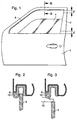
- a door 1 of a vehicle automobile having a frame 2 in which a window 4 slides under the action of a electric drive motor 6.
- the frame 2 of the door 1 is provided with a seal 8 in at least part of which a guide is arranged optical 10 consisting, for example, of a multimode optical fiber.
- the optical fiber 10 is associated with means for transmitting and receiving signals 12 and 14 respectively optics propagating inside said fiber 10. These means are adapted to control the operation of the window regulator mechanism or the anti-theft system of the vehicle they equip.
- the optical fiber 10 is placed in the seal 8 outside the window path 4.
- the window 4 going up under the action of its drive motor 6, if a finger 16 is wedged between said window 4 and the frame 2 of the door 1 (FIG. 3), the fiber lens 10 is crushed by finger 16.
- the optical fiber 10 deforms, which causes a local modification of its radius of curvature. This curvature causes a attenuation of the power of optical signals propagating in the fiber optical 10. This results in a drop in the amplitude of the electrical signals emitted by the receiver 14 to a central unit 18 which, in response to this drop, generates a signal to stop or reverse the direction of movement of the motor 6 driving the window 4.
- a pressure sensor designated as a whole by the general reference number 20, includes your multimode optical fiber 10 mentioned above which operates on the principle of intensity modulation of the light which propagates there according to the pressure applied.
- the sensor pressure 20 is associated with the transmission 12 and reception 14 means of the optical signals propagating inside said fiber 10.
- the pressure sensor 20 operates in transmission mode.
- Optical fiber 10 includes a part 10a which constitutes the sensitive element of the pressure 20, and a part 10b serving as a light transmission line.
- the emission means 12 inject a light signal at one end of the fiber 10.
- These emission means 12 comprise an optical source which is packaged so as to be fixedly attached to the optical fiber 10, this in order to avoid the use of too expensive optical connectors.
- Source optical will preferably be a light emitting diode.
- the light signal injected into the optical fiber 10 propagates to the detector 14 such that a photodiode also securely attached to the other end of said fiber 10.
- the light emitting diode and the photodiode are SMD (Surface Mount) Device), crimped in the same case also receiving the two ends of the optical fiber 10 forming the pressure sensor 20.
- the housing comprises on the other hand, connection means facilitating its mounting on a card electronic.
- the pressure sensor 20 can also operate in reflection mode.
- the source 12 and the receiver 14 are located at the same end of the fiber 10, while a reflector 11 reflecting the signals luminous is arranged at the other end of said fiber 10.
- the functions transmission and reception are preferably ensured by a diode laser with its own photodetector cell.
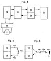
- a supply circuit 22 supplies the optical source 12 with current.
- This current can be continuous and / or variable periodically over time. According to a preferred characteristic of the invention, the current will be continuous during the periods of operation of the drive motor 6, and periodic rectangular shape during downtime.
- Circuit 22 also includes circuits for converting and amplifying currents from the detector 14.
- the safety device also comprises a circuit 24 of the drive motor 6.
- This control circuit 24 has a bridge type structure for bidirectional control of said motor 6. It can be made entirely from semiconductors or include Relays.
- MOS type transistors makes it possible to switch the relay with very low current, which improves the service life of components.
- Another advantage is that the same component MOS can be used as a current measurement element to limit this last, to detect the limit switches and protect the motor 6 against current peaks.
- This central unit 18 comprises a microcontroller and / or a microprocessor which manages the control, measurement and calibration of the pressure sensor 20 by means of programs and of computer algorithms implanted in a non-volatile memory accessible to said microcontroller.
- the central unit 18 has for this purpose means of analog-digital conversion. Control by the central unit 18 stop and run states as well as the direction of rotation of the motor drive 6 takes place via the control circuit 24. This last measurement and also transmits to the central unit 18 the variations of the supply current to motor 6 in order to detect the end positions of window stroke 4 and protect the electronics against current spikes resulting therefrom, as will be described in more detail later.
- the method is measures the frequency of the pulses caused by the switching of brushes such as 28 of the electric motor 6 driving the window 4, and we stop the drive of said window 4 when the frequency of the pulses is lower than a predetermined threshold frequency.
- these detection means comprise a MOS transistor 30 at the terminals of which the pulses caused by the switching of the brushes 28.
- the MOS transistor 30 further controls the switching of relays such as 32 of the motor electric 6, and therefore determines the direction of movement of the movable panel 4.
- the pulses collected at the terminals of the MOS transistor 30 then pass to through a filter 34, an amplifier 36, then are reshaped by means of a comparator 38. Finally, the pulses are sent to comparison means for comparing the frequency of the pulses at a threshold frequency. These means are constituted by the central unit 18 which calculates the pulse frequency and compares it to the stored threshold frequency in memory. Finally, when the pulse frequency becomes lower at the threshold frequency, the central unit 18 produces a second alarm signal which causes it to stop or reverse the running direction of the engine 6. It thus becomes possible to detect the limit switch or the presence of a foreign body such as, for example, an arm braking the movement of the window 4 and opposing its raising. The comparison of the frequency measured with a reference frequency therefore makes it possible to perform a predetection of obstacle and to avoid, in certain cases, the pinching. She also protects the drive motor 6 and its circuit control 24 against particularly harmful current peaks.
- the central unit 18 measures the frequency of the pulses caused by the switching of the brushes 28 of the drive motor 6 and deduces therefrom the speed of rotation of the rotor of said motor 6. Knowing the speed of rotation of the motor 6, the central unit 18 can calculate the stroke of the window 4 from a previously known reference position stored in memory. This reference position corresponds to the last calculated position of the window 4 before stopping the drive motor 6.
- the method of indirect determination of the position of the glass 4 described above however has a drawback. Indeed, when the glass 4 arrives in its end position and that its drive motor 6 stops, it is not possible to determine whether this stop is due to the the window 4 is in abutment against the frame 2 of the door 1 in which it slide, or if the stop is due to the presence of a foreign body trapped between the window 4 and the amount of said frame 2. This is why it is proposed to associate to the indirect type detection means direct detection means of the presence of a foreign body, these means comprising the pressure 20 to optical fiber 10 described above. So when closing the window 4, it can be deduced that in the absence of an alarm signal coming from the pressure sensor 20, the window 4 has reached the end stop race against the upright of frame 2, and that any risk of accident is avoided. Conversely, if the pressure sensor 20 produces an alarm signal, the unit control unit 18 immediately controls the reversal of the direction of travel of the drive motor 6.
- the present invention also aims to provide a sensor for pressure 20 retaining its original performance despite its sensitivity to disturbing physical quantities such as temperature and wear phenomena of the materials that constitute it.
- the central unit 18 notes the stopping of the drive motor 6, compare and correct the parameters of operation of the pressure sensor 20, taken under conditions of any environment, according to the same parameters of a standard sensor taken under known reference conditions stored in a non-volatile memory accessible to the microcontroller of said central unit 18.
- the operating parameters of the pressure 20 are measured and corrected repeatedly throughout the duration of the shutdown period of the drive motor 6. When refitting running of the drive motor 6, only the last corrections of the operating parameters of sensor 20 will be taken into account.
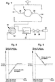
- the sensor detection circuit 20 is generally composed of a photodetector 14 followed by a circuit amplifier comprising an operational amplifier. Now everything photodetector presents a so-called dark current depending on its technology, its bias current and temperature. This current which fluctuates over time is amplified and contributes in part to the generation a parasitic offset voltage at the output. In addition, any amplifier operational presents a non-zero voltage and current offset signal, with more or less significant drift depending on the quality of the component and the temperature conditions.
- the transmitter 12 is supplied by means of a periodic rectangular current obtained by superimposing on a constant current I O a small periodic variation ⁇ I O , so that the variation of the optical signal which results can be considered linear.
- the transmitter 12 is supplied by means of a periodic rectangular current obtained by superimposing on a direct current I O a small periodic variation ⁇ I O.
- This third calibration procedure requires a first calibration of the pressure sensor 20 which makes it possible to calculate the pressure applied as a function of the voltage measured by means of an approximation polynomial of degree 3 or 4. This method allows to perform simple corrections of the coefficients of the polynomial, or more corrections developed using specific algorithms.
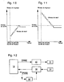
- the self-calibration method can use the variable bias current and threshold correction constant trigger illustrated in Figures 8 and 9.
- the threshold voltage of comparator 38 can here be fixed either by a circuit external to the microcontroller of the central unit 18, either by the microcontroller itself (by programming).
- the calibration method can use correction with variable trigger threshold and bias current fixed which is illustrated by Figures 10 and 11.
- the current polarization of the transmitter 12 is constant, and one increases or decreases, by example by step, the value of the threshold signal of comparator 38 which fixes the alarm threshold, until this value becomes substantially equal to the value of the output signal from the pressure sensor 20 (at the resolution near the system). Then the threshold is set to a known value lower than the signal exit.
- the microcontroller of the unit control unit 18 controls an external circuit to adjust the threshold level of alarm triggered.
- the advantage in this case is that it is not necessary to measure the output signal from the pressure sensor 20 (and therefore to equip the microcontroller with an analog / digital converter), which allows you to choose microcontroller components at low cost. But it is note that the threshold can also be set by programming. In this case, it an analog / digital converter is necessary to be able to communicate with the microcontroller. It should also be noted that all the self-calibration procedures that have been described in this patent can be combined with each other.
- the microcontroller of the central unit 18 not provided with an analog / digital converter, generates a rectangular PWM signal of fixed frequency, but with variable pulse durations. This is called pulse duration modulation or PWM (Pulse Width Modulation). Each duration value can be coded in four or eight bits or more by the microprocessor.
- the PWM signal is sent to an integrator 40 of the low-pass filter type which transforms the pulses into distinct voltage levels. It is thus possible, by varying the coding of the PWM signal, to program the form and the level of the bias current of the transmitter 12. It is also possible, if necessary, to modify by means of an integrator 42 the value of the signal comparator 38 which sets the alarm threshold.
- PFM Pulse Frequency Modulation
- coded pulse modulation Pulse Code Modulation
- the self-calibration procedure can be extended to the means of indirect system detection. Indeed, it has not been established that the indirect detection is always reliable over time. You have to expect that the performance of the drive motor 6 and the elements of transmission evolve over time. It is the same with friction of the window 4 against the gasket 8 which can evolve under the effect of deformations of frame 2 of door 1. Likewise, it is to be expected that that the movement of the glass changes according to the speed of movement of the vehicle. Failure to take these disturbance parameters into account could lead to a system malfunction. Monitoring and evaluation in the time of the stage speed of the window 4 in the area where the movement of this is substantially uniform, for example by the method of averages slippery, could correct the calculation of the position of the glass 4, as well as the value of the threshold frequency for the detection of obstacles.
- the present invention also aims to provide a sensor for fiber optic pressure simple and inexpensive to manufacture.
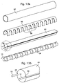
- the pressure sensor according to the invention includes a central core made of foam or rubber flexible which is in the form of a substantially cylindrical support 44 or elongated in polygonal section.
- a central core made of foam or rubber flexible which is in the form of a substantially cylindrical support 44 or elongated in polygonal section.
- two grooves such as 46 diametrically opposite which extend parallel to the longitudinal axis of said support 44 and in which the optical fiber 10 is housed without constraint (see Figure 13b which is a detailed view of the region of FIG. 13a surrounded by a line mixed).
- the cylindrical support 44 and its optical fiber 10 are inserted into a envelope 48 split longitudinally and made, for example, in a thin and hard plastic material from which a plurality have been cut clamping jaws such as 50. These jaws 50 are used for bending the optical fiber 10 by elastic pressure and to locally modify its radius curvature.
- the pressure sensor thus formed is finally wrapped in a sheath 52 made of a foam or a very flexible material.
- the central core of the pressure sensor according to the invention can be produced in the form of a support 54 formed of a periodic succession of frustoconical elements along from which the optical fiber 10 is fixed. This form of execution has the merit improve the sensitivity of the sensor by creating initial micro-bends.
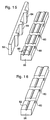
- the fiber optic 10 is mounted directly on the inner face of the jaws 50 of the casing 48.
- the free end of said jaws 50 is slightly bent to hold and guide the optical fiber 10 along envelope 48.
- This embodiment has the advantage of maintaining the 10 straight fiber optic. It has been found that the more the optical fiber used in such sensors is curved, the shorter the service life of said sensors.
- the optical fiber 10 is sandwiched between a first and a second bands 56 and 58 respectively made from two materials elastomers of the same type but of different hardnesses.
- the first strip 56 made from a relatively hard material, has a succession of transverse cavities such as 60 regularly distributed on along said strip 56.
- the upper face of the strip 56 has two grooves such that 62 in which the optical fiber 10 is housed. These grooves 62 are arranged parallel to and on either side of the axis of symmetry longitudinal of the strip 56 and have a V or semi-circular profile.
- the cavities 60 of the first strip 56 are partially or totally filled by studs such as 64 having a shape complementary to that of said cavities 60 and arranged on the underside of the second strip 58.
- the elastomeric material used to make the second strip 58 is same type as that used for the first band 56, but has a significantly lower hardness. So the first and second bands 56 and 58 are complementary both by the geometric shape and by the alternation in hardness of the materials.
- the optical fiber 10 is housed between the two bands 56 and 58 and can keep a straight profile or be slightly and periodically curved. In the case of operation in reflection mode, only one groove 62 is necessary (FIG. 16).
- the second strip 58 may be flat, produced by means of a certain thickness of a substantially soft elastomeric material.
- the spacing of the jaws 50 or the cavities 60 defines the period of microbending.
- the micro-curvature period will be chosen so as to obtain a strong coupling between the modes guided in the core of the optical fiber 10, and the modes radiated by the sheath.
- T is the modulus of the wave vector
- ⁇ and n c are the radius and the refractive index of the core of the fiber 10, respectively
- ⁇ is the relative difference between the core and cladding indices of the optical fiber 10.
- the optimal micro-curvature period must be a multiple of the period T given by the relation: T ⁇ ⁇ 2 ⁇ where p and ⁇ are respectively the core radius of the fiber 10 and the relative difference between the core and cladding indices of the optical fiber 10.
- Pressure sensitivity being greater in the case of fibers with index gradient, it is this type of fiber which will be chosen preferably.
- the optical fiber 10 can be of the plastic type, entirely made of polymer materials.
Landscapes
- Physics & Mathematics (AREA)
- General Physics & Mathematics (AREA)
- Power-Operated Mechanisms For Wings (AREA)
Abstract
Description
La présente invention concerne un procédé de commande dit mixte d'un panneau mobile entraíné à coulissement par un moteur électrique, procédé dans lequel on exploite simultanément le signal provenant d'un capteur de pression à fibre optique pour arrêter et inverser le sens de marche du moteur d'entraínement en cas de variation dudit signal, et la mesure fréquentielle des impulsions provoquées par la commutation des balais du moteur d'entraínement pour effectuer une prédétection d'obstacle et pour déterminer les positions de fin de course du panneau mobile.The present invention relates to a so-called mixed control method of a movable panel slidably driven by an electric motor, method in which the signal from a sensor is simultaneously exploited fiber optic pressure to stop and reverse the direction of the motor drive in case of variation of said signal, and the frequency measurement of pulses caused by the switching of the motor brushes training to perform an obstacle detection and to determine the end positions of the movable panel.
L'invention a aussi pour objet un dispositif de sécurité pour un tel panneau mobile comprenant des moyens de détection de la présence d'un corps étranger freinant le mouvement dudit panneau mobile et s'opposant à sa fermeture complète.The invention also relates to a safety device for such a mobile panel comprising means for detecting the presence of a foreign body slowing down the movement of said movable panel and opposing its complete closure.
L'invention a encore pour objet un capteur d'effort à fibre optique utilisable notamment dans les dispositifs de sécurité du genre susmentionné.Another subject of the invention is a fiber optic force sensor usable in particular in safety devices of the aforementioned type.
L'invention a enfin pour but de procurer un procédé de calibration du capteur d'effort susmentionné permettant d'accroítre la fiabilité du fonctionnement de ce capteur.The invention finally aims to provide a method for calibrating the aforementioned force sensor allowing to increase the reliability of the operation of this sensor.
De plus en plus de véhicules automobiles sont équipés de lève-vitres électriques, c'est-à-dire de systèmes dans lesquels les vitres sont entraínées à coulissement dans le sens de l'ouverture ou dans le sens de la fermeture par un moteur électrique dont le fonctionnement est commandé par le conducteur du véhicule au moyen d'un interrupteur manuel. De tels systèmes ont permis de réaliser des progrès sensibles en matière de sécurité automobile, dans la mesure où le conducteur peut facilement ouvrir ou fermer les vitres tout en restant attentif aux conditions de circulation et à la conduite de son véhicule. Ces systèmes présentent toutefois d'importants problèmes de fiabilité qui sont souvent liés à l'apparition de pics de courant tors d'un arrêt trop brutal du moteur d'entraínement de la vitre. On sait, en effet, que tout obstacle à l'avancement de la vitre produit, au niveau du moteur, des pics de courant qui sont généralement néfastes, surtout pour certains composants tels que les relais de commande ou les transistors de commutation. De tels pics peuvent apparaítre, par exemple lorsque l'automobiliste continue d'actionner l'interrupteur qui commande le fonctionnement du moteur d'entraínement alors que la vitre est déjà arrivée dans sa position de fermeture dans laquelle elle est appliquée contre le cadre de la porte. Des pics de courant peuvent aussi apparaítre lorsqu'un corps étranger, par exemple un bras, est en appui sur le rebord de la vitre et s'oppose à la remontée de celle-ci.More and more motor vehicles are equipped with window regulators electric, that is to say systems in which the windows are driven to sliding in the opening direction or in the closing direction by an electric motor whose operation is controlled by the driver of the vehicle by means of a manual switch. Such systems have enabled to make significant progress in terms of automotive safety, in the because the driver can easily open or close the windows while remaining attentive to traffic conditions and to driving his vehicle. However, these systems present significant reliability problems which are often linked to the appearance of twisted current peaks from an abrupt stop of the window drive motor. We know, in fact, that any obstacle to the advancement of the window produces, at the level of the motor, peaks of current which are generally harmful, especially for certain components such as control relays or switching transistors. Such peaks can appear, for example when the motorist continues to operate the switch that controls the operation of the drive motor when the window has already arrived in its closed position in which it is applied against the door frame. Current peaks can also appear when a foreign body, for example an arm, is in support on the edge of the glass and opposes the rise of the latter.
Pour remédier aux difficultés susmentionnées, une solution connue consiste à mesurer le niveau maximum du courant d'alimentation fourni au moteur d'entraínement, et à bloquer ce courant au-dessus d'un seuil prédéterminé. Cette mesure est généralement effectuée aux bornes d'un transistor de commutation dont la résistance varie d'un composant à l'autre et reste dépendante de la température. D'autres méthodes utilisent des résistances de précision (mesure de courants) ou des sondes à effet Hall (mesure de champs magnétiques), mais le prix de revient de tels composants est élevé.To remedy the above-mentioned difficulties, a known solution consists in measuring the maximum level of the supply current supplied to the drive motor, and to block this current above a threshold predetermined. This measurement is generally carried out at the terminals of a switching transistor whose resistance varies from one component to another and remains dependent on the temperature. Other methods use precision resistors (current measurement) or Hall effect probes (measurement of magnetic fields), but the cost price of such components is high.
Une autre méthode de commande, moins coûteuse et plus efficace, consiste à détecter les impulsions provoquées par la commutation des balais du moteur d'entraínement. Ces impulsions se superposent au courant continu de consommation du moteur, et leur fréquence est proportionnelle à la vitesse du rotor. Une telle technique est décrite dans le brevet américain No 4,870,333 au nom de la société Sidosha Denki Kogyo qui propose un procédé de commande d'un lève-vitres électrique pour véhicule automobile dans lequel le nombre des impulsions générées par le fonctionnement du moteur électrique entraínant la vitre est enregistré dans un compteur. Lorsque le nombre d'impulsions enregistré dans le compteur atteint une valeur maximum prédéterminée, le dispositif de commande qui exploite le système conclut que la vitre est arrivée en position de pleine ouverture et provoque l'arrêt du moteur d'entraínement. Inversement, lorsque la vitre remonte, le nombre d'impulsions enregistré dans le compteur est diminué d'une unité pour chaque tour du moteur d'entraínement. Lorsque ce nombre devient égal à zéro, le système conclut que la vitre est arrivée dans sa position de fermeture dans laquelle elle est appliquée contre le cadre de la porte, et arrête à nouveau le moteur d'entraínement.Another order method, less expensive and more efficient, consists in detecting the pulses caused by the switching of the brushes of the drive motor. These pulses are superimposed on the direct current consumption, and their frequency is proportional to the rotor speed. Such a technique is described in the American patent No 4,870,333 on behalf of the company Sidosha Denki Kogyo which offers a method of controlling an electric window regulator for a motor vehicle in which the number of pulses generated by the operation of the electric motor driving the window is recorded in a counter. When the number of pulses recorded in the counter reaches a value predetermined maximum, the control device that operates the system concludes that the window has reached the fully open position and causes stopping the drive motor. Conversely, when the window goes up, the number of pulses recorded in the counter is decreased by one for each revolution of the drive motor. When this number becomes equal to zero, the system concludes that the window has reached its position of closure in which it is applied against the door frame, and again stops the drive motor.
Le système ci-dessus a pour principal inconvénient que la vitesse d'ascension de la vitre n'est pas constante et dépend de nombreux paramètres tels que le couple d'entraínement du moteur, les frottements entre la vitre et le cadre de la porte, la vitesse et la trajectoire du véhicule etc. La position de la vitre ne peut, par conséquent, être calculée avec une précision suffisante pour pouvoir déterminer de manière exacte le moment où la fenêtre est complètement fermée. Avec une telle méthode, on peut tout au plus déterminer une zone de fin de course dans laquelle on sait que la vitre est au voisinage du cadre de la porte. Le moteur d'entraínement peut, par conséquent, être arrêté sur ordre du dispositif de commande avant que la fenêtre ne soit complètement fermée. Inversement, le moteur peut continuer à être alimenté en courant alors que la fenêtre est déjà complètement fermée, ce qui produit des pics de courant nefastes pour le moteur et l'électronique de commande. D'autre part, rien dans le brevet Sidosha n'est prévu pour détecter avant pincement une surcharge qui ferait obstacle à l'avancement de la vitre. Enfin, rien n'est prévu pour détecter la présence d'un corps étranger tel qu'une main d'enfant dont l'épaisseur est égale ou inférieure à la hauteur de la zone de fin de course. Or, lors de la fermeture automatique de panneaux mobiles tels que, notamment une vitre d'un véhicule automobile, on doit chercher à garantir la sécurité en évitant le coincement d'un corps étranger tel que, par exemple, un bras ou une main, entre ladite vitre et le cadre de la porte contre lequel celle-ci doit être appliquée. A cet effet, en cas de coincement, un dispositif de sécurité arrête l'entraínement ou inverse le sens du mouvement de la glace. Parmi les dispositifs de sécurité connus, une solution consiste à incorporer un guide d'ondes électromagnétiques, par exemple une fibre optique, à l'intérieur du joint d'étanchéité dans lequel est guidé la vitre. Un émetteur, par exemple une diode laser, injecte un signal lumineux à une extrémité de la fibre. Ce signal se propage jusqu'à un récepteur, par exemple une photodiode, placée à l'autre extrémité de la fibre. En cas d'incident, le corps étranger est entraíné par la glace remontant vers le joint d'étanchéité et exerce une pression sur la fibre optique. Sous l'effet de la pression, la fibre optique se déforme, ce qui entraíne une modification locale de son rayon de courbure. Cette modification du rayon de courbure de la fibre provoque des pertes importantes, et par suite une baisse de l'amplitude du signal optique capté par le récepteur. Il en résulte une baisse de l'amplitude du signal électrique émis par le récepteur vers un circuit de commande qui, en réponse à cette baisse, élabore un signal d'arrêt ou d'inversion du sens de marche du moteur entraínant la glace.The main disadvantage of the above system is that speed window ascension is not constant and depends on many parameters such as engine drive torque, friction between the glass and the door frame, the speed and trajectory of the vehicle etc. The position of the glass cannot therefore be calculated with a sufficient precision to be able to accurately determine when the window is completely closed. With such a method, we can at most no longer determine an end of travel zone in which we know that the window is near the door frame. The drive motor can, by Therefore, be stopped on command of the control device before the window is not completely closed. Conversely, the engine can continue to be supplied with current when the window is already completely closed, which produces harmful current peaks for the motor and electronics control. On the other hand, nothing in the Sidosha patent is provided for detect an overload before pinching which would prevent advancement of the glass. Finally, nothing is planned to detect the presence of a body stranger such as a child's hand whose thickness is equal to or less than the height of the limit switch area. However, during the automatic closing of movable panels such as, in particular a window of a motor vehicle, must seek to guarantee safety by avoiding the entrapment of a body stranger such as, for example, an arm or a hand, between said window and the door frame against which it is to be applied. To this end, in the event jamming device, a safety device stops the drive or reverses the direction of ice movement. Among the known security devices, one solution is to incorporate an electromagnetic waveguide, by example an optical fiber, inside the seal in which is guided the glass. A transmitter, for example a laser diode, injects a signal bright at one end of the fiber. This signal propagates to a receiver, for example a photodiode, placed at the other end of the fiber. In the event of an incident, the foreign body is entrained by the ice rising towards the seal and exerts pressure on the optical fiber. Under the influence of pressure, the optical fiber deforms, which causes a local modification of its radius of curvature. This change in the radius of curvature of the fiber causes significant losses, and consequently a decrease in amplitude of the optical signal received by the receiver. This results in a decrease of the amplitude of the electrical signal emitted by the receiver to a circuit command which, in response to this drop, generates a stop signal or reversing the direction of the motor driving the window.
Les dispositifs de sécurité du genre susdécrit qui utilisent des capteurs de pression à fibre optique comme détecteurs d'obstacles présentent de nombreux inconvénients tant au niveau de leur fabrication industrielle qu'au niveau de leur fonctionnement chez l'utilisateur. Ces dispositifs de sécurité doivent, en effet, être produits à grande échelle pour satisfaire les besoins de marchés tels que celui de l'automobile. Ceci suppose donc un processus de fabrication à la fois simple et rapide avec des composants et des matériaux peu coûteux. Il en va de même pour les procédures de test et de calibration qui doivent être rapides et permettre au capteur de conserver ses caractéristiques de fonctionnement dans le temps. Comme on va le voir dans la description qui suit, il est difficile, dans de telles conditions, d'obtenir des produits ayant des caractéristiques homogènes.Safety devices of the kind described above which use sensors fiber optic pressure sensors as obstacle detectors have many drawbacks both in terms of their industrial production and level of their functioning at the user. These safety devices indeed, must be produced on a large scale to meet the needs of markets such as the automotive market. This therefore presupposes a process of simple and fast manufacturing with components and materials cheap. The same goes for test and calibration procedures which must be fast and allow the sensor to keep its operating characteristics over time. As we will see in the description which follows, it is difficult, under such conditions, to obtain products with homogeneous characteristics.
Un premier problème est lié au fait qu'il est difficile de pouvoir disposer de quantités importantes et à bas coût de sources optiques présentant des caractéristiques peu dispersées. Ceci concerne notamment la puissance et l'angle d'émission ainsi que le spectre de rayonnement de ces sources.A first problem is related to the fact that it is difficult to be able to have large quantities and at low cost of optical sources having little dispersed characteristics. This concerns in particular the power and the emission angle as well as the radiation spectrum of these sources.
Un second problème est lié au fait que la fibre optique utilisée dans le capteur doit être fixée à la source optique soit au moyen de connecteurs spécifiques, soit plus simplement par collage. Ceci nécessite plusieurs opérations de conditionnement de l'extrémité de la fibre (dénudage du revêtement, fracture ou polissage), de centrage de la fibre par rapport à la source optique, et enfin de fixation au moyen de résines à durcissement rapide. Une production à grande échelle implique forcément une dispersion importante des rendements à l'injection de puissance dans la fibre, ce qui affecte les performances du capteur.A second problem is related to the fact that the optical fiber used in the sensor must be fixed to the optical source either by means of connectors specific, or more simply by gluing. This requires several conditioning operations at the end of the fiber (stripping the coating, fracture or polishing), centering the fiber in relation to the optical source, and finally fixing by means of hardening resins fast. Large-scale production necessarily involves dispersal significant efficiency in the injection of power into the fiber, which affects the performance of the sensor.
Comme décrit ci-dessus, les capteurs à fibre optique fonctionnent dans leur majorité sur le principe des pertes induites par la variation du rayon de courbure de ladite fibre sous l'effet d'une pression. La mise en place de la fibre et le conditionnement de la partie sensible du capteur introduisent donc nécessairement une dispersion des contraintes dans la fibre optique, ce qui entraíne une dispersion des performances des capteurs.As described above, fiber optic sensors operate in their majority on the principle of losses induced by the variation of the radius of curvature of said fiber under the effect of pressure. The establishment of the fiber and conditioning of the sensitive part of the sensor therefore introduce necessarily a dispersion of the stresses in the optical fiber, which results in scattered sensor performance.
On peut également noter que les performances des capteurs dépendent fortement des conditions dans lesquelles ils sont utilisés, et de leur environnement. C'est le cas, par exemple, des applications automobiles où les capteurs doivent fonctionner dans des plages de température ambiante comprises entre -40°C et +85°C. Il est clair que, dans de telles conditions, les caractéristiques de certains composants comme la source optique ne peuvent rester constantes (puissance d'émission et domaine spectral). Il en est de même pour le rendement à l'injection de puissance dans la fibre qui dépend fortement des propriétés thermiques des matériaux utilisés pour la connexion source-fibre. It can also be noted that the performance of the sensors strongly depend on the conditions under which they are used, and on their environment. This is the case, for example, in automotive applications where the sensors must operate within ambient temperature ranges between -40 ° C and + 85 ° C. It is clear that, under such conditions, the characteristics of certain components such as the optical source can remain constant (transmission power and spectral range). It the same is true for the power injection efficiency in the fiber which strongly depends on the thermal properties of the materials used for the source-fiber connection.
Le problème est encore plus important au niveau de la partie sensible du capteur. En effet, en supposant que la fibre optique ne soit pas elle-même sensible aux variations de température, les matériaux qui servent de support et de gaine, en général des polymères, peuvent subir des contraintes thermiques, ce qui revient à appliquer des variations de pression sur la fibre. Ces effets, auxquels s'ajoute la sensibilité intrinsèque de la fibre optique à la température, peuvent entraíner des variations de plus de 80% du signal de sortie.The problem is even more important at the sensitive part of the sensor. Indeed, assuming that the optical fiber is not itself sensitive to temperature variations, the materials that serve as support and sheath, in general polymers, can be stressed thermal, which amounts to applying pressure variations on the fiber. These effects, to which is added the intrinsic sensitivity of optical fiber to temperature, can cause variations of more than 80% of the signal exit.
Enfin, aux problèmes liés aux conditions d'utilisation du capteur, s'ajoutent les variations inévitables des caractéristiques de celui-ci provoquées par l'usure normale des matériaux et des composants.Finally, to the problems related to the conditions of use of the sensor, there are the inevitable variations in its characteristics caused by normal wear and tear of materials and components.
L'énumération des problèmes susmentionnés montre les difficultés qu'il s'agit de surmonter pour pouvoir fabriquer en grandes séries et à moindres coûts des capteurs de pression à fibre optique utilisables comme détecteurs d'obstacles. La sensibilité à certaines grandeurs perturbatrices ainsi que les phénomènes d'usure ne permettent pas de conserver la calibration d'origine. Il en résulte des problèmes de fiabilité voire, dans certains cas, de non fonctionnement des dispositifs de sécurité utilisant de tels capteurs.The list of the above-mentioned problems shows the difficulties it to overcome in order to be able to manufacture in large series and at lower costs of fiber optic pressure sensors usable as detectors obstacles. Sensitivity to certain disturbing quantities as well as wear phenomena do not allow to keep the original calibration. he this results in reliability problems or, in some cases, failure to operation of safety devices using such sensors.
La présente invention a pour but de remédier aux problèmes et inconvénients susmentionnés en offrant un dispositif de sécurité fiable pour l'entraínement et la fermeture de panneaux d'obturation coulissant électriquement.The object of the present invention is to remedy the problems and disadvantages mentioned above by providing a reliable safety device for driving and closing sliding shutter panels electrically.
A cet effet, l'invention concerne un procédé de commande mixte d'un panneau mobile entraíné à coulissement par un moteur électrique, comportant les étapes consistant à :
- détecter la présence ou l'absence d'un corps étranger susceptible de s'opposer à la fermeture complète dudit panneau mobile;
- produire un signal d'alarme lorsque ladite présence est détectée;
- mesurer la fréquence des impulsions provoquées par la rotation du moteur électrique entraínant le panneau mobile, et
- arrêter le moteur d'entraínement lorsque la fréquence des impulsions devient sensiblement nulle en l'absence dudit signal d'alarme, ou
- inverser le sens de marche du moteur d'entraínement lorsque la fréquence des impulsions diminue ou devient sensiblement nulle et qu'il y a présence dudit signal d'alarme.
- detect the presence or absence of a foreign body capable of opposing the complete closure of said movable panel;
- produce an alarm signal when said presence is detected;
- measure the frequency of the pulses caused by the rotation of the electric motor driving the movable panel, and
- stop the drive motor when the pulse frequency becomes substantially zero in the absence of said alarm signal, or
- reverse the direction of operation of the drive motor when the pulse frequency decreases or becomes substantially zero and there is presence of said alarm signal.
Ainsi, lors de la fermeture de la vitre, on peut déduire qu'en l'absence de signal d'alarme, la vitre est arrivée en butée contre le cadre de la porte et que tout risque d'accident est évité. Inversement, dans le cas de la présence d'un signal d'alarme, on commande immédiatement l'inversion du sens de marche du moteur d'entraínement. Grâce à ces caractéristiques, le procédé de détection mixte selon l'invention permet simultanément d'accroítre la sécurité des personnes et de protéger efficacement les parties électriques et électroniques contre les surcourants.Thus, when the window is closed, it can be deduced that in the absence alarm signal, the window has come into abutment against the door frame and that any risk of accident is avoided. Conversely, in the case of the presence of an alarm signal, the direction of running the drive motor. Thanks to these characteristics, the process of mixed detection according to the invention simultaneously makes it possible to increase the personal safety and effectively protect the electrical parts and electronic against overcurrents.
Selon une autre caractéristique du procédé de l'invention, on mesure la fréquence des impulsions provoquées par la rotation du moteur électrique entraínant le panneau mobile, et on arrête ou on inverse le sens de marche dudit moteur lorsque la fréquence de ces impulsions devient inférieure à une fréquence seuil prédéterminée.According to another characteristic of the process of the invention, the frequency of pulses caused by rotation of the electric motor driving the movable panel, and we stop or reverse the direction of travel said motor when the frequency of these pulses becomes less than one predetermined threshold frequency.
Selon encore une autre caractéristique du procédé, on détecte la présence ou l'absence d'un corps étranger susceptible de s'opposer à la fermeture complète du panneau mobile à l'aide d'un capteur de pression à fibre optique.According to yet another characteristic of the process, the presence or absence of a foreign body likely to oppose the complete closure of the movable panel using a pressure sensor optical fiber.
Selon encore une autre caractéristique du procédé de l'invention, on déduit de la mesure de fréquence des impulsions provoquées par la rotation du moteur électrique d'entraínement une indication de la course du panneau mobile à partir d'une position de référence connue préalablement, et on commande une rampe de décélération de la vitesse du moteur d'entraínement lorsque le panneau mobile arrive dans une zone de fin de course.According to yet another characteristic of the process of the invention, it is deduced from the frequency measurement of the pulses caused by the rotation of the electric drive motor an indication of the travel of the panel mobile from a previously known reference position, and controls a deceleration ramp of the speed of the drive motor when the movable panel arrives in an end of travel zone.
Selon encore une autre caractéristique du procédé, la position de référence est la dernière position calculée du panneau mobile avant l'arrêt du moteur d'entraínement.According to yet another characteristic of the process, the position of reference is the last calculated position of the movable panel before stopping the drive motor.
La mesure de la vitesse de rotation du moteur d'entraínement permet de calculer la course du panneau mobile à partir d'une position de référence préalablement connue. Dans le cas d'un véhicule automobile, du fait des forces d'inertie dues aux secousses, aux effets de friction et aux glissements, la détermination indirecte de la position de la vitre présente un certain taux d'erreur. Ce taux d'erreur est cumulatif. Ainsi, après dix essais de descente et de remontée de la vitre, l'écart cumulé entre la position calculée et la position réelle de ladite vitre est de l'ordre de un à deux centimètres. Celle erreur reste cependant suffisamment faible pour permettre de définir une zone de fin de course pour les mouvements de descente et de montée de la vitre, zone dans laquelle ladite vitre se trouve au voisinage du cadre de la porte contre lequel elle doit être appliquée. Le temps de retard mis par la variation du courant par rapport à la vitesse de rotation du moteur est mis à profit pour limiter les surcourants et pour protéger efficacement le moteur et son unité de commande.The measurement of the rotation speed of the drive motor allows calculate the travel of the movable panel from a reference position previously known. In the case of a motor vehicle, due to the forces inertia due to shaking, friction and sliding, the indirect determination of the position of the window has a certain rate error. This error rate is cumulative. So after ten descent attempts and window lift, the cumulative difference between the calculated position and the position actual size of said window is of the order of one to two centimeters. That error remains low enough to define an end zone for lowering and raising movements of the window, zone wherein said window is in the vicinity of the door frame against which it should be applied. The delay time taken by the variation of the current with respect to the rotational speed of the motor is taken advantage of for limit overcurrents and to effectively protect the motor and its unit control.
L'invention concerne également un procédé de commande d'un panneau mobile entraíné à coulissement par un moteur électrique, caractérisé en ce qu'il consiste à mesurer la fréquence des impulsions provoquées par la commutation des balais du moteur électrique entraínant le panneau mobile, et à arrêter ou à inverser le sens de marche dudit moteur lorsque la fréquence de ces impulsions devient inférieure à une fréquence seuil prédéterminée.The invention also relates to a method for controlling a panel. mobile driven by sliding by an electric motor, characterized in that it consists in measuring the frequency of the impulses caused by the switching of the brushes of the electric motor driving the movable panel, and to stop or reverse the direction of travel of said motor when the frequency of these pulses becomes less than a predetermined threshold frequency.
La fréquence des impulsions étant proportionnelle à la vitesse de rotation du rotor du moteur d'entraínement, il devient possible de détecter la présence d'un obstacle freinant le mouvement du panneau d'obturation et s'opposant à sa remontée. C'est le cas, par exemple, de l'action d'un bras posé sur le rebord d'une vitre d'un véhicule automobile. La comparaison de la vitesse mesurée avec une vitesse de référence permet donc d'effectuer une prédétection d'obstacle et d'éviter, dans certains cas, le pincement. Elle permet également de diminuer de manière notable les pics de courant qui sont particulièrement néfastes, notamment pour l'électronique de commande du moteur d'entraínement.The frequency of the pulses being proportional to the speed of rotation of the rotor of the drive motor, it becomes possible to detect the presence of an obstacle slowing down the movement of the cover panel and opposing its rise. This is the case, for example, of the action of an arm placed on the edge of a window of a motor vehicle. The comparison of the speed measured with a reference speed therefore makes it possible to perform a obstacle detection and in certain cases to avoid pinching. She also significantly reduces the current peaks which are particularly harmful, especially for control electronics of the drive motor.
L'invention concerne également un dispositif de sécurité comprenant des moyens de détection de la présence d'un corps étranger freinant le mouvement d'un panneau mobile entraíné à coulissement par un moteur électrique et s'opposant à sa fermeture, caractérisé en ce que lesdits moyens de détection sont du type indirect, basés sur la mesure de la fréquence des impulsions provoquées par la commutation des balais du moteur électrique.The invention also relates to a security device comprising means for detecting the presence of a foreign body slowing the movement of a movable panel driven by sliding by a motor electric and opposing its closure, characterized in that said means are of the indirect type, based on the measurement of the frequency of pulses caused by the switching of the brushes of the electric motor.
Selon une autre caractéristique de l'invention, il est proposé d'associer aux moyens de détection du type indirect susmentionnés des seconds moyens de détection directe de la présence d'un corps étranger, ces moyens comprenant un capteur de pression constitué par une fibre optique associée à des moyens d'émission et de réception de signaux optiques se propageant à l'intérieur de ladite fibre.According to another characteristic of the invention, it is proposed to associate to the aforementioned indirect type detection means of the second means direct detection of the presence of a foreign body, these means comprising a pressure sensor constituted by an associated optical fiber to means for transmitting and receiving propagating optical signals inside said fiber.
Un autre but de la présente invention est de procurer un capteur de pression à fibre optique utilisable comme détecteur d'obstacles conservant sa calibration d'origine malgré sa sensibilité à des grandeurs physiques perturbatrices telles que la température et aux phénomènes d'usure des matériaux qui le constituent.Another object of the present invention is to provide a sensor for fiber optic pressure usable as an obstacle detector retaining its original calibration despite its sensitivity to physical quantities disturbing factors such as temperature and wear phenomena materials that make it up.
A cet effet, l'invention concerne également un procédé de calibration d'un capteur de pression à fibre optique utilisé comme détecteur d'obstacles dans un système d'entraínement d'un panneau mobile coulissant électriquement, le capteur comprenant un émetteur alimenté électriquement qui injecte un signal lumineux dans une fibre optique, le signal lumineux se propageant jusqu'à un récepteur qui émet, en réponse au signal lumineux transmis par la fibre optique, un signal électrique vers une centrale de commande à microcontrôleur et/ou à microprocesseur qui analyse l'information en provenance dudit récepteur et permet, en cas d'incident, d'arrêter ou d'inverser le sens de marche d'un moteur électrique entraínant le panneau mobile, le procédé étant caractérisé en ce que, pendant les périodes où l'on constate l'arrêt du moteur d'entraínement du panneau mobile, on compare et on corrige les paramètres de fonctionnement du capteur de pression, pris dans des conditions d'environnement quelconques, en fonction des mêmes paramètres d'un capteur étalon pris dans des conditions de référence connues stockées dans une mémoire non volatile accessible au microcontrôleur et/ou au microprocesseur de la centrale de commande.To this end, the invention also relates to a calibration method a fiber optic pressure sensor used as an obstacle detector in a sliding sliding panel drive system electrically, the sensor comprising an electrically powered transmitter which injects a light signal into an optical fiber, the light signal propagating to a transmitting receiver in response to the light signal transmitted by optical fiber, an electrical signal to a central microcontroller and / or microprocessor control which analyzes information from said receiver and allows, in the event of an incident, to stop or reverse the direction of travel of an electric motor driving the movable panel, the method being characterized in that, during the periods where we note the stopping of the motor for driving the movable panel, we compare and correct the operating parameters of the pressure, taken under any environmental conditions, depending of the same parameters of a standard sensor taken under conditions of known reference stored in a non-volatile memory accessible to the microcontroller and / or to the microprocessor of the control unit.
Grâce à ces caractéristiques, la procédure de calibration du capteur de pression débute dès l'instant où l'arrêt du moteur d'entraínement du panneau mobile est constaté. Préférentiellement, les paramètres de fonctionnement du capteur sont mesurés et corrigés de manière répétitive pendant toute la durée de la période d'arrêt dudit moteur d'entraínement. Durant les périodes de fonctionnement du moteur, seules les dernières corrections des paramètres de fonctionnement du capteur de pression stockées en mémoire seront prises en compte. Les performances du capteur de pression peuvent ainsi être conservées, malgré les phénomènes d'usure et l'existence de grandeurs physiques perturbatrices auxquelles le capteur est sensible.Thanks to these characteristics, the calibration procedure of the pressure starts as soon as the panel drive motor stops mobile is found. Preferably, the operating parameters of the sensor are measured and corrected repeatedly throughout the duration of the stopping period of said drive motor. During the periods of engine operation, only the last corrections of the pressure sensor operating parameters stored in memory will be taken into account. Pressure sensor performance can thus be preserved, despite the phenomena of wear and the existence of disturbing physical quantities to which the sensor is sensitive.
Selon une première variante de mise en oeuvre, le procédé de l'invention comprend les étapes qui consistent à :
- couper un bref instant le courant électrique d'alimentation de l'émetteur dès l'instant où l'on constate l'arrêt du moteur d'entraínement du panneau mobile;
- mesurer le niveau d'offset du signal électrique émis par le récepteur, puis ramener sa valeur à zéro;
- alimenter à nouveau l'émetteur au moyen d'un courant électrique continu constant I0, et
- mesurer le niveau de sortie VS du récepteur, et lui affecter un
coefficient k tel que
- cut the electrical power supply to the transmitter for a short time as soon as the mobile panel drive motor is stopped;
- measure the offset level of the electrical signal emitted by the receiver, then reduce its value to zero;
- supply the transmitter again with a constant direct electric current I 0 , and
- measure the output level V S of the receiver, and assign it a coefficient k such that
Selon une seconde variante de mise en oeuvre, le procédé de l'invention comprend les étapes qui consistent à :
- alimenter l'émetteur au moyen d'un courant rectangulaire périodique;
- mesurer le niveau haut de sortie VS du récepteur ainsi que sa variation ΔVS, et
- effectuer l'opération
- supply the transmitter by means of a periodic rectangular current;
- measure the high output level V S of the receiver as well as its variation ΔV S , and
- perform the operation
Selon une autre variante de mise en oeuvre, le procédé de l'invention comprend les étapes qui consistent à :
- alimenter l'émetteur au moyen d'un courant rectangulaire périodique;
- mesurer le niveau haut de sortie VS du récepteur, ainsi que sa variation ΔVS;
- calculer la pression appliquée en fonction du niveau de signal mesuré au moyen d'une équation polynomiale de degré supérieur ou égal à 1 dont les coefficients sont initialement déterminés lors d'une première calibration, et
- corriger périodiquement ces coefficients en fonction des résultats de la mesure pour obtenir une mesure fiable de la pression.
- supply the transmitter by means of a periodic rectangular current;
- measure the high output level V S of the receiver, as well as its variation ΔV S ;
- calculating the applied pressure as a function of the signal level measured by means of a polynomial equation of degree greater than or equal to 1, the coefficients of which are initially determined during a first calibration, and
- periodically correct these coefficients based on the measurement results to obtain a reliable pressure measurement.
Un autre but encore de la présente invention est de procurer un capteur de pression simple et peu coûteux à fabriquer.Yet another object of the present invention is to provide a pressure sensor simple and inexpensive to manufacture.
D'autres caractéristiques et avantages de la présente invention apparaítront plus clairement à la lecture de la description qui suit d'un exemple de mise en oeuvre du procédé selon l'invention, cet exemple étant donné à titre purement illustratif et non limitatif en liaison avec les dessins annexés sur lesquels :
- la figure 1 représente une portière d'un véhicule automobile munie du dispositif de sécurité selon l'invention;
- la figure 2 est une vue en coupe selon la ligne II-II de la figure 1;
- la figure 3 est une vue analogue à celle de la figure 2 sur laquelle on a représenté un corps étranger tel qu'un doigt coincé entre la vitre et le cadre de la porte;
- la figure 4 est une représentation schématique du dispositif de sécurité selon l'invention;
- la figure 5 est une représentation schématique d'un capteur de pression à fibre optique fonctionnant en mode transmission;
- la figure 6 est une représentation schématique d'un capteur de pression à fibre optique fonctionnant en mode réflexion;
- la figure 7 est une représentation schématique des moyens de commutation des états de marche-arrêt et de commande du sens de rotation du moteur ainsi que des moyens de détection de type indirect de la présence d'un corps étranger freinant le mouvement de la vitre du véhicule automobile;
- les figures 8 à 12 illustrent deux procédures d'autocalibration du système de sécurité selon l'invention, et
- les figures 13 à 16 sont des vues en perspective de différentes variantes d'exécution du capteur de pression selon l'invention.
- Figure 1 shows a door of a motor vehicle provided with the safety device according to the invention;
- Figure 2 is a sectional view along line II-II of Figure 1;
- Figure 3 is a view similar to that of Figure 2 in which there is shown a foreign body such as a finger wedged between the glass and the door frame;
- Figure 4 is a schematic representation of the safety device according to the invention;
- Figure 5 is a schematic representation of a fiber optic pressure sensor operating in transmission mode;
- Figure 6 is a schematic representation of a fiber optic pressure sensor operating in reflection mode;
- FIG. 7 is a schematic representation of the means for switching the on-off states and for controlling the direction of rotation of the motor as well as means for indirectly detecting the presence of a foreign body slowing down the movement of the window of the motor vehicle;
- FIGS. 8 to 12 illustrate two self-calibration procedures for the security system according to the invention, and
- Figures 13 to 16 are perspective views of different alternative embodiments of the pressure sensor according to the invention.
La présente invention procède de l'idée générale inventive qui consiste à procurer un système de détection mixte dans lequel les moyens de détection indirecte, basés sur la mesure de la fréquence des impulsions provoquées par la commutation des balais du moteur électrique d'entraínement, permettent de protéger efficacement les éléments électriques et électroniques contre les pics de courant qui leur sont particulièrement néfastes, tandis que les moyens de détection directe, basés sur la mesure de la variation d'une grandeur physique sous l'effet de la présence d'un corps étranger s'opposant à la fermeture complète d'un panneau mobile, permettent d'accroítre considérablement la sécurité des personnes.The present invention proceeds from the general inventive idea which consists in provide a mixed detection system in which the detection means indirect, based on measuring the frequency of the pulses caused by switching the brushes of the electric drive motor, allow effectively protect electrical and electronic components from current peaks which are particularly harmful to them, while the means direct detection, based on the measurement of the variation of a quantity physical under the effect of the presence of a foreign body opposing the complete closure of a movable panel, allow to increase security of people.
La présente invention va être décrite en référence à un dispositif de lève-vitres électrique équipant un véhicule automobile. Il va néanmoins de soi que la présente invention s'applique à tout type de panneau mobile coulissant électriquement tel qu'un toit ouvrant d'un véhicule automobile, les portes d'un ascenseur, des portes coupe-feu ou autre.The present invention will be described with reference to a device for electric windows fitted to a motor vehicle. It goes without saying, however that the present invention applies to any type of sliding sliding panel electrically such as a sunroof of a motor vehicle, the doors of a elevator, fire doors or whatever.
En référence aux figures 1 à 6, on voit une portière 1 d'un véhicule
automobile ayant un cadre 2 dans lequel coulisse une vitre 4 sous l'action d'un
moteur électrique d'entraínement 6. Le cadre 2 de la portière 1 est muni d'un
joint d'étanchéité 8 dans une partie au moins duquel est disposé un guide
optique 10 constitué, par exemple, par une fibre optique multimode. Comme
cela sera décrit plus en détail par la suite, la fibre optique 10 est associée à
des moyens d'émission et de réception respectivement 12 et 14 de signaux
optiques se propageant à l'intérieur de ladite fibre 10. Ces moyens sont
adaptés pour contrôler le fonctionnement du mécanisme de lève-vitres
électrique ou du système antivol du véhicule qu'ils équipent.Referring to Figures 1 to 6, we see a
Comme il ressort de la figure 2, la fibre optique 10 est placée dans la
garniture d'étanchéité 8 à l'extérieur du chemin de la vitre 4. La vitre 4
remontant sous l'action de son moteur d'entraínement 6, si un doigt 16 est
coincé entre ladite vitre 4 et le cadre 2 de la portière 1 (figure 3), la fibre
optique 10 est écrasée par le doigt 16. Sous l'effet de la pression exercée
par le doigt 16, la fibre optique 10 se déforme, ce qui entraíne une
modification locale de son rayon de courbure. Celle courbure entraíne une
atténuation de la puissance des signaux optiques se propageant dans la fibre
optique 10. Il en résulte une baisse de l'amplitude des signaux électriques émis
par le récepteur 14 vers une unité centrale 18 qui, en réponse à cette baisse,
élabore un signal d'arrêt ou d'inversion du sens de marche du moteur 6
entraínant la vitre 4.As shown in FIG. 2, the
Sur la figure 4, on voit une représentation schématique du dispositif de
sécurité selon l'invention. Un capteur de pression, désigné dans son ensemble
par la référence numérique générale 20, comprend ta fibre optique multimode
10 susmentionnée qui fonctionne sur le principe de la modulation d'intensité de
la lumière qui s'y propage en fonction de la pression appliquée. Le capteur de
pression 20 est associé aux moyens d'émission 12 et de réception 14 des
signaux optiques se propageant à l'intérieur de ladite fibre 10.In Figure 4, we see a schematic representation of the device
security according to the invention. A pressure sensor, designated as a whole
by the
Selon une première variante d'exécution représentée à la figure 5, le
capteur de pression 20 fonctionne en mode transmission. La fibre optique 10
comprend une partie 10a qui constitue l'élément sensible du capteur de
pression 20, et une partie 10b servant de ligne de transmission de la lumière.
Les moyens d'émission 12 injectent un signal lumineux à une extrémité de la
fibre 10. Ces moyens d'émission 12 comprennent une source optique qui est
conditionnée de manière à être solidairement fixée à la fibre optique 10, ceci
afin d'éviter l'utilisation de connecteurs optiques trop coûteux. La source
optique sera de préférence une diode électroluminescente. Le signal lumineux
injecté dans la fibre optique 10 se propage jusqu'au détecteur 14 tel qu'une
photodiode également solidairement fixée à l'autre extrémité de ladite fibre
10.According to a first alternative embodiment represented in FIG. 5, the
Selon une caractéristique particulièrement avantageuse de l'invention, la
diode électroluminescente et la photodiode sont du type SMD (Surface Mount
Device), serties dans un même boítier recevant également les deux extrémités
de la fibre optique 10 formant le capteur de pression 20. Le boítier comporte
d'autre part des moyens de connexion facilitant son montage sur une carte
électronique.According to a particularly advantageous characteristic of the invention, the
light emitting diode and the photodiode are SMD (Surface Mount)
Device), crimped in the same case also receiving the two ends
of the
Selon une seconde variante d'exécution représentée à la figure 6, le
capteur de pression 20 peut également fonctionner en mode réflexion. Dans
ce dernier cas, la source 12 et le récepteur 14 sont situés à une même
extrémité de la fibre 10, tandis qu'un réflecteur 11 réfléchissant les signaux
lumineux est disposé à l'autre extrémité de ladite fibre 10. Les fonctions
d'émission et de réception sont préférentiellement assurées par une diode
laser munie de sa propre cellule photodétectrice.According to a second alternative embodiment shown in Figure 6, the
Un circuit d'alimentation 22 alimente la source optique 12 en courant.
Ce courant peut être continu et/ou variable périodiquement dans le temps.
Selon une caractéristique préférentielle de l'invention, le courant sera continu
durant les périodes de fonctionnement du moteur d'entraínement 6, et de
forme rectangulaire périodique durant les périodes d'arrêt. Le circuit 22
comporte également des circuits de conversion et d'amplification des
courants issus du détecteur 14.A
Le dispositif de sécurité selon l'invention comprend également un circuit
de commande 24 du moteur d'entraínement 6. Ce circuit de commande 24 a
une structure de type pont pour le contrôle bidirectionnel dudit moteur 6. Il
peut être constitué entièrement à base de semi-conducteurs ou comporter
des relais. L'utilisation de transistors de type MOS permet de commuter les
relais avec un courant très faible, ce qui améliore la durée de vie des
composants. Un autre avantage réside dans le fait que le même composant
MOS peut être utilisé comme élément de mesure du courant afin de limiter ce
dernier, de détecter les fins de course et de protéger le moteur 6 contre les
pics de courant.The safety device according to the invention also comprises a
Le système ci-dessus est géré par l'unité centrale 18 susmentionnée.
Cette unité centrale 18 comprend un microcontrôleur et/ou un
microprocesseur qui gère les fonctions de contrôle, de mesure et de
calibration du capteur de pression 20 au moyen de programmes et
d'algorithmes informatiques implantés dans une mémoire non volatile
accessible audit microcontrôleur. L'unité centrale 18 dispose pour cela de
moyens de conversion analogique-digitale. Le contrôle par l'unité centrale 18
des états d'arrêt et de marche ainsi que du sens de rotation du moteur
d'entraínement 6 s'effectue par l'intermédiaire du circuit de commande 24. Ce
dernier mesure et transmet également à l'unité centrale 18 les variations du
courant d'alimentation du moteur 6 afin de détecter les positions de fin de
course de la vitre 4 et de protéger l'électronique contre les pics de courant
qui en résultent, comme cela sera décrit plus en détail par la suite.The above system is managed by the aforementioned
L'unité centrale 18 gère également l'état des entrées-sorties 26 en provenance ou à destination d'autres organes internes ou externes au système. On sait, en effet, que les microcontrôleurs actuels peuvent gérer un grand nombre d'entrées-sorties, ce qui permet au système d'interagir avec plusieurs centres de commande ou de contrôle. Ceci confère au système une grande souplesse d'utilisation et d'adaptation en fonction des applications recherchées. Parmi les commandes d'entrées-sorties, on peut citer :
- les commandes manuelles pour le passager principal et les autres passagers. Ces commandes peuvent être du type graduel. Elles peuvent également être à action rapide, au sens ou une simple pression commande l'ouverture ou la fermeture complète de la vitre 4;
- les commandes centralisées de fermeture de tous les panneaux. Ces commandes peuvent être manuelles, provenir de l'ordinateur central ou du système de fermeture centralisée des portes;
- une fonction d'alarme (sécurité) dans le cas de l'introduction d'un objet entre la vitre et la coulisse.
- manual controls for the main passenger and other passengers. These commands can be of the gradual type. They can also be quick acting, in the sense that a simple pressure controls the opening or complete closing of the
window 4; - centralized closing controls for all panels. These commands can be manual, coming from the central computer or from the central locking system of the doors;
- an alarm function (security) in the event of the introduction of an object between the window and the slide.
Conformément à un premier aspect du procédé selon l'invention, on
mesure la fréquence des impulsions provoquées par la commutation des
balais tels que 28 du moteur électrique 6 entraínant la vitre 4, et on arrête
l'entraínement de ladite vitre 4 lorsque la fréquence des impulsions est
inférieure à une fréquence seuil prédéterminée. A cet effet, on dispose de
moyens de détection du type indirect, basés sur la mesure de la fréquence
des impulsions provoquées par la commutation des balais 28 du moteur
d'entraínement 6. Comme on le voit sur la figure 7, ces moyens de détection
comprennent un transistor MOS 30 aux bornes duquel sont recueillies les
impulsions provoquées par la commutation des balais 28. Selon une
caractéristique complémentaire de l'invention, le transistor MOS 30
commande en outre la commutation des relais tels que 32 du moteur
électrique 6, et détermine donc le sens de déplacement du panneau mobile 4.
Les impulsions recueillies aux bornes du transistor MOS 30 passent ensuite à
travers un filtre 34, un amplificateur 36, puis sont remises en forme au moyen
d'un comparateur 38. Finalement, les impulsions sont envoyées vers des
moyens de comparaison permettant de comparer la fréquence des impulsions
à une fréquence seuil. Ces moyens sont constitués par l'unité centrale 18 qui
calcule la fréquence des impulsions et la compare à la fréquence seuil stockée
en mémoire. Finalement, lorsque la fréquence des impulsions devient inférieure
à la fréquence seuil, l'unité centrale 18 produit un deuxième signal d'alarme qui
la conduit à arrêter ou à inverser le sens de marche du moteur
d'entraínement 6. Il devient ainsi possible de détecter la fin de course ou la
présence d'un corps étranger tel que, par exemple, un bras freinant le
mouvement de la vitre 4 et s'opposant à sa remontée. La comparaison de la
fréquence mesurée avec une fréquence de référence permet donc d'effectuer
une prédétection d'obstacle et d'éviter, dans certains cas, le pincement. Elle
permet aussi de protéger le moteur d'entraínement 6 ainsi que son circuit de
commande 24 contre les pics de courant particulièrement néfastes.According to a first aspect of the method according to the invention, it is
measures the frequency of the pulses caused by the switching of
brushes such as 28 of the
Selon un second aspect du procédé, l'unité centrale 18 mesure la
fréquence des impulsions provoquées par la commutation des balais 28 du
moteur d'entraínement 6 et en déduit la vitesse de rotation du rotor dudit
moteur 6. Connaissant la vitesse de rotation du moteur 6, l'unité centrale 18
peut calculer la course de la vitre 4 depuis une position de référence
préalablement connue et enregistrée en mémoire. Celle position de référence
correspond à la dernière position calculée de la vitre 4 avant l'arrêt du
moteur d'entraínement 6. Ainsi, lorsque la vitre 4 arrive dans une zone de fin
de course à une distance l du bord supérieur ou inférieur du cadre 2 de la
portière 1 dans lequel ladite vitre 4 coulisse, l'unité centrale 18 constitue les
moyens qui permettent de programmer une rampe de décélération de la
vitesse du moteur d'entraínement 6, et de couper l'alimentation de ce dernier
lorsque la fréquence des impulsions devient sensiblement nulle. Sachant que la
variation du courant d'alimentation du moteur 6 présente un retard par
rapport à la vitesse de rotation dudit moteur 6 selon une constante de
temps
La méthode de détermination indirecte de la position de la vitre 4
décrite ci-dessus présente cependant un inconvénient. En effet, lorsque la vitre
4 arrive dans sa position de fin de course et que son moteur d'entraínement
6 s'arrête, il n'est pas possible de déterminer si cet arrêt est dû au fait que
la vitre 4 est en butée contre le cadre 2 de la portière 1 dans lequel elle
coulisse, ou si l'arrêt est dû à la présence d'un corps étranger coincé entre la
vitre 4 et le montant dudit cadre 2. C'est pourquoi, on propose d'associer
aux moyens de détection du type indirect des moyens de détection directe de
la présence d'un corps étranger, ces moyens comprenant le capteur de
pression 20 à fibre optique 10 décrit précédemment. Ainsi, lors de la
fermeture de la vitre 4, on peut déduire qu'en l'absence de signal d'alarme
provenant du capteur de pression 20, la vitre 4 est arrivée en butée de fin de
course contre le montant du cadre 2, et que tout risque d'accident est évité.
Inversement, si le capteur de pression 20 produit un signal d'alarme, l'unité
centrale 18 commande immédiatement l'inversion du sens de marche du
moteur d'entraínement 6.The method of indirect determination of the position of the
La présente invention a également pour but de fournir un capteur de
pression 20 conservant ses performances d'origine malgré sa sensibilité à
des grandeurs physiques perturbatrices telles que la température et aux
phénomènes d'usure des matériaux qui le constituent. A cet effet, il est
proposé, pendant les périodes où l'unité centrale 18 constate l'arrêt du
moteur d'entraínement 6, de comparer et de corriger les paramètres de
fonctionnement du capteur de pression 20, pris dans des conditions
d'environnement quelconques, en fonction des mêmes paramètres d'un
capteur étalon pris dans des conditions de référence connues stockées dans
une mémoire non volatile accessible au microcontrôleur de ladite unité centrale
18. Préférentiellement, les paramètres de fonctionnement du capteur de
pression 20 sont mesurés et corrigés de manière répétitive pendant toute la
durée de la période d'arrêt du moteur d'entraínement 6. Lors de la remise en
marche du moteur d'entraínement 6, seules les demières corrections des
paramètres de fonctionnement du capteur 20 seront prises en compte.The present invention also aims to provide a sensor for
Selon une première variante de mise en oeuvre, le procédé de calibration du capteur de pression 20 comprend les étapes qui consistent à :
- couper un bref instant le courant électrique d'alimentation de l'émetteur 12 dès l'instant où l'unité centrale 18 constate l'arrêt du moteur d'entraínement 6;
- mesurer le niveau d'offset du signal électrique émis par le récepteur 14, puis ramener sa valeur à zéro au moyen d'un algorithme stocké en mémoire du microcontrôleur de l'unité centrale 18;
- alimenter à
nouveau l'émetteur 12 au moyen d'un courant électrique continu constant IO, et - mesurer le niveau de sortie VS du récepteur 12, et lui affecter un
coefficient k tel que
- briefly cut off the electrical power supply to the
transmitter 12 as soon as thecentral unit 18 notices that thedrive motor 6 has stopped; - measuring the offset level of the electrical signal emitted by the
receiver 14, then reducing its value to zero by means of an algorithm stored in the memory of the microcontroller of thecentral unit 18; - supply the
transmitter 12 again by means of a constant direct electric current I O , and - measure the output level V S of the
receiver 12, and assign it a coefficient k such that
Lorsque l'émetteur 12 n'est pas alimenté, le signal de sortie du capteur
de pression 20 n'est pas nul. En effet, le circuit de détection du capteur 20
est en général composé d'un photodétecteur 14 suivi d'un circuit
d'amplification comprenant un amplificateur opérationnel. Or, tout
photodétecteur présente un courant dit d'obscurité dépendant de sa
technologie, de son courant de polarisation et de la température. Ce courant
qui fluctue dans le temps est amplifié et contribue en partie à la génération
d'une tension parasite d'offset en sortie. De plus, tout amplificateur
opérationnel présente un signal d'offset en tension et courant non nul, avec
une dérive plus ou moins importante selon la qualité du composant et les
conditions de température. A moins d'utiliser des composants très stables et
donc très coûteux, il est préférable de mesurer périodiquement ces valeurs
d'offset et de les retrancher au moyen d'un programme informatique stocké
dans la mémoire du microcontrôleur de l'unité centrale 18, pour ne conserver
que le signal utile provenant du capteur de pression 20. Une fois le signal
d'offset retranché, il faut, en l'absence de toute pression, ramener
périodiquement le niveau du signal du capteur de pression 20 à un niveau de
référence, de manière à opérer avec un seuil de déclenchement fixe. On peut
ainsi s'affranchir des dispersions des caractéristiques de fonctionnement des
composants (source 12 et détecteur 14), des conditions d'injection du signal
optique dans la fibre 10, et des fluctuations de ce dernier liées à ladite fibre.When the
Selon une seconde variante de mise en oeuvre, le procédé de calibration du capteur de pression 20 comprend les étapes qui consistent à :
- alimenter l'émetteur 12 au moyen d'un courant rectangulaire périodique;
- mesurer le niveau haut de sortie VS, et
- effectuer l'opération
- supplying the
transmitter 12 by means of a periodic rectangular current; - measure the high output level V S , and
- perform the operation
pressure sensor 20, and C is the correction coefficient of the residual offset of saidsensor 20.
Selon une caractéristique préférentielle du procédé de l'invention,
l'émetteur 12 est alimenté au moyen d'un courant rectangulaire périodique
obtenu en superposant à un courant constant IO une faible variation ΔIO
périodique, de telle sorte que la variation du signal optique qui en résulte
puisse être considérée comme linéaire. According to a preferred characteristic of the method of the invention, the
Pour des pressions appliquées faibles, le signal détecté peut être
considéré comme linéaire et s'écrire sous la forme
- G tient notamment compte du gain global du capteur de pression 20, du rendement d'injection et du rendement du détecteur 14;
- T représente la fonction de transfert optique du capteur de pression 20, et
- IO représente la puissance de la
source 12 et donc, indirectement, son courant de polarisation.
- G takes into account in particular the overall gain of the
pressure sensor 20, the injection efficiency and the efficiency of thedetector 14; - T represents the optical transfer function of the
pressure sensor 20, and - I O represents the power of the
source 12 and therefore, indirectly, its bias current.
En mesurant la variation ΔVS en sortie du capteur de pression 20 suite
à une variation faible ΔIO du courant de polarisation, et en effectuant le
rapport de ces deux grandeurs, on obtient une mesure de la fonction de
transfert optique du capteur de pression 20, et donc de sa sensibilité.
D'autre part, effectuer l'opération
Selon une troisième variante de mise en oeuvre, le procédé de calibration de l'invention comprend les étapes qui consistent à :
- alimenter l'émetteur 12 au moyen d'un courant rectangulaire périodique;
- mesurer le niveau haut de sortie VS du récepteur 14, ainsi que sa variation ΔVS;
- calculer la pression appliquée en fonction du niveau de signal mesuré au moyen d'une équation polynomiale de degré supérieur ou égal à 1 dont les coefficients sont initialement déterminés lors d'une première calibration, et
- corriger périodiquement ces coefficients en fonction des résultats de la mesure pour obtenir une mesure fiable de la pression.
- supplying the
transmitter 12 by means of a periodic rectangular current; - measuring the high output level V S of the
receiver 14, as well as its variation ΔV S ; - calculating the applied pressure as a function of the signal level measured by means of a polynomial equation of degree greater than or equal to 1, the coefficients of which are initially determined during a first calibration, and
- periodically correct these coefficients based on the measurement results to obtain a reliable pressure measurement.
Préférentiellement, l'émetteur 12 est alimenté au moyen d'un courant
rectangulaire périodique obtenu en superposant à un courant continu IO une
faible variation périodique ΔIO.Preferably, the
Cette troisième procédure de calibration nécessite une première
calibration du capteur de pression 20 qui permet de calculer la pression
appliquée en fonction de la tension mesurée au moyen d'une approximation
polynomiale de degré 3 ou 4. Cette méthode permet d'effectuer des
corrections simples des coefficients du polynôme, ou des corrections plus
élaborées au moyen d'algorithmes spécifiques.This third calibration procedure requires a first
calibration of the
Selon une autre variante encore, le procédé d'autocalibration peut
utiliser la correction à courant de polarisation variable et à seuil de
déclenchement constant illustrée aux figures 8 et 9. On voit, sur ces deux
figures, que durant les périodes d'arrêt du moteur d'entraínement 6, on fait
croítre ou décroítre, par exemple par échelon, le courant de polarisation de
l'émetteur 12 jusqu'à ce que le niveau du signal de sortie du capteur de
pression 20 soit sensiblement égal au niveau du seuil de déclenchement de
l'alarme (à la résolution près du système). Lorsque cette condition est
réalisée, on cale le niveau du courant de polarisation de l'émetteur 12 pour
que le signal de sortie du capteur de pression 20 soit à une valeur connue,
supérieure au niveau de seuil de déclenchement de l'alarme. Il est à noter que
la tension de seuil du comparateur 38 peut ici être fixée soit par un circuit
extérieur au microcontrôleur de l'unité centrale 18, soit par le microcontrôleur
lui-même (par programmation).According to yet another variant, the self-calibration method can
use the variable bias current and threshold correction
constant trigger illustrated in Figures 8 and 9. We see, on these two
Figures, that during periods of shutdown of the
Selon une autre variante encore, le procédé de calibration peut utiliser
la correction à seuil de déclenchement variable et à courant de polarisation
fixe qui est illustrée par les figures 10 et 11. Dans ce cas, le courant de
polarisation de l'émetteur 12 est constant, et on fait croítre ou décroítre, par
exemple par échelon, la valeur du signal de seuil du comparateur 38 qui fixe le
seuil d'alarme, jusqu'à ce que celle valeur devienne sensiblement égale à la
valeur du signal de sortie du capteur de pression 20 (à la résolution près du
système). Puis on cale le seuil à une valeur connue inférieure au signal de
sortie. On voit, dans ce second cas, comment le microcontrôleur de l'unité
centrale 18 commande un circuit extérieur pour ajuster le niveau de seuil de
déclenchement de l'alarme. L'avantage, dans ce cas, est qu'il n'est pas
nécessaire de mesurer le signal de sortie du capteur de pression 20 (et donc
de munir le microcontrôleur d'un convertisseur analogique/numérique), ce qui
permet de choisir des composants microcontrôleurs à bas coût. Mais il est à
noter que le seuil peut également être fixé par programmation. Dans ce cas, il
est nécessaire d'utiliser un convertisseur analogique/numérique pour pouvoir
communiquer avec le microcontrôleur. Il faut également remarquer que
l'ensemble des procédures d'autocalibration qui ont été décrites dans ce
brevet peuvent être combinées entre elles.According to yet another variant, the calibration method can use
correction with variable trigger threshold and bias current
fixed which is illustrated by Figures 10 and 11. In this case, the current
polarization of the
Sur la base des procédés susdécrits, il est donc possible de corriger
les paramètres de fonctionnement du capteur de pression 20 de deux
manières distinctes, soit en corrigeant le courant de polarisation de
l'émetteur 12, soit en corrigeant le seuil de déclenchement de l'alarme.On the basis of the above-described methods, it is therefore possible to correct
the operating parameters of the
A cet effet, et comme représenté à la figure 12, le microcontrôleur de
l'unité centrale 18, non muni d'un convertisseur analogique/numérique, élabore
un signal PWM rectangulaire de fréquence fixe, mais avec des durées
d'impulsions variables. On parle alors de modulation en durée des impulsions
ou PWM (Pulse Width Modulation). Chaque valeur de durée peut être codée sur
quatre ou huit bits ou plus par le microprocesseur. Le signal PWM est envoyé
sur un intégrateur 40 du type filtre passe-bas qui transforme les impulsions
en niveaux de tension distincts. On peut ainsi, en faisant varier le codage du
signal PWM, programmer la forme et le niveau du courant de polarisation de
l'émetteur 12. Il est également possible, au besoin, de modifier au moyen d'un
intégrateur 42 la valeur du signal de seuil du comparateur 38 qui fixe le seuil
d'alarme. Il existe également d'autres manières de modifier les signaux
susmentionnés au moyen d'autres procédés de modulation. A titre d'exemple,
on peut citer la modulation en fréquence des impulsions ou PFM (Pulse
Frequency Modulation) ou la modulation codée des impulsions (Pulse Code
Modulation).To this end, and as shown in FIG. 12, the microcontroller of the
La procédure d'autocalibration peut être étendue aux moyens de
détection indirecte du système. En effet, il n'est pas établi que le procédé de
détection indirecte soit toujours fiable dans le temps. Il faut s'attendre à ce
que le rendement du moteur d'entraínement 6 et des éléments de
transmission évoluent dans le temps. Il en est de même des frictions de la
vitre 4 contre le joint d'étanchéité 8 qui peuvent évoluer sous l'effet des
déformations du cadre 2 de la portière 1. De même, il faut s'attendre à ce
que le mouvement de la vitre change selon la vitesse de déplacement du
véhicule. Ne pas prendre en compte ces paramètres de perturbation pourrait
conduire à un dysfonctionnement du système. Un suivi et une évaluation dans
le temps de la vitesse de palier de la vitre 4 dans la zone où le mouvement de
celle-ci est sensiblement uniforme, par exemple par la méthode des moyennes
glissantes, pourrait permettre de corriger le calcul de la position de la vitre 4,
ainsi que la valeur de la fréquence seuil pour la prédétection d'obstacles.The self-calibration procedure can be extended to the means of
indirect system detection. Indeed, it has not been established that the
indirect detection is always reliable over time. You have to expect
that the performance of the
La présente invention a également pour but de fournir un capteur de
pression à fibre optique simple et peu coûteux à fabriquer. A cet effet, et
comme on le voit sur la figure 13a, le capteur de pression selon l'invention
comprend une âme centrale réalisée en une mousse ou en un caoutchouc
souple qui se présente sous la forme d'un support 44 sensiblement cylindrique
ou de forme allongée à section polygonale. On pratique à la surface du
support 44 deux gorges telles que 46 diamétralement opposées qui
s'étendent parallèlement à l'axe longitudinal dudit support 44 et dans
lesquelles la fibre optique 10 vient se loger sans contrainte (voir la figure 13b
qui est une vue de détail de la région de la figure 13a entourée d'un trait
mixte). Le support cylindrique 44 et sa fibre optique 10 sont insérés dans une
enveloppe 48 fendue longitudinalement et réalisée, par exemple, en un
matériau plastique mince et dur dans lequel ont été découpées une pluralité
de mâchoires de serrage telles que 50. Ces mâchoires 50 servent à courber
la fibre optique 10 par pression élastique et à modifier localement son rayon
de courbure. Le capteur de pression ainsi constitué est finalement enveloppé
dans une gaine 52 réalisée en une mousse ou en un matériau très souple.
Selon une variante également représentée à la figure 13a, l'âme centrale du
capteur de pression selon l'invention peut être réalisée sous la forme d'un
support 54 formé d'une succession périodique d'éléments tronconiques le long
desquels la fibre optique 10 est fixée. Cette forme d'exécution a pour mérite
d'améliorer la sensibilité du capteur en créant des microcourbures initiales.The present invention also aims to provide a sensor for
fiber optic pressure simple and inexpensive to manufacture. To this end, and
as seen in FIG. 13a, the pressure sensor according to the invention
includes a central core made of foam or rubber
flexible which is in the form of a substantially
Selon une autre variante d'exécution représentée à la figure 14, la fibre
optique 10 est montée directement sur la face intérieure des mâchoires 50 de
l'enveloppe 48. A cet effet, l'extrémité libre desdites mâchoires 50 est
légèrement recourbée afin de maintenir et de guider la fibre optique 10 le long
de l'enveloppe 48. Cette forme d'exécution a comme avantage de maintenir la
fibre optique 10 rectiligne. On a en effet constaté que plus la fibre optique
employée dans de tels capteurs est courbée, moins longue est la durée de vie
desdits capteurs.According to another alternative embodiment shown in FIG. 14, the
Selon encore une autre variante d'exécution représentée à la figure 15,
la fibre optique 10 est prise en sandwich entre une première et une deuxième
bandes respectivement 56 et 58 réalisées à partir de deux matériaux
élastomères de même type mais de duretés différentes. La première bande
56, réalisée au moyen d'un matériau relativement dur, présente une
succession de cavités transversales telles que 60 régulièrement réparties le
long de ladite bande 56. Dans le cas d'un fonctionnement en mode
transmission, la face supérieure de la bande 56 présente deux rainures telles
que 62 dans lesquelles la fibre optique 10 vient se loger. Ces rainures 62 sont
disposées parallèlement à et de part et d'autre de l'axe de symétrie
longitudinal de la bande 56 et présentent un profil en V ou semi-circulaire. Les
cavités 60 de la première bande 56 sont partiellement ou totalement
comblées par des plots tels que 64 présentant une forme complémentaire à
celle desdites cavités 60 et disposées en sous-face de la deuxième bande 58.
Le matériau élastomère utilisé pour réaliser la deuxième bande 58 est du
même type que celui employé pour la première bande 56, mais présente une
dureté sensiblement plus faible. Ainsi, les première et deuxième bandes 56 et
58 sont complémentaires tant par la forme géométrique que pour
l'alternance en dureté des matériaux. Finalement, la fibre optique 10 est logée
entre les deux bandes 56 et 58 et peut conserver un profil rectiligne ou être
légèrement et périodiquement courbée. Dans le cas d'un fonctionnement en
mode réflexion, une seule rainure 62 est nécessaire (figure 16). Selon une
variante, la deuxième bande 58 peut être plate, réalisée au moyen d'une
certaine épaisseur d'un matériau élastomère sensiblement mou.According to yet another alternative embodiment shown in FIG. 15,
the
L'espacement des mâchoires 50 ou des cavités 60 définit la période de
microcourbure. Pour obtenir une sensibilité optimale du capteur de pression, la
période de microcourbure sera choisie de manière à obtenir un couplage fort
entre les modes guidés dans le coeur de la fibre optique 10, et les modes
rayonnés par la gaine.The spacing of the
Cette période optimale dépend des caractéristiques optogéométriques
de la fibre optique 10 multimode utilisée. Si la fibre optique 10 est du type à
saut d'indice, la période de microcourbure T doit vérifier la relation :
Pour une fibre à gradient d'indice, la période de microcourbure optimale
doit être une valeur multiple de la période T donnée par la relation :
La sensibilité à la pression étant plus importante dans le cas des fibres à gradient d'indice, c'est ce type de fibre qui sera choisi de préférence. Pressure sensitivity being greater in the case of fibers with index gradient, it is this type of fiber which will be chosen preferably.
Selon une autre caractéristique de l'invention, la fibre optique 10 peut
être du type plastique, entièrement constituée de matériaux polymères.According to another characteristic of the invention, the
Il va de soi que diverses variantes et modifications simples entrent dans le cadre de la présente invention.It goes without saying that various variations and simple modifications in the context of the present invention.
Claims (41)
Priority Applications (7)
| Application Number | Priority Date | Filing Date | Title |
|---|---|---|---|
| EP98123825A EP1011184A1 (en) | 1998-12-15 | 1998-12-15 | Safety device for an electric motor-driven sliding panel and method for carrying out this arrangement |
| PCT/EP1999/009965 WO2000036725A1 (en) | 1998-12-15 | 1999-12-15 | Safety device associated with a sliding panel powered by an electric motor and method using same |
| DE69917485T DE69917485T2 (en) | 1998-12-15 | 1999-12-15 | PROTECTION DEVICE FOR A SLIDING WINDOW OPERATED BY AN ELECTRIC MOTOR AND INSTALLATION METHOD OF SUCH A DEVICE |
| EP99964578A EP1142077B1 (en) | 1998-12-15 | 1999-12-15 | Safety device associated with a sliding panel powered by an electric motor and method using same |
| US09/460,969 US6772559B1 (en) | 1998-12-15 | 1999-12-15 | Safety device for a sliding panel driven by an electrical motor and method for implementing such a device |
| ES99964578T ES2222048T3 (en) | 1998-12-15 | 1999-12-15 | SAFETY DEVICE ASSOCIATED WITH A SLIDING PANEL OPERATED BY AN ELECTRIC MOTOR AND PROCEDURE FOR CARRYING OUT SUCH DEVICE. |
| US10/742,777 US7307395B2 (en) | 1998-12-15 | 2003-12-23 | Safety device for a sliding panel driven by an electrical motor and method for implementing such a device |
Applications Claiming Priority (1)
| Application Number | Priority Date | Filing Date | Title |
|---|---|---|---|
| EP98123825A EP1011184A1 (en) | 1998-12-15 | 1998-12-15 | Safety device for an electric motor-driven sliding panel and method for carrying out this arrangement |
Publications (1)
| Publication Number | Publication Date |
|---|---|
| EP1011184A1 true EP1011184A1 (en) | 2000-06-21 |
Family
ID=8233140
Family Applications (2)
| Application Number | Title | Priority Date | Filing Date |
|---|---|---|---|
| EP98123825A Withdrawn EP1011184A1 (en) | 1998-12-15 | 1998-12-15 | Safety device for an electric motor-driven sliding panel and method for carrying out this arrangement |
| EP99964578A Expired - Lifetime EP1142077B1 (en) | 1998-12-15 | 1999-12-15 | Safety device associated with a sliding panel powered by an electric motor and method using same |
Family Applications After (1)
| Application Number | Title | Priority Date | Filing Date |
|---|---|---|---|
| EP99964578A Expired - Lifetime EP1142077B1 (en) | 1998-12-15 | 1999-12-15 | Safety device associated with a sliding panel powered by an electric motor and method using same |
Country Status (5)
| Country | Link |
|---|---|
| US (2) | US6772559B1 (en) |
| EP (2) | EP1011184A1 (en) |
| DE (1) | DE69917485T2 (en) |
| ES (1) | ES2222048T3 (en) |
| WO (1) | WO2000036725A1 (en) |
Cited By (3)
| Publication number | Priority date | Publication date | Assignee | Title |
|---|---|---|---|---|
| FR2845723A1 (en) * | 2002-10-09 | 2004-04-16 | Cafac | Safety edge for a railway vehicle door incorporates a signal emitter and receiver for transmitting and receiving a pulsed infrared signal within the tubular joint of the lateral door edge |
| EP1575068A3 (en) * | 2004-02-25 | 2007-05-16 | HÜBNER GmbH | Finger guard |
| EP3296177A1 (en) * | 2016-09-19 | 2018-03-21 | Gebr. Bode GmbH & Co. KG | Access control system for an access device of a vehicle |
Families Citing this family (45)
| Publication number | Priority date | Publication date | Assignee | Title |
|---|---|---|---|---|
| US7548037B2 (en) * | 1992-04-22 | 2009-06-16 | Nartron Corporation | Collision monitoring system |
| DE10132886A1 (en) | 2001-07-06 | 2003-01-16 | Bosch Gmbh Robert | Method and device for opening and closing a part rotatably or tiltably mounted on the vehicle |
| DE10297401T5 (en) * | 2001-11-02 | 2004-09-16 | Intier Automative Closures Inc. | Capacitive multi-range pinch protection arrangement |
| JP3831325B2 (en) * | 2002-10-01 | 2006-10-11 | アスモ株式会社 | Switchgear |
| US20070146209A1 (en) * | 2004-03-30 | 2007-06-28 | Aisin Seiki Kabushiki Kaisha | Condition detecting sensor |
| DE102004022807A1 (en) * | 2004-05-08 | 2005-12-01 | Conti Temic Microelectronic Gmbh | Method for the electrical control and regulation of the movement of an electrically operated unit, in particular a window regulator or sunroof of a motor vehicle |
| FR2871581B1 (en) * | 2004-06-15 | 2006-09-08 | Arvinmeritor Light Vehicle Sys | OBSTACLE DETECTION SYSTEM AND OBSTACLE DETECTION METHOD |
| DE102005057904B4 (en) * | 2004-12-02 | 2009-05-07 | Alps Electric Co., Ltd. | Electric window lift with pinch detection function |
| DE102005005185B4 (en) * | 2005-02-03 | 2007-04-12 | Daimlerchrysler Ag | Switching arrangement for a switching element for opening and closing a vehicle wing |
| JP2006306155A (en) * | 2005-04-26 | 2006-11-09 | Denso Corp | Collision detection system for vehicle |
| DE202005011044U1 (en) * | 2005-07-06 | 2006-11-16 | Brose Fahrzeugteile Gmbh & Co. Kommanditgesellschaft, Coburg | Sensor system for a anti-trap device |
| ITTV20050169A1 (en) * | 2005-11-07 | 2007-05-08 | Nice Spa | SAFETY DEVICE FOR ROLLER SHUTTERS, SOLAR CURTAINS, GATES OR THE LIKE. |
| US7688013B2 (en) * | 2006-06-21 | 2010-03-30 | Flextronics Automotive Inc. | System and method for controlling speed of a closure member |
| US7479748B2 (en) * | 2006-10-25 | 2009-01-20 | Robert Bosch Gmbh | Systems and methods of tracking partition system performance |
| US9174597B2 (en) * | 2007-04-25 | 2015-11-03 | Ford Global Technologies, Llc | Electro-mechanical protector for vehicle latches during crash conditions and method for operating the same |
| DE102007021285B3 (en) * | 2007-05-07 | 2008-10-16 | Continental Automotive Gmbh | Method and device for operating an electromechanical adjusting device |
| DE102007045986A1 (en) * | 2007-09-26 | 2009-04-23 | Continental Automotive Gmbh | Method and device for reversing detection in an electrical operating unit of a vehicle |
| KR101441133B1 (en) * | 2008-03-26 | 2014-09-17 | 엘지전자 주식회사 | Controlling method for driving drawer of refrigerator |
| CN101981398B (en) * | 2008-03-26 | 2013-03-27 | Lg电子株式会社 | Refrigerator, system and method for driving a drawer of the refrigerator |
| EP3553434B1 (en) | 2008-03-26 | 2021-07-28 | Lg Electronics Inc. | Method for driving a drawer in a refrigerator |
| CN101981394A (en) * | 2008-03-26 | 2011-02-23 | Lg电子株式会社 | Refrigerator |
| KR101380557B1 (en) * | 2008-03-26 | 2014-04-01 | 엘지전자 주식회사 | System and method for driving a drawer in a refrigerator |
| US8217613B2 (en) * | 2008-03-26 | 2012-07-10 | Lg Electronics Inc. | System and method for driving a drawer of a refrigerator and refrigerator employing same |
| EP2283292A1 (en) | 2008-03-26 | 2011-02-16 | LG Electronics Inc. | System and method for driving a drawer in a refrigerator |
| JP5139164B2 (en) * | 2008-06-10 | 2013-02-06 | オークマ株式会社 | Position control device |
| US8373550B2 (en) * | 2008-08-20 | 2013-02-12 | Control Solutions LLC | Door assist system controller and method |
| KR101592573B1 (en) * | 2009-03-20 | 2016-02-05 | 엘지전자 주식회사 | A refrigerator |
| KR101592571B1 (en) | 2009-03-20 | 2016-02-05 | 엘지전자 주식회사 | A refrigerator for controlling refrigerator |
| KR101592572B1 (en) * | 2009-03-20 | 2016-02-05 | 엘지전자 주식회사 | A refrigerator for controlling refrigerator |
| KR101592574B1 (en) * | 2009-03-20 | 2016-02-05 | 엘지전자 주식회사 | A refrigerator for controlling refrigerator |
| KR101592575B1 (en) * | 2009-03-20 | 2016-02-05 | 엘지전자 주식회사 | Refrigerator |
| US9234979B2 (en) | 2009-12-08 | 2016-01-12 | Magna Closures Inc. | Wide activation angle pinch sensor section |
| US8493081B2 (en) | 2009-12-08 | 2013-07-23 | Magna Closures Inc. | Wide activation angle pinch sensor section and sensor hook-on attachment principle |
| WO2012086555A1 (en) * | 2010-12-24 | 2012-06-28 | 株式会社リブ技術研究所 | Trapping determination device for opening/closing section, vehicle with same, and trapping determination method for opening/closing section |
| DE102010064213A1 (en) * | 2010-12-27 | 2012-06-28 | Robert Bosch Gmbh | Method and device for providing a movement indication, in particular for a blocking detection of a locking system |
| DE102011112322B4 (en) | 2011-09-02 | 2014-03-27 | Audi Ag | Lighting device for generating a light strip and motor vehicles |
| DE102011112321B3 (en) | 2011-09-02 | 2012-08-02 | Audi Ag | Lighting device for generating a light strip and motor vehicles |
| DE102011112320B3 (en) | 2011-09-02 | 2012-08-02 | Audi Ag | Circumferential lighting device for a vehicle component |
| US8615927B2 (en) * | 2011-11-23 | 2013-12-31 | GM Global Technology Operations LLC | Noncontact obstacle detection system using RFID technology |
| US20140033120A1 (en) * | 2012-07-26 | 2014-01-30 | David BENTAL | System and methods for presenting market analyses using intuitive information presentation |
| DE102012215214B4 (en) * | 2012-08-28 | 2014-11-27 | Continental Automotive Gmbh | Method and device for determining the position of a motor-driven actuating part |
| DE102013015119A1 (en) * | 2013-09-12 | 2015-03-12 | Brose Fahrzeugteile Gmbh & Co. Kommanditgesellschaft, Hallstadt | Adjusting device for adjusting a vehicle between an adjustable position and an open position adjustable vehicle part |
| JP6471475B2 (en) * | 2014-11-26 | 2019-02-20 | アイシン精機株式会社 | Control device and control method for vehicle opening / closing member |
| JP6634345B2 (en) * | 2016-05-31 | 2020-01-22 | 株式会社ミツバ | Touch sensor unit |
| EP3940910A1 (en) * | 2020-07-16 | 2022-01-19 | Inalfa Roof Systems Group B.V. | Method and system for obstruction detection |
Citations (9)
| Publication number | Priority date | Publication date | Assignee | Title |
|---|---|---|---|---|
| GB2125572A (en) * | 1982-08-03 | 1984-03-07 | Standard Telephones Cables Ltd | Optical fibre sensors |
| US4870333A (en) | 1986-10-03 | 1989-09-26 | Jidosha Denki Kogyo Kabushiki Kaisha | Automatic opening and closing device for a window |
| EP0345914A1 (en) * | 1988-06-08 | 1989-12-13 | Kabushiki Kaisha Riken | A motor-powered opening/closing apparatus for a window or door |
| EP0419267A1 (en) * | 1989-09-21 | 1991-03-27 | Herga Electric Limited | Signal sensing and measuring in fibre optic systems |
| DE4030607A1 (en) * | 1990-09-27 | 1992-04-16 | Siemens Ag | Radar principle monitoring system - uses pulse profiles to determine if object is in gap of closing window |
| DE4416803A1 (en) * | 1993-05-15 | 1994-11-17 | Brose Fahrzeugteile | Method and device for adjusting parts operated by external force, especially in a motor vehicle bodywork |
| US5428923A (en) * | 1991-02-25 | 1995-07-04 | Gmi Holdings, Inc. | Fail safe obstruction detector for door operators and door operator system incorporating such detector |
| DE4423104A1 (en) * | 1994-07-01 | 1996-01-04 | Leon Helma Christina | Pressure sensitive sensor system |
| DE19724952A1 (en) * | 1996-06-13 | 1997-12-18 | Asmo Co Ltd | Electrically operated road-vehicle window |
Family Cites Families (17)
| Publication number | Priority date | Publication date | Assignee | Title |
|---|---|---|---|---|
| DE1962340A1 (en) | 1969-12-12 | 1971-06-16 | Reuss & Co | Improved fuel cell electrodes |
| DE3809957A1 (en) | 1988-03-24 | 1989-10-05 | Felten & Guilleaume Energie | Fibre-optic sensor for compressive forces and its use |
| DE3911493A1 (en) | 1989-04-08 | 1990-10-11 | Bayerische Motoren Werke Ag | Safety device for motively moved closing parts |
| US5051672A (en) | 1989-04-28 | 1991-09-24 | Kabushiki Kaisha Riken | Automatic window/door system |
| DE4030904A1 (en) | 1990-09-29 | 1992-04-02 | Siemens Ag | Molten carbonate fuel cell stack mfr. - has matrix into which carbonate melts area introduced after heat treatment binding current transmission plates tightly to electrodes |
| US5404673A (en) * | 1992-06-26 | 1995-04-11 | Koito Manufacturing Co., Ltd. | Power window apparatus with safety device |
| JP3253031B2 (en) * | 1993-01-21 | 2002-02-04 | 自動車電機工業株式会社 | Motor control method and device for power window device |
| DE4330904A1 (en) | 1993-09-11 | 1995-03-16 | Teves Gmbh Alfred | Safety device for moving parts |
| DE4331781C2 (en) | 1993-09-18 | 2003-11-27 | Somfy Feinmech & Elektrotech | Control device for a drive motor for moving a gate guided along a certain path between two end positions, in particular a garage door |
| US5392931A (en) * | 1993-09-30 | 1995-02-28 | Beloit Technologies, Inc. | Adjustable bar screen |
| CA2211449C (en) * | 1995-12-04 | 2003-04-22 | Shigeru Kashiwazaki | Cord switch and pressure sensor |
| JPH09288931A (en) * | 1996-04-22 | 1997-11-04 | Asmo Co Ltd | Cord switch |
| JP3834909B2 (en) * | 1996-04-23 | 2006-10-18 | アスモ株式会社 | Powered window opening and closing device for vehicles |
| DE19623420A1 (en) * | 1996-06-12 | 1997-12-18 | Bosch Gmbh Robert | Device for the electronic monitoring of an adjustment drive arranged in a vehicle |
| CA2228377C (en) * | 1997-03-03 | 2001-01-30 | Asmo Co., Ltd. | Vehicle window control system responsive to external force |
| JP4245094B2 (en) * | 1998-02-25 | 2009-03-25 | ダウマル カステリョン メルチョール | Obstacle detection system for automatic window glass elevator |
| US7030766B2 (en) * | 2003-06-18 | 2006-04-18 | Edwards Systems Technology, Inc. | Ambient condition detector with multi-function test |
-
1998
- 1998-12-15 EP EP98123825A patent/EP1011184A1/en not_active Withdrawn
-
1999
- 1999-12-15 WO PCT/EP1999/009965 patent/WO2000036725A1/en active IP Right Grant
- 1999-12-15 ES ES99964578T patent/ES2222048T3/en not_active Expired - Lifetime
- 1999-12-15 US US09/460,969 patent/US6772559B1/en not_active Expired - Fee Related
- 1999-12-15 DE DE69917485T patent/DE69917485T2/en not_active Expired - Lifetime
- 1999-12-15 EP EP99964578A patent/EP1142077B1/en not_active Expired - Lifetime
-
2003
- 2003-12-23 US US10/742,777 patent/US7307395B2/en not_active Expired - Fee Related
Patent Citations (9)
| Publication number | Priority date | Publication date | Assignee | Title |
|---|---|---|---|---|
| GB2125572A (en) * | 1982-08-03 | 1984-03-07 | Standard Telephones Cables Ltd | Optical fibre sensors |
| US4870333A (en) | 1986-10-03 | 1989-09-26 | Jidosha Denki Kogyo Kabushiki Kaisha | Automatic opening and closing device for a window |
| EP0345914A1 (en) * | 1988-06-08 | 1989-12-13 | Kabushiki Kaisha Riken | A motor-powered opening/closing apparatus for a window or door |
| EP0419267A1 (en) * | 1989-09-21 | 1991-03-27 | Herga Electric Limited | Signal sensing and measuring in fibre optic systems |
| DE4030607A1 (en) * | 1990-09-27 | 1992-04-16 | Siemens Ag | Radar principle monitoring system - uses pulse profiles to determine if object is in gap of closing window |
| US5428923A (en) * | 1991-02-25 | 1995-07-04 | Gmi Holdings, Inc. | Fail safe obstruction detector for door operators and door operator system incorporating such detector |
| DE4416803A1 (en) * | 1993-05-15 | 1994-11-17 | Brose Fahrzeugteile | Method and device for adjusting parts operated by external force, especially in a motor vehicle bodywork |
| DE4423104A1 (en) * | 1994-07-01 | 1996-01-04 | Leon Helma Christina | Pressure sensitive sensor system |
| DE19724952A1 (en) * | 1996-06-13 | 1997-12-18 | Asmo Co Ltd | Electrically operated road-vehicle window |
Cited By (3)
| Publication number | Priority date | Publication date | Assignee | Title |
|---|---|---|---|---|
| FR2845723A1 (en) * | 2002-10-09 | 2004-04-16 | Cafac | Safety edge for a railway vehicle door incorporates a signal emitter and receiver for transmitting and receiving a pulsed infrared signal within the tubular joint of the lateral door edge |
| EP1575068A3 (en) * | 2004-02-25 | 2007-05-16 | HÜBNER GmbH | Finger guard |
| EP3296177A1 (en) * | 2016-09-19 | 2018-03-21 | Gebr. Bode GmbH & Co. KG | Access control system for an access device of a vehicle |
Also Published As
| Publication number | Publication date |
|---|---|
| WO2000036725A1 (en) | 2000-06-22 |
| US20040138843A1 (en) | 2004-07-15 |
| US6772559B1 (en) | 2004-08-10 |
| ES2222048T3 (en) | 2005-01-16 |
| EP1142077A1 (en) | 2001-10-10 |
| US7307395B2 (en) | 2007-12-11 |
| DE69917485T2 (en) | 2005-05-12 |
| EP1142077B1 (en) | 2004-05-19 |
| DE69917485D1 (en) | 2004-06-24 |
Similar Documents
| Publication | Publication Date | Title |
|---|---|---|
| EP1142077B1 (en) | Safety device associated with a sliding panel powered by an electric motor and method using same | |
| EP1848363B1 (en) | Dental treatment apparatus with automatic insert recognition | |
| EP3137871B1 (en) | System for evaluating the condition of a tyre | |
| EP2307856A1 (en) | Self-referenced optical fibre sensor with stimulated brillouin scattering | |
| FR2849694A1 (en) | DEVIATION SENSOR | |
| WO2001098121A1 (en) | Automatic control equipment for cleaning a plate surface exhibiting varied soiled conditions, and use method | |
| FR2775313A1 (en) | Anti-pinching system for use with automatic vehicle windows | |
| FR2732927A1 (en) | Seal for electric window winder fitted to motor vehicle | |
| EP1565717A2 (en) | Optical detector for the presence of gas bubbles in a liquid | |
| EP0573388A1 (en) | Generating device for characteristic signals of the displacement of a closure means | |
| FR2845766A1 (en) | METHOD AND APPARATUS FOR CALIBRATING AN INCREMENTAL COUNT OF A MOTION | |
| CH690936A5 (en) | Ultrasonic detection device, in particular for an automatically controlled windshield cleaning system. | |
| FR2685503A1 (en) | Mobile transparent panel | |
| WO2021085387A1 (en) | Biological information measuring device and biological information measuring method | |
| FR2691543A1 (en) | Meat quality measuring device. | |
| FR2741963A1 (en) | OPTICAL SENSOR PRODUCED ACCORDING TO THE TECHNIQUE OF INTEGRATED OPTICS AND POLYMER-BASED FORM | |
| FR2547049A1 (en) | POLARIMETRY TELEMETRY DEVICE | |
| WO2000037292A1 (en) | Method for controlling a plate surface cleaning by dynamic optical control, and implementing equipment | |
| WO2020016490A1 (en) | Guiding and tension-control device for a flexible slender element such as a power cable | |
| EP0943906A1 (en) | Fibre-optical force sensor, fabrication method and detection device using the sensor | |
| FR3054259A1 (en) | DEPLOYABLE HANDLE WITH OBSTACLE DETECTION | |
| FR2775351A1 (en) | Determination that cap is in place on fuel filler pipe, simple, reliable and does not require electrical energy adjacent to cap | |
| FR2829523A1 (en) | Window raiser with optical sensor anti-pinching device comprises fixed guide rail, window driving cursor, reflecting scale, transmitter and luminous sensor | |
| FR2721705A1 (en) | Method and device for laying a bead of glue on a panel, such as a window of a motor vehicle. | |
| WO1996004624A1 (en) | Fire detection system comprising an alarm control panel receiving an analog signal |
Legal Events
| Date | Code | Title | Description |
|---|---|---|---|
| PUAI | Public reference made under article 153(3) epc to a published international application that has entered the european phase |
Free format text: ORIGINAL CODE: 0009012 |
|
| AK | Designated contracting states |
Kind code of ref document: A1 Designated state(s): AT BE CH CY DE DK ES FI FR GB GR IE IT LI LU MC NL PT SE |
|
| AX | Request for extension of the european patent |
Free format text: AL;LT;LV;MK;RO;SI |
|
| STAA | Information on the status of an ep patent application or granted ep patent |
Free format text: STATUS: THE APPLICATION HAS BEEN WITHDRAWN |
|
| 17P | Request for examination filed |
Effective date: 20001221 |
|
| AKX | Designation fees paid |
Free format text: AT BE CH CY DE DK ES FI FR GB GR IE IT LI LU MC NL PT SE |
|
| 18W | Application withdrawn |
Withdrawal date: 20010125 |