EP3296177A1 - Access control system for an access device of a vehicle - Google Patents
Access control system for an access device of a vehicle Download PDFInfo
- Publication number
- EP3296177A1 EP3296177A1 EP16189524.8A EP16189524A EP3296177A1 EP 3296177 A1 EP3296177 A1 EP 3296177A1 EP 16189524 A EP16189524 A EP 16189524A EP 3296177 A1 EP3296177 A1 EP 3296177A1
- Authority
- EP
- European Patent Office
- Prior art keywords
- vehicle
- reflection surface
- control system
- access control
- access
- Prior art date
- Legal status (The legal status is an assumption and is not a legal conclusion. Google has not performed a legal analysis and makes no representation as to the accuracy of the status listed.)
- Granted
Links
- 238000001514 detection method Methods 0.000 claims abstract description 36
- 238000012545 processing Methods 0.000 claims abstract description 11
- 238000000034 method Methods 0.000 claims abstract description 7
- 239000003086 colorant Substances 0.000 claims description 2
- 238000005259 measurement Methods 0.000 claims description 2
- 230000000694 effects Effects 0.000 description 3
- 230000004913 activation Effects 0.000 description 2
- 238000013459 approach Methods 0.000 description 1
- 230000005540 biological transmission Effects 0.000 description 1
- 238000010276 construction Methods 0.000 description 1
- 238000013461 design Methods 0.000 description 1
- 238000006073 displacement reaction Methods 0.000 description 1
- 238000005516 engineering process Methods 0.000 description 1
- 239000000523 sample Substances 0.000 description 1
Images
Classifications
-
- B—PERFORMING OPERATIONS; TRANSPORTING
- B61—RAILWAYS
- B61D—BODY DETAILS OR KINDS OF RAILWAY VEHICLES
- B61D19/00—Door arrangements specially adapted for rail vehicles
Definitions
- the invention relates to an access control system for an access device of a vehicle having the features of the preamble of claim 1 and a method for controlling an access device of a vehicle having the features of the preamble of claim 15.
- the publication DE 10 2014 113 567 A1 discloses a door system for a public transport vehicle in which a passenger compartment in the door opening area is scanned contactlessly and three-dimensionally by a laser scanner unit.
- a "virtual button" is provided which requires neither a corresponding mechanical sensing device nor a wiring to this sensing device.
- the laser scanner unit provided here can also be centrally arranged at a suitable location, in particular also in the area of the door control.
- the conventional electromechanical buttons have also regularly had the function to indicate the current release or locking state of the corresponding vehicle door, z. B. by a correspondingly colored indicator.
- the passengers can recognize whether an opening of the vehicle door is currently possible or not. Not possible is an opening for example, when the vehicle has not yet reached the prescribed stop position.
- the provision of such a display prevents frustration that can then occur if, despite the operation of the button, no opening of the door and the reason for the passenger is not readily apparent.
- Such a differently illuminating display device conventionally requires a corresponding wiring.
- the object of the invention is to further develop and improve the known control of a vehicle door so that the need for wiring - especially in moving parts - as well as other distributed electrical or mechanical devices reduced or completely avoided and ease of use is improved.
- This object is achieved for an access control system for an access device of a vehicle having the features of the preamble of claim 1 by the features of the characterizing part of claim 1.
- this object is solved by the features of the characterizing part of claim 1.
- Essential to the invention is the realization that not only the detection of the user movement to control the access device can be done without contact, but the user can also communicate the state of the access device in a manner which also manages without the provision of a line.
- a reflection surface can be illuminated, which has the same effect from the user's point of view as a lighting device at the location of the reflection surface.
- the transmission of a state information takes place "contactlessly”. Due to the spatial proximity between the detection area and the reflection surface, the connection between the possible actuation and the status display is intuitively recognizable to the user.
- the access control system is for an access device of a vehicle and comprises a sensor arrangement for the contactless detection of a user movement in a detection area.
- This coverage area is located in the area of the access device.
- the detection area is the area for which the sensor arrangement is set up to detect the user movement.
- the user movement may in particular be a hand movement of the user. Specifically, such a user movement can be detected as soon as a user's hand is moved into the detection area.
- a user movement outside the detection area is either not registered by the sensor arrangement or rejected as a user movement outside the prescribed detection area.
- the fact that the detection area is in the area of the access device may mean that the distance between the detection area and the access device is less than 3 m, preferably less than 2 m and in particular less than 1 m or even less than 50 cm.
- the vehicle is preferably a vehicle of public passenger transport, in particular a rail vehicle for passenger transport or a bus for passenger transport.
- the access control system further comprises a closing arrangement for actuating the access device and comprises a processing device for actuating the closing arrangement based on a user movement detected by the sensor arrangement. This may mean, in particular, to actuate the closing arrangement for actuating the access device in response to a detected user movement.
- a closure arrangement for an access device is known per se from the prior art.
- the activation of the closing arrangement can also depend on a current state and in particular depend on whether such an actuation of the access device is currently enabled.
- the access control system is characterized in that the access control system has a reflection surface arranged in the area of the access device for reflecting light and a projection device for emitting a light cone in the visible area onto the reflection surface and that the reflection surface is arranged substantially at the detection area.
- the light cone can essentially also have the shape of a cylinder, so that no significant slope of a cone is required.
- the fact that the reflection surface is arranged essentially at the detection area can also mean that the distance between the reflection surface and the detection range is at most 20 cm, preferably at most 10 cm and in particular at most 5 cm.
- the reflection surface may also be arranged in the detection region or directly adjacent to the detection region, so that the distance between the reflection surface and the detection region would be zero.
- the access device can be any device that allows or facilitates access to the vehicle.
- the access device may be a sliding step or a step.
- a preferred embodiment of the access control system is characterized in that the access device comprises a vehicle door and that the closing arrangement is arranged for closing and opening the vehicle door. Accordingly, it can preferably be the vehicle door of a public transport vehicle, and more preferably a vehicle door for a passenger compartment of the public transport vehicle.
- a further preferred embodiment of the access control system is characterized in that the vehicle door comprises a door which is arranged for closing and releasing a door opening adjacent to a vehicle wall of the vehicle when closing and opening the vehicle door.
- a door is preferably mounted movably to the vehicle wall.
- the reflection surface is arranged in the region of the door leaf or in the region of the vehicle wall.
- the reflection surface is formed by a surface of the door leaf or by a surface of the vehicle wall.
- the projection device is set up to emit a colored light cone on the reflection surface.
- a colored cone of light is here to understand a light cone with a non-white color according to the usual meaning.
- the projection device is preferably designed to emit a light cone which is essentially limited to the reflection surface. In other words, the cone of light is substantially limited to the reflection surface.
- the projection device is set up to emit a light cone on the reflection surface when the vehicle door is closed. In other words, in the case of a positionally variable reflection surface, the position of the reflection surface when the vehicle door is closed is decisive.
- a preferred embodiment of the access control system is characterized in that the access control system comprises an operating body, wherein the reflection surface is formed by a surface of the operating body.
- the operating body can be any physical structure.
- the access control system has a flat support wall on which the operating body is arranged such that the surface forming the reflection surface is offset from the wall surface of the support wall.
- the operating body for the user is also haptic easy to identify.
- a wall of the door leaf or a wall of the vehicle wall forms the support wall. Accordingly, it is preferred that the operating body is fastened and / or arranged on the door wing or on the vehicle wall.
- a further preferred embodiment of the access control system is characterized in that the operating body for an actuation of the user is substantially rigid. This means in particular that the operating body does not deform on a touch or operation by the user. This allows a particularly simple construction of the operating body. This preferably has the effect that the operating body is substantially fixed to the actuation and remains undeformed. In addition to the lack of deformation so there is no movement or displacement of the operating body to a touch or actuation of the control body.
- the reflection surface is arranged in an interior of the vehicle.
- it may be a passenger compartment of the vehicle.
- the support wall forms an inner surface of the vehicle.
- the reflection surface outside the interior of the vehicle and in particular outside the passenger compartment of the vehicle is arranged. It is then preferred that the support wall forms an outer surface of the vehicle.
- a preferred embodiment of the access control system is characterized in that the projection device with respect to a transverse direction of the vehicle is arranged substantially above the vehicle door, in particular substantially above the door opening. This allows a very compact design of the access control system overall with a minimum of cabling needs.
- the projection device emits the cone of light in a cross-sectional projection substantially vertically downwards.
- the cross-sectional plane is here preferably defined by the longitudinal direction of the vehicle and thus perpendicular to this.
- the course of the light cone may have a component in the longitudinal direction of the vehicle, which then, however, does not play any role in the present question of the vertical course.
- the access control system is characterized in that the processing device is arranged to drive the locking assembly also based on a current access locking state and that the projection device is adapted to emit light of different colors based on the current access locking state.
- This access lock state may mean, on the one hand, a different mechanical configuration depending on the access lock state.
- the access locked state can also be realized purely electrically or in terms of information technology, for example as the internal state of the preferably electronic processing device.
- the current access locked state may be a locked state of the access device or an unlocked state of the access device. Besides these two access locking states it can also give further access locking states. Likewise, there may be multiple sub-states of the locked state or the unlocked state, so that, as a result, there may also be multiple types of the locked state and the unlocked state.
- the closing arrangement opens the vehicle door. In particular, it may be further that with the vehicle door closed and a locked state of the vehicle door as the current access locked state to the detected user movement, the closing arrangement keeps the vehicle door closed. This corresponds to the conventional behavior of the vehicle door upon actuation by the user.
- a preferred embodiment of the access control system is characterized in that the reflection surface is arranged for the diffuse scattering of incident light. This improves the visibility of the reflection effect. It may also be that the reflection surface has a plurality of reflection regions, each reflection region being adapted to reflect the light differently. In this way, symbols or characters can be displayed on the reflection surface. Specifically, each reflection area may be configured to reflect the light in a different color.
- the projection device is set up, for example, to illuminate a different reflection region with the light cone based on the current access locking state. In this way, even without changing the color of the cone of light, a reflection can be achieved by the reflection surface in a different color.
- a further preferred embodiment of the access control system is characterized in that the detection area comprises a proximity area adjacent to the reflection surface. In this way, it is achieved that for the user apparently the touch or actuation of the reflection surface triggers the activation of the closing arrangement and the operation of the access device.
- the detection area essentially consists of the near area.
- the near zone in front of the reflection surface essentially comprises a near volume and is preferably formed from this.
- this near volume is formed by a preferably substantially constant maximum distance to the reflection surface.
- the volume defined by this distance and correspondingly limited by the reflection surface-that is, the near volume-substantially corresponds to the near zone.
- a preferred embodiment of the access control system is characterized in that the sensor arrangement is set up to detect the user movement preferably in the detection area by means of laser distance measurement.
- This is the principle known per se from the prior art, which is also referred to as laser scanning.
- the sensor arrangement-in a manner also known from the prior art-is set up to detect the user movement on the basis of a detected point cloud.
- the method according to the invention serves to control an access device of a vehicle, wherein a sensor arrangement senses a user movement in a detection area in the area of the access device without contact and wherein a processing device activates a closing arrangement for actuating the access device based on the user movement detected by the sensor arrangement.
- the method according to the invention is characterized in that a projection device emits a light cone in the visible region onto a reflection surface, which reflection surface reflects light incident on it, and that the reflection surface is arranged substantially in the detection region.
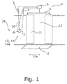
- the access control system is adapted for an access device 1 of a vehicle, wherein the access device 1 is a vehicle door 2 of a rail vehicle, of which only an interior 2a is shown here.
- the access control system comprises a sensor arrangement 3, which is specifically a laser scanner. This sensor arrangement 3 detects contact movement and especially a hand movement of a user in a spatial detection area 4.
- the access control system comprises a closing arrangement 5 which serves in a manner known per se for mechanical locking, mechanical unlocking and opening and closing of the vehicle door 2.
- the access control system comprises a processing device 6 which controls the closing arrangement 5 and which receives a signal from the sensor arrangement 3 when it has detected a user movement.
- the access control system comprises an operating body 7, which is formed by a disk-like projection and whose circular and curved front surface forms a reflection surface 8 for the diffuse scattering of incident light.
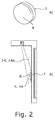
- the operating body 7 is rigid and immovable and is in the Fig. 2 shown enlarged.
- the reflection surface 8 has only one reflection region.
- the reflection surface 8 could have a plurality of reflection regions each having different reflection properties.
- the access control system comprises a projection device 9, which is a light emitter and which emits a cone of light 10 on the reflection surface 8, wherein the light of the light cone 10 is reflected by the reflection surface 8.
- the light cone 10 is colored and in this particular case illustrated green, as im in the Fig. 1 illustrated state, the access device 1 is unlocked.
- the projection device 9 can also change the color of the light cone 10 and, for example, emit a red cone of light 10.
- the light cone 10 extends in a cross-sectional projection substantially vertically downwards, wherein the schematic representation of Fig. 2b for illustration purposes deviates slightly more from this vertical course.
- the cylindrical detection area 4 is formed by a volume in front of the reflection surface 8, which is defined in front of the reflection surface 8 essentially by a maximum distance profile, which distance is presently constant. This volume adjoins the reflection surface 8 and can also be referred to as the proximity region 4a. A contact of the reflection surface 8 is thus detected as user movement by the sensor arrangement 3.
- a current access lock state of the access device 1 is maintained, which in the present case is an unlocked state as stated above. In this unlocked state, the detection of a user movement causes the vehicle door 2 to be opened by the closing arrangement 5, as shown.
- the access device 1 may also assume a locked state as an access lock state, for example, during a travel of the vehicle. Then, the projection device 9 emits a red light cone 10 and a user movement detected by the sensor arrangement 3 does not trigger opening of the vehicle door 2.
- the vehicle door 2 has a door leaf 11, with which a door opening 12 can be optionally closed or released. It can also be seen that the projection device 9 is arranged essentially above the door opening 12 with respect to a transverse direction 12 a of the vehicle, that is to say in accordance with a transverse view of the vehicle.
- This door opening 12 is located next to a vehicle wall 13, on which vehicle wall 13 of the operating body 7 is arranged.
- the vehicle wall 13 forms a flat carrier wall 14, from which the one surface of the operating body 7 is deposited, which forms the reflection surface 8.
- the support wall 14 itself in turn forms an inner surface 14a of the vehicle.
- an arrangement of the operating body 7 on the door leaf 11 would be conceivable, either on an inner side of the door leaf 11 or on an outer side of the door leaf 11. It would also be conceivable to arrange the operating body 7 with the reflection surface 8 on an outer surface of the vehicle, which outer surface is formed by the outer side of the vehicle wall 13.
Landscapes
- Engineering & Computer Science (AREA)
- Mechanical Engineering (AREA)
- Lock And Its Accessories (AREA)
- Power-Operated Mechanisms For Wings (AREA)
Abstract
Die Erfindung betrifft ein Zugangssteuersystem für eine Zugangsvorrichtung (1) eines Fahrzeugs, umfassend eine Sensoranordnung (3) zur berührungslosen Erfassung einer Benutzerbewegung in einem Erfassungsbereich (4) im Bereich der Zugangsvorrichtung (1), umfassend eine Schließanordnung (5) zum Betätigen der Zugangsvorrichtung (1) und umfassend eine Verarbeitungsvorrichtung (6) zum Ansteuern der Schließanordnung (5) basierend auf einer von der Sensoranordnung (3) erfassten Benutzerbewegung. Das Zugangssteuersystem ist dadurch gekennzeichnet, dass das Zugangssteuersystem eine im Bereich der Zugangsvorrichtung (1) angeordnete Reflexionsoberfläche (8) zum Reflektieren von Licht und eine Projektionsvorrichtung (9) zum Ausstrahlen eines Lichtkegels (10) im sichtbaren Bereich auf die Reflexionsoberfläche (8) aufweist und dass die Reflexionsoberfläche (8) im Wesentlichen am Erfassungsbereich (4) angeordnet ist. Ebenso betrifft die Erfindung ein entsprechendes Verfahren zum Steuern einer Zugangsvorrichtung.The invention relates to an access control system for an access device (1) of a vehicle, comprising a sensor arrangement (3) for contactless detection of user movement in a detection area (4) in the area of the access device (1), comprising a closing arrangement (5) for operating the access device (5). 1) and comprising a processing device (6) for driving the closing arrangement (5) based on a user movement detected by the sensor arrangement (3). The access control system is characterized in that the access control system comprises a reflection surface (8) arranged in the area of the access device (1) for reflecting light and a projection device (9) for radiating a light cone (10) in the visible region onto the reflection surface (8) and the reflection surface (8) is arranged substantially at the detection area (4). Likewise, the invention relates to a corresponding method for controlling an access device.
Description
Die Erfindung betrifft ein Zugangssteuersystem für eine Zugangsvorrichtung eines Fahrzeugs mit den Merkmalen des Oberbegriffs von Anspruch 1 sowie ein Verfahren zum Steuern einer Zugangsvorrichtung eines Fahrzeugs mit den Merkmalen des Oberbegriffs von Anspruch 15.The invention relates to an access control system for an access device of a vehicle having the features of the preamble of
Das Betätigen von Zugangsvorrichtungen bei Fahrzeugen, zu welchen Zugangsvorrichtungen in erster Linie Fahrzeugtüren zählen, wird mithilfe einer Sensorik gesteuert, welche entsprechende Benutzerbewegungen oder Benutzerbetätigungen erfasst, worauf eine Betätigung bzw. Öffnung der Zugangsvorrichtung veranlasst wird. Insbesondere bei Fahrzeugen des öffentlichen Personenverkehrs wurden in der Vergangenheit jeweils mehrere Taster im Innen- wie im Außenraum des Fahrzeugs vorgesehen, durch deren Betätigung - jedenfalls bei freigegebener Tür - das Öffnen der Tür bewirkt werden konnte. Auf diese Weise wurde Passagieren der Ein- und Ausstieg erlaubt. Nachteilig an diesem Ansatz ist, dass durch die verteilte Anordnung der Taster eine ausgedehnte Verkabelung erforderlich war. Ebenso war durch die mechanische Ausgestaltung der Taster stets ein gewisses Risiko an Ausfällen oder Beschädigungen gegeben.The actuation of access devices on vehicles, to which access devices primarily count vehicle doors, is controlled by means of a sensor which detects corresponding user movements or user actions, whereupon an actuation or opening of the access device is initiated. In particular, in the case of public transport vehicles, several buttons were provided in the interior and in the outer space of the vehicle in the past, through the actuation of which - at least when the door was released - the door could be opened. In this way, passengers were allowed entry and exit. A disadvantage of this approach is that an extensive wiring was required by the distributed arrangement of the probe. Likewise, due to the mechanical configuration of the buttons, there was always a certain risk of failure or damage.
Die Offenlegungsschrift
Allerdings haben die herkömmlichen elektromechanischen Taster regelmäßig auch die Funktion gehabt, den aktuellen Freigabe- oder Verriegelungszustand der entsprechenden Fahrzeugtür anzuzeigen, z. B. durch eine entsprechend farbige Leuchtanzeige. Auf diese Weise können die Fahrgäste erkennen, ob eine Öffnung der Fahrzeugtür aktuell möglich ist oder nicht. Nicht möglich ist eine Öffnung beispielsweise dann, wenn das Fahrzeug noch nicht die vorgeschriebene Halteposition erreicht hat. Das Vorsehen einer solchen Anzeige verhindert Frust der dann eintreten kann, wenn trotz Betätigung des Tasters keine Öffnung der Tür erfolgt und der Grund für den Fahrgast nicht ohne weiteres erkennbar ist. Eine solche unterschiedlich leuchtende Anzeigevorrichtung setzt herkömmlicherweise eine entsprechende Verkabelung voraus.However, the conventional electromechanical buttons have also regularly had the function to indicate the current release or locking state of the corresponding vehicle door, z. B. by a correspondingly colored indicator. In this way, the passengers can recognize whether an opening of the vehicle door is currently possible or not. Not possible is an opening for example, when the vehicle has not yet reached the prescribed stop position. The provision of such a display prevents frustration that can then occur if, despite the operation of the button, no opening of the door and the reason for the passenger is not readily apparent. Such a differently illuminating display device conventionally requires a corresponding wiring.
Ausgehend von diesem Stand der Technik besteht die Aufgabe der Erfindung darin, die bekannte Steuerung einer Fahrzeugtür dahingehend weiterzuentwickeln und zu verbessern, dass der Bedarf für Verkabelungen - insbesondere in beweglichen Teilen - sowie für sonstige verteilte elektrische oder mechanische Vorrichtungen verringert oder komplett vermieden und der Bedienkomfort verbessert wird.Based on this prior art, the object of the invention is to further develop and improve the known control of a vehicle door so that the need for wiring - especially in moving parts - as well as other distributed electrical or mechanical devices reduced or completely avoided and ease of use is improved.
Diese Aufgabe wird für ein Zugangssteuersystem für eine Zugangsvorrichtung eines Fahrzeugs mit den Merkmalen des Oberbegriffs von Anspruch 1 durch die Merkmale des kennzeichnenden Teils von Anspruch 1 gelöst. Für ein Verfahren zum Steuern einer Zugangsvorrichtung eines Fahrzeugs mit den Merkmalen des Oberbegriffs von Anspruch 1 wird diese Aufgabe durch die Merkmale des kennzeichnenden Teils von Anspruch 1 gelöst.This object is achieved for an access control system for an access device of a vehicle having the features of the preamble of
Wesentlich für die Erfindung ist die Erkenntnis, dass nicht nur die Erfassung der Benutzerbewegung zur Ansteuerung der Zugangsvorrichtung berührungslos erfolgen kann, sondern dem Benutzer auch der Zustand der Zugangsvorrichtung auf eine Art und Weise kommuniziert werden kann, welche ebenfalls ohne das Vorsehen einer Leitung auskommt. Speziell kann hierzu eine Reflexionsoberfläche angestrahlt werden, was aus Sicht des Benutzers dieselbe Wirkung hat wie eine Leuchtvorrichtung an der Stelle der Reflexionsoberfläche. Analog zur Erfassung der Benutzerbewegung erfolgt also auch die Übertragung einer Zustandsinformation "berührungslos". Durch die räumliche Nähe zwischen dem Erfassungsbereich und der Reflexionsoberfläche ist der Zusammenhang zwischen der möglichen Betätigung und der Zustandsanzeige für den Benutzer intuitiv erkennbar.Essential to the invention is the realization that not only the detection of the user movement to control the access device can be done without contact, but the user can also communicate the state of the access device in a manner which also manages without the provision of a line. Specifically, for this purpose, a reflection surface can be illuminated, which has the same effect from the user's point of view as a lighting device at the location of the reflection surface. Analogously to the detection of the user movement, therefore, the transmission of a state information takes place "contactlessly". Due to the spatial proximity between the detection area and the reflection surface, the connection between the possible actuation and the status display is intuitively recognizable to the user.
Das erfindungsgemäße Zugangssteuersystem ist für eine Zugangsvorrichtung eines Fahrzeugs und umfasst eine Sensoranordnung zur berührungslosen Erfassung einer Benutzerbewegung in einem Erfassungsbereich. Dieser Erfassungsbereich befindet sich im Bereich der Zugangsvorrichtung. Der Erfassungsbereich ist derjenige Bereich, für den die Sensoranordnung zur Erfassung der Benutzerbewegung eingerichtet ist. Bei der Benutzerbewegung kann es sich insbesondere um eine Handbewegung des Benutzers handeln. Speziell kann eine solche Benutzerbewegung erfasst werden, sobald eine Hand des Benutzers in den Erfassungsbereich bewegt wird. Eine Benutzerbewegung außerhalb des Erfassungsbereichs wird entweder gar nicht von der Sensoranordnung registriert oder als außerhalb des vorgeschriebenen Erfassungsbereichs erfolgende Benutzerbewegung verworfen. Dass der Erfassungsbereich sich im Bereich der Zugangsvorrichtung befindet kann bedeuten, dass der Abstand zwischen dem Erfassungsbereich und der Zugangsvorrichtung weniger als 3 m, vorzugsweise weniger als 2 m und insbesondere weniger als 1 m oder gar weniger als 50 cm beträgt. Bevorzugt handelt es sich bei dem Fahrzeug um ein Fahrzeug des öffentlichen Personenverkehrs, insbesondere um ein Schienenfahrzeug zur Personenbeförderung oder um einen Bus zur Personenbeförderung.The access control system according to the invention is for an access device of a vehicle and comprises a sensor arrangement for the contactless detection of a user movement in a detection area. This coverage area is located in the area of the access device. The detection area is the area for which the sensor arrangement is set up to detect the user movement. The user movement may in particular be a hand movement of the user. Specifically, such a user movement can be detected as soon as a user's hand is moved into the detection area. A user movement outside the detection area is either not registered by the sensor arrangement or rejected as a user movement outside the prescribed detection area. The fact that the detection area is in the area of the access device may mean that the distance between the detection area and the access device is less than 3 m, preferably less than 2 m and in particular less than 1 m or even less than 50 cm. The vehicle is preferably a vehicle of public passenger transport, in particular a rail vehicle for passenger transport or a bus for passenger transport.
Das erfindungsgemäße Zugangssteuersystem umfasst ferner eine Schließanordnung zum Betätigen der Zugangsvorrichtung und umfasst eine Verarbeitungsvorrichtung zum Ansteuern der Schließanordnung basierend auf einer von der Sensoranordnung erfassten Benutzerbewegung. Dies kann insbesondere bedeuten, auf eine erfasste Benutzerbewegung hin die Schließanordnung zum Betätigen der Zugangsvorrichtung anzusteuern. Eine solche Schließanordnung für eine Zugangsvorrichtung ist an sich aus dem Stand der Technik bekannt. Dabei kann die Ansteuerung der Schließanordnung auch von einem aktuellen Zustand abhängen und insbesondere davon abhängen, ob eine solche Betätigung der Zugangsvorrichtung aktuell freigegeben ist.The access control system according to the invention further comprises a closing arrangement for actuating the access device and comprises a processing device for actuating the closing arrangement based on a user movement detected by the sensor arrangement. This may mean, in particular, to actuate the closing arrangement for actuating the access device in response to a detected user movement. Such a closure arrangement for an access device is known per se from the prior art. In this case, the activation of the closing arrangement can also depend on a current state and in particular depend on whether such an actuation of the access device is currently enabled.
Das erfindungsgemäße Zugangssteuersystem ist dadurch gekennzeichnet, dass das Zugangssteuersystem eine im Bereich der Zugangsvorrichtung angeordnete Reflexionsoberfläche zum Reflektieren von Licht und eine Projektionsvorrichtung zum Ausstrahlen eines Lichtkegels im sichtbaren Bereich auf die Reflexionsoberfläche aufweist und dass die Reflexionsoberfläche im Wesentlichen am Erfassungsbereich angeordnet ist. Der Lichtkegel kann im Wesentlichen auch die Form eines Zylinders haben, sodass also keine wesentliche Steigung eines Kegels erforderlich ist. Dass die Reflexionsoberfläche im Wesentlichen am Erfassungsbereich angeordnet ist kann auch bedeuten, dass der Abstand zwischen der Reflexionsoberfläche und dem Erfassungsbereich höchstens 20 cm, vorzugsweise höchstens 10 cm und insbesondere höchstens 5 cm beträgt. Die Reflexionsoberfläche kann auch im Erfassungsbereich oder unmittelbar angrenzend an den Erfassungsbereich angeordnet sein, sodass der Abstand zwischen der Reflexionsoberfläche und dem Erfassungsbereich 0 betragen würde.The access control system according to the invention is characterized in that the access control system has a reflection surface arranged in the area of the access device for reflecting light and a projection device for emitting a light cone in the visible area onto the reflection surface and that the reflection surface is arranged substantially at the detection area. The light cone can essentially also have the shape of a cylinder, so that no significant slope of a cone is required. The fact that the reflection surface is arranged essentially at the detection area can also mean that the distance between the reflection surface and the detection range is at most 20 cm, preferably at most 10 cm and in particular at most 5 cm. The reflection surface may also be arranged in the detection region or directly adjacent to the detection region, so that the distance between the reflection surface and the detection region would be zero.
Grundsätzlich kann es sich bei der Zugangsvorrichtung um eine beliebige Vorrichtung handeln, welche den Zugang zu dem Fahrzeug ermöglicht oder erleichtert. Insbesondere kann es sich bei der Zugangsvorrichtung um einen Schiebetritt oder um eine Trittstufe handeln. Eine bevorzugte Ausführungsform des Zugangssteuersystems ist dadurch gekennzeichnet, dass die Zugangsvorrichtung eine Fahrzeugtür aufweist und dass die Schließanordnung zum Schließen und Öffnen der Fahrzeugtür eingerichtet ist. Entsprechend kann es sich bevorzugt um die Fahrzeugtür eines Fahrzeugs des öffentlichen Personenverkehrs und weiter bevorzugt um eine Fahrzeugtür für einen Fahrgastraum des Fahrzeugs des öffentlichen Personenverkehrs handeln.In principle, the access device can be any device that allows or facilitates access to the vehicle. In particular, the access device may be a sliding step or a step. A preferred embodiment of the access control system is characterized in that the access device comprises a vehicle door and that the closing arrangement is arranged for closing and opening the vehicle door. Accordingly, it can preferably be the vehicle door of a public transport vehicle, and more preferably a vehicle door for a passenger compartment of the public transport vehicle.
Eine weitere bevorzugte Ausführungsform des Zugangssteuersystems ist dadurch gekennzeichnet, dass die Fahrzeugtür einen Türflügel umfasst, welcher zum Verschließen und Freigeben einer Türöffnung neben einer Fahrzeugwand des Fahrzeugs bei Schließen und Öffnen der Fahrzeugtür eingerichtet ist. Ein solcher Türflügel ist vorzugsweise beweglich zur Fahrzeugwand gelagert. Ebenso vorzugsweise ist die Reflexionsoberfläche im Bereich des Türflügels oder im Bereich der Fahrzeugwand angeordnet. Insbesondere kann es auch sein, dass die Reflexionsoberfläche durch eine Oberfläche des Türflügels oder durch eine Oberfläche der Fahrzeugwand gebildet ist. Indem auf diese Weise ein herkömmlicher Taster an dem Türflügel ersetzt wird, kann die entsprechende Verkabelung an dem Türflügel, welche durch die Beweglichkeit des Türflügels aufwändig in der Bereitstellung ist, vorteilhafterweise entfallen.A further preferred embodiment of the access control system is characterized in that the vehicle door comprises a door which is arranged for closing and releasing a door opening adjacent to a vehicle wall of the vehicle when closing and opening the vehicle door. Such a door is preferably mounted movably to the vehicle wall. Also preferably, the reflection surface is arranged in the region of the door leaf or in the region of the vehicle wall. In particular, it may also be that the reflection surface is formed by a surface of the door leaf or by a surface of the vehicle wall. By replacing in this way a conventional button on the door leaf, the corresponding wiring to the door leaf, which is complicated by the mobility of the door leaf in the provision, advantageously eliminated.
Gemäß einer bevorzugten Ausführungsform des Zugangssteuersystems ist vorgesehen, dass die Projektionsvorrichtung zum Ausstrahlen eines farbigen Lichtkegels auf die Reflexionsoberfläche eingerichtet ist. Unter einem farbigen Lichtkegel ist hier gemäß der üblichen Bedeutung ein Lichtkegel mit einer nichtweißen Farbe zu verstehen. Vorzugsweise ist die Projektionsvorrichtung zum Ausstrahlen eines im Wesentlichen auf die Reflexionsoberfläche begrenzten Lichtkegels eingerichtet. Anders ausgedrückt ist der Lichtkegel im Wesentlichen auf die Reflexionsoberfläche begrenzt. Insbesondere kann es sein, dass die Projektionsvorrichtung zum Ausstrahlen eines Lichtkegels auf die Reflexionsoberfläche bei geschlossener Fahrzeugtür eingerichtet ist. Mit anderen Worten ist bei einer positionsveränderlichen Reflexionsoberfläche die Position der Reflexionsoberfläche bei geschlossener Fahrzeugtür maßgeblich.According to a preferred embodiment of the access control system, it is provided that the projection device is set up to emit a colored light cone on the reflection surface. Under a colored cone of light is here to understand a light cone with a non-white color according to the usual meaning. The projection device is preferably designed to emit a light cone which is essentially limited to the reflection surface. In other words, the cone of light is substantially limited to the reflection surface. In particular, it may be that the projection device is set up to emit a light cone on the reflection surface when the vehicle door is closed. In other words, in the case of a positionally variable reflection surface, the position of the reflection surface when the vehicle door is closed is decisive.
Eine bevorzugte Ausführungsform des Zugangssteuersystems ist dadurch gekennzeichnet, dass das Zugangssteuersystem einen Bedienkörper umfasst, wobei die Reflexionsoberfläche durch eine Oberfläche des Bedienkörpers gebildet ist. Prinzipiell kann es sich bei dem Bedienkörper um eine beliebige körperliche Struktur handeln. Insbesondere kann es sein, dass das Zugangssteuersystem eine flächige Trägerwand aufweist, auf der der Bedienkörper derart angeordnet ist, dass die die Reflexionsoberfläche bildende Oberfläche von der Wandfläche der Trägerwand abgesetzt ist. Auf diese Weise ist der Bedienkörper für den Benutzer auch haptisch leicht zu identifizieren. Hier ist es bevorzugt, dass eine Wand des Türflügels oder eine Wand der Fahrzeugwand die Trägerwand bildet. Entsprechend ist es bevorzugt, dass der Bedienkörper an dem Türflügel oder an der Fahrzeugwand befestigt und/oder angeordnet ist.A preferred embodiment of the access control system is characterized in that the access control system comprises an operating body, wherein the reflection surface is formed by a surface of the operating body. In principle, the operating body can be any physical structure. In particular, it may be that the access control system has a flat support wall on which the operating body is arranged such that the surface forming the reflection surface is offset from the wall surface of the support wall. In this way, the operating body for the user is also haptic easy to identify. Here it is preferred that a wall of the door leaf or a wall of the vehicle wall forms the support wall. Accordingly, it is preferred that the operating body is fastened and / or arranged on the door wing or on the vehicle wall.
Eine weitere bevorzugte Ausführungsform des Zugangssteuersystems ist dadurch gekennzeichnet, dass der Bedienkörper für eine Betätigung des Benutzers im Wesentlichen starr ist. Das bedeutet insbesondere, dass der Bedienkörper sich auf eine Berührung oder Betätigung durch den Benutzer nicht verformt. Dies ermöglicht eine besonders einfache Konstruktion des Bedienkörpers. Vorzugsweise bewirkt dies, dass der Bedienkörper auf die Betätigung im Wesentlichen feststeht und unverformt bleibt. Neben der fehlenden Verformung findet also auf eine Berührung oder Betätigung des Bedienkörpers auch keine Bewegung oder Verschiebung des Bedienkörpers statt.A further preferred embodiment of the access control system is characterized in that the operating body for an actuation of the user is substantially rigid. This means in particular that the operating body does not deform on a touch or operation by the user. This allows a particularly simple construction of the operating body. This preferably has the effect that the operating body is substantially fixed to the actuation and remains undeformed. In addition to the lack of deformation so there is no movement or displacement of the operating body to a touch or actuation of the control body.
Gemäß einer bevorzugten Ausführungsform des Zugangssteuersystems ist vorgesehen, dass die Reflexionsoberfläche in einem Innenraum des Fahrzeugs angeordnet ist. Insbesondere kann es sich um einen Fahrgastinnenraum des Fahrzeugs handeln. Vorzugsweise bildet dann die Trägerwand eine Innenfläche des Fahrzeugs. Alternativ kann es sein, dass die Reflexionsoberfläche außerhalb des Innenraums des Fahrzeugs und insbesondere außerhalb des Fahrgastinnenraums des Fahrzeugs angeordnet ist. Bevorzugt ist es dann, dass die Trägerwand eine Außenfläche des Fahrzeugs bildet.According to a preferred embodiment of the access control system, it is provided that the reflection surface is arranged in an interior of the vehicle. In particular, it may be a passenger compartment of the vehicle. Preferably, then, the support wall forms an inner surface of the vehicle. Alternatively, it may be that the reflection surface outside the interior of the vehicle and in particular outside the passenger compartment of the vehicle is arranged. It is then preferred that the support wall forms an outer surface of the vehicle.
Eine bevorzugte Ausführungsform des Zugangssteuersystems ist dadurch gekennzeichnet, dass die Projektionsvorrichtung bezogen auf eine Querrichtung des Fahrzeugs im Wesentlichen oberhalb der Fahrzeugtür, insbesondere im Wesentlichen oberhalb der Türöffnung, angeordnet ist. Dies erlaubt eine sehr kompakte Bauweise des Zugangssteuersystems insgesamt mit einem Minimum an Verkabelungsbedarf. Hier ist es weiter bevorzugt, dass die Projektionsvorrichtung den Lichtkegel in einer Querschnittsprojektion im Wesentlichen senkrecht nach unten ausstrahlt. Die Querschnittsebene ist hier vorzugsweise durch die Längsrichtung des Fahrzeugs definiert und somit zu dieser senkrecht. Mit anderen Worten kann der Verlauf des Lichtkegels eine Komponente in Längsrichtung des Fahrzeugs aufweisen, welche dann aber für die vorliegende Frage des senkrechten Verlaufs keine Rolle spielt.A preferred embodiment of the access control system is characterized in that the projection device with respect to a transverse direction of the vehicle is arranged substantially above the vehicle door, in particular substantially above the door opening. This allows a very compact design of the access control system overall with a minimum of cabling needs. Here, it is further preferred that the projection device emits the cone of light in a cross-sectional projection substantially vertically downwards. The cross-sectional plane is here preferably defined by the longitudinal direction of the vehicle and thus perpendicular to this. In other words, the course of the light cone may have a component in the longitudinal direction of the vehicle, which then, however, does not play any role in the present question of the vertical course.
Eine weitere bevorzugte Ausführungsform des Zugangssteuersystems ist dadurch gekennzeichnet, dass die Verarbeitungsvorrichtung zum Ansteuern der Schließanordnung auch basierend auf einem aktuellen Zugangsverriegelungszustand eingerichtet ist und dass die Projektionsvorrichtung dazu eingerichtet ist, basierend auf dem aktuellen Zugangsverriegelungszustand Licht in unterschiedlicher Farbe auszustrahlen. Dieser Zugangsverriegelungszustand kann einerseits eine jeweils andere mechanische Konfiguration in Abhängigkeit des Zugangsverriegelungszustands bedeuten. Der Zugangsverriegelungszustand kann aber auch rein elektrisch oder informationstechnisch realisiert sein, so etwa als interner Zustand der bevorzugt elektronischen Verarbeitungsvorrichtung. Durch dieses Verhalten bzw. diese Beschaffenheit der Projektionsvorrichtung kann dieser aktuelle Verriegelungszustand, welcher für das Verhalten der Verarbeitungsvorrichtung und damit der Schließanordnung relevant ist, einem Bediener auf eine Art und Weise kommuniziert werden, welcher der Art der herkömmlichen Tastervorrichtungen aus dem Bereich der Fahrzeuge des öffentlichen Personenverkehrs entspricht.Another preferred embodiment of the access control system is characterized in that the processing device is arranged to drive the locking assembly also based on a current access locking state and that the projection device is adapted to emit light of different colors based on the current access locking state. This access lock state may mean, on the one hand, a different mechanical configuration depending on the access lock state. However, the access locked state can also be realized purely electrically or in terms of information technology, for example as the internal state of the preferably electronic processing device. By virtue of this behavior or nature of the projection device, this current locking state, which is relevant to the behavior of the processing device and thus of the locking arrangement, can be communicated to an operator in a manner which is the nature of the conventional push button devices in the field of public vehicles Passenger traffic corresponds.
Gemäß einer bevorzugten Ausführungsform des Zugangssteuersystems ist vorgesehen, dass der aktuelle Zugangsverriegelungszustand ein verriegelter Zustand der Zugangsvorrichtung oder ein entriegelter Zustand der Zugangsvorrichtung sein kann. Neben diesen beiden Zugangsverriegelungszuständen kann es auch noch weitere Zugangsverriegelungszustände geben. Ebenso kann es mehrere Unterzustände des verriegelten Zustands oder des entriegelten Zustands geben, sodass es im Ergebnis auch mehrere Arten des verriegelten Zustands und des entriegelten Zustands geben kann. Hier ist es weiter bevorzugt, dass bei geschlossener Fahrzeugtür und einem entriegelten Zustand der Fahrzeugtür als aktuellem Zugangsverriegelungszustand auf die erfasste Benutzerbewegung die Schließanordnung die Fahrzeugtür öffnet. Insbesondere kann es weiter sein, dass bei geschlossener Fahrzeugtür und einem verriegelten Zustand der Fahrzeugtür als aktuellem Zugangsverriegelungszustand auf die erfasste Benutzerbewegung die Schließanordnung die Fahrzeugtür geschlossen lässt. Dies entspricht dem herkömmlichen Verhalten der Fahrzeugtür auf eine Betätigung durch den Benutzer.According to a preferred embodiment of the access control system it is provided that the current access locked state may be a locked state of the access device or an unlocked state of the access device. Besides these two access locking states it can also give further access locking states. Likewise, there may be multiple sub-states of the locked state or the unlocked state, so that, as a result, there may also be multiple types of the locked state and the unlocked state. Here it is further preferred that when the vehicle door is closed and the vehicle door is unlocked as the current access locked state to the detected user movement, the closing arrangement opens the vehicle door. In particular, it may be further that with the vehicle door closed and a locked state of the vehicle door as the current access locked state to the detected user movement, the closing arrangement keeps the vehicle door closed. This corresponds to the conventional behavior of the vehicle door upon actuation by the user.
Eine bevorzugte Ausführungsform des Zugangssteuersystems ist dadurch gekennzeichnet, dass die Reflexionsoberfläche zur diffusen Streuung von einfallendem Licht eingerichtet ist. Dies verbessert die Sichtbarkeit der Reflexionswirkung. Es kann ebenfalls sein, dass die Reflexionsoberfläche eine Vielzahl von Reflexionsbereichen aufweist, wobei jeder Reflexionsbereich dazu eingerichtet ist, das Licht unterschiedlich zu reflektieren. Auf diese Weise können Symbole oder Schriftzeichen auf der Reflexionsoberfläche wiedergegeben werden. Speziell kann jeder Reflexionsbereich dazu eingerichtet sein, das Licht in einer unterschiedlichen Farbe zu reflektieren. Hier ist es weiter bevorzugt, dass die Projektionsvorrichtung dazu eingerichtet ist, beispielsweise basierend auf dem aktuellen Zugangsverriegelungszustand einen unterschiedlichen Reflexionsbereich mit dem Lichtkegel anzustrahlen. Auf diese Weise kann auch ohne Änderung der Farbe des Lichtkegels eine Reflexion durch die Reflexionsoberfläche in einer jeweils unterschiedlichen Farbe erreicht werden.A preferred embodiment of the access control system is characterized in that the reflection surface is arranged for the diffuse scattering of incident light. This improves the visibility of the reflection effect. It may also be that the reflection surface has a plurality of reflection regions, each reflection region being adapted to reflect the light differently. In this way, symbols or characters can be displayed on the reflection surface. Specifically, each reflection area may be configured to reflect the light in a different color. Here, it is further preferred that the projection device is set up, for example, to illuminate a different reflection region with the light cone based on the current access locking state. In this way, even without changing the color of the cone of light, a reflection can be achieved by the reflection surface in a different color.
Eine weitere bevorzugte Ausführungsform des Zugangssteuersystems ist dadurch gekennzeichnet, dass der Erfassungsbereich einen Nahbereich angrenzend an die Reflexionsoberfläche umfasst. Auf diese Weise wird erreicht, dass für den Benutzer scheinbar die Berührung oder Betätigung der Reflexionsoberfläche die Ansteuerung der Schließanordnung und die Betätigung der Zugangsvorrichtung auslöst. Hier ist es weiter bevorzugt, dass der Erfassungsbereich im Wesentlichen aus dem Nahbereich besteht.A further preferred embodiment of the access control system is characterized in that the detection area comprises a proximity area adjacent to the reflection surface. In this way, it is achieved that for the user apparently the touch or actuation of the reflection surface triggers the activation of the closing arrangement and the operation of the access device. Here it is further preferred that the detection area essentially consists of the near area.
Gemäß einer bevorzugten Ausführungsform des Zugangssteuersystems ist vorgesehen, dass der Nahbereich vor der Reflexionsoberfläche im Wesentlichen ein Nahvolumen umfasst und vorzugsweise aus diesem gebildet wird. Vorzugsweise wird dieses Nahvolumen durch einen vorzugsweise im Wesentlichen konstanten maximalen Abstand zu der Reflexionsoberfläche gebildet wird. Mit anderen Worten entspricht das durch diesen Abstand definierte und entsprechend durch die Reflexionsoberfläche begrenzte Volumen - also das Nahvolumen - im Wesentlichen dem Nahbereich. Auf diese Weise wird der Anschein einer mechanischen Betätigung der Reflexionsoberfläche für den Benutzer besonders täuschend echt.According to a preferred embodiment of the access control system, it is provided that the near zone in front of the reflection surface essentially comprises a near volume and is preferably formed from this. Preferably, this near volume is formed by a preferably substantially constant maximum distance to the reflection surface. In other words, the volume defined by this distance and correspondingly limited by the reflection surface-that is, the near volume-substantially corresponds to the near zone. In this way, the appearance of a mechanical operation of the reflection surface for the user is particularly deceptively real.
Eine bevorzugte Ausführungsform des Zugangssteuersystems ist dadurch gekennzeichnet, dass die Sensoranordnung dazu eingerichtet ist, durch Laserentfernungsmessung die Benutzerbewegung vorzugsweise in dem Erfassungsbereich zu erfassen. Es handelt sich dabei um das an sich aus dem Stand der Technik bekannte Prinzip, welches auch als Laserscanning bezeichnet wird. Hier kann es insbesondere sein, dass die Sensoranordnung - in ebenfalls an sich aus dem Stand der Technik bekannter Weise - dazu eingerichtet ist, die Benutzerbewegung basierend auf einer detektierten Punktwolke zu erfassen.A preferred embodiment of the access control system is characterized in that the sensor arrangement is set up to detect the user movement preferably in the detection area by means of laser distance measurement. This is the principle known per se from the prior art, which is also referred to as laser scanning. In this case, it may in particular be the case that the sensor arrangement-in a manner also known from the prior art-is set up to detect the user movement on the basis of a detected point cloud.
Das erfindungsgemäße Verfahren dient zum Steuern einer Zugangsvorrichtung eines Fahrzeugs, wobei eine Sensoranordnung eine Benutzerbewegung in einem Erfassungsbereich im Bereich der Zugangsvorrichtung berührungslos erfasst und wobei eine Verarbeitungsvorrichtung eine Schließanordnung zum Betätigen der Zugangsvorrichtung basierend auf der von der Sensoranordnung erfassten Benutzerbewegung ansteuert. Das erfindungsgemäße Verfahren ist dadurch gekennzeichnet, dass eine Projektionsvorrichtung einen Lichtkegel im sichtbaren Bereich auf eine Reflexionsoberfläche ausstrahlt, welche Reflexionsoberfläche auf sie einfallendes Licht reflektiert und dass die Reflexionsoberfläche im Wesentlichen im Erfassungsbereich angeordnet ist.The method according to the invention serves to control an access device of a vehicle, wherein a sensor arrangement senses a user movement in a detection area in the area of the access device without contact and wherein a processing device activates a closing arrangement for actuating the access device based on the user movement detected by the sensor arrangement. The method according to the invention is characterized in that a projection device emits a light cone in the visible region onto a reflection surface, which reflection surface reflects light incident on it, and that the reflection surface is arranged substantially in the detection region.
Bevorzugte Ausführungsformen des erfindungsgemäßen Verfahrens ergeben sich aus den Merkmalen, Eigenschaften und Einzelheiten bevorzugter Ausführungsformen des erfindungsgemäßen Zugangssteuersystems.Preferred embodiments of the method according to the invention emerge from the features, properties and details of preferred embodiments of the access control system according to the invention.
Weitere vorteilhafte und bevorzugte Ausgestaltungen ergeben sich aus der nachfolgenden Beschreibung mit Bezug auf die Figuren. In der lediglich ein Ausführungsbeispiel wiedergebenden Zeichnung zeigt
- Fig. 1
- eine schematische Darstellung eines Ausführungsbeispiels eines erfindungsgemäßen Zugangssteuersystems für eine Fahrgasttür eines Schienenfahrzeugs,
- Fig. 2a
- eine schematische und vergrößerte Perspektivansicht des Bedienkörpers des Zugangssteuersystems der
Fig. 1 und - Fig. 2b
- eine schematische Queransicht auf Teile des Zugangssteuersystems der
Fig. 1 .
- Fig. 1
- a schematic representation of an embodiment of an access control system according to the invention for a passenger door of a rail vehicle,
- Fig. 2a
- a schematic and enlarged perspective view of the operating body of the access control system of
Fig. 1 and - Fig. 2b
- a schematic cross-sectional view of parts of the access control system of
Fig. 1 ,
Das in der
Das Zugangssteuersystem umfasst einen Bedienkörper 7, welcher durch einen scheibenartigen Vorsprung gebildet wird und dessen kreisförmige und gewölbte Vorderfläche eine Reflexionsoberfläche 8 zur diffusen Streuung von einfallendem Licht bildet. Der Bedienkörper 7 ist starr und unbeweglich und wird in der
Ferner umfasst das Zugangssteuersystem eine Projektionsvorrichtung 9, bei welcher es sich um einen Lichtstrahler handelt und welche einen Lichtkegel 10 auf die Reflexionsoberfläche 8 ausstrahlt, wobei das Licht des Lichtkegels 10 von der Reflexionsoberfläche 8 reflektiert wird. Der Lichtkegel 10 ist farbig und in diesem speziellen dargestellten Fall grün, da im in der
Erkennbar wird der zylinderförmige Erfassungsbereich 4 durch ein Volumen vor der Reflexionsoberfläche 8 gebildet, welches im Wesentlichen durch einen maximalen Abstandsverlauf, welcher Abstand vorliegend konstant ist, vor der Reflexionsoberfläche 8 definiert ist. Dieses Volumen grenzt an die Reflexionsoberfläche 8 an und kann auch als Nahbereich 4a bezeichnet werden. Eine Berührung der Reflexionsoberfläche 8 wird somit als Benutzerbewegung durch die Sensoranordnung 3 erfasst. In der Verarbeitungsvorrichtung 6 wird ein aktueller Zugangsverriegelungszustand der Zugangsvorrichtung 1 vorgehalten, welcher vorliegend wie oben festgestellt ein entriegelter Zustand ist. In diesem entriegelten Zustand bewirkt das Erfassen einer Benutzerbewegung das Öffnen der Fahrzeugtür 2 - wie dargestellt - durch die Schließanordnung 5.It can be seen that the cylindrical detection area 4 is formed by a volume in front of the
Die Zugangsvorrichtung 1 kann auch einen verriegelten Zustand als Zugangsverriegelungszustand einnehmen, beispielsweise während einer Fahrt des Fahrzeugs. Dann strahlt die Projektionsvorrichtung 9 einen roten Lichtkegel 10 aus und eine von der Sensoranordnung 3 erfasste Benutzerbewegung löst kein Öffnen der Fahrzeugtür 2 aus.The
Wie wiederum in der
Diese Türöffnung 12 befindet sich neben einer Fahrzeugwand 13, auf welcher Fahrzeugwand 13 der Bedienkörper 7 angeordnet ist. Die Fahrzeugwand 13 bildet eine flächige Trägerwand 14, von welcher die diejenige Oberfläche des Bedienkörpers 7 abgesetzt ist, welche die Reflexionsoberfläche 8 bildet. Die Trägerwand 14 selbst wiederum bildet eine Innenfläche 14a des Fahrzeugs. Alternativ wäre auch eine Anordnung des Bedienkörpers 7 auf dem Türflügel 11 denkbar, und zwar entweder auf einer Innenseite des Türflügels 11 oder auf einer Außenseite des Türflügels 11. Ebenso wäre es denkbar, den Bedienkörper 7 mit der Reflexionsoberfläche 8 an einer Außenfläche des Fahrzeugs anzuordnen, welche Außenfläche durch die äußere Seite der Fahrzeugwand 13 gebildet wird.This door opening 12 is located next to a vehicle wall 13, on which vehicle wall 13 of the operating
Claims (15)
Priority Applications (3)
| Application Number | Priority Date | Filing Date | Title |
|---|---|---|---|
| ES16189524T ES2890661T3 (en) | 2016-09-19 | 2016-09-19 | Access control system for a vehicle access device |
| PL16189524T PL3296177T3 (en) | 2016-09-19 | 2016-09-19 | Access control system for an access device of a vehicle |
| EP16189524.8A EP3296177B1 (en) | 2016-09-19 | 2016-09-19 | Access control system for an access device of a vehicle |
Applications Claiming Priority (1)
| Application Number | Priority Date | Filing Date | Title |
|---|---|---|---|
| EP16189524.8A EP3296177B1 (en) | 2016-09-19 | 2016-09-19 | Access control system for an access device of a vehicle |
Publications (2)
| Publication Number | Publication Date |
|---|---|
| EP3296177A1 true EP3296177A1 (en) | 2018-03-21 |
| EP3296177B1 EP3296177B1 (en) | 2021-08-11 |
Family
ID=56979400
Family Applications (1)
| Application Number | Title | Priority Date | Filing Date |
|---|---|---|---|
| EP16189524.8A Active EP3296177B1 (en) | 2016-09-19 | 2016-09-19 | Access control system for an access device of a vehicle |
Country Status (3)
| Country | Link |
|---|---|
| EP (1) | EP3296177B1 (en) |
| ES (1) | ES2890661T3 (en) |
| PL (1) | PL3296177T3 (en) |
Cited By (1)
| Publication number | Priority date | Publication date | Assignee | Title |
|---|---|---|---|---|
| EP3882104A1 (en) * | 2020-03-19 | 2021-09-22 | Knorr-Bremse Gesellschaft mit beschränkter Haftung | Button for an entry system with at least one door for a railway vehicle and entry system with at least one door and one button |
Citations (10)
| Publication number | Priority date | Publication date | Assignee | Title |
|---|---|---|---|---|
| US4621452A (en) * | 1985-01-18 | 1986-11-11 | Deeg Wyman L | Powered sliding door safety system |
| WO1995025380A1 (en) * | 1994-03-17 | 1995-09-21 | Prospects Corporation | Power driven venting of a vehicle |
| DE19723974A1 (en) * | 1997-06-06 | 1998-12-17 | Draexlmaier Lisa Gmbh | Method for preventing a foreign object from being trapped and a trap protection system |
| US5955854A (en) * | 1992-09-29 | 1999-09-21 | Prospects Corporation | Power driven venting of a vehicle |
| EP1011184A1 (en) * | 1998-12-15 | 2000-06-21 | Talltec Technologies Holdings S.A. | Safety device for an electric motor-driven sliding panel and method for carrying out this arrangement |
| WO2006072617A2 (en) * | 2005-01-10 | 2006-07-13 | Siemens Aktiengesellschaft | System for monitoring the area between a train and the platform edge |
| DE202005011480U1 (en) * | 2005-07-21 | 2006-12-14 | Brose Fahrzeugteile Gmbh & Co. Kommanditgesellschaft, Coburg | Chassis part used a vehicle door comprises an anti-trapping device arranged in the in the region of a closing gap and having an emitter, reflector and/or receiver each having a cleaning element for removing dirt particles |
| DE102007001178A1 (en) * | 2007-01-05 | 2008-07-10 | Siemens Ag | Non-contact anti-trap protection |
| DE102014113567A1 (en) | 2014-09-19 | 2016-03-24 | Gebr. Bode Gmbh & Co. Kg | Door system with sensor unit for non-contact passenger compartment monitoring |
| DE102014113569A1 (en) * | 2014-09-19 | 2016-03-24 | Gebr. Bode Gmbh & Co. Kg | Door system with sensor unit and communication element |
-
2016
- 2016-09-19 ES ES16189524T patent/ES2890661T3/en active Active
- 2016-09-19 PL PL16189524T patent/PL3296177T3/en unknown
- 2016-09-19 EP EP16189524.8A patent/EP3296177B1/en active Active
Patent Citations (10)
| Publication number | Priority date | Publication date | Assignee | Title |
|---|---|---|---|---|
| US4621452A (en) * | 1985-01-18 | 1986-11-11 | Deeg Wyman L | Powered sliding door safety system |
| US5955854A (en) * | 1992-09-29 | 1999-09-21 | Prospects Corporation | Power driven venting of a vehicle |
| WO1995025380A1 (en) * | 1994-03-17 | 1995-09-21 | Prospects Corporation | Power driven venting of a vehicle |
| DE19723974A1 (en) * | 1997-06-06 | 1998-12-17 | Draexlmaier Lisa Gmbh | Method for preventing a foreign object from being trapped and a trap protection system |
| EP1011184A1 (en) * | 1998-12-15 | 2000-06-21 | Talltec Technologies Holdings S.A. | Safety device for an electric motor-driven sliding panel and method for carrying out this arrangement |
| WO2006072617A2 (en) * | 2005-01-10 | 2006-07-13 | Siemens Aktiengesellschaft | System for monitoring the area between a train and the platform edge |
| DE202005011480U1 (en) * | 2005-07-21 | 2006-12-14 | Brose Fahrzeugteile Gmbh & Co. Kommanditgesellschaft, Coburg | Chassis part used a vehicle door comprises an anti-trapping device arranged in the in the region of a closing gap and having an emitter, reflector and/or receiver each having a cleaning element for removing dirt particles |
| DE102007001178A1 (en) * | 2007-01-05 | 2008-07-10 | Siemens Ag | Non-contact anti-trap protection |
| DE102014113567A1 (en) | 2014-09-19 | 2016-03-24 | Gebr. Bode Gmbh & Co. Kg | Door system with sensor unit for non-contact passenger compartment monitoring |
| DE102014113569A1 (en) * | 2014-09-19 | 2016-03-24 | Gebr. Bode Gmbh & Co. Kg | Door system with sensor unit and communication element |
Cited By (2)
| Publication number | Priority date | Publication date | Assignee | Title |
|---|---|---|---|---|
| EP3882104A1 (en) * | 2020-03-19 | 2021-09-22 | Knorr-Bremse Gesellschaft mit beschränkter Haftung | Button for an entry system with at least one door for a railway vehicle and entry system with at least one door and one button |
| WO2021185908A1 (en) * | 2020-03-19 | 2021-09-23 | Knorr-Bremse Gesellschaft Mit Beschränkter Haftung | Button unit for an entry system having at least one door for a rail vehicle, and entry system having at least one door and a button unit |
Also Published As
| Publication number | Publication date |
|---|---|
| ES2890661T3 (en) | 2022-01-21 |
| EP3296177B1 (en) | 2021-08-11 |
| PL3296177T3 (en) | 2022-01-03 |
Similar Documents
| Publication | Publication Date | Title |
|---|---|---|
| EP3099547B1 (en) | Assembly module | |
| DE102016211494B4 (en) | Control device for a motor vehicle | |
| EP2844528B1 (en) | Method for controlling a closure element arrangement of a motor vehicle | |
| EP3194241B1 (en) | Door system with sensor unit and communication element | |
| DE102016216415B4 (en) | Method for controlling a display device for a motor vehicle and motor vehicle with a display device | |
| DE102013009673A1 (en) | Collision protection method and collision protection device for an adjustable vehicle part | |
| DE102012108004A1 (en) | Safety system for a motor vehicle door of a motor vehicle with at least two sensors | |
| DE102010056171A1 (en) | Method for automatically actuating a closing element of a vehicle and corresponding device and vehicle | |
| DE102016211495A1 (en) | Control device for a motor vehicle | |
| EP2038503B1 (en) | Passage gate | |
| DE102014222410B4 (en) | Access system for a vehicle | |
| DE102022104046A1 (en) | Vehicle door for a motor vehicle and method for operating such a vehicle door | |
| DE202010006996U1 (en) | Locking system for a motor vehicle door | |
| DE102014015403A1 (en) | Operating device for controlling at least one function of at least one motor vehicle side device | |
| DE102014001321A1 (en) | Method for operating at least one operating element for a vehicle door of a motor vehicle and motor vehicle | |
| EP3296177A1 (en) | Access control system for an access device of a vehicle | |
| DE102016002778A1 (en) | Ventilation device for an interior of a motor vehicle | |
| EP2974938A1 (en) | Device and method for positioning an accessory and railway vehicle | |
| EP4544132A1 (en) | Exterior door handle for attachment to a side door or a motor vehicle | |
| EP1273494B1 (en) | Vehicle interior monitoring device | |
| DE102022119083B4 (en) | Panel arrangement of a front end of a passenger car equipped with a storage compartment and operating method | |
| DE102018005464B4 (en) | Vehicle door or hatch and method for operating a vehicle door or hatch | |
| DE102022105504A1 (en) | Modular component for a movable part of a vehicle and a method for producing a modular component | |
| DE102022104044A1 (en) | Vehicle door for a motor vehicle and method for operating such a vehicle door | |
| DE202016106557U1 (en) | Vehicle with a converter arrangement |
Legal Events
| Date | Code | Title | Description |
|---|---|---|---|
| PUAI | Public reference made under article 153(3) epc to a published international application that has entered the european phase |
Free format text: ORIGINAL CODE: 0009012 |
|
| STAA | Information on the status of an ep patent application or granted ep patent |
Free format text: STATUS: THE APPLICATION HAS BEEN PUBLISHED |
|
| AK | Designated contracting states |
Kind code of ref document: A1 Designated state(s): AL AT BE BG CH CY CZ DE DK EE ES FI FR GB GR HR HU IE IS IT LI LT LU LV MC MK MT NL NO PL PT RO RS SE SI SK SM TR |
|
| AX | Request for extension of the european patent |
Extension state: BA ME |
|
| STAA | Information on the status of an ep patent application or granted ep patent |
Free format text: STATUS: REQUEST FOR EXAMINATION WAS MADE |
|
| 17P | Request for examination filed |
Effective date: 20180921 |
|
| RBV | Designated contracting states (corrected) |
Designated state(s): AL AT BE BG CH CY CZ DE DK EE ES FI FR GB GR HR HU IE IS IT LI LT LU LV MC MK MT NL NO PL PT RO RS SE SI SK SM TR |
|
| GRAP | Despatch of communication of intention to grant a patent |
Free format text: ORIGINAL CODE: EPIDOSNIGR1 |
|
| STAA | Information on the status of an ep patent application or granted ep patent |
Free format text: STATUS: GRANT OF PATENT IS INTENDED |
|
| INTG | Intention to grant announced |
Effective date: 20210322 |
|
| GRAS | Grant fee paid |
Free format text: ORIGINAL CODE: EPIDOSNIGR3 |
|
| GRAA | (expected) grant |
Free format text: ORIGINAL CODE: 0009210 |
|
| STAA | Information on the status of an ep patent application or granted ep patent |
Free format text: STATUS: THE PATENT HAS BEEN GRANTED |
|
| AK | Designated contracting states |
Kind code of ref document: B1 Designated state(s): AL AT BE BG CH CY CZ DE DK EE ES FI FR GB GR HR HU IE IS IT LI LT LU LV MC MK MT NL NO PL PT RO RS SE SI SK SM TR |
|
| REG | Reference to a national code |
Ref country code: CH Ref legal event code: EP |
|
| REG | Reference to a national code |
Ref country code: DE Ref legal event code: R096 Ref document number: 502016013585 Country of ref document: DE |
|
| REG | Reference to a national code |
Ref country code: IE Ref legal event code: FG4D Free format text: LANGUAGE OF EP DOCUMENT: GERMAN Ref country code: AT Ref legal event code: REF Ref document number: 1419116 Country of ref document: AT Kind code of ref document: T Effective date: 20210915 |
|
| REG | Reference to a national code |
Ref country code: NL Ref legal event code: FP |
|
| REG | Reference to a national code |
Ref country code: LT Ref legal event code: MG9D |
|
| REG | Reference to a national code |
Ref country code: ES Ref legal event code: FG2A Ref document number: 2890661 Country of ref document: ES Kind code of ref document: T3 Effective date: 20220121 |
|
| PG25 | Lapsed in a contracting state [announced via postgrant information from national office to epo] |
Ref country code: RS Free format text: LAPSE BECAUSE OF FAILURE TO SUBMIT A TRANSLATION OF THE DESCRIPTION OR TO PAY THE FEE WITHIN THE PRESCRIBED TIME-LIMIT Effective date: 20210811 Ref country code: SE Free format text: LAPSE BECAUSE OF FAILURE TO SUBMIT A TRANSLATION OF THE DESCRIPTION OR TO PAY THE FEE WITHIN THE PRESCRIBED TIME-LIMIT Effective date: 20210811 Ref country code: HR Free format text: LAPSE BECAUSE OF FAILURE TO SUBMIT A TRANSLATION OF THE DESCRIPTION OR TO PAY THE FEE WITHIN THE PRESCRIBED TIME-LIMIT Effective date: 20210811 Ref country code: PT Free format text: LAPSE BECAUSE OF FAILURE TO SUBMIT A TRANSLATION OF THE DESCRIPTION OR TO PAY THE FEE WITHIN THE PRESCRIBED TIME-LIMIT Effective date: 20211213 Ref country code: NO Free format text: LAPSE BECAUSE OF FAILURE TO SUBMIT A TRANSLATION OF THE DESCRIPTION OR TO PAY THE FEE WITHIN THE PRESCRIBED TIME-LIMIT Effective date: 20211111 Ref country code: FI Free format text: LAPSE BECAUSE OF FAILURE TO SUBMIT A TRANSLATION OF THE DESCRIPTION OR TO PAY THE FEE WITHIN THE PRESCRIBED TIME-LIMIT Effective date: 20210811 Ref country code: LT Free format text: LAPSE BECAUSE OF FAILURE TO SUBMIT A TRANSLATION OF THE DESCRIPTION OR TO PAY THE FEE WITHIN THE PRESCRIBED TIME-LIMIT Effective date: 20210811 Ref country code: BG Free format text: LAPSE BECAUSE OF FAILURE TO SUBMIT A TRANSLATION OF THE DESCRIPTION OR TO PAY THE FEE WITHIN THE PRESCRIBED TIME-LIMIT Effective date: 20211111 |
|
| REG | Reference to a national code |
Ref country code: DE Ref legal event code: R081 Ref document number: 502016013585 Country of ref document: DE Owner name: BODE - DIE TUER GMBH, DE Free format text: FORMER OWNER: GEBR. BODE GMBH & CO. KG, 34123 KASSEL, DE |
|
| PG25 | Lapsed in a contracting state [announced via postgrant information from national office to epo] |
Ref country code: LV Free format text: LAPSE BECAUSE OF FAILURE TO SUBMIT A TRANSLATION OF THE DESCRIPTION OR TO PAY THE FEE WITHIN THE PRESCRIBED TIME-LIMIT Effective date: 20210811 Ref country code: GR Free format text: LAPSE BECAUSE OF FAILURE TO SUBMIT A TRANSLATION OF THE DESCRIPTION OR TO PAY THE FEE WITHIN THE PRESCRIBED TIME-LIMIT Effective date: 20211112 |
|
| PG25 | Lapsed in a contracting state [announced via postgrant information from national office to epo] |
Ref country code: DK Free format text: LAPSE BECAUSE OF FAILURE TO SUBMIT A TRANSLATION OF THE DESCRIPTION OR TO PAY THE FEE WITHIN THE PRESCRIBED TIME-LIMIT Effective date: 20210811 |
|
| REG | Reference to a national code |
Ref country code: DE Ref legal event code: R097 Ref document number: 502016013585 Country of ref document: DE |
|
| REG | Reference to a national code |
Ref country code: BE Ref legal event code: MM Effective date: 20210930 |
|
| PG25 | Lapsed in a contracting state [announced via postgrant information from national office to epo] |
Ref country code: SM Free format text: LAPSE BECAUSE OF FAILURE TO SUBMIT A TRANSLATION OF THE DESCRIPTION OR TO PAY THE FEE WITHIN THE PRESCRIBED TIME-LIMIT Effective date: 20210811 Ref country code: SK Free format text: LAPSE BECAUSE OF FAILURE TO SUBMIT A TRANSLATION OF THE DESCRIPTION OR TO PAY THE FEE WITHIN THE PRESCRIBED TIME-LIMIT Effective date: 20210811 Ref country code: RO Free format text: LAPSE BECAUSE OF FAILURE TO SUBMIT A TRANSLATION OF THE DESCRIPTION OR TO PAY THE FEE WITHIN THE PRESCRIBED TIME-LIMIT Effective date: 20210811 Ref country code: MC Free format text: LAPSE BECAUSE OF FAILURE TO SUBMIT A TRANSLATION OF THE DESCRIPTION OR TO PAY THE FEE WITHIN THE PRESCRIBED TIME-LIMIT Effective date: 20210811 Ref country code: EE Free format text: LAPSE BECAUSE OF FAILURE TO SUBMIT A TRANSLATION OF THE DESCRIPTION OR TO PAY THE FEE WITHIN THE PRESCRIBED TIME-LIMIT Effective date: 20210811 Ref country code: AL Free format text: LAPSE BECAUSE OF FAILURE TO SUBMIT A TRANSLATION OF THE DESCRIPTION OR TO PAY THE FEE WITHIN THE PRESCRIBED TIME-LIMIT Effective date: 20210811 |
|
| PLBE | No opposition filed within time limit |
Free format text: ORIGINAL CODE: 0009261 |
|
| STAA | Information on the status of an ep patent application or granted ep patent |
Free format text: STATUS: NO OPPOSITION FILED WITHIN TIME LIMIT |
|
| 26N | No opposition filed |
Effective date: 20220512 |
|
| PG25 | Lapsed in a contracting state [announced via postgrant information from national office to epo] |
Ref country code: LU Free format text: LAPSE BECAUSE OF NON-PAYMENT OF DUE FEES Effective date: 20210919 Ref country code: IE Free format text: LAPSE BECAUSE OF NON-PAYMENT OF DUE FEES Effective date: 20210919 Ref country code: BE Free format text: LAPSE BECAUSE OF NON-PAYMENT OF DUE FEES Effective date: 20210930 |
|
| PG25 | Lapsed in a contracting state [announced via postgrant information from national office to epo] |
Ref country code: SI Free format text: LAPSE BECAUSE OF FAILURE TO SUBMIT A TRANSLATION OF THE DESCRIPTION OR TO PAY THE FEE WITHIN THE PRESCRIBED TIME-LIMIT Effective date: 20210811 |
|
| PG25 | Lapsed in a contracting state [announced via postgrant information from national office to epo] |
Ref country code: HU Free format text: LAPSE BECAUSE OF FAILURE TO SUBMIT A TRANSLATION OF THE DESCRIPTION OR TO PAY THE FEE WITHIN THE PRESCRIBED TIME-LIMIT; INVALID AB INITIO Effective date: 20160919 |
|
| PG25 | Lapsed in a contracting state [announced via postgrant information from national office to epo] |
Ref country code: CY Free format text: LAPSE BECAUSE OF FAILURE TO SUBMIT A TRANSLATION OF THE DESCRIPTION OR TO PAY THE FEE WITHIN THE PRESCRIBED TIME-LIMIT Effective date: 20210811 |
|
| PG25 | Lapsed in a contracting state [announced via postgrant information from national office to epo] |
Ref country code: MK Free format text: LAPSE BECAUSE OF FAILURE TO SUBMIT A TRANSLATION OF THE DESCRIPTION OR TO PAY THE FEE WITHIN THE PRESCRIBED TIME-LIMIT Effective date: 20210811 |
|
| PG25 | Lapsed in a contracting state [announced via postgrant information from national office to epo] |
Ref country code: MT Free format text: LAPSE BECAUSE OF FAILURE TO SUBMIT A TRANSLATION OF THE DESCRIPTION OR TO PAY THE FEE WITHIN THE PRESCRIBED TIME-LIMIT Effective date: 20210811 |
|
| PGFP | Annual fee paid to national office [announced via postgrant information from national office to epo] |
Ref country code: DE Payment date: 20240919 Year of fee payment: 9 |
|
| PGFP | Annual fee paid to national office [announced via postgrant information from national office to epo] |
Ref country code: GB Payment date: 20240923 Year of fee payment: 9 |
|
| PGFP | Annual fee paid to national office [announced via postgrant information from national office to epo] |
Ref country code: FR Payment date: 20240924 Year of fee payment: 9 |
|
| PGFP | Annual fee paid to national office [announced via postgrant information from national office to epo] |
Ref country code: NL Payment date: 20240920 Year of fee payment: 9 |
|
| PGFP | Annual fee paid to national office [announced via postgrant information from national office to epo] |
Ref country code: CZ Payment date: 20240910 Year of fee payment: 9 |
|
| PGFP | Annual fee paid to national office [announced via postgrant information from national office to epo] |
Ref country code: AT Payment date: 20240918 Year of fee payment: 9 |
|
| PGFP | Annual fee paid to national office [announced via postgrant information from national office to epo] |
Ref country code: PL Payment date: 20240910 Year of fee payment: 9 |
|
| PGFP | Annual fee paid to national office [announced via postgrant information from national office to epo] |
Ref country code: TR Payment date: 20240911 Year of fee payment: 9 |
|
| PGFP | Annual fee paid to national office [announced via postgrant information from national office to epo] |
Ref country code: IT Payment date: 20240930 Year of fee payment: 9 Ref country code: ES Payment date: 20241018 Year of fee payment: 9 |
|
| PGFP | Annual fee paid to national office [announced via postgrant information from national office to epo] |
Ref country code: CH Payment date: 20241001 Year of fee payment: 9 |