EP3296177A1 - Système de contrôle d'accès à un dispositif d'accès de véhicule - Google Patents
Système de contrôle d'accès à un dispositif d'accès de véhicule Download PDFInfo
- Publication number
- EP3296177A1 EP3296177A1 EP16189524.8A EP16189524A EP3296177A1 EP 3296177 A1 EP3296177 A1 EP 3296177A1 EP 16189524 A EP16189524 A EP 16189524A EP 3296177 A1 EP3296177 A1 EP 3296177A1
- Authority
- EP
- European Patent Office
- Prior art keywords
- vehicle
- reflection surface
- control system
- access control
- access
- Prior art date
- Legal status (The legal status is an assumption and is not a legal conclusion. Google has not performed a legal analysis and makes no representation as to the accuracy of the status listed.)
- Granted
Links
- 238000001514 detection method Methods 0.000 claims abstract description 36
- 238000012545 processing Methods 0.000 claims abstract description 11
- 238000000034 method Methods 0.000 claims abstract description 7
- 239000003086 colorant Substances 0.000 claims description 2
- 238000005259 measurement Methods 0.000 claims description 2
- 230000000694 effects Effects 0.000 description 3
- 230000004913 activation Effects 0.000 description 2
- 238000013459 approach Methods 0.000 description 1
- 230000005540 biological transmission Effects 0.000 description 1
- 238000010276 construction Methods 0.000 description 1
- 238000013461 design Methods 0.000 description 1
- 238000006073 displacement reaction Methods 0.000 description 1
- 238000005516 engineering process Methods 0.000 description 1
- 239000000523 sample Substances 0.000 description 1
Images
Classifications
-
- B—PERFORMING OPERATIONS; TRANSPORTING
- B61—RAILWAYS
- B61D—BODY DETAILS OR KINDS OF RAILWAY VEHICLES
- B61D19/00—Door arrangements specially adapted for rail vehicles
Definitions
- the invention relates to an access control system for an access device of a vehicle having the features of the preamble of claim 1 and a method for controlling an access device of a vehicle having the features of the preamble of claim 15.
- the publication DE 10 2014 113 567 A1 discloses a door system for a public transport vehicle in which a passenger compartment in the door opening area is scanned contactlessly and three-dimensionally by a laser scanner unit.
- a "virtual button" is provided which requires neither a corresponding mechanical sensing device nor a wiring to this sensing device.
- the laser scanner unit provided here can also be centrally arranged at a suitable location, in particular also in the area of the door control.
- the conventional electromechanical buttons have also regularly had the function to indicate the current release or locking state of the corresponding vehicle door, z. B. by a correspondingly colored indicator.
- the passengers can recognize whether an opening of the vehicle door is currently possible or not. Not possible is an opening for example, when the vehicle has not yet reached the prescribed stop position.
- the provision of such a display prevents frustration that can then occur if, despite the operation of the button, no opening of the door and the reason for the passenger is not readily apparent.
- Such a differently illuminating display device conventionally requires a corresponding wiring.
- the object of the invention is to further develop and improve the known control of a vehicle door so that the need for wiring - especially in moving parts - as well as other distributed electrical or mechanical devices reduced or completely avoided and ease of use is improved.
- This object is achieved for an access control system for an access device of a vehicle having the features of the preamble of claim 1 by the features of the characterizing part of claim 1.
- this object is solved by the features of the characterizing part of claim 1.
- Essential to the invention is the realization that not only the detection of the user movement to control the access device can be done without contact, but the user can also communicate the state of the access device in a manner which also manages without the provision of a line.
- a reflection surface can be illuminated, which has the same effect from the user's point of view as a lighting device at the location of the reflection surface.
- the transmission of a state information takes place "contactlessly”. Due to the spatial proximity between the detection area and the reflection surface, the connection between the possible actuation and the status display is intuitively recognizable to the user.
- the access control system is for an access device of a vehicle and comprises a sensor arrangement for the contactless detection of a user movement in a detection area.
- This coverage area is located in the area of the access device.
- the detection area is the area for which the sensor arrangement is set up to detect the user movement.
- the user movement may in particular be a hand movement of the user. Specifically, such a user movement can be detected as soon as a user's hand is moved into the detection area.
- a user movement outside the detection area is either not registered by the sensor arrangement or rejected as a user movement outside the prescribed detection area.
- the fact that the detection area is in the area of the access device may mean that the distance between the detection area and the access device is less than 3 m, preferably less than 2 m and in particular less than 1 m or even less than 50 cm.
- the vehicle is preferably a vehicle of public passenger transport, in particular a rail vehicle for passenger transport or a bus for passenger transport.
- the access control system further comprises a closing arrangement for actuating the access device and comprises a processing device for actuating the closing arrangement based on a user movement detected by the sensor arrangement. This may mean, in particular, to actuate the closing arrangement for actuating the access device in response to a detected user movement.
- a closure arrangement for an access device is known per se from the prior art.
- the activation of the closing arrangement can also depend on a current state and in particular depend on whether such an actuation of the access device is currently enabled.
- the access control system is characterized in that the access control system has a reflection surface arranged in the area of the access device for reflecting light and a projection device for emitting a light cone in the visible area onto the reflection surface and that the reflection surface is arranged substantially at the detection area.
- the light cone can essentially also have the shape of a cylinder, so that no significant slope of a cone is required.
- the fact that the reflection surface is arranged essentially at the detection area can also mean that the distance between the reflection surface and the detection range is at most 20 cm, preferably at most 10 cm and in particular at most 5 cm.
- the reflection surface may also be arranged in the detection region or directly adjacent to the detection region, so that the distance between the reflection surface and the detection region would be zero.
- the access device can be any device that allows or facilitates access to the vehicle.
- the access device may be a sliding step or a step.
- a preferred embodiment of the access control system is characterized in that the access device comprises a vehicle door and that the closing arrangement is arranged for closing and opening the vehicle door. Accordingly, it can preferably be the vehicle door of a public transport vehicle, and more preferably a vehicle door for a passenger compartment of the public transport vehicle.
- a further preferred embodiment of the access control system is characterized in that the vehicle door comprises a door which is arranged for closing and releasing a door opening adjacent to a vehicle wall of the vehicle when closing and opening the vehicle door.
- a door is preferably mounted movably to the vehicle wall.
- the reflection surface is arranged in the region of the door leaf or in the region of the vehicle wall.
- the reflection surface is formed by a surface of the door leaf or by a surface of the vehicle wall.
- the projection device is set up to emit a colored light cone on the reflection surface.
- a colored cone of light is here to understand a light cone with a non-white color according to the usual meaning.
- the projection device is preferably designed to emit a light cone which is essentially limited to the reflection surface. In other words, the cone of light is substantially limited to the reflection surface.
- the projection device is set up to emit a light cone on the reflection surface when the vehicle door is closed. In other words, in the case of a positionally variable reflection surface, the position of the reflection surface when the vehicle door is closed is decisive.
- a preferred embodiment of the access control system is characterized in that the access control system comprises an operating body, wherein the reflection surface is formed by a surface of the operating body.
- the operating body can be any physical structure.
- the access control system has a flat support wall on which the operating body is arranged such that the surface forming the reflection surface is offset from the wall surface of the support wall.
- the operating body for the user is also haptic easy to identify.
- a wall of the door leaf or a wall of the vehicle wall forms the support wall. Accordingly, it is preferred that the operating body is fastened and / or arranged on the door wing or on the vehicle wall.
- a further preferred embodiment of the access control system is characterized in that the operating body for an actuation of the user is substantially rigid. This means in particular that the operating body does not deform on a touch or operation by the user. This allows a particularly simple construction of the operating body. This preferably has the effect that the operating body is substantially fixed to the actuation and remains undeformed. In addition to the lack of deformation so there is no movement or displacement of the operating body to a touch or actuation of the control body.
- the reflection surface is arranged in an interior of the vehicle.
- it may be a passenger compartment of the vehicle.
- the support wall forms an inner surface of the vehicle.
- the reflection surface outside the interior of the vehicle and in particular outside the passenger compartment of the vehicle is arranged. It is then preferred that the support wall forms an outer surface of the vehicle.
- a preferred embodiment of the access control system is characterized in that the projection device with respect to a transverse direction of the vehicle is arranged substantially above the vehicle door, in particular substantially above the door opening. This allows a very compact design of the access control system overall with a minimum of cabling needs.
- the projection device emits the cone of light in a cross-sectional projection substantially vertically downwards.
- the cross-sectional plane is here preferably defined by the longitudinal direction of the vehicle and thus perpendicular to this.
- the course of the light cone may have a component in the longitudinal direction of the vehicle, which then, however, does not play any role in the present question of the vertical course.
- the access control system is characterized in that the processing device is arranged to drive the locking assembly also based on a current access locking state and that the projection device is adapted to emit light of different colors based on the current access locking state.
- This access lock state may mean, on the one hand, a different mechanical configuration depending on the access lock state.
- the access locked state can also be realized purely electrically or in terms of information technology, for example as the internal state of the preferably electronic processing device.
- the current access locked state may be a locked state of the access device or an unlocked state of the access device. Besides these two access locking states it can also give further access locking states. Likewise, there may be multiple sub-states of the locked state or the unlocked state, so that, as a result, there may also be multiple types of the locked state and the unlocked state.
- the closing arrangement opens the vehicle door. In particular, it may be further that with the vehicle door closed and a locked state of the vehicle door as the current access locked state to the detected user movement, the closing arrangement keeps the vehicle door closed. This corresponds to the conventional behavior of the vehicle door upon actuation by the user.
- a preferred embodiment of the access control system is characterized in that the reflection surface is arranged for the diffuse scattering of incident light. This improves the visibility of the reflection effect. It may also be that the reflection surface has a plurality of reflection regions, each reflection region being adapted to reflect the light differently. In this way, symbols or characters can be displayed on the reflection surface. Specifically, each reflection area may be configured to reflect the light in a different color.
- the projection device is set up, for example, to illuminate a different reflection region with the light cone based on the current access locking state. In this way, even without changing the color of the cone of light, a reflection can be achieved by the reflection surface in a different color.
- a further preferred embodiment of the access control system is characterized in that the detection area comprises a proximity area adjacent to the reflection surface. In this way, it is achieved that for the user apparently the touch or actuation of the reflection surface triggers the activation of the closing arrangement and the operation of the access device.
- the detection area essentially consists of the near area.
- the near zone in front of the reflection surface essentially comprises a near volume and is preferably formed from this.
- this near volume is formed by a preferably substantially constant maximum distance to the reflection surface.
- the volume defined by this distance and correspondingly limited by the reflection surface-that is, the near volume-substantially corresponds to the near zone.
- a preferred embodiment of the access control system is characterized in that the sensor arrangement is set up to detect the user movement preferably in the detection area by means of laser distance measurement.
- This is the principle known per se from the prior art, which is also referred to as laser scanning.
- the sensor arrangement-in a manner also known from the prior art-is set up to detect the user movement on the basis of a detected point cloud.
- the method according to the invention serves to control an access device of a vehicle, wherein a sensor arrangement senses a user movement in a detection area in the area of the access device without contact and wherein a processing device activates a closing arrangement for actuating the access device based on the user movement detected by the sensor arrangement.
- the method according to the invention is characterized in that a projection device emits a light cone in the visible region onto a reflection surface, which reflection surface reflects light incident on it, and that the reflection surface is arranged substantially in the detection region.
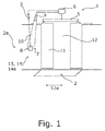
- the access control system is adapted for an access device 1 of a vehicle, wherein the access device 1 is a vehicle door 2 of a rail vehicle, of which only an interior 2a is shown here.
- the access control system comprises a sensor arrangement 3, which is specifically a laser scanner. This sensor arrangement 3 detects contact movement and especially a hand movement of a user in a spatial detection area 4.
- the access control system comprises a closing arrangement 5 which serves in a manner known per se for mechanical locking, mechanical unlocking and opening and closing of the vehicle door 2.
- the access control system comprises a processing device 6 which controls the closing arrangement 5 and which receives a signal from the sensor arrangement 3 when it has detected a user movement.
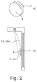
- the access control system comprises an operating body 7, which is formed by a disk-like projection and whose circular and curved front surface forms a reflection surface 8 for the diffuse scattering of incident light.
- the operating body 7 is rigid and immovable and is in the Fig. 2 shown enlarged.
- the reflection surface 8 has only one reflection region.
- the reflection surface 8 could have a plurality of reflection regions each having different reflection properties.
- the access control system comprises a projection device 9, which is a light emitter and which emits a cone of light 10 on the reflection surface 8, wherein the light of the light cone 10 is reflected by the reflection surface 8.
- the light cone 10 is colored and in this particular case illustrated green, as im in the Fig. 1 illustrated state, the access device 1 is unlocked.
- the projection device 9 can also change the color of the light cone 10 and, for example, emit a red cone of light 10.
- the light cone 10 extends in a cross-sectional projection substantially vertically downwards, wherein the schematic representation of Fig. 2b for illustration purposes deviates slightly more from this vertical course.
- the cylindrical detection area 4 is formed by a volume in front of the reflection surface 8, which is defined in front of the reflection surface 8 essentially by a maximum distance profile, which distance is presently constant. This volume adjoins the reflection surface 8 and can also be referred to as the proximity region 4a. A contact of the reflection surface 8 is thus detected as user movement by the sensor arrangement 3.
- a current access lock state of the access device 1 is maintained, which in the present case is an unlocked state as stated above. In this unlocked state, the detection of a user movement causes the vehicle door 2 to be opened by the closing arrangement 5, as shown.
- the access device 1 may also assume a locked state as an access lock state, for example, during a travel of the vehicle. Then, the projection device 9 emits a red light cone 10 and a user movement detected by the sensor arrangement 3 does not trigger opening of the vehicle door 2.
- the vehicle door 2 has a door leaf 11, with which a door opening 12 can be optionally closed or released. It can also be seen that the projection device 9 is arranged essentially above the door opening 12 with respect to a transverse direction 12 a of the vehicle, that is to say in accordance with a transverse view of the vehicle.
- This door opening 12 is located next to a vehicle wall 13, on which vehicle wall 13 of the operating body 7 is arranged.
- the vehicle wall 13 forms a flat carrier wall 14, from which the one surface of the operating body 7 is deposited, which forms the reflection surface 8.
- the support wall 14 itself in turn forms an inner surface 14a of the vehicle.
- an arrangement of the operating body 7 on the door leaf 11 would be conceivable, either on an inner side of the door leaf 11 or on an outer side of the door leaf 11. It would also be conceivable to arrange the operating body 7 with the reflection surface 8 on an outer surface of the vehicle, which outer surface is formed by the outer side of the vehicle wall 13.
Landscapes
- Engineering & Computer Science (AREA)
- Mechanical Engineering (AREA)
- Lock And Its Accessories (AREA)
- Power-Operated Mechanisms For Wings (AREA)
Priority Applications (3)
| Application Number | Priority Date | Filing Date | Title |
|---|---|---|---|
| ES16189524T ES2890661T3 (es) | 2016-09-19 | 2016-09-19 | Sistema de control de acceso para un dispositivo de acceso de un vehículo |
| PL16189524T PL3296177T3 (pl) | 2016-09-19 | 2016-09-19 | System kontroli dostępu do urządzenia dostępowego w pojeździe |
| EP16189524.8A EP3296177B1 (fr) | 2016-09-19 | 2016-09-19 | Système de contrôle d'accès à un dispositif d'accès de véhicule |
Applications Claiming Priority (1)
| Application Number | Priority Date | Filing Date | Title |
|---|---|---|---|
| EP16189524.8A EP3296177B1 (fr) | 2016-09-19 | 2016-09-19 | Système de contrôle d'accès à un dispositif d'accès de véhicule |
Publications (2)
| Publication Number | Publication Date |
|---|---|
| EP3296177A1 true EP3296177A1 (fr) | 2018-03-21 |
| EP3296177B1 EP3296177B1 (fr) | 2021-08-11 |
Family
ID=56979400
Family Applications (1)
| Application Number | Title | Priority Date | Filing Date |
|---|---|---|---|
| EP16189524.8A Active EP3296177B1 (fr) | 2016-09-19 | 2016-09-19 | Système de contrôle d'accès à un dispositif d'accès de véhicule |
Country Status (3)
| Country | Link |
|---|---|
| EP (1) | EP3296177B1 (fr) |
| ES (1) | ES2890661T3 (fr) |
| PL (1) | PL3296177T3 (fr) |
Cited By (1)
| Publication number | Priority date | Publication date | Assignee | Title |
|---|---|---|---|---|
| EP3882104A1 (fr) * | 2020-03-19 | 2021-09-22 | Knorr-Bremse Gesellschaft mit beschränkter Haftung | Bouton pour un système d'entrée pourvu d'au moins une porte pour un véhicule ferroviaire et système d'entrée pourvu d'au moins une porte et d'un bouton |
Citations (10)
| Publication number | Priority date | Publication date | Assignee | Title |
|---|---|---|---|---|
| US4621452A (en) * | 1985-01-18 | 1986-11-11 | Deeg Wyman L | Powered sliding door safety system |
| WO1995025380A1 (fr) * | 1994-03-17 | 1995-09-21 | Prospects Corporation | Systeme commande d'aeration d'un vehicule |
| DE19723974A1 (de) * | 1997-06-06 | 1998-12-17 | Draexlmaier Lisa Gmbh | Verfahren zum Verhindern des Einklemmens eines Fremdkörpers und Einklemmschutzsystem |
| US5955854A (en) * | 1992-09-29 | 1999-09-21 | Prospects Corporation | Power driven venting of a vehicle |
| EP1011184A1 (fr) * | 1998-12-15 | 2000-06-21 | Talltec Technologies Holdings S.A. | Dispositif de sécurité associé à un panneau coulissant entraíné par un moteur électrique et procédé de mise en oeuvre d'un tel dispositif |
| WO2006072617A2 (fr) * | 2005-01-10 | 2006-07-13 | Siemens Aktiengesellschaft | Systeme pour controler la zone entre un train et le bord d'une plateforme |
| DE202005011480U1 (de) * | 2005-07-21 | 2006-12-14 | Brose Fahrzeugteile Gmbh & Co. Kommanditgesellschaft, Coburg | Karosserieteil |
| DE102007001178A1 (de) * | 2007-01-05 | 2008-07-10 | Siemens Ag | Berührungsloser Einklemmschutz |
| DE102014113567A1 (de) | 2014-09-19 | 2016-03-24 | Gebr. Bode Gmbh & Co. Kg | Türsystem mit Sensoreinheit zur berührungslosen Fahrgastraumüberwachung |
| DE102014113569A1 (de) * | 2014-09-19 | 2016-03-24 | Gebr. Bode Gmbh & Co. Kg | Türsystem mit Sensoreinheit und Kommunikationselement |
-
2016
- 2016-09-19 EP EP16189524.8A patent/EP3296177B1/fr active Active
- 2016-09-19 PL PL16189524T patent/PL3296177T3/pl unknown
- 2016-09-19 ES ES16189524T patent/ES2890661T3/es active Active
Patent Citations (10)
| Publication number | Priority date | Publication date | Assignee | Title |
|---|---|---|---|---|
| US4621452A (en) * | 1985-01-18 | 1986-11-11 | Deeg Wyman L | Powered sliding door safety system |
| US5955854A (en) * | 1992-09-29 | 1999-09-21 | Prospects Corporation | Power driven venting of a vehicle |
| WO1995025380A1 (fr) * | 1994-03-17 | 1995-09-21 | Prospects Corporation | Systeme commande d'aeration d'un vehicule |
| DE19723974A1 (de) * | 1997-06-06 | 1998-12-17 | Draexlmaier Lisa Gmbh | Verfahren zum Verhindern des Einklemmens eines Fremdkörpers und Einklemmschutzsystem |
| EP1011184A1 (fr) * | 1998-12-15 | 2000-06-21 | Talltec Technologies Holdings S.A. | Dispositif de sécurité associé à un panneau coulissant entraíné par un moteur électrique et procédé de mise en oeuvre d'un tel dispositif |
| WO2006072617A2 (fr) * | 2005-01-10 | 2006-07-13 | Siemens Aktiengesellschaft | Systeme pour controler la zone entre un train et le bord d'une plateforme |
| DE202005011480U1 (de) * | 2005-07-21 | 2006-12-14 | Brose Fahrzeugteile Gmbh & Co. Kommanditgesellschaft, Coburg | Karosserieteil |
| DE102007001178A1 (de) * | 2007-01-05 | 2008-07-10 | Siemens Ag | Berührungsloser Einklemmschutz |
| DE102014113567A1 (de) | 2014-09-19 | 2016-03-24 | Gebr. Bode Gmbh & Co. Kg | Türsystem mit Sensoreinheit zur berührungslosen Fahrgastraumüberwachung |
| DE102014113569A1 (de) * | 2014-09-19 | 2016-03-24 | Gebr. Bode Gmbh & Co. Kg | Türsystem mit Sensoreinheit und Kommunikationselement |
Cited By (2)
| Publication number | Priority date | Publication date | Assignee | Title |
|---|---|---|---|---|
| EP3882104A1 (fr) * | 2020-03-19 | 2021-09-22 | Knorr-Bremse Gesellschaft mit beschränkter Haftung | Bouton pour un système d'entrée pourvu d'au moins une porte pour un véhicule ferroviaire et système d'entrée pourvu d'au moins une porte et d'un bouton |
| WO2021185908A1 (fr) * | 2020-03-19 | 2021-09-23 | Knorr-Bremse Gesellschaft Mit Beschränkter Haftung | Unité de bouton pour système d'entrée doté d'au moins une porte pour véhicule ferroviaire, et système d'entrée doté présentant au moins une porte et une unité de bouton |
Also Published As
| Publication number | Publication date |
|---|---|
| PL3296177T3 (pl) | 2022-01-03 |
| ES2890661T3 (es) | 2022-01-21 |
| EP3296177B1 (fr) | 2021-08-11 |
Similar Documents
| Publication | Publication Date | Title |
|---|---|---|
| EP3099547B1 (fr) | Module prêt au montage | |
| DE102016211494B4 (de) | Steuerungseinrichtung für ein Kraftfahrzeug | |
| EP2844528B1 (fr) | Procédé d'actionnement d'un ensemble élément de fermeture d'un véhicule automobile | |
| EP3194241B1 (fr) | Système de porte comprenant une unité de détection et un élément de communication | |
| DE102016216415B4 (de) | Verfahren zum Steuern einer Anzeigevorrichtung für ein Kraftfahrzeug und Kraftfahrzeug mit einer Anzeigevorrichtung | |
| DE102013009673A1 (de) | Kollisionsschutzverfahren und Kollisionsschutzvorrichtung für ein verstellbares Fahrzeugteil | |
| DE102012108004A1 (de) | Sicherheitssystem für eine Kraftfahrzeugtür eines Kraftfahrzeuges mit mindestens zwei Sensoren | |
| DE102010056171A1 (de) | Verfahren zum automatischen Betätigen eines Schließelements eines Fahrzeugs sowie entsprechende Vorrichtung und Fahrzeug | |
| DE102016211495A1 (de) | Steuerungseinrichtung für ein Kraftfahrzeug | |
| EP2038503B1 (fr) | Dispositif de blocage d'accès | |
| DE102014222410B4 (de) | Zugangssystem für ein Fahrzeug | |
| DE202010006996U1 (de) | Verriegelungssystem für eine Kraftfahrzeugtür | |
| DE102014001321A1 (de) | Verfahren zum Betrieb mindestens eines Bedienelements für eine Fahrzeugtür eines Kraftfahrzeugs und Kraftfahrzeug | |
| EP3296177A1 (fr) | Système de contrôle d'accès à un dispositif d'accès de véhicule | |
| DE102022104046A1 (de) | Fahrzeugtür für einen Kraftwagen sowie Verfahren zum Betreiben einer solchen Fahrzeugtür | |
| DE102016002778A1 (de) | Belüftungseinrichtung für einen Innenraum eines Kraftfahrzeugs | |
| EP2974938A1 (fr) | Dispositif et procede de positionnement d'un dispositif d'aide et vehicule sur rails | |
| WO2024002624A1 (fr) | Poignée de porte extérieure destinée à être fixée à une porte latérale ou à un véhicule à moteur | |
| EP1273494B1 (fr) | Dispositif de surveillance pour l'intérieur de véhicule | |
| DE102022119083A1 (de) | Verkleidungsanordnung für einen mit einem Stauraum ausgestatteten Vorder- oder Hinterwagen eines Personenkraftwagens | |
| DE102018005464B4 (de) | Fahrzeugtür oder -klappe und Verfahren zum Betreiben einer Fahrzeugtür oder -klappe | |
| DE102022105504A1 (de) | Modulbauteil für ein bewegliches Teil eines Fahrzeuges und ein Verfahren zum Herstellen eines Modulbauteils | |
| DE102022104044A1 (de) | Fahrzeugtür für einen Kraftwagen sowie Verfahren zum Betreiben einer solchen Fahrzeugtür | |
| DE202016106557U1 (de) | Fahrzeug mit einer Wandleranordnung | |
| DE102011002054A1 (de) | Flügelanlage |
Legal Events
| Date | Code | Title | Description |
|---|---|---|---|
| PUAI | Public reference made under article 153(3) epc to a published international application that has entered the european phase |
Free format text: ORIGINAL CODE: 0009012 |
|
| STAA | Information on the status of an ep patent application or granted ep patent |
Free format text: STATUS: THE APPLICATION HAS BEEN PUBLISHED |
|
| AK | Designated contracting states |
Kind code of ref document: A1 Designated state(s): AL AT BE BG CH CY CZ DE DK EE ES FI FR GB GR HR HU IE IS IT LI LT LU LV MC MK MT NL NO PL PT RO RS SE SI SK SM TR |
|
| AX | Request for extension of the european patent |
Extension state: BA ME |
|
| STAA | Information on the status of an ep patent application or granted ep patent |
Free format text: STATUS: REQUEST FOR EXAMINATION WAS MADE |
|
| 17P | Request for examination filed |
Effective date: 20180921 |
|
| RBV | Designated contracting states (corrected) |
Designated state(s): AL AT BE BG CH CY CZ DE DK EE ES FI FR GB GR HR HU IE IS IT LI LT LU LV MC MK MT NL NO PL PT RO RS SE SI SK SM TR |
|
| GRAP | Despatch of communication of intention to grant a patent |
Free format text: ORIGINAL CODE: EPIDOSNIGR1 |
|
| STAA | Information on the status of an ep patent application or granted ep patent |
Free format text: STATUS: GRANT OF PATENT IS INTENDED |
|
| INTG | Intention to grant announced |
Effective date: 20210322 |
|
| GRAS | Grant fee paid |
Free format text: ORIGINAL CODE: EPIDOSNIGR3 |
|
| GRAA | (expected) grant |
Free format text: ORIGINAL CODE: 0009210 |
|
| STAA | Information on the status of an ep patent application or granted ep patent |
Free format text: STATUS: THE PATENT HAS BEEN GRANTED |
|
| AK | Designated contracting states |
Kind code of ref document: B1 Designated state(s): AL AT BE BG CH CY CZ DE DK EE ES FI FR GB GR HR HU IE IS IT LI LT LU LV MC MK MT NL NO PL PT RO RS SE SI SK SM TR |
|
| REG | Reference to a national code |
Ref country code: CH Ref legal event code: EP |
|
| REG | Reference to a national code |
Ref country code: DE Ref legal event code: R096 Ref document number: 502016013585 Country of ref document: DE |
|
| REG | Reference to a national code |
Ref country code: IE Ref legal event code: FG4D Free format text: LANGUAGE OF EP DOCUMENT: GERMAN Ref country code: AT Ref legal event code: REF Ref document number: 1419116 Country of ref document: AT Kind code of ref document: T Effective date: 20210915 |
|
| REG | Reference to a national code |
Ref country code: NL Ref legal event code: FP |
|
| REG | Reference to a national code |
Ref country code: LT Ref legal event code: MG9D |
|
| REG | Reference to a national code |
Ref country code: ES Ref legal event code: FG2A Ref document number: 2890661 Country of ref document: ES Kind code of ref document: T3 Effective date: 20220121 |
|
| PG25 | Lapsed in a contracting state [announced via postgrant information from national office to epo] |
Ref country code: RS Free format text: LAPSE BECAUSE OF FAILURE TO SUBMIT A TRANSLATION OF THE DESCRIPTION OR TO PAY THE FEE WITHIN THE PRESCRIBED TIME-LIMIT Effective date: 20210811 Ref country code: SE Free format text: LAPSE BECAUSE OF FAILURE TO SUBMIT A TRANSLATION OF THE DESCRIPTION OR TO PAY THE FEE WITHIN THE PRESCRIBED TIME-LIMIT Effective date: 20210811 Ref country code: HR Free format text: LAPSE BECAUSE OF FAILURE TO SUBMIT A TRANSLATION OF THE DESCRIPTION OR TO PAY THE FEE WITHIN THE PRESCRIBED TIME-LIMIT Effective date: 20210811 Ref country code: PT Free format text: LAPSE BECAUSE OF FAILURE TO SUBMIT A TRANSLATION OF THE DESCRIPTION OR TO PAY THE FEE WITHIN THE PRESCRIBED TIME-LIMIT Effective date: 20211213 Ref country code: NO Free format text: LAPSE BECAUSE OF FAILURE TO SUBMIT A TRANSLATION OF THE DESCRIPTION OR TO PAY THE FEE WITHIN THE PRESCRIBED TIME-LIMIT Effective date: 20211111 Ref country code: FI Free format text: LAPSE BECAUSE OF FAILURE TO SUBMIT A TRANSLATION OF THE DESCRIPTION OR TO PAY THE FEE WITHIN THE PRESCRIBED TIME-LIMIT Effective date: 20210811 Ref country code: LT Free format text: LAPSE BECAUSE OF FAILURE TO SUBMIT A TRANSLATION OF THE DESCRIPTION OR TO PAY THE FEE WITHIN THE PRESCRIBED TIME-LIMIT Effective date: 20210811 Ref country code: BG Free format text: LAPSE BECAUSE OF FAILURE TO SUBMIT A TRANSLATION OF THE DESCRIPTION OR TO PAY THE FEE WITHIN THE PRESCRIBED TIME-LIMIT Effective date: 20211111 |
|
| REG | Reference to a national code |
Ref country code: DE Ref legal event code: R081 Ref document number: 502016013585 Country of ref document: DE Owner name: BODE - DIE TUER GMBH, DE Free format text: FORMER OWNER: GEBR. BODE GMBH & CO. KG, 34123 KASSEL, DE |
|
| PG25 | Lapsed in a contracting state [announced via postgrant information from national office to epo] |
Ref country code: LV Free format text: LAPSE BECAUSE OF FAILURE TO SUBMIT A TRANSLATION OF THE DESCRIPTION OR TO PAY THE FEE WITHIN THE PRESCRIBED TIME-LIMIT Effective date: 20210811 Ref country code: GR Free format text: LAPSE BECAUSE OF FAILURE TO SUBMIT A TRANSLATION OF THE DESCRIPTION OR TO PAY THE FEE WITHIN THE PRESCRIBED TIME-LIMIT Effective date: 20211112 |
|
| PG25 | Lapsed in a contracting state [announced via postgrant information from national office to epo] |
Ref country code: DK Free format text: LAPSE BECAUSE OF FAILURE TO SUBMIT A TRANSLATION OF THE DESCRIPTION OR TO PAY THE FEE WITHIN THE PRESCRIBED TIME-LIMIT Effective date: 20210811 |
|
| REG | Reference to a national code |
Ref country code: DE Ref legal event code: R097 Ref document number: 502016013585 Country of ref document: DE |
|
| REG | Reference to a national code |
Ref country code: BE Ref legal event code: MM Effective date: 20210930 |
|
| PG25 | Lapsed in a contracting state [announced via postgrant information from national office to epo] |
Ref country code: SM Free format text: LAPSE BECAUSE OF FAILURE TO SUBMIT A TRANSLATION OF THE DESCRIPTION OR TO PAY THE FEE WITHIN THE PRESCRIBED TIME-LIMIT Effective date: 20210811 Ref country code: SK Free format text: LAPSE BECAUSE OF FAILURE TO SUBMIT A TRANSLATION OF THE DESCRIPTION OR TO PAY THE FEE WITHIN THE PRESCRIBED TIME-LIMIT Effective date: 20210811 Ref country code: RO Free format text: LAPSE BECAUSE OF FAILURE TO SUBMIT A TRANSLATION OF THE DESCRIPTION OR TO PAY THE FEE WITHIN THE PRESCRIBED TIME-LIMIT Effective date: 20210811 Ref country code: MC Free format text: LAPSE BECAUSE OF FAILURE TO SUBMIT A TRANSLATION OF THE DESCRIPTION OR TO PAY THE FEE WITHIN THE PRESCRIBED TIME-LIMIT Effective date: 20210811 Ref country code: EE Free format text: LAPSE BECAUSE OF FAILURE TO SUBMIT A TRANSLATION OF THE DESCRIPTION OR TO PAY THE FEE WITHIN THE PRESCRIBED TIME-LIMIT Effective date: 20210811 Ref country code: AL Free format text: LAPSE BECAUSE OF FAILURE TO SUBMIT A TRANSLATION OF THE DESCRIPTION OR TO PAY THE FEE WITHIN THE PRESCRIBED TIME-LIMIT Effective date: 20210811 |
|
| PLBE | No opposition filed within time limit |
Free format text: ORIGINAL CODE: 0009261 |
|
| STAA | Information on the status of an ep patent application or granted ep patent |
Free format text: STATUS: NO OPPOSITION FILED WITHIN TIME LIMIT |
|
| 26N | No opposition filed |
Effective date: 20220512 |
|
| PG25 | Lapsed in a contracting state [announced via postgrant information from national office to epo] |
Ref country code: LU Free format text: LAPSE BECAUSE OF NON-PAYMENT OF DUE FEES Effective date: 20210919 Ref country code: IE Free format text: LAPSE BECAUSE OF NON-PAYMENT OF DUE FEES Effective date: 20210919 Ref country code: BE Free format text: LAPSE BECAUSE OF NON-PAYMENT OF DUE FEES Effective date: 20210930 |
|
| PG25 | Lapsed in a contracting state [announced via postgrant information from national office to epo] |
Ref country code: SI Free format text: LAPSE BECAUSE OF FAILURE TO SUBMIT A TRANSLATION OF THE DESCRIPTION OR TO PAY THE FEE WITHIN THE PRESCRIBED TIME-LIMIT Effective date: 20210811 |
|
| PG25 | Lapsed in a contracting state [announced via postgrant information from national office to epo] |
Ref country code: HU Free format text: LAPSE BECAUSE OF FAILURE TO SUBMIT A TRANSLATION OF THE DESCRIPTION OR TO PAY THE FEE WITHIN THE PRESCRIBED TIME-LIMIT; INVALID AB INITIO Effective date: 20160919 |
|
| PG25 | Lapsed in a contracting state [announced via postgrant information from national office to epo] |
Ref country code: CY Free format text: LAPSE BECAUSE OF FAILURE TO SUBMIT A TRANSLATION OF THE DESCRIPTION OR TO PAY THE FEE WITHIN THE PRESCRIBED TIME-LIMIT Effective date: 20210811 |
|
| PG25 | Lapsed in a contracting state [announced via postgrant information from national office to epo] |
Ref country code: MK Free format text: LAPSE BECAUSE OF FAILURE TO SUBMIT A TRANSLATION OF THE DESCRIPTION OR TO PAY THE FEE WITHIN THE PRESCRIBED TIME-LIMIT Effective date: 20210811 |
|
| PG25 | Lapsed in a contracting state [announced via postgrant information from national office to epo] |
Ref country code: MT Free format text: LAPSE BECAUSE OF FAILURE TO SUBMIT A TRANSLATION OF THE DESCRIPTION OR TO PAY THE FEE WITHIN THE PRESCRIBED TIME-LIMIT Effective date: 20210811 |
|
| PGFP | Annual fee paid to national office [announced via postgrant information from national office to epo] |
Ref country code: DE Payment date: 20240919 Year of fee payment: 9 |
|
| PGFP | Annual fee paid to national office [announced via postgrant information from national office to epo] |
Ref country code: GB Payment date: 20240923 Year of fee payment: 9 |
|
| PGFP | Annual fee paid to national office [announced via postgrant information from national office to epo] |
Ref country code: FR Payment date: 20240924 Year of fee payment: 9 |
|
| PGFP | Annual fee paid to national office [announced via postgrant information from national office to epo] |
Ref country code: NL Payment date: 20240920 Year of fee payment: 9 |
|
| PGFP | Annual fee paid to national office [announced via postgrant information from national office to epo] |
Ref country code: CZ Payment date: 20240910 Year of fee payment: 9 |
|
| PGFP | Annual fee paid to national office [announced via postgrant information from national office to epo] |
Ref country code: AT Payment date: 20240918 Year of fee payment: 9 |
|
| PGFP | Annual fee paid to national office [announced via postgrant information from national office to epo] |
Ref country code: PL Payment date: 20240910 Year of fee payment: 9 |
|
| PGFP | Annual fee paid to national office [announced via postgrant information from national office to epo] |
Ref country code: TR Payment date: 20240911 Year of fee payment: 9 |
|
| PGFP | Annual fee paid to national office [announced via postgrant information from national office to epo] |
Ref country code: IT Payment date: 20240930 Year of fee payment: 9 Ref country code: ES Payment date: 20241018 Year of fee payment: 9 |
|
| PGFP | Annual fee paid to national office [announced via postgrant information from national office to epo] |
Ref country code: CH Payment date: 20241001 Year of fee payment: 9 |