EP0573388A1 - Einrichtung zur Erzeugung charakteristischer Signale der Verschiebung eines Verschlussmittels - Google Patents
Einrichtung zur Erzeugung charakteristischer Signale der Verschiebung eines Verschlussmittels Download PDFInfo
- Publication number
- EP0573388A1 EP0573388A1 EP93810369A EP93810369A EP0573388A1 EP 0573388 A1 EP0573388 A1 EP 0573388A1 EP 93810369 A EP93810369 A EP 93810369A EP 93810369 A EP93810369 A EP 93810369A EP 0573388 A1 EP0573388 A1 EP 0573388A1
- Authority
- EP
- European Patent Office
- Prior art keywords
- signal
- closure
- wiper
- movement
- subroutine
- Prior art date
- Legal status (The legal status is an assumption and is not a legal conclusion. Google has not performed a legal analysis and makes no representation as to the accuracy of the status listed.)
- Granted
Links
Images


Classifications
-
- E—FIXED CONSTRUCTIONS
- E06—DOORS, WINDOWS, SHUTTERS, OR ROLLER BLINDS IN GENERAL; LADDERS
- E06B—FIXED OR MOVABLE CLOSURES FOR OPENINGS IN BUILDINGS, VEHICLES, FENCES OR LIKE ENCLOSURES IN GENERAL, e.g. DOORS, WINDOWS, BLINDS, GATES
- E06B9/00—Screening or protective devices for wall or similar openings, with or without operating or securing mechanisms; Closures of similar construction
- E06B9/56—Operating, guiding or securing devices or arrangements for roll-type closures; Spring drums; Tape drums; Counterweighting arrangements therefor
- E06B9/80—Safety measures against dropping or unauthorised opening; Braking or immobilising devices; Devices for limiting unrolling
- E06B9/82—Safety measures against dropping or unauthorised opening; Braking or immobilising devices; Devices for limiting unrolling automatic
- E06B9/86—Safety measures against dropping or unauthorised opening; Braking or immobilising devices; Devices for limiting unrolling automatic against unauthorised opening
-
- E—FIXED CONSTRUCTIONS
- E06—DOORS, WINDOWS, SHUTTERS, OR ROLLER BLINDS IN GENERAL; LADDERS
- E06B—FIXED OR MOVABLE CLOSURES FOR OPENINGS IN BUILDINGS, VEHICLES, FENCES OR LIKE ENCLOSURES IN GENERAL, e.g. DOORS, WINDOWS, BLINDS, GATES
- E06B9/00—Screening or protective devices for wall or similar openings, with or without operating or securing mechanisms; Closures of similar construction
- E06B9/56—Operating, guiding or securing devices or arrangements for roll-type closures; Spring drums; Tape drums; Counterweighting arrangements therefor
- E06B9/80—Safety measures against dropping or unauthorised opening; Braking or immobilising devices; Devices for limiting unrolling
- E06B9/82—Safety measures against dropping or unauthorised opening; Braking or immobilising devices; Devices for limiting unrolling automatic
- E06B9/88—Safety measures against dropping or unauthorised opening; Braking or immobilising devices; Devices for limiting unrolling automatic for limiting unrolling
-
- E—FIXED CONSTRUCTIONS
- E06—DOORS, WINDOWS, SHUTTERS, OR ROLLER BLINDS IN GENERAL; LADDERS
- E06B—FIXED OR MOVABLE CLOSURES FOR OPENINGS IN BUILDINGS, VEHICLES, FENCES OR LIKE ENCLOSURES IN GENERAL, e.g. DOORS, WINDOWS, BLINDS, GATES
- E06B9/00—Screening or protective devices for wall or similar openings, with or without operating or securing mechanisms; Closures of similar construction
- E06B9/56—Operating, guiding or securing devices or arrangements for roll-type closures; Spring drums; Tape drums; Counterweighting arrangements therefor
- E06B9/68—Operating devices or mechanisms, e.g. with electric drive
- E06B2009/6809—Control
- E06B2009/6818—Control using sensors
- E06B2009/6836—Control using sensors sensing obstacle
-
- E—FIXED CONSTRUCTIONS
- E06—DOORS, WINDOWS, SHUTTERS, OR ROLLER BLINDS IN GENERAL; LADDERS
- E06B—FIXED OR MOVABLE CLOSURES FOR OPENINGS IN BUILDINGS, VEHICLES, FENCES OR LIKE ENCLOSURES IN GENERAL, e.g. DOORS, WINDOWS, BLINDS, GATES
- E06B9/00—Screening or protective devices for wall or similar openings, with or without operating or securing mechanisms; Closures of similar construction
- E06B9/56—Operating, guiding or securing devices or arrangements for roll-type closures; Spring drums; Tape drums; Counterweighting arrangements therefor
- E06B9/68—Operating devices or mechanisms, e.g. with electric drive
- E06B2009/6809—Control
- E06B2009/6818—Control using sensors
- E06B2009/6845—Control using sensors sensing position
Definitions
- the present invention relates to a device generating signals characteristic of the movement of a closure means, such as a shutter, rollable or not, blind or door.
- Such generators are used for commanding and controlling the movement of closing means, in particular for detecting obstacles, detecting intrusion attempts and controlling the stopping of the closing means at the end of the travel.
- a signal generator device associated with a motorized roller shutter is described in patent FR 2 657 646.
- This generator comprises a pulley mounted on the winding axis of the roller shutter and on which is wound a flexible element whose other end is connected to the end of the roller shutter, so that the unwinding of the shutter drives the pulley, the axis of which is mechanically connected to a signal generator, for example a synchronous motor.
- the generator arranged laterally on the winding axis, therefore requires a space which is not always available in a window frame or a door frame.
- the flexible element connecting the generator pulley to the final bar of the roller shutter is unattractive and this flexible element may be accidentally hung or damaged due to its unprotected passage, such an incident being liable to seriously disturb the operation of the roller shutter.
- the present invention aims to overcome these drawbacks.
- the signal generator device is characterized in that it comprises a wiper secured to the closure means, a fixed rigid element capable of being driven in vibration by the wiper and extending over at least the length of the stroke of the closure means so that the wiper rubs on the rigid element during the displacement of the closure means, and a vibration sensor rigidly mounted on the rigid element and delivering a signal characteristic of these vibrations.
- the closing means generally comprise guide means in the form of a slide, so that the wiper can move in the slide while being hidden and perfectly protected.
- the rigid vibrating element can be constituted by the slide itself or by the guide slide of a tilting or side-moving door or by an element attached to this slide or this slide.
- the invention also relates to a motorized closure equipped with at least one signal generator device according to the invention, this closure being characterized in that it further comprises electronic means for processing the signal emitted by the vibration sensor and means for controlling the motor or motors for driving the closing means as a function of the orders received from the signal processing means.
- the control means can ensure both the closure stop, when the latter encounters an obstacle, as well as the triggering of an alarm in the event of an attempt intrusion, as well as the closure stop at the end of the race and / or in intermediate positions, using a toothed or grooved vibrating element allowing to obtain a vibration having periodic variations corresponding to its teeth or grooves and therefore characteristics of the closing position.
- Figure 1 is a sectional view of a roller shutter equipped with a generator according to the invention.
- Figure 2 shows a detail of Figure 1.
- FIG. 3 represents an alternative embodiment of FIG. 2.
- Figure 4 shows the detail, in vertical section along IV-IV of Figure 5, of an exemplary embodiment of the vibrating element and the wiper.
- FIG. 5 is a sectional view along V-V of FIG. 4.
- FIGS 6 and 7 show two other embodiments of the vibrating element.
- FIG. 8 represents the diagram of the signal processing means and of the means for controlling the rolling stock shown in FIG. 1.
- FIG. 9 represents a first embodiment of the reference signal generator.
- FIG. 10 represents a simplified embodiment of the reference signal generator.
- FIG. 11 represents the main program of the control means.
- FIG. 12 shows a variant of a sub-program for controlling the shutter to stop.
- FIG. 13 represents a variant of the subroutine for triggering an alarm in the event of an intrusion attempt.
- FIG. 14 represents the decoding circuit of an alternative embodiment with two sensors.
- FIG. 15 represents the diagram of a wired execution of the control device.
- FIG. 16 represents a variant of the main program for the case of transmission of signals with periodic variations.
- Figure 17 shows the variation counting routine.
- Figure 18 shows the alarm routine.
- FIG. 19 represents a modification of the program of FIG. 16 making it possible to obtain intermediate stop positions.
- FIG. 20 represents the counting subroutine of the variant represented in FIG. 19.
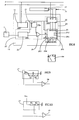
- Figure 1 shows, in vertical section, a window frame 1 in which is mounted a rolling shutter 2 guided in a pair of runners 3 and winding on a winding axis 4 mounted in a housing 5 and driven by a motor not shown.
- the motor has two windings ensuring the rotation of the winding shaft 4 in two opposite directions.
- the roller shutter 2 is shown here in the fully unrolled position. Its last blade is provided with an end of travel stop 6 constituted by a lug intended to come into abutment against the top of the embrasure 1.
- the slide 3 is extended by a part 3a in the housing 5 and at the end of this extension 3a is rigidly fixed a vibration sensor 7.
- On the last blade 8 of the roller shutter is further fixed a wiper, for example a steel blade whose free end rubs on one of the inner faces of the slide whose the surface has been roughened or grainy by sandblasting.
- the vibration sensor can be of the accelerometer or piezoelectric or ferroelectric shock detector type, of micro-machined silicon with integrated processing electronics, for example a sensor sold by MURATA under the trade name PKS-4A.
- the signals emitted by the sensor 7 are processed by a control device 13 controlling the motor of the winding axis 4.
- the installation is completed by a remote control 14, connected galvanically or not to the control electronics 13 and comprising keys for controlling the raising, lowering and stopping of the shutter.
- the wiper can rub on an auxiliary vibrating element.
- the vibrating element consists of a steel blade 9 fixed on one of the inner faces 10 of the slide 3 and on which a wiper 11 rubs
- the opposite face 12 of the slide is smooth and the last blade 8 is provided with a shoe 15 sliding on the face 12.
- the stop 6 abuts against the embrasure when the shutter arrives at high position, the vibrations cease and the detector 7 detects the absence of vibration and controls the stopping of the engine.
- FIG 3 shows an alternative embodiment of Figure 2, in which the stop 6 is removed and the vibrating element 9 is shorter.
- the upper position of the shutter is reached when the wiper leaves the vibrating element 9. This execution allows the shutter to stop smoothly, without sudden pulling. She is particularly advantageous in the case of fragile roller shutters.
- FIGS 4 and 5 show, in more detail, an embodiment and mounting of the wiper 11. It is fixed by riveting, welding or clipping at a point 17 inside the last tubular blade 8 of the shutter rolling and passes through this blade through a slot 18.
- the wiper 11 has a curved end 11a in contact with the vibrating element formed here by the slide 3 itself.
- the vibrating element consists of a rough blade 19 fixed to the slide by means of an adhesive 20.
- the rough blade 19 is replaced by a blade 21 having a serrated profile 22.
- This profile could also be serrated.
- Such a profile makes it possible to obtain a periodic variation in the amplitude of the vibrations, each variation corresponding to a tooth or a niche.
- the counting of these variations makes it possible to determine the position of the wiper, that is to say the position of the roller shutter.
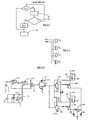
- the control device 13 is shown diagrammatically in FIG. 8. It consists of processing electronics 23 and control electronics 24 for controlling the motor 25.
- the processing electronics include an amplifier-demodulator 26, a reference generator 27 and a comparator 28.
- the function of the amplifier-demodulator 26 is to receive the signal delivered by the sensor, to amplify it, possibly to rectify it, to smooth it out and to deliver to the comparator 28 to which is applied, on the other hand, a reference value delivered by the reference generator 27.
- the reference generator 27 can be constituted by a simple voltage divider R1 / R2, as shown in FIG. 10, delivering a fixed voltage value.
- the reference generator 27 can also be designed to deliver a reference value derived from the value of the signal picked up, as shown in FIG. 9. In this case, it consists of a voltage divider R1 / R2 in parallel to a capacitor C, all in series with a resistor R3 to which the sensed signal is applied. This allows to take into account the variation of the signal received due to the aging of the sensor or to any other influence and to automatically adapt to the signal level corresponding to the use.
- the function of the comparator 28 is to compare the value of the signal received from the amplifier-demodulator 26 with that received from the reference generator 27 and to deliver a logic signal (0 or 1) according to the relative level of the compared values. In the particular case, the comparator 28 delivers the signal 1 when the value of the sensed signal is greater than the reference value.
- the microprocessor 29 further comprises a fourth DPI input (intermediate position request), a position counter 291 and a reaction time counter 292, a memory 294 for storing the alarm reaction time or the minimum position variation for triggering an alarm and a memory 295 for storing the value of the position counter.
- a fourth DPI input intermediate position request
- a position counter 291 for storing the alarm reaction time or the minimum position variation for triggering an alarm
- a memory 295 for storing the value of the position counter.
- the control device 13 further comprises a stabilized supply 32 for supplying different components.
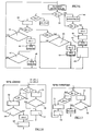
- the execution mode corresponding to the program represented in FIG. 11 includes two end of travel or obstacle indicators, up and down FCM and FCD positioned high by the stop subroutines, respectively in the direction of ascent (M) and descent (D) and reset to zero when moving in the opposite direction.
- This embodiment therefore makes it possible to stop at the end of the race at a high, low stopping point and in the event of obstacles, by detection of the interruption of the vibrations, as well as the detection of an intrusion attempt by appearance. vibrations.
- the alarm subroutine could be deleted.
- control electronics 24 is also provided for testing that the change of the logic order on the output SL of the comparator remains a certain time before suspending the transmission of direction 1 movement orders. / sense 2 or before transmitting an alarm command.
- the Up and Down stop subroutines of figure 11 are replaced by the subroutine according to figure 12 and the microprocessor includes a memory 293 storing the stop reaction time value and a stop reaction time counter 292.
- the instruction 33 increments the stop reaction time counter 292.
- the following instruction is a test instruction 34 which compares the counted value with the stored value. If the counted value is greater than the memorized value, then only the SM and SD outputs are set to zero by the following instruction and the program loops. At the same time, instruction 35 resets counter 292 to 0.
- the program loops without issuing a stop command.
- the alarm subroutine of FIG. 11 is also completed as shown in FIG. 13, in a similar manner to the shutdown subroutine of FIG. 12.
- the microprocessor includes a memory 294 storing the value of reaction time d 'alarm.
- instruction 36 increments counter 292 and instruction 37 compares the counted value with the value stored in memory 294. If the counted value is greater than the stored value, the SA output goes to 1 and a alarm is triggered. Simultaneously, instruction 38 resets the counter to 292 at 0.
- This embodiment makes it possible to avoid stopping or triggering alarms resulting from false faults, such as those caused by shocks, hard points in the slide, fugitive obstacles.
- the safety-stop device which has just been described leads to stopping the descent in the non-stacked blade position (so-called "openwork” position if the wiper has been arranged on the lower blade of the closure (blade 8).
- a second wiper should be placed on the blade penetrating the slide 3, in contact with the vibration element, just before the low blade arrives. stop. This variant does not require any modification of the algorithms and the sensor.
- Another interesting embodiment consists in using two vibration sensors, one per slide. This embodiment makes it possible to define an intermediate position and / or several operating zones.
- the intermediate position here corresponds to the "openwork" position described above.
- a first wiper A is disposed on the lower blade 8 of the shutter, on the side of a first slide 3A (or of the corresponding vibration element).
- the second wiper B is placed on the side of the slide 3B (or of the corresponding vibration element) and it is placed on the blade penetrating the slide 3B (or coming into contact with the corresponding vibration element) when the flap arrives in the intermediate position.
- FIG. 14 represents the decoding of the four usable zones.
- SLA and SLB represent the signals delivered by each of the sensors in the presence of vibrations. The algorithms for exploiting this information are within the reach of those skilled in the art.
- FIG. 15 represents a particularly simple embodiment of the logic of the control device 13 indicated by the control algorithms of FIGS. 11 and 12 (alarm function excluded).
- This embodiment uses wired logic and does not require three current integrated circuits (for example TL 084, MC 14538 B, 74 C 74) possibly replaceable by a single circuit of the ASIC type.
- a unipolar established power supply 71 supplies a supply voltage + Vcc to the entire assembly. This voltage is divided by two to allow, at the output of a follower 72, a potential reference used as virtual ground for the analog part of the circuit.
- the piezoelectric detector 7 sees its output signal amplified by two operational amplifiers 74 and 75, with elimination of any continuous components.
- the amplified signal is applied to the input (+) of an operational amplifier 76 which is used in comparator mode.
- comparator 76 corresponds to the saturation voltages of the operational amplifier and are close enough to + Vcc and 0 to attack CMOS type logic.
- Each detected and amplified vibration causes the output of comparator 76 (equivalent to the signal SL of the programmed execution) to go to the "high" state as long as the amplified level is greater than a reference voltage applied to the input ( -) of comparator 76 by a resistive divider bridge.
- Amplifiers 72, 73, 74, 75, 76 belong to the same integrated circuit (for example TL084).
- the output of comparator 76 is applied to a monostable 77 (retriggerable one shot, for example MC 14538 B) whose output Q * goes to the low state for a fixed duration T when the input A undergoes a transition from the "low” state to the "high” state.
- This duration T is always counted from the last upward transition of the input if several pulses are applied to it.
- the duration T is chosen so as to be greater than the maximum time separating two pulses during the movement of the wiper on the vibration element.
- the output Q * therefore returns to the high state only if the vibrations disappear for a duration greater than T.
- two flip-flops 78 and 79 record the state present on the Data input. This state is taken from the collectors of two transistors 80 and 81. One or the other of the transistors is conductive in the event of movement. In the Up SM direction, the transistor 80 is conductive. In the SD down direction, transistor 81 is conductive. The collector of the conducting transistor is in the "low” state while the collector of the blocked transistor is in the "high” state.
- the flip-flop 78 or 79 therefore records a "low” state on its output Q * if the vibration ceases while the direction SM or SD is activated.
- This blocked state is maintained as long as the other transistor has not been made conductive, therefore until the user has given an order of movement in the opposite direction.
- the circuit further comprises a switch 84 with three positions: DD, STOP (intermediate position) and DM controlled by the remote control 14.
- transil diodes 85 and 86 designate transil diodes or other protection devices intended to avoid induced potential variations of high amplitude on the emitter of a transistor not connected to ground by the switch 84.
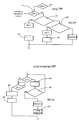
- the senor 7 is designed to emit at least one signal of higher value on the passage of each tooth or slot and the reference value supplied by the reference generator 27 of the processing electronics 23 is fixed so as to that the processing electronics does not deliver a 0 or 1 signal on the SL output until each reception of this higher value signal.
- These signals are counted by the position counter 291 of the microprocessor 29 and the number of signals transmitted is stored in memory 295.
- the program according to FIG. 16 includes the following instructions: a request and initialization (DI) instruction 39, an instruction 40 for scanning the DD input (descent request), an instruction 41 for resetting the position counter 291, a instruction 42 for initializing a counting subroutine, an instruction 43 for copying the value counted by the counter 291 into the position memory 295, an instruction 44 for reading the position counter 291, an instruction 45 for comparing from the value counted to the value stored in 295, an instruction 46 for initializing the counting subroutine, an instruction 47 for comparing the counted value with the stored value, an instruction 48 for initializing a subroutine ascent, an instruction 49 for testing the value counted by the position counter 291 and an instruction 50 for initializing the counting subroutine. Instructions 42, 46 and 50 initialize the same counting routine.
- DI request and initialization
- Instruction 45 tests whether the value counted is greater than or equal to the value stored in the position memory 295.
- the test instruction 47 tests whether the counted value is greater than or equal to the value stored in the position memory 295.
- Instruction 48 allows the shutter to be raised if it has encountered an obstacle.
- Instruction 49 tests whether the counted value is less than or equal to 0.
- This embodiment makes it possible, in the case of the descent of the roller shutter, to distinguish the arrival in the low position (closed position) from the arrival on an obstacle and, in this case, to activate the subroutine of ascent 48 to clear the obstacle.
- the counting and alarm subroutines may or may not include instructions intended to prevent the sending of a stop or alarm order, respectively, before the reception of a certain number of signals.
- the counting and alarm subroutines are developed in Figures 17 and 18 respectively.
- the alarm subroutine is optional.
- the counting subroutine represented in FIG. 17 comprises an instruction 51 for incrementing the reaction time counter 292, an instruction 52 testing whether the reaction time counted by the counter 292 is greater than the reaction time stored in the memory 294, an instruction 53 for incrementing / decrementing the position counter 291 and an instruction 54 for resetting the reaction time counter 292.
- the outputs SM and SD are set to zero if instruction 52 tests that the time of reaction counted is greater than the memorized value. As pointed out above, we can delete the instructions S1 and S2 if we refrain from introducing a reaction time.
- the alarm subroutine represented in FIG. 18 includes an instruction 55 for incrementing an alarm reaction time counter, an instruction 56 testing whether the reaction time counted is greater than the memorized time, an instruction 57 for resetting the alarm reaction time counter to zero, an instruction 58 for incrementing a counter for variation of the minimum alarm position, an instruction 59 testing whether the value counted by the mini alarm position variation counter is greater than or equal to a value stored in memory 294 and an instruction 60 for resetting the mini alarm position variation counter to zero.
- Instructions 55 and 56 can be deleted if the introduction of a reaction time is dispensed with.
- This embodiment makes it possible, as in the initial embodiment, to avoid stops or alarms resulting from false faults.
- the characteristic position signals obtained by means of a toothed or grooved vibrating element, as described in the previous embodiment, can be used to determine intermediate positions of the roller shutter.
- each signal is assigned a number corresponding to a tooth or a slot and the microprocessor 29 also has a memory for storing the number of signal, memory which can be programmed manually or by programming according to the total number of signals emitted during the movement of the roller shutter between its extreme positions, as well as the DPI (intermediate position request) entry shown in Figure 8.
- the program represented in FIG. 16 is supplemented by the subroutines represented in FIGS. 19 and 20.
- the subroutine shown in Figure 19 is an intermediate position request subroutine. It includes an instruction 61 for testing the state of the DPI input (intermediate position request), a test instruction 62 testing whether the value of counted signals is greater than the value stored in the memory for storing the signal number corresponding to an intermediate position, a test instruction 63 testing whether the counted value is less than the stored value and an instruction 64 initializing a DPI counting subroutine (request for intermediate position). Instructions 65 and 66 can be deleted if the introduction of a reaction time is dispensed with.
- DPI 1 (intermediate position request)
- the program continues with the test instruction 62 which tests whether the number of signals counted is greater than the stored number counted from the high position. If the counted value is not greater than the memorized value, the program continues with the test instruction 63. If 63 tests that the counted value is less than the memorized value, which means that the wiper is above from the desired intermediate position, the SD output then changes to 1 and the program continues with the DPI counting routine, as shown in Figure 20.
- instruction 62 tests that the counted value is greater than the stored signal number, this means that the wiper is below the intermediate position.
- the output SM is set to 1 and the instruction 64 ′ calls a DPI counting subroutine analogous to the subroutine represented in FIG. 20, but without the ascent subroutine 67 since there is (already) an order climb.
- the DPI counting subroutine is only initialized when going down. Its function is to test if we still have a vibration when we have a descent order. If the vibrations stop, it means that the shutter has encountered an obstacle.
- the descent subroutine comprises an instruction 65 (optional) for incrementing the reaction time counter 292, a test instruction 66 (optional) testing whether the reaction time counted is greater than the reaction time stored in memory 293, an ascent routine 67, an instruction 68 for incrementing / decrementing the position counter 291 and an instruction 69 for resetting the reaction time counter 292.
- This subroutine is identical to the subroutine counting routine.
- This embodiment makes it possible to automatically obtain the closure stop in a position located between the extreme positions and it is particularly advantageous, for example, to stop a rolling shutter in openwork position, that is to say in a low position in which the shutter blades are not stacked on top of each other.
Applications Claiming Priority (2)
| Application Number | Priority Date | Filing Date | Title |
|---|---|---|---|
| FR9206610 | 1992-06-01 | ||
| FR929206610A FR2691746B1 (fr) | 1992-06-01 | 1992-06-01 | Dispositif generateur de signaux caracteristiques du deplacement d'un moyen de fermeture. |
Publications (2)
| Publication Number | Publication Date |
|---|---|
| EP0573388A1 true EP0573388A1 (de) | 1993-12-08 |
| EP0573388B1 EP0573388B1 (de) | 1996-09-18 |
Family
ID=9430309
Family Applications (1)
| Application Number | Title | Priority Date | Filing Date |
|---|---|---|---|
| EP93810369A Expired - Lifetime EP0573388B1 (de) | 1992-06-01 | 1993-05-19 | Einrichtung zur Erzeugung charakteristischer Signale der Verschiebung eines Verschlussmittels |
Country Status (6)
| Country | Link |
|---|---|
| EP (1) | EP0573388B1 (de) |
| JP (1) | JPH0642278A (de) |
| AT (1) | ATE143093T1 (de) |
| DE (1) | DE69304799T2 (de) |
| ES (1) | ES2048723T1 (de) |
| FR (1) | FR2691746B1 (de) |
Cited By (10)
| Publication number | Priority date | Publication date | Assignee | Title |
|---|---|---|---|---|
| US5699847A (en) * | 1995-06-21 | 1997-12-23 | Somfy | Motorized roll-up device for venetian blinds |
| WO1998046852A1 (fr) * | 1997-04-16 | 1998-10-22 | Nergeco | Porte de securite a panneau coulissant |
| FR2762354A1 (fr) * | 1997-04-16 | 1998-10-23 | Nergeco Sa | Dispositif de securite pour porte a panneau coulissant |
| FR2819545A1 (fr) * | 2001-01-18 | 2002-07-19 | Bubendorff Volet Roulant | Volet roulant pourvu d'un dispositif de detection d'obstacle |
| EP1245781A1 (de) * | 2001-03-28 | 2002-10-02 | Bubendorff Volet Roulant Société Anonyme | Motorisierter Rolladen mit Vorrichtung zum Abschalten eines Motorantriebes bei Erkennung eines Hindernisses |
| EP1245780A1 (de) * | 2001-03-28 | 2002-10-02 | Bubendorff Volet Roulant Société Anonyme | Rolladen mit Mitteln zum detektieren eines Stosses |
| EP0716214B1 (de) * | 1994-11-14 | 2003-09-10 | elero GmbH | Verfahren und Vorrichtung zur Stillstandssteuerung von elektromotorisch betriebenen Rolläden oder dergleichen |
| EP1391028A1 (de) * | 2001-05-03 | 2004-02-25 | Techniku, Inc. | Steuerungs- und motorisierungssystem |
| ITRM20090288A1 (it) * | 2009-06-08 | 2010-12-09 | Lince Italia S P A | Dispositivo anti intrusione, in particolare per serrande avvolgibili |
| FR2955888A1 (fr) * | 2010-02-04 | 2011-08-05 | Somfy Sas | Outil de reglage de fin de course. |
Families Citing this family (4)
| Publication number | Priority date | Publication date | Assignee | Title |
|---|---|---|---|---|
| FR2712348B1 (fr) * | 1993-11-12 | 1996-02-02 | Somfy | Dispositif générateur de signaux caractéristiques du déplacement d'un moyen de fermeture. |
| FR2827413B1 (fr) | 2001-07-11 | 2004-01-09 | Somfy | Fermeture centralisee de securite |
| FR2896580B1 (fr) | 2006-01-23 | 2008-04-18 | Somfy Sas | Procede de mesure du deplacement d'un volet roulant et procedes de configuration et de commande utilisant le procede de mesure. |
| DE102017108757A1 (de) * | 2017-04-25 | 2017-11-23 | Meißner GmbH Toranlagen | Rollgitter-Toranlage |
Citations (2)
| Publication number | Priority date | Publication date | Assignee | Title |
|---|---|---|---|---|
| DE3806733A1 (de) * | 1988-03-02 | 1989-09-14 | Elero Antrieb Sonnenschutz | Anordnung zur ueberwachung und steuerung von rollaeden und dergleichen |
| FR2657646A1 (fr) * | 1990-01-26 | 1991-08-02 | Somfy | Dispositif de securite pour volet roulant motorise. |
-
1992
- 1992-06-01 FR FR929206610A patent/FR2691746B1/fr not_active Expired - Fee Related
-
1993
- 1993-05-19 DE DE69304799T patent/DE69304799T2/de not_active Expired - Fee Related
- 1993-05-19 AT AT93810369T patent/ATE143093T1/de not_active IP Right Cessation
- 1993-05-19 EP EP93810369A patent/EP0573388B1/de not_active Expired - Lifetime
- 1993-05-19 ES ES93810369T patent/ES2048723T1/es active Pending
- 1993-05-31 JP JP5128634A patent/JPH0642278A/ja not_active Withdrawn
Patent Citations (2)
| Publication number | Priority date | Publication date | Assignee | Title |
|---|---|---|---|---|
| DE3806733A1 (de) * | 1988-03-02 | 1989-09-14 | Elero Antrieb Sonnenschutz | Anordnung zur ueberwachung und steuerung von rollaeden und dergleichen |
| FR2657646A1 (fr) * | 1990-01-26 | 1991-08-02 | Somfy | Dispositif de securite pour volet roulant motorise. |
Cited By (18)
| Publication number | Priority date | Publication date | Assignee | Title |
|---|---|---|---|---|
| EP0716214B1 (de) * | 1994-11-14 | 2003-09-10 | elero GmbH | Verfahren und Vorrichtung zur Stillstandssteuerung von elektromotorisch betriebenen Rolläden oder dergleichen |
| US5699847A (en) * | 1995-06-21 | 1997-12-23 | Somfy | Motorized roll-up device for venetian blinds |
| WO1998046852A1 (fr) * | 1997-04-16 | 1998-10-22 | Nergeco | Porte de securite a panneau coulissant |
| FR2762354A1 (fr) * | 1997-04-16 | 1998-10-23 | Nergeco Sa | Dispositif de securite pour porte a panneau coulissant |
| FR2819545A1 (fr) * | 2001-01-18 | 2002-07-19 | Bubendorff Volet Roulant | Volet roulant pourvu d'un dispositif de detection d'obstacle |
| EP1245781A1 (de) * | 2001-03-28 | 2002-10-02 | Bubendorff Volet Roulant Société Anonyme | Motorisierter Rolladen mit Vorrichtung zum Abschalten eines Motorantriebes bei Erkennung eines Hindernisses |
| FR2822887A1 (fr) * | 2001-03-28 | 2002-10-04 | Bubendorff Volet Roulant | Volet roulant motorise a commande d'arret du moteur sur obstacle |
| FR2822885A1 (fr) * | 2001-03-28 | 2002-10-04 | Bubendorff Volet Roulant | Volet roulant pourvu de moyens aptes a detecter un choc |
| EP1245780A1 (de) * | 2001-03-28 | 2002-10-02 | Bubendorff Volet Roulant Société Anonyme | Rolladen mit Mitteln zum detektieren eines Stosses |
| EP1818497A2 (de) * | 2001-03-28 | 2007-08-15 | Bubendorff Volet Roulant Société Anonyme | Motorisierter Rolladen mit Vorrichtung zum Abschalten eines Motorantriebes bei Erkennung eines Hindernisses |
| EP1818498A2 (de) * | 2001-03-28 | 2007-08-15 | Bubendorff Volet Roulant Société Anonyme | Motorisierter Rolladen mit Vorrichtung zum Abschalten eines Motorantriebes bei Erkennung eines Hindernisses |
| EP1818497A3 (de) * | 2001-03-28 | 2007-10-10 | Bubendorff Volet Roulant Société Anonyme | Motorisierter Rolladen mit Vorrichtung zum Abschalten eines Motorantriebes bei Erkennung eines Hindernisses |
| EP1818498A3 (de) * | 2001-03-28 | 2007-10-10 | Bubendorff Volet Roulant Société Anonyme | Motorisierter Rolladen mit Vorrichtung zum Abschalten eines Motorantriebes bei Erkennung eines Hindernisses |
| EP1391028A1 (de) * | 2001-05-03 | 2004-02-25 | Techniku, Inc. | Steuerungs- und motorisierungssystem |
| EP1391028A4 (de) * | 2001-05-03 | 2004-12-01 | Techniku Inc | Steuerungs- und motorisierungssystem |
| ITRM20090288A1 (it) * | 2009-06-08 | 2010-12-09 | Lince Italia S P A | Dispositivo anti intrusione, in particolare per serrande avvolgibili |
| FR2955888A1 (fr) * | 2010-02-04 | 2011-08-05 | Somfy Sas | Outil de reglage de fin de course. |
| EP2354423A1 (de) * | 2010-02-04 | 2011-08-10 | Somfy SAS | Einstellungsinstrument für einen Endanschlag |
Also Published As
| Publication number | Publication date |
|---|---|
| FR2691746B1 (fr) | 1994-08-05 |
| DE69304799T2 (de) | 1997-04-03 |
| ES2048723T1 (es) | 1994-04-01 |
| FR2691746A1 (fr) | 1993-12-03 |
| ATE143093T1 (de) | 1996-10-15 |
| EP0573388B1 (de) | 1996-09-18 |
| DE69304799D1 (de) | 1996-10-24 |
| JPH0642278A (ja) | 1994-02-15 |
Similar Documents
| Publication | Publication Date | Title |
|---|---|---|
| EP0573388B1 (de) | Einrichtung zur Erzeugung charakteristischer Signale der Verschiebung eines Verschlussmittels | |
| EP0439422B1 (de) | Sicherheitseinrichtung für motorisierte Rolladen | |
| FR2754117A1 (fr) | Dispositif de commande pour moteur asynchrone de store ou volet roulant | |
| EP0784146B1 (de) | Motorbetriebene Schliess- oder Sonnenschutzeinrichtung | |
| EP2216478B1 (de) | Anordnung zur Erkennung eines Hindernisses zwischen der Schwelle einer Gebäudeöffnung und dem Endstück einer motorisierten Abschirmung | |
| FR2680437A1 (fr) | Montage pour surveiller des elements de fermeture entraines par un moteur electrique. | |
| FR2550775A1 (fr) | Systeme d'ascenseur | |
| FR2854192A1 (fr) | Procede pour faire fonctionner un moteur utilise pour deplacer une barriere mobile et appareil pour la commande de ce moteur | |
| EP0966085A1 (de) | Steuereinrichtung zur Ausschaltung einer motorisierten Verdunkelungseinrichtung | |
| FR3106781A1 (fr) | Dispositif d’actionnement destiné à l’ouverture et à la fermeture assistée d’un ouvrant de véhicule | |
| FR3069008A1 (fr) | Fenetre coulissante pour un batiment et installation domotique comprenant une telle fenetre coulissante, ainsi que procede de commande associe | |
| EP0552338B1 (de) | Sicherungssystem für automatische türen | |
| FR2602894A1 (fr) | Systeme de comptage de mobiles traversant dans les deux sens une voie unique, a l'aide de cellules photoelectriques de detection directe | |
| EP0819204A1 (de) | Hubtor mit sicherheitssystem | |
| FR2494451A1 (fr) | Capteur opto-electronique de forte intensite ayant une faible consommation de courant | |
| EP0678643B1 (de) | Kraftfahrzeugfensterheber mit Einklemmschutz und verringerter Anzahl von Anschlussdrähten | |
| FR2657646A1 (fr) | Dispositif de securite pour volet roulant motorise. | |
| EP4232680A1 (de) | Verfahren zur steuerung des betriebs einer beschattungsvorrichtung und zugehörige beschattungsvorrichtung | |
| FR3078357A1 (fr) | Procede de commande en fonctionnement d'un dispositif d'entrainement motorise d'une fenetre pour un batiment, fenetre et installation domotique associes | |
| EP0502773A2 (de) | Steuerungsanordnung für einen Motor, insbesondere für den Antrieb von Aufzugstüren | |
| EP3805503A1 (de) | Verfahren zur steuerung der funktion eines motorischen antriebs eines gebäudeschiebefensteres, in verbindung mit einem fenster und einem hausautomationssystem | |
| EP3312689B1 (de) | Verfahren zur betriebssteuerung einer domotik-anlage, und entsprechende domotik-anlage | |
| WO2000037292A1 (fr) | Procede de commande de nettoyage d'une surface de plaque par controle optique dynamique, et equipement de mise en oeuvre | |
| FR2918772A1 (fr) | Procede de fonctionnement d'une installation domotique dont la position d'un element mobile est definie par une donnee temporelle et installation domotique pour sa mise en oeuvre. | |
| EP0533625B1 (de) | Sicherheitsvorrichtung für Rolltore oder Rolläden |
Legal Events
| Date | Code | Title | Description |
|---|---|---|---|
| PUAI | Public reference made under article 153(3) epc to a published international application that has entered the european phase |
Free format text: ORIGINAL CODE: 0009012 |
|
| AK | Designated contracting states |
Kind code of ref document: A1 Designated state(s): AT BE CH DE ES GB IT LI NL SE |
|
| REG | Reference to a national code |
Ref country code: ES Ref legal event code: BA2A Ref document number: 2048723 Country of ref document: ES Kind code of ref document: T1 |
|
| 17P | Request for examination filed |
Effective date: 19940310 |
|
| 17Q | First examination report despatched |
Effective date: 19951114 |
|
| GRAH | Despatch of communication of intention to grant a patent |
Free format text: ORIGINAL CODE: EPIDOS IGRA |
|
| GRAH | Despatch of communication of intention to grant a patent |
Free format text: ORIGINAL CODE: EPIDOS IGRA |
|
| GRAA | (expected) grant |
Free format text: ORIGINAL CODE: 0009210 |
|
| AK | Designated contracting states |
Kind code of ref document: B1 Designated state(s): AT BE CH DE ES GB IT LI NL SE |
|
| PG25 | Lapsed in a contracting state [announced via postgrant information from national office to epo] |
Ref country code: NL Free format text: LAPSE BECAUSE OF FAILURE TO SUBMIT A TRANSLATION OF THE DESCRIPTION OR TO PAY THE FEE WITHIN THE PRESCRIBED TIME-LIMIT Effective date: 19960918 Ref country code: GB Effective date: 19960918 Ref country code: AT Effective date: 19960918 |
|
| REF | Corresponds to: |
Ref document number: 143093 Country of ref document: AT Date of ref document: 19961015 Kind code of ref document: T |
|
| REF | Corresponds to: |
Ref document number: 69304799 Country of ref document: DE Date of ref document: 19961024 |
|
| ITF | It: translation for a ep patent filed |
Owner name: BUGNION S.P.A. |
|
| PG25 | Lapsed in a contracting state [announced via postgrant information from national office to epo] |
Ref country code: SE Effective date: 19961218 |
|
| PG25 | Lapsed in a contracting state [announced via postgrant information from national office to epo] |
Ref country code: ES Free format text: LAPSE BECAUSE OF FAILURE TO SUBMIT A TRANSLATION OF THE DESCRIPTION OR TO PAY THE FEE WITHIN THE PRESCRIBED TIME-LIMIT Effective date: 19961229 |
|
| NLV1 | Nl: lapsed or annulled due to failure to fulfill the requirements of art. 29p and 29m of the patents act | ||
| GBV | Gb: ep patent (uk) treated as always having been void in accordance with gb section 77(7)/1977 [no translation filed] |
Effective date: 19960918 |
|
| PG25 | Lapsed in a contracting state [announced via postgrant information from national office to epo] |
Ref country code: LI Free format text: LAPSE BECAUSE OF NON-PAYMENT OF DUE FEES Effective date: 19970531 Ref country code: CH Free format text: LAPSE BECAUSE OF NON-PAYMENT OF DUE FEES Effective date: 19970531 |
|
| PGFP | Annual fee paid to national office [announced via postgrant information from national office to epo] |
Ref country code: BE Payment date: 19970711 Year of fee payment: 5 |
|
| PLBE | No opposition filed within time limit |
Free format text: ORIGINAL CODE: 0009261 |
|
| STAA | Information on the status of an ep patent application or granted ep patent |
Free format text: STATUS: NO OPPOSITION FILED WITHIN TIME LIMIT |
|
| 26N | No opposition filed | ||
| REG | Reference to a national code |
Ref country code: CH Ref legal event code: PL |
|
| PGFP | Annual fee paid to national office [announced via postgrant information from national office to epo] |
Ref country code: DE Payment date: 19980326 Year of fee payment: 6 |
|
| PG25 | Lapsed in a contracting state [announced via postgrant information from national office to epo] |
Ref country code: BE Free format text: LAPSE BECAUSE OF NON-PAYMENT OF DUE FEES Effective date: 19980531 |
|
| BERE | Be: lapsed |
Owner name: SOMFY Effective date: 19980531 |
|
| PG25 | Lapsed in a contracting state [announced via postgrant information from national office to epo] |
Ref country code: DE Free format text: LAPSE BECAUSE OF NON-PAYMENT OF DUE FEES Effective date: 20000301 |
|
| PG25 | Lapsed in a contracting state [announced via postgrant information from national office to epo] |
Ref country code: IT Free format text: LAPSE BECAUSE OF NON-PAYMENT OF DUE FEES;WARNING: LAPSES OF ITALIAN PATENTS WITH EFFECTIVE DATE BEFORE 2007 MAY HAVE OCCURRED AT ANY TIME BEFORE 2007. THE CORRECT EFFECTIVE DATE MAY BE DIFFERENT FROM THE ONE RECORDED. Effective date: 20050519 |