EP1006640A2 - Dispositif électronique portatif et méthode de commande du dispositif électronique portatif - Google Patents
Dispositif électronique portatif et méthode de commande du dispositif électronique portatif Download PDFInfo
- Publication number
- EP1006640A2 EP1006640A2 EP19990309644 EP99309644A EP1006640A2 EP 1006640 A2 EP1006640 A2 EP 1006640A2 EP 19990309644 EP19990309644 EP 19990309644 EP 99309644 A EP99309644 A EP 99309644A EP 1006640 A2 EP1006640 A2 EP 1006640A2
- Authority
- EP
- European Patent Office
- Prior art keywords
- electronic device
- portable electronic
- power save
- save mode
- power
- Prior art date
- Legal status (The legal status is an assumption and is not a legal conclusion. Google has not performed a legal analysis and makes no representation as to the accuracy of the status listed.)
- Granted
Links
Images


Classifications
-
- G—PHYSICS
- G04—HOROLOGY
- G04G—ELECTRONIC TIME-PIECES
- G04G99/00—Subject matter not provided for in other groups of this subclass
-
- G—PHYSICS
- G04—HOROLOGY
- G04G—ELECTRONIC TIME-PIECES
- G04G19/00—Electric power supply circuits specially adapted for use in electronic time-pieces
- G04G19/12—Arrangements for reducing power consumption during storage
-
- G—PHYSICS
- G06—COMPUTING; CALCULATING OR COUNTING
- G06F—ELECTRIC DIGITAL DATA PROCESSING
- G06F1/00—Details not covered by groups G06F3/00 - G06F13/00 and G06F21/00
- G06F1/26—Power supply means, e.g. regulation thereof
- G06F1/32—Means for saving power
- G06F1/3203—Power management, i.e. event-based initiation of a power-saving mode
-
- H—ELECTRICITY
- H02—GENERATION; CONVERSION OR DISTRIBUTION OF ELECTRIC POWER
- H02J—CIRCUIT ARRANGEMENTS OR SYSTEMS FOR SUPPLYING OR DISTRIBUTING ELECTRIC POWER; SYSTEMS FOR STORING ELECTRIC ENERGY
- H02J9/00—Circuit arrangements for emergency or stand-by power supply, e.g. for emergency lighting
- H02J9/005—Circuit arrangements for emergency or stand-by power supply, e.g. for emergency lighting using a power saving mode
-
- Y—GENERAL TAGGING OF NEW TECHNOLOGICAL DEVELOPMENTS; GENERAL TAGGING OF CROSS-SECTIONAL TECHNOLOGIES SPANNING OVER SEVERAL SECTIONS OF THE IPC; TECHNICAL SUBJECTS COVERED BY FORMER USPC CROSS-REFERENCE ART COLLECTIONS [XRACs] AND DIGESTS
- Y02—TECHNOLOGIES OR APPLICATIONS FOR MITIGATION OR ADAPTATION AGAINST CLIMATE CHANGE
- Y02B—CLIMATE CHANGE MITIGATION TECHNOLOGIES RELATED TO BUILDINGS, e.g. HOUSING, HOUSE APPLIANCES OR RELATED END-USER APPLICATIONS
- Y02B70/00—Technologies for an efficient end-user side electric power management and consumption
- Y02B70/30—Systems integrating technologies related to power network operation and communication or information technologies for improving the carbon footprint of the management of residential or tertiary loads, i.e. smart grids as climate change mitigation technology in the buildings sector, including also the last stages of power distribution and the control, monitoring or operating management systems at local level
-
- Y—GENERAL TAGGING OF NEW TECHNOLOGICAL DEVELOPMENTS; GENERAL TAGGING OF CROSS-SECTIONAL TECHNOLOGIES SPANNING OVER SEVERAL SECTIONS OF THE IPC; TECHNICAL SUBJECTS COVERED BY FORMER USPC CROSS-REFERENCE ART COLLECTIONS [XRACs] AND DIGESTS
- Y04—INFORMATION OR COMMUNICATION TECHNOLOGIES HAVING AN IMPACT ON OTHER TECHNOLOGY AREAS
- Y04S—SYSTEMS INTEGRATING TECHNOLOGIES RELATED TO POWER NETWORK OPERATION, COMMUNICATION OR INFORMATION TECHNOLOGIES FOR IMPROVING THE ELECTRICAL POWER GENERATION, TRANSMISSION, DISTRIBUTION, MANAGEMENT OR USAGE, i.e. SMART GRIDS
- Y04S20/00—Management or operation of end-user stationary applications or the last stages of power distribution; Controlling, monitoring or operating thereof
- Y04S20/20—End-user application control systems
Definitions
- the present invention relates to a portable electronic device and a control method for controlling the portable electronic device and, more particularly, to a technique for reducing the power consumption of an electronically controlled timepiece having an analog hand.
- Small wristwatch-type electronic watches equipped with a generator such as a solar cell and operable without the need for any battery replacement, have been developed.
- These electronic timepieces have a function of once charging a high-capacitance capacitor with power generated by a generator, and presents a time display, operated from power discharged by the capacitor when no power generation is carried out. For this reason, a long time reliable operation is possible without batteries.
- Considering the time needed to replace a battery and the problem associated with the disposal of a battery more and more electronic timepieces are expected to equip themselves with a generator.
- the generator built in the wristwatch may be a solar cell that converts incident light into electrical energy, or a power generating system that converts kinetic energy into electrical energy taking advantage of the motion of a user's arm. These generators are very advantageous in that energy surrounding the user is converted into electrical energy, but the density of usable energy is low, and the availability of energy is not continuous.
- the generator cannot continuously generate power, and when no power is generated, the electronic timepiece is operated from power stored in a high-capacitance capacitor.
- the high-capacitance capacitor preferably has a capacitance as large as possible, but the electronic wristwatch cannot house the capacitor if its size is too large. Since it takes time to charge the capacitor, a voltage having an appropriate level is difficult to obtain.
- the electronic watch will stop if the duration of non-power generation is lengthened, and even if the electronic watch starts its operation with light coming back on again, the time display suffers from an error with inaccurate current time presented. As a result, the electronic timepiece fails to perform its function as a watch.
- a wristwatch device employing a solar cell can detect ambient illuminance using a solar cell
- the following system has been proposed: when illuminance drops below a set value, for example, during nighttime, the system measures, with its internal counter, the time during which a time displaying stops (in a power save mode), and when luminance gets stronger in the morning, the time displaying is resumed, and the system reverts back to its current time (in a normal operation mode).
- the timing of shifting from the normal operation mode to the power save mode is determined by a control unit in the wristwatch rather than at the user's own discretion, the optimum power saving performance matching the usage of the wristwatch by the user is not fully promoted.
- the shifting into the power save mode is not freely commanded at each of the stages of assembly, inspection and packing in a plant, during the transportation from the plant to retailers, and at a storage stage, and power consumption is not reduced.
- the arrangement recited in Claim 1 includes power generating means which performs power generation by converting first energy into second energy that is electrical energy, power source means for storing electrical energy resulting from the power generation, driven means for being driven by the electrical energy supplied by the power source means, operation means on which a user performs a diversity of operations, operational state determining means for determining whether an operational state of the operation means is a predetermined operational command state to shift into a power save mode for reducing a power consumption of the driven means, and operation mode control means for shifting an operation mode into the power save mode in accordance with the determination result provided by the operational state determining means.
- the operation means includes an operation control which the operator operates, and position detector means for detecting a position of the operation control.
- the operational state determining means determines that the operation means is in an operational command state to shift into the power save mode if the operation control is moved from a first position to a second position and is then moved back to the first position from the second position within a predetermined duration of time.
- the arrangement of Claim 4, in accordance with Claim 1, includes carried state detector means for detecting whether the portable electronic device is in a carried state in which an operator is carrying the portable electronic device, wherein, in accordance with the detection result provided by the carried state detector means, the operation mode control means shifts the operation mode of the driven means from a normal operation mode to the power save mode to reduce the power consumption of the driven means when the electronic device is in a non-carried state.
- the carried state detector means detects, based on a generation state of the power generating means, whether the portable electronic device is in a carried state in which an operator is carrying the portable electronic device.
- the first energy is one of kinetic energy, pressure energy and thermal energy.
- the first energy is one of optical energy and electromagnetic energy
- the operation mode control means shifts the operation mode of the driven means to the power save mode when the portable electronic device is in a non-carried state and when the power generating means is in a predetermined generation state corresponding to the power save mode.
- the driven means is time display means for presenting a time display.
- the operation means includes a crown which the operator operates, and position detector means for detecting the position of the crown.
- the operational state determining means determines that the operation means is in an operational command state to shift into the power save mode if the crown is moved from a first position to a second position and is then moved back to the first position from the second position within a predetermined duration of time.
- the time display means includes an analog hand for presenting an analog time display, and hand drive means for driving the analog hand, wherein the operation mode control means includes operation stop means for stopping the operation of the hand drive means throughout the power save mode.
- Claim 12 in accordance with one of Claims 8 through 11, includes elapsed time counting means for counting elapsed time from the start of the power save mode, when the operational state of the operation means is changed to an operational command state to shift into the power save mode, and return to current time display means for returning the display on the time display means to the current time, which accounts for the elapsed time in accordance with the count provided by the elapsed time counting means, when the power save mode is shifted to the normal operation mode.
- elapsed time counting means for counting elapsed time from the start of the power save mode, when the operational state of the operation means is changed to an operational command state to shift into the power save mode
- return to current time display means for returning the display on the time display means to the current time, which accounts for the elapsed time in accordance with the count provided by the elapsed time counting means, when the power save mode is shifted to the normal operation mode.
- a control method of Claim 13 for controlling a portable electronic device including an operation control on which an operator, such as a user, performs a diversity of operations, power source means for storing electrical energy, and driven means which is driven by the electrical energy includes power generating step for generating power by converting first energy into second energy that is electrical energy, operational state determining step for determining whether an operational state of the operation control is a predetermined operational command state to shift into a power save mode for reducing a power consumption of the driven means, and operation mode control step for shifting an operation mode into the power save mode in accordance with the determination result provided in the operational state determining step.
- the operational state determining step includes the position detecting step for detecting a position of the operation control.
- the operational state determining step determines that the operation control is in an operational command state to shift into the power save mode if the operation control is moved from a first position to a second position and is then moved back to the first position from the second position within a predetermined duration of time.
- a control method of Claim 16, in accordance with Claim 13, includes carried state detecting step for detecting whether the portable electronic device is in a carried state in which an operator is carrying the portable electronic device, wherein, in accordance with the detection result provided in the carried state detecting step, the operation mode control step shifts the operation mode of the driven means from a normal operation mode to the power save mode to reduce the power consumption of the driven means when the portable electronic device is in a non-carried state.
- the carried state detecting step detects whether the portable electronic device is in a carried state in which the operator is carrying the portable electronic device.
- the driven means is time display means for presenting a time display
- the operation control is a crown which the operator operates
- the operation mode determining step includes the position detecting step for detecting a position of the crown.
- the operational state determining step determines that the crown is in an operational command state to shift into the power save mode if the crown is moved from a first position to a second position and is then moved back to the first position from the second position within a predetermined duration of time.
- the time display means includes an analog hand for presenting an analog time display, and hand drive means for driving the analog hand
- the operation mode control step includes the operation stop step for stopping the operation of the hand drive means throughout the power save mode.
- a control method of Claim 21, in accordance with one of Claims 18 through 20, includes the elapsed time counting step for counting elapsed time from the start of the power save mode, when the operational state of the operation means is changed to an operational command state to shift into the power save mode, and return to current time display step for returning the display on the time display means to the current time, which accounts for the elapsed time in accordance with the count provided in the elapsed time counting step, when the power save mode is shifted to the normal operation mode.
- Fig. 1 shows a general construction of a time measurement device 1 of a first embodiment of the present invention
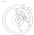
- Fig. 2 is an assembly plan view of a wheel train and its associated components of the time measurement device 1.
- the time measurement device 1 is a wristwatch and when using it, a user wraps a belt attached to the body of the wristwatch around the wrist.
- the time measurement device 1 of this embodiment includes, as its major components, a generator section A for generating an alternating current power, a power source B for rectifying the alternating current power from the generator section A, multiplying the rectified voltage, storing the multiplied voltage, and feeding the power to each block in the device, a controller 23 which, includes a generation state detector 91 (Fig.
- a second hand driving mechanism CS for driving a second hand with a step motor 10
- an hour/minute hand driving mechanism CHM for driving a minute hand and a hour hand with a step motor
- a second hand drive unit 30S for driving the second hand driving mechanism CS in accordance with a control signal from the controller 23
- an hour/minute hand drive unit 30HM for driving the hour/minute hand driving mechanism CHM in accordance with a control signal from the controller 23
- a crown 80 (Fig. 2) that constitutes an external control unit 100 which inputs commands to shift an operation mode of the time measurement device 1 from a time display mode to a calendar setting mode or a time setting mode or to force the operation mode into a power save mode to be described later.
- the controller 23 switches between a display mode (a normal operation mode) for presenting a time display by driving the second hand driving mechanism CS and the hour/minute hand driving mechanism CHM, and a power save mode for saving power by stopping the power supplied to the second hand driving mechanism CS and the hour/minute hand driving mechanism CHM.
- the operator such as the user, may force the time measurement device 1 to shift from the power save mode to the display mode by swinging the user's arm with the time measurement device in the user's hand and by detecting power generation in it.
- the detailed construction of the time measurement device 1 is now discussed.
- the controller 23 will be discussed later referring to a functional block diagram.
- the generator section A is now discussed.
- the generator section A includes a generator 40.
- the generator 40 is an alternating current generator that generates power in a generator coil 44 connected to the generator stator 42 when a generator rotor 43 rotates within a generator stator 42.
- the pinion of a generator rotor 43 is in mesh with a rotor driving wheel 46 supported by a main plate, and the rotor driving wheel 46 is in turn in mesh with an oscillating weight wheel 57.
- the rotation of the oscillating weight wheel 57 is transferred to the generator rotor 43 at an increased rotation rate.
- An oscillating weight 45 is fitted into the oscillating weight wheel 57 to form a unitary structure, and along with the rotation of the oscillating weight 45, the oscillating weight wheel 57 also rotates.
- the oscillating weight wheel 57 has an inner race 58 on its inner circumference, and the inner race 58 is affixed to an unshown oscillating weight support with a screw 59. A plurality of unshown balls are inserted between the inner race 58 and the oscillating weight wheel 57.
- the oscillating weight 45 picks up the motion, and integrally rotates with the oscillating weight wheel 57.
- the rotation of the oscillating weight wheel 57 is transferred to the generator rotor 43 via the rotor driving wheel 46.
- the inner race 58 remains unrotated even when the oscillating weight 45 is rotated, and prevents the screw 59 and the like supporting the oscillating weight 45 from becoming loose.
- the generator 40 generates power by allowing the generator rotor 43 to be rotated at a high speed in response to the motion of the user's arm.
- the power generated by the generator 40 is stored in a high-capacitance capacitor 48 via a rectifier circuit 47 (see Fig. 1).
- the power source section B is now discussed.
- the power source section B includes a limiter circuit LM for preventing an excessive voltage from being applied to a later circuit stage, a diode 47 working as the rectifier circuit, the high-capacitance capacitor 48, and a voltage multiplier circuit 49.
- the limiter circuit LM, the rectifier circuit (diode 47), and the high-capacitance capacitor 48 are arranged in that order from the power generator side A as shown in Fig. 1, but alternatively, the rectifier circuit (diode 47), the limiter circuit LM, and the high-capacitance capacitor 48 may be arranged in that order.
- the voltage multiplier circuit 49 raises or lowers the voltage in multiple steps using a plurality of capacitors 49a, 49b, and 49c, thereby adjusting the voltage supplied to the second hand drive unit 30S and hour/minute hand drive unit 30HM using a control signal ⁇ 11 from the controller 23.
- the second hand driving mechanism CS is first discussed.
- the step motor 10 used in the second hand driving mechanism CS is also called a pulse motor, a stepping motor, step-wise rotating motor, or a digital motor, and is a motor that is driven by a pulse and functions as an actuator for digital control devices.
- Miniature and light-weight stepping motors find widespread use as an actuator for compact electronic devices or information devices suitable for portable applications. Typical of these electronic devices are time measurement devices, such as an electronic watch, a timing switch and a chronograph.
- the stepping motor 10 of this embodiment includes a drive coil 11 that produces magnetic field with a drive pulse supplied thereto by the second hand drive unit 30S, a stator 12 excited by the drive coil 11, and a rotor 13 that rotates within the stator 12 in response to magnetic field applied.
- the stepping motor 10 is of a PM (permanent magnet rotation) type, in which the rotor 13 is constructed of two-pole disklike permanent magnets.
- the stator 12 is provided with magnetically saturated sections 17 so that different magnetic poles are generated at phases (poles) 15 and 16 surrounding the rotor 13 in response to the magnetic field generated by the drive coil 11.
- an inner notch 18 is formed in the inner circumference of the stator 12 at its appropriate position to generate cogging torque to stop the rotor 13 at its adequate position.
- the rotary motion of the rotor 13 in the stepping motor 10 is transferred to a second hand 55 via a wheel train 50 which is composed of a second wheel (second indicating wheel) 52 and a second intermediate wheel 51 coupled with the rotor 13 via the rotor pinion, and second display is thus presented.
- a wheel train 50 which is composed of a second wheel (second indicating wheel) 52 and a second intermediate wheel 51 coupled with the rotor 13 via the rotor pinion, and second display is thus presented.
- a stepping motor 60 used in the hour/minute hand driving mechanism has the same construction as the stepping motor 10.
- the stepping motor 60 includes a drive coil 61 for producing magnetic field in response to a drive pulse supplied thereto by the hour/minute hand drive unit 30HM, a stator 62 excited by the drive coil 61, and a rotor 63 that rotates within the stator 62 under the magnetic field.
- the stepping motor 60 is of a PM (permanent magnet rotation) type, in which the rotor 63 is constructed of two-pole disklike permanent magnets.
- the stator 62 is provided with magnetically saturated sections 67 so that different magnetic poles are generated at phases (poles) 65 and 66 surrounding the rotor 63 in response to the magnetic field generated by the drive coil 61.
- an inner notch 68 is formed in the inner circumference of the stator 62 at its appropriate position to generate cogging torque to stop the rotor 63 at its adequate position.
- the rotary motion of the rotor 63 in the stepping motor 60 is transferred to a wheel train 70 which is composed of a second wheel and pinion 71 in mesh with the rotor via its pinion, a third wheel and pinion 72, a center wheel (a minute hand mounting wheel) and pinion 73, a minute wheel 74, and an hour wheel (an hour hand mounting wheel) 75.
- a minute hand 76 is mounted on the center wheel 73
- an hour hand 77 is mounted on the hour wheel 75.
- these hands indicate the hour and minute.
- the wheel train 70 may be connected to a transmission mechanism (for example, an intermediate hour wheel, an intermediate date wheel, a date indicator driving wheel, and a date indicator for indicating the day) for indicating the year, the month, and the day (calendar), although it is not shown here.
- a transmission mechanism for example, an intermediate hour wheel, an intermediate date wheel, a date indicator driving wheel, and a date indicator for indicating the day
- a calendar corrector wheel train for example, a first calendar corrector drive wheel, a second calendar corrector drive wheel, a calendar corrector wheel, a date wheel, etc.
- a calendar corrector wheel train for example, a first calendar corrector drive wheel, a second calendar corrector drive wheel, a calendar corrector wheel, a date wheel, etc.
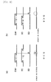
- the second hand drive unit 30S and the hour/minute hand drive unit 30HM are now discussed. Since both the second hand drive unit 30S and the hour/minute hand drive unit 30HM are identical in construction, the second hand drive unit 30S only is representatively discussed.
- the second hand drive unit 30S supplies the stepping motor 10 with various drive pulses under the control of the controller 23.
- the second hand drive unit 30S includes a bridge circuit composed of a p-channel MOS transistor 33a and an n-channel MOS transistor 32a in a series connection and a p-channel MOS transistor 33b and an n-channel MOS transistor 32b in a series connection.
- the second hand drive unit 30S includes p-channel MOS transistors 33a and 33b, rotation detecting resistors 35a and 35b, respectively connected to the p-channel MOS transistors 33a and 33b, and p-channel MOS transistors 34a and 34b respectively supplying chopper pulses to the resistors 35a and 35b.
- MOS transistors 32a, 32b, 33a, 33b, 34a and 34b By supplying the gate electrodes of MOS transistors 32a, 32b, 33a, 33b, 34a and 34b with control pulses having different polarities and different pulse widths at their respective timings, the drive coil 11 receive drive pulses having different polarities, or detection pulses for generating induced voltage for rotation detection or magnetic field detection of the rotor 13.
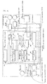
- controller 23 The construction of the controller 23 is discussed, referring to Fig. 4.
- Fig. 4 is a functional block diagram of the controller 23 and its associated blocks.
- the controller 23 includes, as its major blocks, a pulse synthesizing circuit 22, a mode setting circuit 90, a time information memory 96, and a drive control circuit 24.
- the pulse synthesizing circuit 22 includes an oscillator circuit that generates a reference pulse having a stable frequency using a reference oscillator element 21 such as a crystal oscillator, and a synthesizing circuit which combines a pulse, which is obtained by frequency-dividing the reference pulse, and the reference pulse, thereby synthesizing pulse signals having different pulse widths and different timings.
- the mode setting circuit 90 includes a generation state detector 91, a set value switch 95 for switching the set value for detecting a generation state, a voltage detector circuit 92 for detecting a charging voltage Vc for a high-capacitance capacitor 48, a central control circuit 93 for controlling the mode of the time display in accordance with the generation state and for controlling a voltage multiplication rate in response to the charging voltage, and a mode memory 94 for storing the mode.
- the generation state detector 91 includes a first detector circuit 97 which compares a generated voltage Vgen of the generator 40 with a set voltage value Vo to determine whether power generation is detected, and a second detector circuit 98 which compares a set time value To with a generation running time Tgen during which is obtained a generated voltage Vgen equal to or greater than a low set voltage value Vbas significantly smaller than the set voltage value Vo, in order to determine whether power generation is detected.
- the generation state detector 91 determines that the device is in a power generation state, if either the first detector circuit 97 or the second detector circuit 98 detects the power generation.
- first detector circuit 97 The constructions of the first detector circuit 97 and second detector circuit 98 are now discussed, referring to Fig. 5.
- the first detector circuit 97 is composed of a comparator 971, a reference voltage source 972 for generating a constant voltage Va, a reference voltage source 973 for generating a constant voltage Vb, a switch SW1, and a retriggerable monostable multivibrator 974.
- the voltage generated by the reference voltage source 972 is a set voltage value Va in the display mode, while the voltage generated by the reference voltage source 973 is a set voltage value Vb in the power save mode.
- the reference voltage sources 972 and 973 are selectively connected to a positive input terminal of the comparator 971 via the switch SW1.
- the switch SW1 is controlled by the set value switch 95, and connects the positive input terminal of the comparator 971 to the reference voltage source 972 in the display mode, or to the reference voltage source 973 in the power save mode.
- the voltage Vgen generated in the power generator section A is fed to a negative input terminal of the comparator 971.
- the comparator 971 thus compares the generated voltage Vgen with the set voltage value Va or the set voltage value Vb, and outputs an "H” level comparison result signal when the generated voltage Vgen is lower than one of these voltage values (namely, has a larger amplitude), and outputs an "L” level comparison result signal when the generated voltage Vgen is higher than one of these voltage values (namely, has a smaller amplitude).
- the retriggerable monostable multivibrator 974 Triggered at the rising edge of the comparison result signal transitioned from an "L” level to an “H” level, the retriggerable monostable multivibrator 974 rises from an “L” level to an “H” level, and generates a signal that rises from an "L” level to an “H” level a predetermined duration of time later.
- a measurement time is reset to newly start time measurement.
- the operation of the first detector circuit 97 is discussed.
- the switch SW 1 selects the reference voltage source 972, and the set voltage value Va is fed to the comparator 971.
- the comparator 971 compares the set voltage value Va and the generated voltage Vgen and outputs the comparison result signal.
- the retriggerable monostable multivibrator 974 rises from an "L” level to an "H” level in synchronization with the rising edge of the comparison result signal.
- the switch SW1 selects the reference voltage source 973 and the set voltage value Vb is fed to the comparator 971. Since the generated voltage Vgen is not in excess of the set voltage value Vb in this case, no trigger is input to the retriggerable monostable multivibrator 974. A voltage detection signal Sv remains low.
- the first detector circuit 97 generates the voltage detection signal Sv by comparing the generated voltage Vgen with the set voltage value Va or Vb depending on the mode.
- the second detector circuit 98 is composed of an integrating circuit 981, a gate 982, a counter 983, a digital comparator 984, and a switch SW2.
- the integrating circuit 981 is composed of a MOS transistor 2, a capacitor 3, a pull-up resistor 4, an inverter 5, and an inverter 5'.
- the generated voltage Vgen is coupled to the gate of the MOS transistor 2, and in response to the generated voltage Vgen, the MOS transistor 2 repeats on/off actions, controlling the charging of the capacitor 3.
- the switching means is constructed of MOS transistors
- the integrating circuit 981 is manufactured of a low-cost CMOS-ICs including the inverter 5.
- the switching element and voltage detection means may be manufactured of bi-polar transistors.
- the pull-up resistor 4 pulls up the voltage V3 of the capacitor 3 to the potential Vss during a non-power generation period, and has a function of creating a leakage current during the non-power generation period.
- the pull-up resistor 4 has a high resistance value ranging from several tens of M ⁇ to several hundreds of M ⁇ , and may be constructed of a MOS transistor having a large on resistance.
- the inverter 5, connected to the capacitor 3, detects the voltage value V3 of the capacitor 3, and the detection signal Vout is output by inverting the output of the inverter 5.
- the threshold value of the inverter 5 is designed to be the set voltage value Vbas substantially smaller than the set voltage value Vo used in the first detector circuit 97.
- the gate 982 is supplied with the reference signal from the pulse synthesizing circuit 22 and the detection signal Vout.
- the counter 983 therefore counts the reference signal while the detection signal Vout remains high.
- the resulting count is input to one input of the digital comparator 984.
- the other input of the digital comparator 984 is supplied with the set time value To corresponding to set time.
- the digital comparator 984 is supplied with a set time value Ta via the switch SW2
- the digital comparator 984 is supplied with a set time Tb via the switch SW2.
- the switch SW2 is controlled by the set value switch 95.
- the digital comparator 984 outputs its comparison result as a generation running time detection signal St in synchronization with the falling edge of the detection signal Vout.
- the generation running time detection signal St is at an "H” level when the set time is exceeded, and is at an "L” level when the set time is not exceeded.
- the generator 40 When the power generator section A starts generating an alternating current, the generator 40 outputs the generated voltage Vgen through the diode 47.
- the MOS transistor 2 When the value of the generated voltage Vgen at the start of generation falls down to Vss from Vdd, the MOS transistor 2 is turned on, starting charging the capacitor 3. The potential of the capacitor 3 is fixed to Vss through the pull-up resistor 4 during the non-power generation period, but when the charging of the capacitor 3 starts at the start of power generation, the potential V3 starts rising up to Vdd.
- the MOS transistor 2 When the MOS transistor 2 is turned off with the generated voltage Vgen increasing to Vss, the charging of the capacitor 3 stops, but the voltage V3 is maintained by the capacitor 3. The above process is repeated as long as the power generation continues. The voltage V3 rises to Vdd, and is stabilized there.
- the detection signal Vout namely, the output of the inverter 5' is transitioned from an "L” level to an “H” level, and a power generation is thus detected.
- Any response time until the power generation detection may be set by connecting a current limiting resistor, by changing the performance of the MOS transistor to adjust the charging current to the capacitor 3, or by changing the capacitance of the capacitor 3.
- the MOS transistor 2 When the power generation stops, the generated voltage Vgen reliably remains at the level of Vdd, the MOS transistor 2 remains turned off. Although the voltage V3 is maintained by the capacitor 3 for some time, V3 gradually falls from Vdd to Vss because the pull-up resistor 4 drains the charge at the capacitor 3 by means of a small leakage current therethrough. When the voltage V3 falls below the threshold value of the inverter 5, the detection signal Vout, namely, the output of the inverter 5' is transitioned from an "H" level to an “L” level, and no-power generation is thus detected. The response time to this detection may be adjusted by varying the resistance of the pull-up resistor 4 or by adjusting the leakage current of the capacitor 3.
- the gated reference signal is counted by the counter 983. The count is compared with the value corresponding to the set time at a timing T1 by the digital comparator 984.
- the generation running time detection signal St is transitioned from an "L" level to an "H" level.
- the voltage level and period (frequency) of the generated voltage Vgen change depending on the rotational speed of the generator rotor 43. Specifically, the higher the rotational speed, the greater the generated voltage Vgen becomes in amplitude, and the shorter the period becomes. For this reason, the length of the output hold period (generation running time) of the detection signal Vout changes depending on the rotational speed of the generator rotor 43, i.e., the level of the power generated by the generator 40.
- the output hold time is ta
- the rotational speed of the generator rotor 43 is high, i.e., when the strength of generated power is strong, the output hold time is tb.
- Both output hold times are related as ta ⁇ tb. In this way, the strength of power generated by the generator 40 is determined from the length of the output hold time of the detection signal Vout.
- the set voltage value Vo and the set time value To are switched under the control of the set value switch 95.
- the set value switch 95 changes set values Vo and To for the first and second detector circuits 97 and 98 in the generation state detector 91.
- set values Va and Ta in the display mode are lower than set values Vb and Tb in the power save mode. Therefore, a higher power is required to switch to the display mode from the power save mode.
- the level of power which may be generated in the ordinary level of motion the user exerts on the time measurement device 1 while normally carrying it, is not sufficient. The user may need intentionally swing the user's own arm to force the charging.
- the central control circuit 93 includes a non-power generation time measurement circuit 99 which measures a non-power generation time Tn that cannot be measured by the first and second detector circuits 97 and 98.
- the central control circuit 93 shifts the operation mode from the display mode to the power save mode when the non-power generation time Tn continues in excess of a predetermined set time.
- the mode is shifted from the power save mode back to the display mode when the following conditions are satisfied: the generation state detector 91 detects that the power generator section A is in the power generation state and the charging voltage VC at the high-capacitance capacitor 48 is high enough.
- the power source section B in this embodiment includes the voltage multiplier circuit 49, hand driving mechanisms CS and CHM are driven by allowing the voltage multiplier circuit 49 to raise the power source voltage even when the low charging voltage VC is low.
- the central control circuit 93 determines a voltage multiplication rate in accordance with the charging voltage VC, thereby controlling the voltage multiplier circuit 49.
- the charging voltage VC is compared with a set voltage value Vc to determine whether the charging voltage VC is high enough, and an affirmative answer in this determination is regarded as one condition to shift from the power save mode to the display mode.
- the central control circuit 93 includes a power save mode counter 101 for monitoring whether a command to shift to a predetermined force power save mode is issued within a predetermined duration of time, when an external control unit 100 is operated by an operator, such as a user.
- the mode set in this way is stored in the mode memory 94, and the information about the mode is fed to the drive control circuit 24, the time information memory 96, and the set value switch 95.
- the drive control circuit 24 stops supplying the pulse signals to the driving mechanisms, thereby stopping the operation of the second hand drive unit 30S and the hour/minute hand drive unit 30HM.
- the stepping motor 10 comes to a halt and the time display stops.
- the time information memory 96 is constructed of an up-down counter (not shown), and increments its count (up-counts) in response to the reference signal generated by the pulse synthesizing circuit 22 to start time measurement when the display mode is shifted to the power save mode, and stops time measurement when the power save mode is shifted to the display mode. In this way, the power save mode running time is measured as a count.
- the up-down counter decrements its count (down-counts), and the drive control circuit 24 outputs fast hand driving pulses to the second hand drive unit 30S and the hour/minute hand drive unit 30HM during the down counting.
- a control signal for stopping the issue of the fast hand driving pulse is generated and is fed to the second hand drive unit 30S and the hour/minute hand drive unit 30HM.
- the time display returns to current time.
- the time information memory 96 has the function of returning the time display presented back again to current time.
- the drive control circuit 24 produces the drive pulse corresponding to the mode in accordance with a diversity of pulses output by the pulse synthesizing circuit 22.
- the power save mode the supplying of the drive pulse is stopped.
- the fast hand driving pulse having short pulse intervals is supplied to the second hand drive unit 30S and the hour/minute hand drive unit 30HM as the drive pulse.
- the drive pulse having normal pulse intervals is supplied to the second hand drive unit 30S and the hour/minute hand drive unit 30HM.
- the external control unit 100 includes, as its major components, a crown 80 functioning as a control, and a position detector for detecting an operational position of the crown 80.
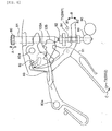
- Fig. 6 shows the construction of the external control unit 100 and its associated components.
- the external control unit 100 includes the crown 80 and a winding stem 81, and the winding stem 81 is movable in the directions of arrows A as shown.
- the winding stem 81 is engaged with a setting lever 82, and the setting lever 82 is pivotally supported about its axis 82a.
- the setting lever 82 is pivoted as the winding stem 81 moves.
- the setting lever 82 is set at one of three positions, namely, zero position, a first-step pulled position, and a second-step pulled position by a click 105A of a pressure member 105.
- the winding stem 81 is set to one of a normal hand driving state, a calendar correction state, or time setting state.
- the setting lever 82 is engaged with a yoke 83, and the yoke 83 is pivotally supported about its axis 83a. As the setting lever 82 moves, the yoke 83 pivots in the directions of arrows B.
- the yoke 83 is engaged with a clutch wheel 84 movable along the winding stem 81, and the clutch wheel 84 is moved along the winding stem 81 when the yoke 83 is pivoted.
- the yoke 83 is pivoted in the direction of arrow B1, reaching the first-step pulled position, contacting a terminal T1 forming the first switch SW1, and thereby turning the first switch SW1 on.
- the yoke 83 When the winding stem 81 is moved further, the yoke 83 is pivoted in the direction of arrow B2 as shown. A setting wheel 89 is arranged below the clutch wheel 84 as shown.
- the winding stem 81 When the winding stem 81 is set to the time setting state (the second-step pulled position), the yoke 83 is detached from the terminal T1 constituting the first switch SW1, and turning the first switch SW1 off. The yoke 83 moves the clutch wheel 84 downward, thereby causing it to engage with the setting wheel 89.
- the setting lever 82 moves the train wheel setting lever 91, thereby causing the train wheel setting lever 91 to stop the unshown second wheel while resetting the electronic circuitry.
- a calendar corrector wheel 92 is rotatably supported about the winding stem 81.
- the yoke 83 moves the clutch wheel 84 upwards, thereby causing the clutch wheel 84 to engage with the first calendar corrector wheel 92.
- the first calendar corrector wheel 92 is rotated, and thereby an unshown second calendar corrector wheel and a calendar corrector wheel in mesh with the second calendar corrector wheel are thus rotated.
- the date indicator always in mesh with the calendar corrector wheel is rotated, thus performing calendar correction.
- the states of the first switch SW1 and the second switch SW2 in the above operation are summarized as follows: zero-step ⁇ first-step pulled ⁇ second-step pulled SW1 OFF ⁇ ON ⁇ OFF SW2 OFF ⁇ OFF ⁇ ON
- the position detector 100A includes a latch circuit 110 which captures and holds a second switch state signal SSW2 at the rising edge of a first clock signal CLK1 as a latch timing when the second switch state signal SSW2, corresponding to the state of the second switch SW2, is transitioned from an "H" level to an "L” level, an AND gate 111 with its one input terminal connected to the latch circuit and the other input terminal receiving a first switch state signal SSW1 corresponding to the ON/OFF state of the first switch SW1, a differentiating circuit 112 for differentiating the output of the AND gate 111 to output a differentiated signal SD, and an AND gate 113 for AND gating the count signal SC from the power save mode counter 101 and the differentiated signal SD to output a force PS (power save) signal PS.
- a latch circuit 110 which captures and holds a second switch state signal SSW2 at the rising edge of a first clock signal CLK1 as a latch timing when the second switch state signal SSW2, corresponding to the state of the second switch SW2, is
- the latch circuit 110 in the position detector 100A captures and holds the second switch state signal SSW2, corresponding to the state of the second switch SW2 at the rising edge of the first clock signal CLK1 as a latch timing when the second switch state signal SSW2 is transitioned from an "H" level to an "L” level.
- the first clock signal CLK1 is a clock signal that is initialized with the second switch state signal SSW2 at an "H” level, and is output with the second switch state signal SSW2 at an "L” level.
- the first clock signal CLK1 is transitioned from an “L” level to an “H” level after the time corresponding to the frequency of the first clock signal CLK1 elapses subsequent to the transition of the second switch state signal SSW2 from an "H” level to an “L” level.
- the AND gate 111 functions as a gate that blocks the flow of the first switch state signal SSW1 to the power save mode counter 101 and the differentiating circuit 112 until the first clock signal CLK1 is transitioned to an "H" level after the winding stem 81 is disengaged from the second-step pulled position. Specifically, the releasing of the time setting in which the winding stem 81 is moved in the order of the two-step pulled position ⁇ the first-step pulled position ⁇ zero step position is distinctly discriminated from a force power save mode operation in which the winding stem 81 is moved in the order of the zero step position ⁇ the first-step pulled position ⁇ the zero step position.
- the power save mode counter 101 starts counting, and keeps the count signal SC at an "H” level until a predetermined count time has elapsed.
- the differentiating circuit 112 differentiates the output of the AND gate 111, thereby outputting the differentiated signal SD. In other words, the differentiating circuit 112 detects the falling edge of the first switch state signal SS1, thereby outputting an "H" level differentiated signal SD.
- the AND gate 113 When the "H" level differentiated signal SD is output while the count signal SC is at an "H” level as shown Fig. 8(a), the AND gate 113 outputs the force PS (power save) signal PS.
- the calendar correction release operation in which the winding stem 81 is operated to take a series of positions of the first-step pulled position ⁇ the zero step position during the "L" level period of the count signal SC after the set time T1 elapses, is distinctly discriminated from the already discussed shifting operation to the force power save mode, in which the winding stem 81 takes a series of positions of (the zero step position) ⁇ the first-step pulled position ⁇ the zero step position.
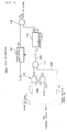
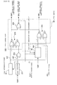
- the mode control unit 200 includes the time information memory 96 which includes an up-down counter, stores the power save mode running time by up-counting it, down-counts the power save mode running time to return to current time, and provides its count signal SCT, which is at an "L" level when the count is other than zero, a carried state detector 201 which outputs an "H" level carried state detection signal SPT in response to the voltage Vgen generated by the generator 40 when the time measurement device is in its carried state, an AND gate 202 which receives the carried state detection signal SPT at one input terminal and receives, at the other input terminal, a power save mode control signal SPS which is driven to an "H” level in the power save mode, a non-power generation time measurement circuit 99 which measures the elapsed time from the start of the non-power generation time in response to the voltage Vgen generated by the generator 40, and outputs an "H" level non-power generation elapsed time SNG after the elapse of a predetermined non-power generation time, and a mode memory 94
- the mode memory 94 includes a first latch circuit 203 which latches the count signal SCT at the timing of the rising edge of the output signal of the AND gate 202 and gives its output as the return to current time control signal SRET, a second latch circuit 204 which latches the non-power generation elapsed time SNG at the timing of the rising edge of the count signal SCT, and gives its output as the normal operation mode control signal SNR, and an NOR gate 205 which NOR gates the return to current time control signal SRET and the normal operation control signal SNR, and gives its output as the power save mode control signal SPS.
- the mode control unit 200 is in its normal operation mode at the start of the operation.
- the non-power generation time measurement circuit 99 measures the non-power generation elapsed time.
- the non-power generation time measurement circuit 99 drives the non-power generation elapsed time SNG to an "H" level.
- the normal operation control signal SNR output by the second latch circuit 204 is driven to an "L” level, while the power save mode control signal SPS output by the NOR gate 205 is driven to an "H” level, and the time measurement device is switched to the power save mode.
- the time information memory 96 is activated (into an active state) and stores the time information in the power saving mode by up-counting the running time, and its count signal SCT is at an "L" level because the count is other than zero.
- the carried state detector 201 When the carried state detector 201 detects a carried state, driving the carried state detection signal SPT to an "H” level, the output of the AND gate 202 is driven to an "H” level, and the first latch circuit 203 drives the return to current time control signal SRET to an "H” level.
- the time measurement device continues return to time process until the count at the time information memory 96 becomes zero.
- the return to time process is regarded as complete, and the time information memory 96 drives the count signal SCT to an "H" level.
- the normal operation control signal SNR which is the output of the second latch circuit 204, is driven to an "H" level, thereby causing the time measurement device to return to the normal operation mode.
- the power save mode is entered in the same manner as when the non-power generation time measurement circuit 99 has measured the predetermined non-power generation time.
- the return to current time unit 300 includes the pulse synthesizing circuit 22 which generates and outputs a pulse signal ⁇ 1 providing one pulse per second, a pulse signal ⁇ 1/10 providing one pulse per ten seconds, a pulse signal ⁇ 32 providing 32 pulses per second, and a pulse signal ⁇ 256 providing 256 pulses per second.
- the pulse signal ⁇ 1 from among them, is used to drive the second hand in the normal operation mode, and the pulse signal ⁇ 1/10 is used to drive the hour/minute hands in the normal operation mode.
- the pulse signal ⁇ 32 is used to drive the second hand back to current time with the fast hand driving pulse
- the pulse signal ⁇ 256 is used to drive the hour/minute hands back to current time with the fast hand driving pulses.
- the return to current time unit 300 includes the time information memory 96, the drive control circuit 24, the hand drive unit 30HM, the hand drive unit 30S, the hour/minute motor 60, and the second motor 10.
- the return to current time unit 300 further includes an AND gate 302 which receives the pulse signal ⁇ 1/10 at one input terminal and, at the other input terminal, an hour/minute count signal SCHM output by an OR gate 330 to be described later, and outputs a signal for causing an hour/minute difference counter 301, which is an up-down counter in the time information memory, to up-count a difference between the current time indicated by the hour and minute hands and the time indicated at a stop state, a zero detector 303 for determining whether the count at the hour/minute difference counter 301 is zero, i.e., whether the current time indicated by the hour and minute hands coincides with the displayed time, an AND gate 304 which receives the inverted output of the zero detector 303 at its first input terminal, the return to current time control signal SRET at its second input terminal, and the pulse signal ⁇ 256 at its third input terminal, while outputting a signal for causing the hour/minute difference counter 301 to down-count during the return to current time process, an AND gate 305 which receives the
- the return to current time unit 300 further includes an AND gate 312 which receives the pulse signal ⁇ 1 at one input terminal and, at the other input terminal, a second count signal SCSC output by an OR gate 331 to be described later, and outputs a signal for causing a second difference counter 311, which is an up-down counter in the time information memory, to up-count a difference between the current time indicated by the second hand and the time indicated at a stop state, a zero detector 313 for determining whether the count at the second difference counter 311 is zero, i.e., whether the current time indicated by the second hand coincides with the displayed time, an AND gate 314 which receives the inverted output of the zero detector 313 at its first input terminal, the return to current time control signal SRET at its second input terminal, and the pulse signal ⁇ 32 at its third input terminal, while outputting a signal for causing the second difference counter 311 to down-count during the return to current time process, an AND gate 315 which receives the pulse signal ⁇ 1 at one input terminal and the output of
- the return to current time unit 300 further includes an AND gate 320 which receives the outputs of the zero detector 303 and the zero detector 313, and outputs a zero detection signal S0, an OR gate 330 which receives the return to current time control signal SRET at one input terminal and the power save mode control signal SPS at the other input terminal while outputting an hour/minute count signal SCHM by AND gating the two input control signals, and an OR gate 331 which receives the return to current time control signal SRET at one input terminal and the power save mode control signal SPS at the other input terminal while outputting the second count signal SCSC by AND gating the two input control signals.
- the AND gate 302, AND gate 304, AND gate 312, and AND gate 314 all output "L" level output signals.
- the pulse signal ⁇ 1/10 is output to the drive unit 30HM through the AND gate 305 and OR gate 307, and the drive unit 30HM drives the hour/minute motor 60, thereby driving the hour and minute hands every 10 seconds.
- the pulse signal ⁇ 1 is output to the drive unit 30S through the AND gate 315 and OR gate 317, and the drive unit 30S drives the second motor 10, thereby driving the second hand every second.
- the AND gate 302 When the mode memory 94 outputs an "H" level power save mode control signal SPS, the AND gate 302 outputs the pulse signal ⁇ 1/10 to cause the hour/minute difference counter 301 to up-count, and the hour/minute difference counter 301 thus counts the difference between the current time indicated by the hour and minute hands and the time at a stop state.
- the AND gate 312 outputs the pulse signal ⁇ 1 to cause the second difference counter 311 to up-count, and the second difference counter 311 up-counts the difference between the current time indicated by the second hand and the time at a stop state.
- the output of the zero detector 303 is at an "L” level with its inverted form at an "H” level.
- the AND gate 304 outputs the pulse signal ⁇ 256 to cause the hour/minute difference counter 301 to down-count while outputting the pulse signal ⁇ 256 to the AND gate 306.
- the hour/minute difference counter 301 up-counts at the timing of the pulse signal ⁇ 1/10 for the down-counting, and the return to current time process thus accounts for the time elapse in the middle of the return to current time action.
- the AND gate 306 outputs the pulse signal ⁇ 256 to the drive unit 30HM, and the drive unit 30HM drives the hour/minute motor 60, thereby driving the hour and minute hands every 1/256 second.
- the time indication by the hour and minute hands coincides with the current time, and the pulse signal ⁇ 1/10 is again output to the drive unit 30HM via the AND gate 305 and OR gate 307.
- the drive unit 30HM drives the hour/minute motor 60, thereby driving the hour and minute hands every 10 seconds.
- the output of the AND gate 312 is transitioned to an "L” level.
- the output of the zero detector 313 is at an "L” level with its inverted form at an "H” level.
- the AND gate 314 outputs the pulse signal ⁇ 32 to cause the AND gate 312 to down-count, while outputting the pulse signal ⁇ 32 to the AND gate 316.
- the AND gate 316 outputs the pulse signal ⁇ 32 to the drive unit 30S, and the drive unit 30S drives the second motor 10, thereby driving the second hand every 1/32 second.
- the indication by the second hand coincides with the current time.
- the pulse signal ⁇ 1 is again output to the drive unit 30S via the AND gate 315 and OR gate 317, and the drive unit 30S drives the second motor 10, thereby driving the second hand every second.
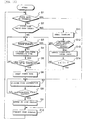
- Fig. 11 shows an operational flow diagram focusing on the shifting of the time measurement device into the forced power save mode in the embodiment of the present invention.
- the controller 23 determines whether the time measurement device is in the power save mode (step S1).
- step S1 When it is determined in step S1 that the time measurement device is in the power save mode (Yes in step S1), the process goes to step S7 to be described later.
- the controller 23 causes the mode memory to store the power save mode.
- the drive control circuit 24 controls the second hand drive unit 30S and the hour/minute hand drive unit 30HM, thereby stopping the hour/minute motor and the second motor.
- the time information memory 96 up-counts the time information corresponding to the power save mode running time to perform the return to current time process (see step S9) to be described later (step S7), and determines whether the generator 40 generates power equal to or higher than a predetermined electromotive force that serves as a criterion as to whether to shift to the display mode (step S8).
- step S8 When it is determined in step S8 that the generator 40 fails to generate power equal to or higher than the predetermined electromotive force that serves as a criterion whether to shift to the display mode, in other words, it is determined that the time measurement device needs to continue the power save mode (No in step S8), the process returns to step S7, and the time information corresponding to the elapsed time of the power save mode is continuously up-counted.
- step S8 When it is determined in step S8 that the generator 40 generates power equal to or higher than the predetermined electromotive force that serves as a criterion whether to shift to the display mode, in other words, it is determined that the time measurement device needs to shift to the display mode (Yes in step S8), the time measurement device switches the operation mode from the power save mode to the display mode, and performs the return to current time process in accordance with the count at the time information memory 96 (step S9).
- the time information memory 96 down-counts its count and the pulse signal for the fast hand driving is provided until the time information memory 96 reaches the zero count.
- step S10 The time display continues (step S10), and the process returns to step S1 to repeat the same steps.
- the central control circuit 93 determines whether there is an electromotive force, i.e., whether the generator 40 generates power (step S3).
- step S3 When it is determined in step S3 that there is an electromotive force (Yes in step S3), the process goes to step S10 and the time displaying continues (step S10), and the process starts over with step S1.
- step S3 When it is determined in step S3 that there is no electromotive force, i.e., no power is generated (No in step S3), the non-power generation time measurement circuit 99 in the central control circuit 93 up-counts the non-power generation time Tn (step S4).
- the central control circuit 93 determines whether the non-power generation time Tn has continued in excess of a predetermined time (step S5).
- step 5 When it is determined in step 5 that the non-power generation time Tn has yet to reach the predetermined time (No in step S5), the process returns to step S3 to repeat steps S3 through S5.
- step S6 When it is determined in step S5 that the non-power generation time Tn has continued in excess of the predetermined time, the time measurement device automatically stops the time displaying and shifts to the power save mode (step S6).
- the time measurement device After performing steps S7 through S10, the time measurement device returns back to step S1 to repeat the same steps.
- the time measurement device 1 of this embodiment stops the time displaying and then shifts into the power save mode depending on the presence or absence of power generation, and resumes the time displaying when power generation is detected, and the operator, such as the user, may force the time measurement device 1 into the power save mode at the operator's discretion.
- energy stored in the high-capacitance capacitor 48 is reliably conserved.
- the time measurement device 1 measures the non-power generation time Tn, and will not shift into the power save mode unless the non-power generation time exceeds the predetermined time. Since the operator, such as the user, can arbitrarily (forcibly) cause the time measurement device 1 to shift into the power save mode by operating the crown as the external control unit, energy saving is more reliably promoted at a condition matching the operator.
- the crown is operated to forcibly shift into the power save mode, and other operations (e.g., time setting operation) require particular steps which are different from those of the forced power save mode in terms of the time required to complete each operation and the transitional states of each operation.
- the operator such as the user, is thus free from an erroneous shift into the power save mode, and the ease of use of the time measurement device is still assured.
- the above embodiment has been discussed in conjunction with the time measurement device, which presents time display using analog hands driven by the stepping motor 10 and the stepping motor 60.
- the present invention may be implemented in a digital time measurement device, which present time display using an LCD, for example.
- the operator such as the user, forces the device into the power save mode, saving power consumed by the LCD and allowing the device to continuously measure time for a long period of time.
- the above embodiment has been discussed in conjunction with the time measurement device, which simultaneously stops two stepping motors 10 and 60 to shift to the power save mode.
- the power save mode may be divided in two phases: at a first phase, only the stepping motor 10 for the second hand is stopped, and at a second phase of the power save mode, the stepping motor 60 for the hour and minute hands is further stopped.
- the above embodiment has been discussed in conjunction with the time measurement device having the two motors for indicating the hour, the minute and the second.
- the present invention may be implemented in a time measurement device which employs a single motor for indicating the hour, the minute and the second.
- the present invention may be implemented in a time measurement device that employs three or more motors.
- the generator 40 is an electromagnetic generator, in which the rotary motion of the oscillating weight 45 is transferred to the rotor 43, and the voltage Vgen is generated in the output coil 44 in response to the rotation of the rotor 43.
- the present invention is not limited to this arrangement.
- the generator 40 may be the one in which an electromotive force is generated by a rotary motion that is caused by the restoring force of a mainspring, or may be the one in which externally generated vibration or displacement or self-generated vibration or displacement may be exerted on a piezoelectric member to generate power by means of the piezoelectric effect.
- the generator 40 may be the one which generates power through photoelectric conversion, taking advantage of sunlight or the like.
- the generator 40 may be the one which generates power by temperature difference between one location and the other location.
- a plurality of above generators may be arranged.
- Each of the generators having its power generation principle suited to a given condition of usage may be singly used to generate power, or the plurality of generators may be concurrently used to generate power.
- the above embodiment has been discussed in conjunction with the time measurement device 1 of a wristwatch type.
- the present invention is not limited to the wristwatch.
- the present invention may be applied to a pocket watch.
- the present invention may be applied to portable electronic devices including a calculator, a portable telephone, a portable personal computer, an electronic pocketbook, a portable radio, and a portable video tape recorder.
- the reference potential (GND) is set to Vdd (high potential side), but the reference potential (GND) may be set to Vss (low potential side).
- set voltage values Vo and Vbas mean the potential difference to a detection level set to the high potential side with respect to Vss.
- the shifting to the power save mode from the display mode is performed referring to the position detection of the crown.
- the present invention is not limited to this arrangement.
- the operational state of a button arranged on the case of the time measurement device 1 may be detected, and the display mode may be shifted to the power save mode in accordance with the detected operational state.
- an electromagnetic switch may be employed, and in such a case, the device may be forced into the power save mode in a plant or by retailers.
- a shift inhibit mode may be introduced which inhibits the shifting from the power save mode to the normal operation mode when a predetermined condition is met.
- a portable electronic device in the power save mode is now transported.
- the normal operation mode is entered by releasing the power save mode, and unnecessary power consumption occurs regardless of its unused state.
- the portable electronic device may be set to the shift inhibit mode so that the shifting to the normal operation mode is inhibited, preventing unnecessary power consumption.
- One example of the predetermined condition may be that in a portable electronic device in a power save mode, for example, in the above time measurement device 1, the control (the crown) is left in the one-step pulled position.
- the control the crown
- a particular number preferably three or more
- buttons or switches is set to a predetermined operational state to switch between the power save mode and the shift inhibit mode.
- the device is shifted to the shift inhibit mode not only from the power save mode but also from the normal operation mode through a similar and predetermined operation.
- the device is forced into the power save mode and then to the shift inhibit mode.
- the operator such as the user, can thus shift the device into the shift inhibit mode at the user's discretion, and during use (or during storage), power consumption is reduced in an optimum manner.
- the hour/minute motor 60 and the second motor 10 utilize the same timing at which the "H" level return to current time control signals SRET are output during the return to correct time process.
- the timings for the "H" level return to current time control signals SRET for the hour/minute motor 60 and the second motor 10 may be separated not to allow the return to current time timings to coincide with each other. With this arrangement, instantaneous and sharp rise in power consumption is restricted and a reliable operation of the device thus results.
- the operator such as the user, forces the time measurement device into the power save mode at the operator's will by manipulating the control. Electrical energy stored is thus reliably saved, and power consumed in vain is more efficiently reduced than in a method in which a device automatically stops a time displaying and is shifted into a power save mode in accordance with the presence or absence of power generation.
- the operator such as the user, is free from an erroneous shift into the power save mode, and the ease of use of the time measurement device is still assured.
Landscapes
- Engineering & Computer Science (AREA)
- Physics & Mathematics (AREA)
- General Physics & Mathematics (AREA)
- Theoretical Computer Science (AREA)
- Power Engineering (AREA)
- General Engineering & Computer Science (AREA)
- Business, Economics & Management (AREA)
- Emergency Management (AREA)
- Electromechanical Clocks (AREA)
- Power Sources (AREA)
- Electric Clocks (AREA)
- Calculators And Similar Devices (AREA)
Applications Claiming Priority (6)
| Application Number | Priority Date | Filing Date | Title |
|---|---|---|---|
| JP34602898 | 1998-12-04 | ||
| JP34602898 | 1998-12-04 | ||
| JP35676398 | 1998-12-15 | ||
| JP35676398 | 1998-12-15 | ||
| JP28184899 | 1999-10-01 | ||
| JP28184899A JP3721888B2 (ja) | 1998-12-04 | 1999-10-01 | 携帯用電子機器および携帯用電子機器の制御方法 |
Publications (3)
| Publication Number | Publication Date |
|---|---|
| EP1006640A2 true EP1006640A2 (fr) | 2000-06-07 |
| EP1006640A3 EP1006640A3 (fr) | 2001-03-28 |
| EP1006640B1 EP1006640B1 (fr) | 2007-02-14 |
Family
ID=27336884
Family Applications (1)
| Application Number | Title | Priority Date | Filing Date |
|---|---|---|---|
| EP19990309644 Expired - Lifetime EP1006640B1 (fr) | 1998-12-04 | 1999-12-01 | Dispositif électronique portatif et méthode de commande du dispositif électronique portatif |
Country Status (6)
| Country | Link |
|---|---|
| US (1) | US6424600B1 (fr) |
| EP (1) | EP1006640B1 (fr) |
| JP (1) | JP3721888B2 (fr) |
| CN (1) | CN100430843C (fr) |
| DE (1) | DE69935110T2 (fr) |
| HK (1) | HK1029010A1 (fr) |
Cited By (3)
| Publication number | Priority date | Publication date | Assignee | Title |
|---|---|---|---|---|
| EP1253489A2 (fr) * | 2001-04-27 | 2002-10-30 | Seiko Instruments Inc. | Pièce d'horlogerie électronique |
| EP1321834A1 (fr) * | 2000-09-27 | 2003-06-25 | Citizen Watch Co. Ltd. | Montre electronique et son procede de commande |
| EP1326146A1 (fr) * | 2000-08-15 | 2003-07-09 | Citizen Watch Co. Ltd. | Syst me d'horlogerie lectronique et technique de commande de celui-ci |
Families Citing this family (32)
| Publication number | Priority date | Publication date | Assignee | Title |
|---|---|---|---|---|
| JP3596464B2 (ja) * | 2000-02-10 | 2004-12-02 | セイコーエプソン株式会社 | 計時装置および計時装置の制御方法 |
| US7102964B2 (en) * | 2000-02-10 | 2006-09-05 | Seiko Epson Corporation | Time keeping apparatus and control method therefor |
| US6819634B2 (en) * | 2000-08-31 | 2004-11-16 | Citizen Watch Co., Ltd. | Electronic clock |
| TW505834B (en) * | 2001-03-20 | 2002-10-11 | Ebauchesfabrik Eta Ag | Timepiece including a generator |
| JP2002305475A (ja) * | 2001-04-04 | 2002-10-18 | Kyocera Corp | 省電力状態移行方法、及び移動通信機 |
| JP3680802B2 (ja) * | 2002-02-28 | 2005-08-10 | セイコーエプソン株式会社 | 電子時計 |
| JP2004048818A (ja) * | 2002-07-08 | 2004-02-12 | Rohm Co Ltd | モータ駆動装置 |
| DE60319638T2 (de) * | 2002-08-07 | 2009-04-02 | Seiko Epson Corp. | Tragbares Informationsgerät |
| JP2006512654A (ja) * | 2002-12-30 | 2006-04-13 | コーニンクレッカ フィリップス エレクトロニクス エヌ ヴィ | 光記録担体の記録装置 |
| US20040233794A1 (en) * | 2003-02-21 | 2004-11-25 | Seiko Epson Corporation | Timepiece driving apparatus and time calculating apparatus |
| US7088256B2 (en) * | 2004-07-30 | 2006-08-08 | Motorola, Inc. | Portable electronic device and method of operation therefore |
| EP1821163A3 (fr) * | 2006-02-13 | 2012-06-13 | Ventura Watch SA | Montre avec génératarice |
| JP5256413B2 (ja) * | 2007-08-29 | 2013-08-07 | セミコンダクター・コンポーネンツ・インダストリーズ・リミテッド・ライアビリティ・カンパニー | モータ駆動回路 |
| FR2920628B1 (fr) * | 2007-08-30 | 2011-07-01 | Celsius X Vi Ii | Telephone portable muni d'une montre mecanique |
| EP2042947B1 (fr) | 2007-09-28 | 2010-12-22 | Casio Computer Co., Ltd. | Dispositif de détection de position des aiguilles et appareil incluant le dispositif |
| JP4596002B2 (ja) * | 2007-12-25 | 2010-12-08 | カシオ計算機株式会社 | 針位置検出装置および針位置検出方法 |
| JP4623140B2 (ja) * | 2008-05-28 | 2011-02-02 | カシオ計算機株式会社 | 針位置検出装置および針位置検出制御方法 |
| JP4730397B2 (ja) * | 2008-05-30 | 2011-07-20 | カシオ計算機株式会社 | 針位置検出装置 |
| US20100001699A1 (en) * | 2008-07-02 | 2010-01-07 | Murata Power Solutions | Output voltage control circuit for modular power supplies |
| JP2011247873A (ja) * | 2010-04-30 | 2011-12-08 | Seiko Instruments Inc | クロノグラフ時計 |
| JP2012073224A (ja) * | 2010-09-03 | 2012-04-12 | Seiko Instruments Inc | 電子機器、電子機器の制御方法及び電子機器の制御プログラム |
| JP2012237739A (ja) * | 2011-04-29 | 2012-12-06 | Seiko Instruments Inc | 電子時計 |
| JP2013156159A (ja) * | 2012-01-30 | 2013-08-15 | Seiko Instruments Inc | 電子時計 |
| EP2687921A1 (fr) * | 2012-07-18 | 2014-01-22 | ETA SA Manufacture Horlogère Suisse | Procédé de gestion amélioré d'un appareil électronique |
| CN103399483B (zh) * | 2013-07-31 | 2016-12-07 | 东莞宇龙通信科技有限公司 | 可穿戴设备电源管理的方法和装置 |
| CN104866077B (zh) * | 2014-02-24 | 2019-02-05 | 联想(北京)有限公司 | 一种穿戴式电子设备和基于穿戴式电子设备的控制方法 |
| JP6759543B2 (ja) | 2015-09-11 | 2020-09-23 | カシオ計算機株式会社 | 駆動装置、電子時計、および駆動装置の制御方法 |
| CN105446457A (zh) * | 2015-12-09 | 2016-03-30 | 北京金山安全软件有限公司 | 一种优化应用程序耗电的方法、装置及电子设备 |
| CN107422626B (zh) * | 2017-09-13 | 2022-10-11 | 杭州正驰达精密机械有限公司 | 一种自动锤的转轴定位结构 |
| JP6349452B1 (ja) * | 2017-11-29 | 2018-06-27 | ヤマサ醤油株式会社 | L−グルタミン酸オキシダーゼ乾燥組成物 |
| EP3712718A1 (fr) | 2019-03-22 | 2020-09-23 | ETA SA Manufacture Horlogère Suisse | Piece d'horlogerie electroniqe a detecteur de mouvement |
| EP3842876A1 (fr) * | 2019-12-24 | 2021-06-30 | The Swatch Group Research and Development Ltd | Piece d horlogerie munie d'un mouvement mecanique et d'un dispositif de correction d'une heure affichee |
Citations (6)
| Publication number | Priority date | Publication date | Assignee | Title |
|---|---|---|---|---|
| US4615625A (en) * | 1983-04-28 | 1986-10-07 | Seiko Epson Kabushiki Kaisha | Analog electronic timepiece |
| US5177714A (en) * | 1990-01-31 | 1993-01-05 | Junghans Uhren Gmbh | Autonomous radio timepiece |
| JPH0774691A (ja) * | 1993-08-31 | 1995-03-17 | Sanyo Electric Co Ltd | 折畳機構付携帯電話機 |
| EP0657793A1 (fr) * | 1993-12-10 | 1995-06-14 | Seiko Instruments Inc. | Montre électronique corrigée par radio |
| US5457664A (en) * | 1992-09-08 | 1995-10-10 | Seikosha Co., Ltd. | Energy saving timepiece |
| EP0836263A1 (fr) * | 1996-03-13 | 1998-04-15 | Citizen Watch Co. Ltd. | Bloc d'alimentation pour pieces d'horlogerie electroniques |
Family Cites Families (6)
| Publication number | Priority date | Publication date | Assignee | Title |
|---|---|---|---|---|
| JPS5296570A (en) | 1976-02-09 | 1977-08-13 | Citizen Watch Co Ltd | Power saving method of crystal wristwatch |
| JPS55158582A (en) | 1979-05-29 | 1980-12-10 | Casio Comput Co Ltd | Electronic clock |
| JPS5745484A (en) | 1980-09-03 | 1982-03-15 | Toshiba Corp | Electronic clock |
| JPS607381A (ja) | 1983-06-28 | 1985-01-16 | Seiko Instr & Electronics Ltd | 電子時計の節電機能 |
| JPS61202186A (ja) | 1985-03-05 | 1986-09-06 | Seiko Instr & Electronics Ltd | 電子時計 |
| US5457644A (en) * | 1993-08-20 | 1995-10-10 | Actel Corporation | Field programmable digital signal processing array integrated circuit |
-
1999
- 1999-10-01 JP JP28184899A patent/JP3721888B2/ja not_active Expired - Fee Related
- 1999-12-01 DE DE69935110T patent/DE69935110T2/de not_active Expired - Lifetime
- 1999-12-01 EP EP19990309644 patent/EP1006640B1/fr not_active Expired - Lifetime
- 1999-12-02 US US09/452,852 patent/US6424600B1/en not_active Expired - Lifetime
- 1999-12-03 CN CNB991277309A patent/CN100430843C/zh not_active Expired - Fee Related
-
2000
- 2000-12-06 HK HK00107840A patent/HK1029010A1/xx not_active IP Right Cessation
Patent Citations (6)
| Publication number | Priority date | Publication date | Assignee | Title |
|---|---|---|---|---|
| US4615625A (en) * | 1983-04-28 | 1986-10-07 | Seiko Epson Kabushiki Kaisha | Analog electronic timepiece |
| US5177714A (en) * | 1990-01-31 | 1993-01-05 | Junghans Uhren Gmbh | Autonomous radio timepiece |
| US5457664A (en) * | 1992-09-08 | 1995-10-10 | Seikosha Co., Ltd. | Energy saving timepiece |
| JPH0774691A (ja) * | 1993-08-31 | 1995-03-17 | Sanyo Electric Co Ltd | 折畳機構付携帯電話機 |
| EP0657793A1 (fr) * | 1993-12-10 | 1995-06-14 | Seiko Instruments Inc. | Montre électronique corrigée par radio |
| EP0836263A1 (fr) * | 1996-03-13 | 1998-04-15 | Citizen Watch Co. Ltd. | Bloc d'alimentation pour pieces d'horlogerie electroniques |
Non-Patent Citations (1)
| Title |
|---|
| PATENT ABSTRACTS OF JAPAN vol. 1995, no. 06, 31 July 1995 (1995-07-31) & JP 07 074691 A (SANYO ELECTRIC CO LTD), 17 March 1995 (1995-03-17) * |
Cited By (7)
| Publication number | Priority date | Publication date | Assignee | Title |
|---|---|---|---|---|
| EP1326146A1 (fr) * | 2000-08-15 | 2003-07-09 | Citizen Watch Co. Ltd. | Syst me d'horlogerie lectronique et technique de commande de celui-ci |
| EP1326146A4 (fr) * | 2000-08-15 | 2004-10-06 | Citizen Watch Co Ltd | Syst me d'horlogerie lectronique et technique de commande de celui-ci |
| EP1321834A1 (fr) * | 2000-09-27 | 2003-06-25 | Citizen Watch Co. Ltd. | Montre electronique et son procede de commande |
| EP1321834A4 (fr) * | 2000-09-27 | 2004-10-06 | Citizen Watch Co Ltd | Montre electronique et son procede de commande |
| US7154816B2 (en) | 2000-09-27 | 2006-12-26 | Citizen Watch Co., Ltd. | Electronic watch and electronic watch control method |
| EP1253489A2 (fr) * | 2001-04-27 | 2002-10-30 | Seiko Instruments Inc. | Pièce d'horlogerie électronique |
| EP1253489A3 (fr) * | 2001-04-27 | 2004-01-21 | Seiko Instruments Inc. | Pièce d'horlogerie électronique |
Also Published As
| Publication number | Publication date |
|---|---|
| EP1006640B1 (fr) | 2007-02-14 |
| JP3721888B2 (ja) | 2005-11-30 |
| CN1256442A (zh) | 2000-06-14 |
| US6424600B1 (en) | 2002-07-23 |
| DE69935110T2 (de) | 2007-06-28 |
| HK1029010A1 (en) | 2001-03-16 |
| JP2000235088A (ja) | 2000-08-29 |
| DE69935110D1 (de) | 2007-03-29 |
| CN100430843C (zh) | 2008-11-05 |
| EP1006640A3 (fr) | 2001-03-28 |
Similar Documents
| Publication | Publication Date | Title |
|---|---|---|
| EP1006640B1 (fr) | Dispositif électronique portatif et méthode de commande du dispositif électronique portatif | |
| EP1677166B1 (fr) | Dispositif électronique et procédé de contrôle sa consommation d'énergie | |
| JP3551861B2 (ja) | 計時装置及びその制御方法 | |
| US6396772B1 (en) | Electronic apparatus and control method for electronic apparatus | |
| JP3601376B2 (ja) | 電子機器及び電子機器の制御方法 | |
| US6628572B1 (en) | Electronic equipment and method of controlling electronic equipment | |
| JP3830289B2 (ja) | 電子機器および計時装置 | |
| JP3601375B2 (ja) | 携帯用電子機器及び携帯用電子機器の制御方法 | |
| JP4349388B2 (ja) | 電子機器、電子機器の制御方法、計時装置、および計時装置の制御方法 | |
| JP3791263B2 (ja) | 携帯用電子機器、携帯用電子機器の制御方法ならびに計時装置および計時装置の制御方法 | |
| JP3654018B2 (ja) | 計時装置および計時装置の制御方法 | |
| JP3654056B2 (ja) | 電子時計及び電子時計の制御方法 | |
| JP4055446B2 (ja) | 電子機器、電子機器の制御方法、計時装置、および計時装置の制御方法 | |
| JP3906715B2 (ja) | 電子機器及び電子機器の制御方法 | |
| JP3906720B2 (ja) | 携帯用電子機器及び携帯用電子機器の制御方法 | |
| JP2002357679A (ja) | 携帯用電子機器および携帯用電子機器の制御方法 | |
| JP4311394B2 (ja) | 計時装置、携帯用電子機器および計時装置の制御方法 | |
| JP2005055449A (ja) | 電子時計及び電子時計の制御方法 | |
| JP2002156474A (ja) | 電子機器及び電子機器の制御方法 | |
| JP2003232874A (ja) | 電子機器および電子機器の制御方法 |
Legal Events
| Date | Code | Title | Description |
|---|---|---|---|
| PUAI | Public reference made under article 153(3) epc to a published international application that has entered the european phase |
Free format text: ORIGINAL CODE: 0009012 |
|
| AK | Designated contracting states |
Kind code of ref document: A2 Designated state(s): CH DE FR GB LI |
|
| AX | Request for extension of the european patent |
Free format text: AL;LT;LV;MK;RO;SI |
|
| PUAL | Search report despatched |
Free format text: ORIGINAL CODE: 0009013 |
|
| AK | Designated contracting states |
Kind code of ref document: A3 Designated state(s): AT BE CH CY DE DK ES FI FR GB GR IE IT LI LU MC NL PT SE |
|
| AX | Request for extension of the european patent |
Free format text: AL;LT;LV;MK;RO;SI |
|
| RIC1 | Information provided on ipc code assigned before grant |
Free format text: 7H 02J 7/14 A, 7H 02J 7/32 B, 7G 04G 1/00 B, 7H 02J 9/00 B |
|
| 17P | Request for examination filed |
Effective date: 20010813 |
|
| AKX | Designation fees paid |
Free format text: CH DE FR GB LI |
|
| 17Q | First examination report despatched |
Effective date: 20041202 |
|
| GRAP | Despatch of communication of intention to grant a patent |
Free format text: ORIGINAL CODE: EPIDOSNIGR1 |
|
| GRAS | Grant fee paid |
Free format text: ORIGINAL CODE: EPIDOSNIGR3 |
|
| GRAA | (expected) grant |
Free format text: ORIGINAL CODE: 0009210 |
|
| AK | Designated contracting states |
Kind code of ref document: B1 Designated state(s): CH DE FR GB LI |
|
| REG | Reference to a national code |
Ref country code: GB Ref legal event code: FG4D |
|
| REG | Reference to a national code |
Ref country code: CH Ref legal event code: EP |
|
| REF | Corresponds to: |
Ref document number: 69935110 Country of ref document: DE Date of ref document: 20070329 Kind code of ref document: P |
|
| REG | Reference to a national code |
Ref country code: CH Ref legal event code: NV Representative=s name: PATENTANWAELTE SCHAAD, BALASS, MENZL & PARTNER AG |
|
| ET | Fr: translation filed | ||
| REG | Reference to a national code |
Ref country code: HK Ref legal event code: GR Ref document number: 1029010 Country of ref document: HK |
|
| PLBE | No opposition filed within time limit |
Free format text: ORIGINAL CODE: 0009261 |
|
| STAA | Information on the status of an ep patent application or granted ep patent |
Free format text: STATUS: NO OPPOSITION FILED WITHIN TIME LIMIT |
|
| 26N | No opposition filed |
Effective date: 20071115 |
|
| PGFP | Annual fee paid to national office [announced via postgrant information from national office to epo] |
Ref country code: GB Payment date: 20141126 Year of fee payment: 16 Ref country code: DE Payment date: 20141125 Year of fee payment: 16 Ref country code: CH Payment date: 20141212 Year of fee payment: 16 |
|
| PGFP | Annual fee paid to national office [announced via postgrant information from national office to epo] |
Ref country code: FR Payment date: 20141208 Year of fee payment: 16 |
|
| REG | Reference to a national code |
Ref country code: DE Ref legal event code: R119 Ref document number: 69935110 Country of ref document: DE |
|
| REG | Reference to a national code |
Ref country code: CH Ref legal event code: PL |
|
| GBPC | Gb: european patent ceased through non-payment of renewal fee |
Effective date: 20151201 |
|
| REG | Reference to a national code |
Ref country code: FR Ref legal event code: ST Effective date: 20160831 |
|
| PG25 | Lapsed in a contracting state [announced via postgrant information from national office to epo] |
Ref country code: DE Free format text: LAPSE BECAUSE OF NON-PAYMENT OF DUE FEES Effective date: 20160701 Ref country code: CH Free format text: LAPSE BECAUSE OF NON-PAYMENT OF DUE FEES Effective date: 20151231 Ref country code: LI Free format text: LAPSE BECAUSE OF NON-PAYMENT OF DUE FEES Effective date: 20151231 Ref country code: GB Free format text: LAPSE BECAUSE OF NON-PAYMENT OF DUE FEES Effective date: 20151201 |
|
| PG25 | Lapsed in a contracting state [announced via postgrant information from national office to epo] |
Ref country code: FR Free format text: LAPSE BECAUSE OF NON-PAYMENT OF DUE FEES Effective date: 20151231 |