EP0836263A1 - Bloc d'alimentation pour pieces d'horlogerie electroniques - Google Patents
Bloc d'alimentation pour pieces d'horlogerie electroniques Download PDFInfo
- Publication number
- EP0836263A1 EP0836263A1 EP97907295A EP97907295A EP0836263A1 EP 0836263 A1 EP0836263 A1 EP 0836263A1 EP 97907295 A EP97907295 A EP 97907295A EP 97907295 A EP97907295 A EP 97907295A EP 0836263 A1 EP0836263 A1 EP 0836263A1
- Authority
- EP
- European Patent Office
- Prior art keywords
- section
- power supply
- preventive
- supply unit
- electronic timepiece
- Prior art date
- Legal status (The legal status is an assumption and is not a legal conclusion. Google has not performed a legal analysis and makes no representation as to the accuracy of the status listed.)
- Granted
Links
Images


Classifications
-
- H—ELECTRICITY
- H02—GENERATION; CONVERSION OR DISTRIBUTION OF ELECTRIC POWER
- H02J—CIRCUIT ARRANGEMENTS OR SYSTEMS FOR SUPPLYING OR DISTRIBUTING ELECTRIC POWER; SYSTEMS FOR STORING ELECTRIC ENERGY
- H02J7/00—Circuit arrangements for charging or depolarising batteries or for supplying loads from batteries
- H02J7/14—Circuit arrangements for charging or depolarising batteries or for supplying loads from batteries for charging batteries from dynamo-electric generators driven at varying speed, e.g. on vehicle
-
- G—PHYSICS
- G04—HOROLOGY
- G04C—ELECTROMECHANICAL CLOCKS OR WATCHES
- G04C10/00—Arrangements of electric power supplies in time pieces
Definitions
- This invention relates to a power supply unit for an electronic timepiece, and, especially to a power supply unit for an electronic timepiece using a mechanical generator as a power generating section.
- Figure 3 is a view of a circuit block diagram of a power supply unit for a conventional electronic timepiece.
- a power generating section 1 comprises a rotating means 11 composed of an eccentric weight or the like, an accelerating oscillating wheel 12 for accelerating the rotation of the rotating means 11, a rotor 13, a generating coil 14 which generates an AC current corresponding to the rotation of the rotor 13, and the like.
- a diode 2 rectifies the AC current generated by the generating coil 4 and prevents the reversal of the flow of current from a battery section 3 illustrated below.
- a voltage detecting section 4 outputs a signal when the potential of the battery section 3 exceeds a prescribed value.
- An overcharging preventive section 5 is operated by the signal from the voltage detecting section 4 to prevent overcharge exceeding the withstand voltage of the battery section 3.
- the battery section 3, which is composed of a condenser with a large capacity accumulates the electric power generated by the generating coil 14 and outputs this electric power to a timepiece circuit 6.
- the rotating means 11 such as an eccentric weight or the like installed in a wrist timepiece
- the rotation is accelerated by the accelerating wheel 12 and transferred to the rotor 13.
- the rotor 13 is composed of a permanent magnet, which is rotated to generate an AC current in the generating coil 14.
- This AC current is rectified by the diode 2 and accumulated in the large-capacity condenser 3 used as an power storing section. This accumulated power allows the timepiece circuit 6 to operate, thus driving the electronic timepiece.
- the voltage detecting section 4 outputs a detection signal at an "L" level to operate the overcharging preventive section 5 composed of a PMOS transistor. In this manner, the AC current generated in the power generating section 1 is discharged from the overcharging preventive section 5 so that it is not accumulated in the large capacity condenser 3.
- the overcharging preventive section 5 is disposed closer to the battery section 3 than the position of the diode 2 to avoid the breakdown caused by high voltage when the diode 2 generates a reverse current.
- the maximum AC current generated by the generating coil 14 is in the order of tens of mA. Therefore, in order for the overcharging preventive section 5 to function sufficiently, the resistance of the overcharging preventive section 5 in operation is required to be in the order of tens of ohms in the case where the withstanding voltage of the large capacity condenser 3 is in the order of 2.5 V.
- a titanium-lithium ion secondary battery with a large capacity (hereinafter called "secondary battery") has recently been utilized as the battery section instead of the large-capacity condenser.
- secondary battery A titanium-lithium ion secondary battery with a large capacity
- the internal resistance of this titanium-lithium ion secondary battery is as large as tens to hundreds of ohms, the potential of the secondary battery exceeds the prescribed value if the secondary battery is used for conventional electronic timepieces as shown in Fig 3.
- the overcharging preventive section 5 if the resistance of the overcharging preventive section 5 is in the order of tens of ohms, as is conventional when the overcharging preventive section 5 starts discharging the current generated from the generating coil 14, the overcharging preventive section 5 exhibits a voltage drop across the internal resistance of the secondary battery. As a result, the voltage detecting section 4 indicates its inability to output a detection signal whereby the action of the overcharging preventive section 5 is suspended.
- the voltage detecting section 4 detects an excess of voltage to allow the overcharging preventive section 5 to start the action again. Specifically, the above procedures are repeated only by substituting the large capacity condenser for the battery section in the conventional units with a large-capacity titanium-lithium ion secondary battery. This causes an intermittent discharge action, resulting in insufficient discharge. Also, the voltage supplied to the timepiece circuit 9 is unstable resulting in fear of hindrance to the action of the timepiece.
- a power supply unit of an electronic wrist timepiece proposed in Japanese Patent Applications Laid-open No. 236332/1986 and No. 324166/1994 has a structure in which, as shown in Figure 4, a first diode 41 for preventing a reverse current is connected in series between a power generating section 1 and a secondary battery 3, and a second diode 42 for preventing a reverse current is connected in series with a MOS transistor 5 used as an overcharging preventive section.
- This conventional technology indicates its ability to prevent the erroneous detection of the voltage caused by the internal resistance of the secondary battery by turning on the MOS transistor and developing a short across the power generating section when the potential of the secondary battery is detected. Also, the diode 42 prevents the reverse current caused by a parasitic diode created in the MOS transistor 5 to avoid a reduction in generating efficiency of the AC current generating section.
- a power supply unit for an electronic timepiece operated by generating an AC voltage by a power generating section using a rotating means constituted of an eccentric weight or the like and by charging a battery section such as titanium-lithium ion secondary battery or the like which has a large capacity and a comparatively large internal resistance, wherein the power supply unit uses only one diode, which withstands high voltage, and is superior in charging efficiency.
- a power supply unit for an electronic timepiece provided with a mechanical power generating section and a battery section comprising:
- the overcharging preventive section is constituted of a switching transistor having with a function inverse to the function of the switching transistor of the reverse current preventive section and functions inversely at the same time by a signal from the voltage detecting section.
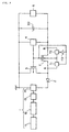
- Figure 1 is a block diagram showing a first embodiment of a power supply unit in an electronic timepiece of the present invention.
- Figure 2 is a block diagram showing a second embodiment of a power supply unit in an electronic timepiece of the present invention.
- Figure 3 is a block diagram showing an example of prior art for a power supply unit in a conventional electronic timepiece.
- Figure 4 is a block diagram showing another example of prior art for a power supply unit in a conventional electronic timepiece.
- Figure 1 is a block diagram of a power supply unit in an electronic timepiece corresponding to a first embodiment of the present invention. The same parts as in Figure 3 are described by the same symbols.
- a diode which withstands a high voltage is used as a diode 2 and is connected between a power generating section 1 and a battery section 30, a voltage detecting section 4, and an overcharging preventive section 5.
- This structure is so designed that an extremely high voltage which is suddenly generated by the mechanical power generating section 1 is never applied to the voltage detecting section 4 and the overcharging preventive section 5. Therefore, it is unnecessary to use devices which withstand high voltage for the voltage detecting section 4 and the overcharging preventive section 5, thereby reducing the costs.
- a secondary battery such as titanium-lithium ion secondary battery or the like having a comparatively large internal resistance and a large capacity is used as the battery section 30.
- a switching transistor composed of a NMOS transistor or the like is installed as a reverse current preventive section 7. Specifically, a switching transistor having an inverse function to that of a PMOS transistor for the overcharging preventive section 5 is used.
- the voltage detecting section 4 outputs a signal at an "H" level when the potential of the secondary battery forming the battery section 30 is below the prescribed voltage (for example, 2.5 V). In this condition, the reverse current preventive section 7 is on and the overcharging preventive section 5 is off so that the power generated by the power generating section 1 is charged in the secondary battery.
- the prescribed voltage for example, 2.5 V
- the potential of the secondary battery exceeds 2.5 V and then the voltage detecting section 4 outputs a signal at an "H" level.
- the overcharging preventive section 5 is on and, at the same time, the reverse current preventive section 7 is off.
- the current generated by the power generating section 1 is discharged by the overcharging preventive section 5 and is not charged to the secondary battery.
- the reverse current preventive section 7 is off, the overcharging preventive section 5 is never connected electrically with the secondary battery whereby a voltage drop across the secondary battery is avoided.
- the reverse current preventive section 7 composed of a switching transistor, which is off while the overcharging preventive section 5 is discharging, is installed between the overcharging preventive section 5 and the secondary battery. Therefore, a voltage drop across the secondary battery never appears during the discharge from the overcharging preventive section 5 and hence a stable discharge action is attained until the potential of the secondary battery is below 2.5 V. It is apparent from the above explanation that the power supply unit corresponding to this embodiment is efficiently used in electronic timepieces such as an electronic wrist timepiece provided with an overcharging preventive section, especially in the case where the resistance of the action of the overcharging preventive section is of the same order as the internal resistance of the battery section.
- the switching transistors having inverse functions are used as the overcharging preventive section 5 and the reverse current preventive section 7 respectively and these transistors are allowed to function inversely at the same time by one signal from the voltage detecting section 4 so that the action is accurate and the circuit structure is simple.
- Figure 2 is a block diagram showing a power supply unit in an electronic timepiece of a second embodiment of the present invention.
- a plurality of switching means 71 and 72 which are both turned on when a control terminal C reaches the "H" level are respectively connected between a substrate and a drain and between the substrate and a source of a NMOS transistor which constitutes a reverse current preventive section 7.
- the signal from a voltage detecting section 4 is directly input into the control terminal C of the switching means 71, and into the control terminal C of the switching means 72 after it is reversed by an inverter 73.
- the switching means 71 and 72 may be controlled so that the switching means 71 is on and the switching means 72 is off.
- the signal output from the potential detection section 4 is at the "H" level and hence the switching means 71 is on and the switching means 72 is off, whereby a normal operation is performed.
- the switching means 71 and 72 may be controlled so that the switching means 71 is off and the switching means 72 is on.
- the signal output from the voltage detecting section 4 is at the "L" level and hence the switching means 71 is off and the switching means 72 is on, whereby a normal operation is performed.
- the switching transistor of the reverse current preventive section 7 is allowed to function without fail.
- the power supply unit of the present invention for an electronic timepiece is suitable for power supplies for electronic timepieces such as an electronic wrist watch or the like.
Landscapes
- Engineering & Computer Science (AREA)
- Power Engineering (AREA)
- Physics & Mathematics (AREA)
- General Physics & Mathematics (AREA)
- Electromechanical Clocks (AREA)
- Electric Clocks (AREA)
- Charge And Discharge Circuits For Batteries Or The Like (AREA)
Applications Claiming Priority (4)
| Application Number | Priority Date | Filing Date | Title |
|---|---|---|---|
| JP5524696 | 1996-03-13 | ||
| JP55246/96 | 1996-03-13 | ||
| JP5524696 | 1996-03-13 | ||
| PCT/JP1997/000787 WO1997034355A1 (fr) | 1996-03-13 | 1997-03-12 | Bloc d'alimentation pour pieces d'horlogerie electroniques |
Publications (3)
| Publication Number | Publication Date |
|---|---|
| EP0836263A1 true EP0836263A1 (fr) | 1998-04-15 |
| EP0836263A4 EP0836263A4 (fr) | 2000-05-10 |
| EP0836263B1 EP0836263B1 (fr) | 2005-05-04 |
Family
ID=12993249
Family Applications (1)
| Application Number | Title | Priority Date | Filing Date |
|---|---|---|---|
| EP97907295A Expired - Lifetime EP0836263B1 (fr) | 1996-03-13 | 1997-03-12 | Bloc d'alimentation pour pieces d'horlogerie electroniques |
Country Status (5)
| Country | Link |
|---|---|
| US (1) | US5881028A (fr) |
| EP (1) | EP0836263B1 (fr) |
| JP (1) | JP3718725B2 (fr) |
| DE (1) | DE69733181T2 (fr) |
| WO (1) | WO1997034355A1 (fr) |
Cited By (1)
| Publication number | Priority date | Publication date | Assignee | Title |
|---|---|---|---|---|
| EP1006640A2 (fr) * | 1998-12-04 | 2000-06-07 | Seiko Epson Corporation | Dispositif électronique portatif et méthode de commande du dispositif électronique portatif |
Families Citing this family (5)
| Publication number | Priority date | Publication date | Assignee | Title |
|---|---|---|---|---|
| JP2005525169A (ja) * | 2002-05-10 | 2005-08-25 | コーディス・コーポレイション | 一定の構造フレームの上に一定の薄い壁部の管状の膜を有する医療装置を作成する方法 |
| JP4978283B2 (ja) * | 2007-04-10 | 2012-07-18 | セイコーエプソン株式会社 | モータ駆動制御回路、半導体装置、電子時計および発電装置付き電子時計 |
| JP2010164458A (ja) * | 2009-01-16 | 2010-07-29 | Casio Computer Co Ltd | 電子時計 |
| JP6389622B2 (ja) * | 2014-03-07 | 2018-09-12 | 旭化成エレクトロニクス株式会社 | 過充電防止回路 |
| US9703268B2 (en) * | 2015-09-11 | 2017-07-11 | Lenovo (Singapore) Pte. Ltd. | Gauge opacity control |
Citations (5)
| Publication number | Priority date | Publication date | Assignee | Title |
|---|---|---|---|---|
| US4054826A (en) * | 1975-03-10 | 1977-10-18 | Wahlstrom Sven E | Method and apparatus for charging batteries using variable capacitors |
| EP0326312A2 (fr) * | 1988-01-25 | 1989-08-02 | Seiko Epson Corporation | Montre bracelet électronique |
| US5001685A (en) * | 1988-01-25 | 1991-03-19 | Seiko Epson Corporation | Electronic wristwatch with generator |
| EP0679969A2 (fr) * | 1994-04-27 | 1995-11-02 | Seiko Epson Corporation | Pièce d'horlogerie à indication analogique et méthode de charge de celle-ci |
| EP0685777A2 (fr) * | 1994-05-13 | 1995-12-06 | Seiko Epson Corporation | Montre électronique et méthode pour son chargement |
Family Cites Families (5)
| Publication number | Priority date | Publication date | Assignee | Title |
|---|---|---|---|---|
| JPS5232374A (en) * | 1975-09-08 | 1977-03-11 | Citizen Watch Co Ltd | Electronic watch |
| JPS52114933A (en) * | 1976-03-23 | 1977-09-27 | Suwa Seikosha Kk | Control circuit for charging |
| JPS6159911A (ja) * | 1984-08-30 | 1986-03-27 | Nec Corp | 切換スイツチ回路 |
| DE69514056T2 (de) * | 1994-03-29 | 2000-06-08 | Citizen Watch Co., Ltd. | Stromversorgungsgerät für elektrische apparate |
| JP3120204B2 (ja) * | 1994-07-25 | 2000-12-25 | セイコーインスツルメンツ株式会社 | 電子制御時計 |
-
1997
- 1997-03-12 EP EP97907295A patent/EP0836263B1/fr not_active Expired - Lifetime
- 1997-03-12 US US08/945,745 patent/US5881028A/en not_active Expired - Lifetime
- 1997-03-12 JP JP53244397A patent/JP3718725B2/ja not_active Expired - Fee Related
- 1997-03-12 WO PCT/JP1997/000787 patent/WO1997034355A1/fr active IP Right Grant
- 1997-03-12 DE DE69733181T patent/DE69733181T2/de not_active Expired - Fee Related
Patent Citations (5)
| Publication number | Priority date | Publication date | Assignee | Title |
|---|---|---|---|---|
| US4054826A (en) * | 1975-03-10 | 1977-10-18 | Wahlstrom Sven E | Method and apparatus for charging batteries using variable capacitors |
| EP0326312A2 (fr) * | 1988-01-25 | 1989-08-02 | Seiko Epson Corporation | Montre bracelet électronique |
| US5001685A (en) * | 1988-01-25 | 1991-03-19 | Seiko Epson Corporation | Electronic wristwatch with generator |
| EP0679969A2 (fr) * | 1994-04-27 | 1995-11-02 | Seiko Epson Corporation | Pièce d'horlogerie à indication analogique et méthode de charge de celle-ci |
| EP0685777A2 (fr) * | 1994-05-13 | 1995-12-06 | Seiko Epson Corporation | Montre électronique et méthode pour son chargement |
Non-Patent Citations (1)
| Title |
|---|
| See also references of WO9734355A1 * |
Cited By (4)
| Publication number | Priority date | Publication date | Assignee | Title |
|---|---|---|---|---|
| EP1006640A2 (fr) * | 1998-12-04 | 2000-06-07 | Seiko Epson Corporation | Dispositif électronique portatif et méthode de commande du dispositif électronique portatif |
| EP1006640A3 (fr) * | 1998-12-04 | 2001-03-28 | Seiko Epson Corporation | Dispositif électronique portatif et méthode de commande du dispositif électronique portatif |
| US6424600B1 (en) | 1998-12-04 | 2002-07-23 | Seiko Epson Corporation | Portable electronic device and control method for controlling the portable electronic device |
| CN100430843C (zh) * | 1998-12-04 | 2008-11-05 | 精工爱普生株式会社 | 携带式电子设备及携带式电子设备控制方法 |
Also Published As
| Publication number | Publication date |
|---|---|
| DE69733181T2 (de) | 2006-02-16 |
| JP3718725B2 (ja) | 2005-11-24 |
| EP0836263B1 (fr) | 2005-05-04 |
| WO1997034355A1 (fr) | 1997-09-18 |
| DE69733181D1 (de) | 2005-06-09 |
| US5881028A (en) | 1999-03-09 |
| EP0836263A4 (fr) | 2000-05-10 |
Similar Documents
| Publication | Publication Date | Title |
|---|---|---|
| KR102285228B1 (ko) | 이차전지 보호 회로, 이차전지 보호 장치, 전지 팩 및 이차전지 보호 회로의 제어 방법 | |
| KR101035541B1 (ko) | 전지보호 장치, 및, 그것을 이용한 전지보호 시스템, 및,전지보호 방법 | |
| JP3324930B2 (ja) | 電源装置 | |
| US6316915B1 (en) | Charge/discharge protection circuit and battery pack having the charge/discharge protection circuit | |
| KR100907360B1 (ko) | 배터리 상태 감시회로 및 배터리 장치 | |
| US7710076B2 (en) | Back-gate voltage generator circuit, four-terminal back gate switching FET, and charge and discharge protection circuit using same | |
| EP1056190B1 (fr) | Dispositif d'alimentation, procede d'alimentation, dispositif electronique portatif et montre electronique | |
| KR100981031B1 (ko) | 충전/방전 보호 회로 | |
| JPH0767263A (ja) | 二次電池の過放電防止回路 | |
| WO1989006834A1 (fr) | Montre electronique pourvue d'un generateur de courant | |
| EP0467667B1 (fr) | Circuit d'alimentation pour appareillages électroniques | |
| US5881028A (en) | Power supply for electronic timepiece | |
| EP1411615B1 (fr) | Dispositif de charge d'une dynamo de bicyclette | |
| KR20020079366A (ko) | 전압 변환 장치 | |
| US4672289A (en) | Circuit configuration incorporating an A.C.-fed load connected in series with a capacitor unit | |
| GB2159351A (en) | Charge/discharge circuit | |
| US5684681A (en) | Drive circiut of switching element for switching mode power supply device | |
| EP0996211B1 (fr) | Appareil portatif électronique | |
| JP2007110855A (ja) | 充電装置 | |
| JP3801164B2 (ja) | 電池パック | |
| JPH10210681A (ja) | 電力制御装置およびこれを備えた電子機器 | |
| JP2021158752A (ja) | 充放電制御装置及びバッテリ装置 | |
| JP2956483B2 (ja) | 過充電防止装置 | |
| JPH10201128A (ja) | 電力制御装置およびこれを備えた電子機器 | |
| KR100308530B1 (ko) | 배터리의 충방전 제어회로 |
Legal Events
| Date | Code | Title | Description |
|---|---|---|---|
| PUAI | Public reference made under article 153(3) epc to a published international application that has entered the european phase |
Free format text: ORIGINAL CODE: 0009012 |
|
| 17P | Request for examination filed |
Effective date: 19971114 |
|
| AK | Designated contracting states |
Kind code of ref document: A1 Designated state(s): CH DE LI |
|
| A4 | Supplementary search report drawn up and despatched |
Effective date: 20000328 |
|
| AK | Designated contracting states |
Kind code of ref document: A4 Designated state(s): CH DE LI |
|
| RAP1 | Party data changed (applicant data changed or rights of an application transferred) |
Owner name: CITIZEN WATCH CO. LTD. |
|
| 17Q | First examination report despatched |
Effective date: 20040105 |
|
| GRAP | Despatch of communication of intention to grant a patent |
Free format text: ORIGINAL CODE: EPIDOSNIGR1 |
|
| GRAS | Grant fee paid |
Free format text: ORIGINAL CODE: EPIDOSNIGR3 |
|
| GRAA | (expected) grant |
Free format text: ORIGINAL CODE: 0009210 |
|
| AK | Designated contracting states |
Kind code of ref document: B1 Designated state(s): CH DE LI |
|
| REG | Reference to a national code |
Ref country code: CH Ref legal event code: EP |
|
| REF | Corresponds to: |
Ref document number: 69733181 Country of ref document: DE Date of ref document: 20050609 Kind code of ref document: P |
|
| REG | Reference to a national code |
Ref country code: CH Ref legal event code: NV Representative=s name: ISLER & PEDRAZZINI AG |
|
| PLBE | No opposition filed within time limit |
Free format text: ORIGINAL CODE: 0009261 |
|
| STAA | Information on the status of an ep patent application or granted ep patent |
Free format text: STATUS: NO OPPOSITION FILED WITHIN TIME LIMIT |
|
| 26N | No opposition filed |
Effective date: 20060207 |
|
| REG | Reference to a national code |
Ref country code: CH Ref legal event code: PCAR Free format text: ISLER & PEDRAZZINI AG;POSTFACH 1772;8027 ZUERICH (CH) |
|
| REG | Reference to a national code |
Ref country code: CH Ref legal event code: PFA Owner name: CITIZEN HOLDINGS CO., LTD. Free format text: CITIZEN WATCH CO. LTD.#1-12, TANASHICHO 6-CHOME, NISHITOKYO-SHI#TOKYO 188-8511 (JP) -TRANSFER TO- CITIZEN HOLDINGS CO., LTD.#1-12, TANASHICHO 6-CHOME#NISHITOKYO-SHI, TOKYO 188-8511 (JP) |
|
| PGFP | Annual fee paid to national office [announced via postgrant information from national office to epo] |
Ref country code: CH Payment date: 20090317 Year of fee payment: 13 |
|
| PGFP | Annual fee paid to national office [announced via postgrant information from national office to epo] |
Ref country code: DE Payment date: 20090306 Year of fee payment: 13 |
|
| REG | Reference to a national code |
Ref country code: CH Ref legal event code: PL |
|
| PG25 | Lapsed in a contracting state [announced via postgrant information from national office to epo] |
Ref country code: LI Free format text: LAPSE BECAUSE OF NON-PAYMENT OF DUE FEES Effective date: 20100331 Ref country code: DE Free format text: LAPSE BECAUSE OF NON-PAYMENT OF DUE FEES Effective date: 20101001 Ref country code: CH Free format text: LAPSE BECAUSE OF NON-PAYMENT OF DUE FEES Effective date: 20100331 |