EP1006493B1 - Automatische Transaktionsvorrichtung - Google Patents
Automatische Transaktionsvorrichtung Download PDFInfo
- Publication number
- EP1006493B1 EP1006493B1 EP99305524A EP99305524A EP1006493B1 EP 1006493 B1 EP1006493 B1 EP 1006493B1 EP 99305524 A EP99305524 A EP 99305524A EP 99305524 A EP99305524 A EP 99305524A EP 1006493 B1 EP1006493 B1 EP 1006493B1
- Authority
- EP
- European Patent Office
- Prior art keywords
- scanner
- lid
- transaction
- user
- power failure
- Prior art date
- Legal status (The legal status is an assumption and is not a legal conclusion. Google has not performed a legal analysis and makes no representation as to the accuracy of the status listed.)
- Expired - Lifetime
Links
Images



Classifications
-
- G—PHYSICS
- G07—CHECKING-DEVICES
- G07F—COIN-FREED OR LIKE APPARATUS
- G07F19/00—Complete banking systems; Coded card-freed arrangements adapted for dispensing or receiving monies or the like and posting such transactions to existing accounts, e.g. automatic teller machines
- G07F19/20—Automatic teller machines [ATMs]
-
- G—PHYSICS
- G07—CHECKING-DEVICES
- G07F—COIN-FREED OR LIKE APPARATUS
- G07F19/00—Complete banking systems; Coded card-freed arrangements adapted for dispensing or receiving monies or the like and posting such transactions to existing accounts, e.g. automatic teller machines
- G07F19/20—Automatic teller machines [ATMs]
- G07F19/201—Accessories of ATMs
Definitions
- the present invention relates to an automatic transaction apparatus for a financial institution, such as a bank, for performing transactions automatically, including deposit and withdrawal of money and opening of accounts, and in particular to a backup function for the automatic transaction apparatus in case of power failure.
- ATM Automatic teller machines
- finance institutions such as banks
- ATM Automatic teller machines
- the machine communicates with a host computer along a communication line, and automatically receives cash from the user or pays out cash to the user.
- the automatic transaction apparatus having the account opening function automatically performs predetermined account opening procedures upon receiving a request for the account opening from the user.
- the automatic transaction apparatus having an account opening function includes an image reader, i.e., a so-called scanner, to automatically perform those jobs.
- the user sets the transaction media (the application form and the identification) on the scanner, and the scanner then scans them to obtain information concerning the contents of the transaction media.
- US 5,774,663 discloses an apparatus according to the preamble of accompanying claim 1. There is no disclosure concerning actions to be taken in the event of a power failure.
- a flat bed scanner which is currently the most popular, can be expected to be used as the image reader.
- the flat bed scanner has a two-dimensional scanner face, and an attached top lid which-the user must open in order to set the application form or the identification on the scanner face.
- the scanner face must be prevented from becoming dirty and from being scratched.
- the automatic transaction apparatus must be secured, since one which is used by the public is often'in danger of being abused or of being damaged on purpose.
- a locking mechanism is provided for the lid, and the lid is normally maintained in a locked state in order to prevent unwanted contact with the scanner face. That is, the lid is unlocked only to set an identification on the scanner face, to remove the identification from the scanner face, and to set the application form on the scanner face. Since the identification must be returned to the user, the lid is unlocked after the identification has been scanned. However, since after the application form has been scanned it is fed into the automatic transaction apparatus, the lid is not unlocked after the application scanning process has been completed. Also, when the application form or the identification is set on the scanner and the lid is closed, the lid is immediately locked in order to prevent it from being opened by mistake during the scanning process.
- an urgent requirement is that the lid of a scanner be unlocked when the power failure occurs while a transaction medium which must be returned to the user (e.g. identification) is set for scanning.
- a transaction medium which must be returned to the user e.g. identification
- the lid need not be unlocked because a transaction medium which does not have to be returned to the user (e.g. application form) is set for scanning.
- an automatic transaction apparatus which can control the locking and the unlocking of the lid of a scanner in accordance with the type of the transaction media set on the scanner.
- an automatic transaction apparatus comprising: a receiver for receiving a plurality of types of transaction media in accordance with transaction procedures; a power failure detector for detecting a power failure; and a controller for determining whether a transaction medium is to be returned in accordance with the type of transaction medium which has been received by the receiver when the power failure is detected by the power failure detector, and for enabling the receiver to return the transaction medium only in the case that the transaction medium is to be returned, wherein the receiver includes a backup power source, and when the power failure is detected, the controller enables the receiver to return the transaction medium in the case that the transaction medium is to be returned by using the backup power source.
- the receiver may include a locking mechanism for normally locking the receiver and for unlocking the receiver during receiving and returning the transaction medium; and in case that a power failure is detected and the transaction medium received by the receiver is to be returned, the controller unlocks the locking mechanism in order to enable the receiver to return the transaction medium. At this time, the locking mechanism is unlocked by power received from the backup power source.
- the locked state of the receiver is maintained, even when a power failure occurs.
- the unlocked state of the receiver is reduced to the minimum, and this helps to protect the apparatus and to prevent it from being intentionally damaged or destroyed.
- the transaction medium set in the receiver is one that should be returned to the user (e.g., an identification)
- the backup power source internally provided for the receiver is used to unlock the receiver, so that the transaction medium can be returned.
- Fig. 1 is a schematic, perspective view of an automatic transaction apparatus according to one embodiment of the present invention.
- Fig. 2 is a block diagram of the automatic transaction apparatus in Fig. 1. While referring to Figs. 1 and 2, an explanation will now be given for a case where the user deposits or withdraws cash by using the automatic transaction apparatus.
- the user manipulates an operating unit 2, whereon number keys, etc., are provided, in accordance with predetermined instructions displayed on the screen of a monitor 1 in Fig. 1, and selects either the deposit or the withdrawal of cash.
- the transaction procedures for depositing cash, for withdrawing cash, and for opening a new account which will be described later, are stored as programs in the memory of a controller 10 in Fig. 2, and the CPU of the controller 10 executes a corresponding program when performing these procedures.
- the user inserts his or her bankbook or bank card into either a bankbook slot 3 or a card slot 4.
- the automatic transaction apparatus then employs an internally provided magnetic strip reading unit 11 (see Fig. 2) to read information, such as the account number of the user, from the magnetic strip attached to the bankbook or to the bank card.
- an internally provided magnetic strip reading unit 11 see Fig. 2
- the user places the cash in a cash port 5, and thereafter a cash handling unit 12 (see Fig. 2) inside the automatic transaction apparatus secures and counts the cash.
- the controller 10 which communicates on-line with a host computer, then transmits to the host computer information concerning the transaction, including the account number of the user and the amount of cash which was received, and initiates the internal process which is performed for a cash deposit.
- a bankbook entering unit 13 When the bankbook has been inserted, after the process has been completed the amount of the deposit is recorded in the bankbook by a bankbook entering unit 13, and the bankbook is returned to the user via the bankbook slot 3.
- a receipt issuing unit 14 prepares a transaction receipt which is discharged through a receipt port 6, and the bank card is returned to the user via the card slot 4.
- the user inserts either the bankbook or the bank card, and uses the operating unit 2 to enter an identification number and the amount of money to be withdrawn.
- the controller 10 (see Fig. 2) communicates on-line with the host computer, to which it transmits information, including the account number of the user and the amount of money to be withdrawn, and initiates the process which is performed for a cash withdrawal.
- the cash handling unit 12 extracts from a cash storage unit in the automatic transaction apparatus an amount in cash equivalent to the amount of the requested withdrawal, and discharges the cash through the cash port 5.
- the user receives the cash and also the bankbook or a receipt and the bank card.
- the automatic transaction apparatus in this embodiment includes an image reader (scanner) 15 which is used when executing the account opening process.
- Fig. 3 is a partial top view of the image reader 15.
- the image reader 15 is a so-called flatbed scanner.
- the user opens a lid 151, sets predetermined transaction media (papers, card, etc), which will be described later, on a scanner face 152, and closes the lid 151.
- a solenoid locking mechanism which includes lock levers 153 and 154 and a solenoid 155, is provided for the lid 151, as will be described later in detail, and normally locks the lid 151 to prevent it from being opened unnecessarily.
- the lid 151 is unlocked when it is necessary for a specific medium to be set on the scanner face 152 during the account opening process, which will be described later, or when the user should remove the medium from the scanner face 152.
- a top view of the solenoid locking mechanism in the unlocked state is used for explaining the operation of the solenoid locking mechanism.
- a solenoid 155 is provided with a permanent magnet and is a self-maintaining solenoid which can maintain its current state at the time the supply of a current is stopped.
- a linking member 156 which is connected to the lock lever 153, is attracted by the solenoid 155 in direction A.
- the lock lever 153 moves in direction a
- the lock lever 154 also moves in direction a via another linking member 157, which is connected to the linking member 156.
- engagement portions (not shown), which are provided for a frame 158 on the side of the image reader, are engaged with the lock levers 153 and 154, and a locked state is provided wherein the lid 151 can not be opened. Then, when a current flowing in the direction opposite that of the predetermined direction is supplied to the solenoid 155, the polarity of the solenoid 155 is inverted, and the solenoid 155 drives the linking members 156 and 157 in direction B. Accordingly, the lock levers 153 and 154 move in direction b, and are disengaged from the frame 158, providing the unlocked state.
- the solenoid 155 is a self-maintained type, the supply of a current to the solenoid 155 is stopped once the polarity of the solenoid 155 has been changed.
- the supply of a current to the solenoid 155, and the direction of the current which must be supplied in order to change the polarity of the solenoid 155 are controlled by the controller 10 in accordance with the progress of the transaction procedures.
- Fig. 5 is a flowchart showing the transaction process performed when a new account is opened.
- the user desires to open a new account, he or she manipulates the operating panel 2 and selects an account opening transaction displayed on the first selection screen of the monitor 1 (step S1).
- the lid 151 of the image reader 15 is unlocked (step S2).
- the user then opens the lid 151 of the image reader 15, and set his or her identification on the scanner face 152 of the image reader 15 (step S3).
- the solenoid locking mechanism of the lid 151 is activated and locks the lid 151 (step S4).
- the image reading (scanning) process is performed (step S5).
- the solenoid locking mechanism releases the lid 151 from the locked state (step S6), and the user opens the lid 151 and removes the identification (step S7).
- the lid 151 continues to be maintained in the unlocked state.
- an application form issuing unit 16 in the automatic transaction apparatus prints an account opening application form and discharges it through an application form port 7 (see Fig. 1).
- the user writes required information, such as his or her name and address (step S8).
- the user When the user has finished filling out the application form, he or she opens the lid 151 of the image reader 15, and sets the application form on the scanner face 152 (step S9).
- the lid 151 After the lid 151 has been closed, it is locked by the solenoid locking mechanism (step S10) and the application form is scanned (step S11).
- the application form is fed into the automatic transaction apparatus by feeding rollers 159 provided for the image reader 15 (step S12).
- the bankbook issuing unit 17 and the card issuing unit 18 create a bankbook and a bank card, and discharge them through the bankbook slot 3 and the card slot 4 (step S13). After the user has received the bankbook and the bank card, the transaction is terminated.
- the lid 151 of the image reader 15 is kept locked. It is for preventing the lid 151 from being opened by mistake during the scanning, so that a normal scanning process can be performed.
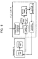
- Fig. 6 is a block diagram of an arrangement for the electrical control of the image reader 15, and Fig. 7 is a signal timing chart for the individual components shown in Fig. 6.
- a backup power source 20 constituted by, for example, a large capacitor. The discharge by the backup power source 20 of a current which is supplied to the solenoid locking mechanism 21 is triggered by its receipt of a drive signal from a control logic circuit 25.
- the solenoid locking mechanism 21 receives a current from a power source (not shown), and locks or unlocks the lid 151 in accordance with control signals from the controller 10.
- a CPU 100 in the controller 10 sets the image reader 15 to the unlocked state at step S2 of the flowchart in Fig. 5.
- a lid state detector 22 When the lid 151 is unlocked and is opened by the user, its state is detected by a lid state detector 22, a circuit for detecting the open/closed state of the lid 151.
- the lid state detector 22 When the lid 151 is closed, the lid state detector 22 is rendered conductive, and it transmits a lid closed signal to the CPU 100.
- the lid state detector 22 When the lid 151 is opened, the lid state detector 22 is not rendered conductive, and does not transmit a signal. As is shown in Fig. 7A, therefore, when the transmission of the lid closed signal from the lid state detector 22 is temporarily stopped and then is restarted, from this the CPU 100 ascertains that an identification have been set by opening the lid 151, and that the lid 151 has been closed. The CPU 100 then locks the lid 151 and activates the image reader 15.
- the CPU 100 transmits a pulse signal P1 to a latch circuit 23.
- the latch circuit 23 changes an output signal level from level L to level H, and maintains that output level until the next pulse signal P2 is received. Therefore, as is shown in Fig. 7C, upon receiving the pulse signal P1, which the CPU 100 outputs at the same time as it locks the lid 151, the output level of the latch circuit 23 is changed to level H.
- the CPU 100 unlocks the lid 151, and also transmits a pulse signal P2 to the latch circuit 23.
- the output signal level of the latch circuit 23 is then returned to level L.
- the state of the latch circuit 23 is stored in the memory 101, and is maintained so that the latch circuit 23 is changed to level L when the account opening process is started.
- the state of the lid 151 is also stored in the memory 101.
- a output signal from the latch circuit 23 is transmitted to a control logical circuit 25.
- the control logical circuit 25 also receives a monitor signal from a power voltage monitoring circuit 24.
- the power voltage monitoring circuit 24 compares the power voltage with a predetermined reference voltage Vref. When the power voltage is brought lower than the reference voltage Vref due to the occurrence of the power failure, the monitor signal is changed from level L to level H, as is shown in Fig. 7E. When both the signal from the latch circuit 23 and.the monitor signal from the power voltage monitoring circuit 24 are changed to level H, as is shown in Fig.
- the control logical circuit 25 outputs a conductive signal at level H based on the logical product (AND) of the two signals, so that the backup power source 20 and the solenoid locking mechanism 21 are rendered conductive. Then, a current is supplied to the solenoid locking mechanism 21.
- the backup power source 20 is so set in advance that the current is supplied in the direction in which the solenoid locking mechanism 21 is unlocked. Thus, the locked state is changed to the unlocked state.
- the CPU 100 Ascertains that the transmission of the lid closed signal from the lid state detector 22 has been stopped and restarted, and the lid 151 is locked. However, at this time, the CPU 100 does not transmit to the latch circuit 23 the pulse signal P1 shown in Fig. 7B. Therefore, the output signal from the latch circuit 23 in Fig. 7C is maintained at level L. And even when, upon the occurrence of the power failure, the monitor signal at level H is transmitted by the power voltage monitoring circuit 24 to the control logical circuit 25, the control logical circuit 25 does not output a conductive signal at level H based on the logical product (AND) of the two signals (see the broken line in Fig. 7F). Thus, even when the power failure occurs while the application form is being scanned, the backup power source 20 is not activated and the locked state is maintained.
- the locked state is maintained even when the power failure occurs during the scanning of the application form. Therefore, the unlocked state of the lid of the image reader can be reduced to the minimum, so that it will be protected from being damaged or destroyed.
- the backup power source 20 is activated only when the power failure occurs during scanning the medium which must be returned to the user, and the lid 151 must be unlocked so that the medium can be returned.
- the controller 10 notifies the image reader 15 in advance of a current condition (a locked state when an identification is located in the image reader) for which a backup operation could be required (the current condition is stored in the latch circuit by using pulse signal P1 from the CPU 100). Therefore, a backup device is not required for the automatic transaction apparatus, and even when the controller 10 is disabled due to the power failure, a required backup operation can be performed.
- the transaction medium which must be set on the scanner face are not limited to an application form and an identification; during the account opening process other media may be required to be submitted.
- the transactions which may be executed by the automatic transaction apparatus are not limited to account transactions.
- the automatic transaction apparatus will request the transaction media which are required, and in accordance with whether requested media must be returned to the user, will perform the above operation when the power failure occurs.
- the apparatus to be used to receive the transaction media from the user is not limited to the image reader in this embodiment; any apparatus can be employed so long as it can receive predetermined transaction media from the user and so long as it includes a locking mechanism.
- the unlocked state of the receiver can be reduced to the minimum in order to prevent it from being damaged or destroyed.
- the backup power source provided for the receiver is activated to unlock the receiver, so that the medium can be returned.
Landscapes
- Business, Economics & Management (AREA)
- Accounting & Taxation (AREA)
- Finance (AREA)
- Physics & Mathematics (AREA)
- General Physics & Mathematics (AREA)
- Financial Or Insurance-Related Operations Such As Payment And Settlement (AREA)
- Control Of Vending Devices And Auxiliary Devices For Vending Devices (AREA)
Claims (2)
- Automatische Transaktionsvorrichtung mit
einem Scanner (15) zum Empfangen einer Vielzahl von Typen von Transaktionsmedien gemäß Transaktionsprozeduren,
gekennzeichnet durch
einem Stromausfalldetektor (24) zum Detektieren eines Stromausfalls, und
einem Controller (10) zum Bestimmen, ob ein Transaktionsmedium zurückgeführt werden soll, entsprechend dem Typ des Transaktionsmediums, das von dem Scanner empfangen wurde, als der Stromausfall durch den Stromausfalldetektor detektiert wurde, um dem Scanner zu ermöglichen, das Transaktionsmedium nur in dem Fall zurückzuführen, wenn das Transaktionsmedium zurückgeführt werden muß,
worin der Scanner (15) eine Scanner-Ersatzstromquelle (20) enthält,
einen Verriegelungsmechanismus, um normaler Weise den Scanner zu verriegeln und zu entriegeln während des Empfangens und des Rückführens des Transaktionsmediums zu verriegeln und zu entriegeln;
und falls ein Stromausfall detektiert wird und das von dem Scanner empfangene Transaktionsmedium zurückzuführen ist, der Controller (10) den Verriegelungsmechanismus entriegelt, um dem Scanner zu ermöglichen, das Transaktionsmedium zurückzuführen, unter Verwendung der Ersatzstromquelle. - Automatische Transaktionsvorrichtung nach Anspruch 1, bei weicher der Scanner (15) einen Deckel (151) umfaßt, der den verriegelungsmechanismus und einen Hauptkörper enthält, wobei der Verriegelungsmechnismus ein Solenoid (155) und einen Hebel (153, 154) enthält, der mit dem Solenoid verbunden ist,
und er Hebel sich gemäß einer Änderung der Polarität des Solenoids bewegt, um durch Eingriff mit dem Hauptkörper einen Verriegelungszustand herzustellen.
Applications Claiming Priority (2)
| Application Number | Priority Date | Filing Date | Title |
|---|---|---|---|
| JP34294698 | 1998-12-02 | ||
| JP10342946A JP2000172900A (ja) | 1998-12-02 | 1998-12-02 | 自動取引装置 |
Publications (3)
| Publication Number | Publication Date |
|---|---|
| EP1006493A2 EP1006493A2 (de) | 2000-06-07 |
| EP1006493A3 EP1006493A3 (de) | 2001-06-20 |
| EP1006493B1 true EP1006493B1 (de) | 2004-04-07 |
Family
ID=18357748
Family Applications (1)
| Application Number | Title | Priority Date | Filing Date |
|---|---|---|---|
| EP99305524A Expired - Lifetime EP1006493B1 (de) | 1998-12-02 | 1999-07-12 | Automatische Transaktionsvorrichtung |
Country Status (4)
| Country | Link |
|---|---|
| US (1) | US6457133B1 (de) |
| EP (1) | EP1006493B1 (de) |
| JP (1) | JP2000172900A (de) |
| ES (1) | ES2218954T3 (de) |
Families Citing this family (4)
| Publication number | Priority date | Publication date | Assignee | Title |
|---|---|---|---|---|
| DE10041133C2 (de) * | 2000-08-21 | 2003-08-28 | Com Design Gmbh | Möbel für die Selbstbedienung |
| US6850730B2 (en) * | 2003-05-22 | 2005-02-01 | Xerox Corporation | Platen cover positioning system for an input scanner or copier |
| JP4378493B2 (ja) * | 2007-04-27 | 2009-12-09 | シャープ株式会社 | 画像形成装置 |
| CN106786853A (zh) * | 2016-12-02 | 2017-05-31 | 杭州创睿新能源科技有限公司 | 一种充电桩掉电解锁电路 |
Family Cites Families (11)
| Publication number | Priority date | Publication date | Assignee | Title |
|---|---|---|---|---|
| US3868648A (en) * | 1973-07-05 | 1975-02-25 | Ind Dynamics Inc | Programmable process and production control systems |
| US4142620A (en) * | 1977-10-11 | 1979-03-06 | Massachusetts Bay Transportation Authority | Access control system |
| JPS60153363U (ja) | 1984-03-16 | 1985-10-12 | オムロン株式会社 | カ−ドリ−ダ |
| JPS614257U (ja) | 1984-06-11 | 1986-01-11 | オムロン株式会社 | カ−ドリ−ダ |
| JPH02216598A (ja) | 1989-02-17 | 1990-08-29 | Oki Electric Ind Co Ltd | 自動取引装置の取引処理方法 |
| JP3431244B2 (ja) | 1993-12-01 | 2003-07-28 | 株式会社東芝 | 自動取引装置 |
| JPH08227329A (ja) | 1995-02-21 | 1996-09-03 | Hitachi Ltd | システム装置 |
| US5774663A (en) | 1995-09-05 | 1998-06-30 | Huntington Bancshares, Inc. | Personal banker customer management system providing interactive video communication in real time concerning banking information |
| US5679945A (en) * | 1995-03-31 | 1997-10-21 | Cybermark, L.L.C. | Intelligent card reader having emulation features |
| US6149064A (en) * | 1998-03-06 | 2000-11-21 | Kabushiki Kaisha Sankyo Seiki Seisakusho | IC card reader |
| US6254005B1 (en) * | 1999-06-03 | 2001-07-03 | Qi Technologies Corp. | Card reader with card capture clamp |
-
1998
- 1998-12-02 JP JP10342946A patent/JP2000172900A/ja active Pending
-
1999
- 1999-07-06 US US09/348,070 patent/US6457133B1/en not_active Expired - Fee Related
- 1999-07-12 ES ES99305524T patent/ES2218954T3/es not_active Expired - Lifetime
- 1999-07-12 EP EP99305524A patent/EP1006493B1/de not_active Expired - Lifetime
Also Published As
| Publication number | Publication date |
|---|---|
| US6457133B1 (en) | 2002-09-24 |
| ES2218954T3 (es) | 2004-11-16 |
| JP2000172900A (ja) | 2000-06-23 |
| EP1006493A2 (de) | 2000-06-07 |
| EP1006493A3 (de) | 2001-06-20 |
Similar Documents
| Publication | Publication Date | Title |
|---|---|---|
| JP5047257B2 (ja) | 自動取引処理装置、および自動取引処理システム | |
| JPH09223209A (ja) | カード読取機装置及び方法 | |
| US6176423B1 (en) | Shutter device having linkage which locks shutter as well as opens and closes the same | |
| US6457133B1 (en) | Automatic transaction apparatus | |
| JP2007323517A (ja) | 自動取引装置 | |
| EP0822525A2 (de) | Diebstahlsicherungssystem für Selbstbedienungsterminal | |
| JPH06119525A (ja) | 現金自動取引機の管理方法 | |
| JP2735810B2 (ja) | 自動カード発行機及びこれを用いたシステム | |
| JP5377427B2 (ja) | 現金自動取引装置、プログラムおよび取引方法 | |
| EP1544807A2 (de) | Verbesserte Transportkassette für Medien | |
| JP5433241B2 (ja) | 自動取引装置 | |
| CN100451912C (zh) | 用于卡型数据载体的读取设备及其操作方法和自助操作机 | |
| JPH0562050A (ja) | 現金取扱装置 | |
| JP2007087316A (ja) | 自動取引装置及び自動取引システム | |
| JP3431244B2 (ja) | 自動取引装置 | |
| JP2920231B2 (ja) | 解錠装置 | |
| JP2686578B2 (ja) | 自動取引装置 | |
| JPH11213214A (ja) | 電子錠管理システム | |
| JP2757459B2 (ja) | 自動取引き装置 | |
| JPH0883371A (ja) | 現金処理装置 | |
| JPH0448270B2 (de) | ||
| JP2023143456A (ja) | 自動取引装置および自動取引方法 | |
| JP3169766B2 (ja) | 自動販売機のロック装置 | |
| WO2024195620A1 (ja) | 媒体処理システム、媒体処理方法、および媒体処理プログラム | |
| KR20070066412A (ko) | 수표오방출 방지 금융자동화기기 및 그 동작방법 |
Legal Events
| Date | Code | Title | Description |
|---|---|---|---|
| PUAI | Public reference made under article 153(3) epc to a published international application that has entered the european phase |
Free format text: ORIGINAL CODE: 0009012 |
|
| AK | Designated contracting states |
Kind code of ref document: A2 Designated state(s): ES GB |
|
| AX | Request for extension of the european patent |
Free format text: AL;LT;LV;MK;RO;SI |
|
| PUAL | Search report despatched |
Free format text: ORIGINAL CODE: 0009013 |
|
| AK | Designated contracting states |
Kind code of ref document: A3 Designated state(s): AT BE CH CY DE DK ES FI FR GB GR IE IT LI LU MC NL PT SE |
|
| AX | Request for extension of the european patent |
Free format text: AL;LT;LV;MK;RO;SI |
|
| 17P | Request for examination filed |
Effective date: 20010627 |
|
| AKX | Designation fees paid |
Free format text: ES GB |
|
| 17Q | First examination report despatched |
Effective date: 20020226 |
|
| REG | Reference to a national code |
Ref country code: DE Ref legal event code: 8566 |
|
| GRAP | Despatch of communication of intention to grant a patent |
Free format text: ORIGINAL CODE: EPIDOSNIGR1 |
|
| GRAS | Grant fee paid |
Free format text: ORIGINAL CODE: EPIDOSNIGR3 |
|
| GRAA | (expected) grant |
Free format text: ORIGINAL CODE: 0009210 |
|
| AK | Designated contracting states |
Kind code of ref document: B1 Designated state(s): ES GB |
|
| REG | Reference to a national code |
Ref country code: GB Ref legal event code: FG4D |
|
| REG | Reference to a national code |
Ref country code: ES Ref legal event code: FG2A Ref document number: 2218954 Country of ref document: ES Kind code of ref document: T3 |
|
| PLBE | No opposition filed within time limit |
Free format text: ORIGINAL CODE: 0009261 |
|
| STAA | Information on the status of an ep patent application or granted ep patent |
Free format text: STATUS: NO OPPOSITION FILED WITHIN TIME LIMIT |
|
| 26N | No opposition filed |
Effective date: 20050110 |
|
| PGFP | Annual fee paid to national office [announced via postgrant information from national office to epo] |
Ref country code: GB Payment date: 20060712 Year of fee payment: 8 |
|
| PGFP | Annual fee paid to national office [announced via postgrant information from national office to epo] |
Ref country code: ES Payment date: 20060724 Year of fee payment: 8 |
|
| GBPC | Gb: european patent ceased through non-payment of renewal fee |
Effective date: 20070712 |
|
| PG25 | Lapsed in a contracting state [announced via postgrant information from national office to epo] |
Ref country code: GB Free format text: LAPSE BECAUSE OF NON-PAYMENT OF DUE FEES Effective date: 20070712 |
|
| REG | Reference to a national code |
Ref country code: ES Ref legal event code: FD2A Effective date: 20070713 |
|
| PG25 | Lapsed in a contracting state [announced via postgrant information from national office to epo] |
Ref country code: ES Free format text: LAPSE BECAUSE OF NON-PAYMENT OF DUE FEES Effective date: 20070713 |