EP1006036A2 - Federsystem für Schienenfahrzeug - Google Patents
Federsystem für Schienenfahrzeug Download PDFInfo
- Publication number
- EP1006036A2 EP1006036A2 EP99122820A EP99122820A EP1006036A2 EP 1006036 A2 EP1006036 A2 EP 1006036A2 EP 99122820 A EP99122820 A EP 99122820A EP 99122820 A EP99122820 A EP 99122820A EP 1006036 A2 EP1006036 A2 EP 1006036A2
- Authority
- EP
- European Patent Office
- Prior art keywords
- spring
- spring system
- sensor
- emergency support
- measuring
- Prior art date
- Legal status (The legal status is an assumption and is not a legal conclusion. Google has not performed a legal analysis and makes no representation as to the accuracy of the status listed.)
- Granted
Links
Images
Classifications
-
- B—PERFORMING OPERATIONS; TRANSPORTING
- B60—VEHICLES IN GENERAL
- B60G—VEHICLE SUSPENSION ARRANGEMENTS
- B60G17/00—Resilient suspensions having means for adjusting the spring or vibration-damper characteristics, for regulating the distance between a supporting surface and a sprung part of vehicle or for locking suspension during use to meet varying vehicular or surface conditions, e.g. due to speed or load
- B60G17/015—Resilient suspensions having means for adjusting the spring or vibration-damper characteristics, for regulating the distance between a supporting surface and a sprung part of vehicle or for locking suspension during use to meet varying vehicular or surface conditions, e.g. due to speed or load the regulating means comprising electric or electronic elements
- B60G17/018—Resilient suspensions having means for adjusting the spring or vibration-damper characteristics, for regulating the distance between a supporting surface and a sprung part of vehicle or for locking suspension during use to meet varying vehicular or surface conditions, e.g. due to speed or load the regulating means comprising electric or electronic elements characterised by the use of a specific signal treatment or control method
- B60G17/0185—Resilient suspensions having means for adjusting the spring or vibration-damper characteristics, for regulating the distance between a supporting surface and a sprung part of vehicle or for locking suspension during use to meet varying vehicular or surface conditions, e.g. due to speed or load the regulating means comprising electric or electronic elements characterised by the use of a specific signal treatment or control method for failure detection
-
- B—PERFORMING OPERATIONS; TRANSPORTING
- B60—VEHICLES IN GENERAL
- B60G—VEHICLE SUSPENSION ARRANGEMENTS
- B60G17/00—Resilient suspensions having means for adjusting the spring or vibration-damper characteristics, for regulating the distance between a supporting surface and a sprung part of vehicle or for locking suspension during use to meet varying vehicular or surface conditions, e.g. due to speed or load
- B60G17/005—Suspension locking arrangements
-
- B—PERFORMING OPERATIONS; TRANSPORTING
- B60—VEHICLES IN GENERAL
- B60G—VEHICLE SUSPENSION ARRANGEMENTS
- B60G17/00—Resilient suspensions having means for adjusting the spring or vibration-damper characteristics, for regulating the distance between a supporting surface and a sprung part of vehicle or for locking suspension during use to meet varying vehicular or surface conditions, e.g. due to speed or load
- B60G17/015—Resilient suspensions having means for adjusting the spring or vibration-damper characteristics, for regulating the distance between a supporting surface and a sprung part of vehicle or for locking suspension during use to meet varying vehicular or surface conditions, e.g. due to speed or load the regulating means comprising electric or electronic elements
- B60G17/019—Resilient suspensions having means for adjusting the spring or vibration-damper characteristics, for regulating the distance between a supporting surface and a sprung part of vehicle or for locking suspension during use to meet varying vehicular or surface conditions, e.g. due to speed or load the regulating means comprising electric or electronic elements characterised by the type of sensor or the arrangement thereof
- B60G17/01933—Velocity, e.g. relative velocity-displacement sensors
-
- B—PERFORMING OPERATIONS; TRANSPORTING
- B60—VEHICLES IN GENERAL
- B60G—VEHICLE SUSPENSION ARRANGEMENTS
- B60G17/00—Resilient suspensions having means for adjusting the spring or vibration-damper characteristics, for regulating the distance between a supporting surface and a sprung part of vehicle or for locking suspension during use to meet varying vehicular or surface conditions, e.g. due to speed or load
- B60G17/02—Spring characteristics, e.g. mechanical springs and mechanical adjusting means
- B60G17/04—Spring characteristics, e.g. mechanical springs and mechanical adjusting means fluid spring characteristics
- B60G17/052—Pneumatic spring characteristics
-
- B—PERFORMING OPERATIONS; TRANSPORTING
- B61—RAILWAYS
- B61F—RAIL VEHICLE SUSPENSIONS, e.g. UNDERFRAMES, BOGIES OR ARRANGEMENTS OF WHEEL AXLES; RAIL VEHICLES FOR USE ON TRACKS OF DIFFERENT WIDTH; PREVENTING DERAILING OF RAIL VEHICLES; WHEEL GUARDS, OBSTRUCTION REMOVERS OR THE LIKE FOR RAIL VEHICLES
- B61F5/00—Constructional details of bogies; Connections between bogies and vehicle underframes; Arrangements or devices for adjusting or allowing self-adjustment of wheel axles or bogies when rounding curves
- B61F5/02—Arrangements permitting limited transverse relative movements between vehicle underframe or bolster and bogie; Connections between underframes and bogies
- B61F5/14—Side bearings
-
- F—MECHANICAL ENGINEERING; LIGHTING; HEATING; WEAPONS; BLASTING
- F16—ENGINEERING ELEMENTS AND UNITS; GENERAL MEASURES FOR PRODUCING AND MAINTAINING EFFECTIVE FUNCTIONING OF MACHINES OR INSTALLATIONS; THERMAL INSULATION IN GENERAL
- F16F—SPRINGS; SHOCK-ABSORBERS; MEANS FOR DAMPING VIBRATION
- F16F9/00—Springs, vibration-dampers, shock-absorbers, or similarly-constructed movement-dampers using a fluid or the equivalent as damping medium
- F16F9/02—Springs, vibration-dampers, shock-absorbers, or similarly-constructed movement-dampers using a fluid or the equivalent as damping medium using gas only or vacuum
- F16F9/04—Springs, vibration-dampers, shock-absorbers, or similarly-constructed movement-dampers using a fluid or the equivalent as damping medium using gas only or vacuum in a chamber with a flexible wall
- F16F9/05—Springs, vibration-dampers, shock-absorbers, or similarly-constructed movement-dampers using a fluid or the equivalent as damping medium using gas only or vacuum in a chamber with a flexible wall the flexible wall being of the rolling diaphragm type
- F16F9/052—Springs, vibration-dampers, shock-absorbers, or similarly-constructed movement-dampers using a fluid or the equivalent as damping medium using gas only or vacuum in a chamber with a flexible wall the flexible wall being of the rolling diaphragm type characterised by the bumper
-
- B—PERFORMING OPERATIONS; TRANSPORTING
- B60—VEHICLES IN GENERAL
- B60G—VEHICLE SUSPENSION ARRANGEMENTS
- B60G2202/00—Indexing codes relating to the type of spring, damper or actuator
- B60G2202/10—Type of spring
- B60G2202/15—Fluid spring
- B60G2202/152—Pneumatic spring
-
- B—PERFORMING OPERATIONS; TRANSPORTING
- B60—VEHICLES IN GENERAL
- B60G—VEHICLE SUSPENSION ARRANGEMENTS
- B60G2204/00—Indexing codes related to suspensions per se or to auxiliary parts
- B60G2204/10—Mounting of suspension elements
- B60G2204/11—Mounting of sensors thereon
- B60G2204/111—Mounting of sensors thereon on pneumatic springs
-
- B—PERFORMING OPERATIONS; TRANSPORTING
- B60—VEHICLES IN GENERAL
- B60G—VEHICLE SUSPENSION ARRANGEMENTS
- B60G2204/00—Indexing codes related to suspensions per se or to auxiliary parts
- B60G2204/10—Mounting of suspension elements
- B60G2204/12—Mounting of springs or dampers
- B60G2204/126—Mounting of pneumatic springs
-
- B—PERFORMING OPERATIONS; TRANSPORTING
- B60—VEHICLES IN GENERAL
- B60G—VEHICLE SUSPENSION ARRANGEMENTS
- B60G2204/00—Indexing codes related to suspensions per se or to auxiliary parts
- B60G2204/40—Auxiliary suspension parts; Adjustment of suspensions
- B60G2204/45—Stops limiting travel
-
- B—PERFORMING OPERATIONS; TRANSPORTING
- B60—VEHICLES IN GENERAL
- B60G—VEHICLE SUSPENSION ARRANGEMENTS
- B60G2204/00—Indexing codes related to suspensions per se or to auxiliary parts
- B60G2204/40—Auxiliary suspension parts; Adjustment of suspensions
- B60G2204/45—Stops limiting travel
- B60G2204/4502—Stops limiting travel using resilient buffer
-
- B—PERFORMING OPERATIONS; TRANSPORTING
- B60—VEHICLES IN GENERAL
- B60G—VEHICLE SUSPENSION ARRANGEMENTS
- B60G2204/00—Indexing codes related to suspensions per se or to auxiliary parts
- B60G2204/40—Auxiliary suspension parts; Adjustment of suspensions
- B60G2204/46—Means for locking the suspension
-
- B—PERFORMING OPERATIONS; TRANSPORTING
- B60—VEHICLES IN GENERAL
- B60G—VEHICLE SUSPENSION ARRANGEMENTS
- B60G2300/00—Indexing codes relating to the type of vehicle
- B60G2300/10—Railway vehicles
-
- B—PERFORMING OPERATIONS; TRANSPORTING
- B60—VEHICLES IN GENERAL
- B60G—VEHICLE SUSPENSION ARRANGEMENTS
- B60G2400/00—Indexing codes relating to detected, measured or calculated conditions or factors
- B60G2400/25—Stroke; Height; Displacement
- B60G2400/252—Stroke; Height; Displacement vertical
-
- B—PERFORMING OPERATIONS; TRANSPORTING
- B60—VEHICLES IN GENERAL
- B60G—VEHICLE SUSPENSION ARRANGEMENTS
- B60G2401/00—Indexing codes relating to the type of sensors based on the principle of their operation
- B60G2401/17—Magnetic/Electromagnetic
-
- B—PERFORMING OPERATIONS; TRANSPORTING
- B60—VEHICLES IN GENERAL
- B60G—VEHICLE SUSPENSION ARRANGEMENTS
- B60G2401/00—Indexing codes relating to the type of sensors based on the principle of their operation
- B60G2401/20—Switches, e.g. mercury or ball type switches
-
- B—PERFORMING OPERATIONS; TRANSPORTING
- B60—VEHICLES IN GENERAL
- B60G—VEHICLE SUSPENSION ARRANGEMENTS
- B60G2600/00—Indexing codes relating to particular elements, systems or processes used on suspension systems or suspension control systems
- B60G2600/08—Failure or malfunction detecting means
-
- B—PERFORMING OPERATIONS; TRANSPORTING
- B60—VEHICLES IN GENERAL
- B60G—VEHICLE SUSPENSION ARRANGEMENTS
- B60G2800/00—Indexing codes relating to the type of movement or to the condition of the vehicle and to the end result to be achieved by the control action
- B60G2800/20—Stationary vehicle
-
- B—PERFORMING OPERATIONS; TRANSPORTING
- B60—VEHICLES IN GENERAL
- B60G—VEHICLE SUSPENSION ARRANGEMENTS
- B60G2800/00—Indexing codes relating to the type of movement or to the condition of the vehicle and to the end result to be achieved by the control action
- B60G2800/20—Stationary vehicle
- B60G2800/204—Stationary vehicle adjusting floor height to the loading ramp level
- B60G2800/2042—Stationary vehicle adjusting floor height to the loading ramp level using an anticreep mechanism to lock the height
-
- B—PERFORMING OPERATIONS; TRANSPORTING
- B60—VEHICLES IN GENERAL
- B60G—VEHICLE SUSPENSION ARRANGEMENTS
- B60G2800/00—Indexing codes relating to the type of movement or to the condition of the vehicle and to the end result to be achieved by the control action
- B60G2800/80—Detection or control after a system or component failure
Definitions
- the invention relates to a rail vehicle with at least one spring device, in particular an air spring, and with a height adjustable relative to the chassis frame stored emergency support on which the car body of the rail vehicle drops when the spring device fails.
- Such a spring system is from Austria, for example Utility model 2471 known.
- an emergency spring allows the emergency support shown there in the form of a height-adjustable Hydraulic ram height adjustment of the chassis even in emergency mode opposite the body of the rail vehicle. This is especially the case with longer ones Rail vehicles, especially articulated trains, an advantage, because you can under the emergency requirements of the individual undercarriages or undercarriage sides Allow rooms for the hydraulic fluid to communicate. So that is a commute Hydraulic fluid column referenced from left to right or from front to back possible in the longitudinal direction of the vehicle.
- the emergency edition is not perfect rigid and you can drive over the tops and shafts of the vehicle yourself if the main spring, especially an air spring, has failed.
- a height adjustment of the emergency support for rail vehicles can be beneficial be, for example to adapt to the currently driven speed.
- the object of the invention is therefore an improved spring system of the beginning to create the named genus.
- the spring system according to the invention is characterized by a measuring device for detecting the altitude of the Emergency support opposite the chassis frame.
- the height of the emergency support can then be adjusted at a preferred embodiment, for example by feeding or draining Hydraulic fluid under a hydraulic ram on which the emergency pad is formed is.
- Hydraulic fluid under a hydraulic ram on which the emergency pad is formed is.
- Electromechanical for the emergency support is conceivable and possible.
- the measuring device it is advantageous not to directly connect the sensors to have the emergency support recorded, but a mechanical sensor use that is moved mechanically with the emergency support. Then it can the location of the sensor by means of at least one location which is more favorable in terms of space Sensor are detected, with which one also knows the location of the emergency support.
- a sensor designed as a measuring pin is suitable which is axially displaceable in a sleeve-shaped guide is mounted, the sensors on the sleeve-shaped Leadership can be attached.
- the measuring pin can, for example, on the Bottom of the piston of a hydraulic ram and thus its vertical Join the movement.
- the measuring device according to the invention in particular in the form of a in a sleeve guided measuring pin can easily be retrofitted to existing suspension systems to increase the positional accuracy of the emergency support.
- the hydraulic fluid applied from below can even Existing oil supply opening can be used to insert the sensor into it.
- the pin can be hollow to allow passage of the hydraulic oil.
- the sleeve can be connected to the housing of the spring system, for example be screwed.
- the sensor then fulfills a double function, on the one hand it forwards the movement and thus the location of the emergency support to the outside and can can be easily detected there, for example by means of an inductive sensor. On the other hand it allows hydraulic fluid to be fed into the room under the emergency support.
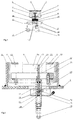
- Fig. 1 shows schematically a spring system according to an embodiment of the Invention
- Fig. 2 shows a schematic longitudinal section through part of a Embodiment of a spring system according to the invention.
- the body of the Rail vehicle indicated.
- the chassis frame of a not shown for springy undercarriage bears the reference number 2. It is about the body 1 cushion against the chassis frame 2, which is mainly about the air spring 3 happens, in the interior of which in normal operation via a filler opening 5 filled compressed air.
- Fig. 1 the measuring device around one connected to or pressed against the underside 8a of the piston 8 Measuring pin 12 carrying markings 14 readable by sensors 13.
- sensors 13 The exits
- inductive proximity sensors are equipped with an evaluation device 15 connected, which via the pressure pump 11 and the pressure of the hydraulic fluid Adjust the height of the emergency support 6 to a predetermined level.
- only two sensors 13 are shown, with which a regulation on a certain altitude of the emergency support 6 lying between the two sensors is possible.
- Fig. 2 shows a further embodiment, which is essentially the lower Part of Fig. 1 corresponds. You can still see the lower edge of the piston 8, the Bottom 8a serves as a measuring surface.
- the height of the piston 8 compared to that Housing 16 exactly reflects the height of the emergency support located above (in Fig. 2 not shown) again. It is therefore a matter of detecting the height of surface 8a.
- a measuring pin 12 is in the embodiment shown in FIG. 2 provided which is axially displaceably mounted in a sleeve-shaped guide 17, which can be connected to the housing 16.
- the measuring pin 12 has a thickened end 18 at the bottom, which has a piston with a Piston plate 18a forms.
- This piston crown 18a is from below with a Hydraulic fluid (hydraulic oil) applied via a line 19 and upwards pressed, with which the measuring pin 12 always abuts the surface 8a and thus whose vertical movement participates.
- a vent opening is provided with a filter 22 Mistake.
- the measuring pin 12 is hollow, it has a channel 20 and inside an outlet opening 21 for hydraulic oil. It is possible to use the Hydraulic oil supply 19 through the measuring pin 12 or its channel 20 through the Outflow opening 21 hydraulic fluid into the space 10 under the piston 8 bring.
- Two sensors 14 are provided for detecting the height of the measuring pin 12, which detect the height of the diameter variation 23 at the point where the Measuring pin 12 from its smaller upper diameter to the thicker lower one Diameter increases in the area of reference number 18. This diameter variation or edge is easily detectable, for example, by inductive proximity switches. Due to the electrical signals from these sensors 14, not shown Evaluation or control devices the hydraulic supply in the room 10 and thus the Adjust the height of the emergency support.
- the measuring direction can be arranged within the spring system and record the position of the emergency support more or less directly, for example by means of optical sensors.
- other sensors can also be used, for example, ultrasonic sensors or the like.
- Robust for railway operations Suitable sensors are certainly the inductive proximity switches mentioned above.
- the invention is also not based on the height adjustment via a hydraulic fluid limited, also differently adjustable emergency cushions are conceivable and possible.
Abstract
Description
Claims (8)
- Federsystem für ein Schienenfahrzeug, mit mindestens einer Federeinrichtung, insbesondere einer Luftfeder, und mit einer gegenüber dem Fahrwerksrahmen höhenverstellbar gelagerten Notauflage, auf die der Wagenkasten des Schienenfahrzeuges absinkt, wenn die Federeinrichtung ausfällt, gekennzeichnet durch eine gesonderte Meßeinrichtung (12, 13) zum Erfassen der Höhenlage der Notauflage (6) gegenüber dem Fahrwerksrahmen (2).
- Federsystem nach Anspruch 1, dadurch gekennzeichnet, daß die Meßeinrichtung (12, 13) einen an der Notauflage (6) bzw. einen damit verbundenen Teil (8) anliegenden bzw. damit in Verbindung stehenden, mechanischen Meßfühler (12) aufweist, dessen Lage an einer von der Notauflage (6) entfernten Stelle (8a) mit mindestens einem Sensor (13) erfaßt wird.
- Federsystem nach Anspruch 2, dadurch gekennzeichnet, daß der Meßfühler (12) einer axial verschiebbar gelagerter Meßstift ist.
- Federsystem nach Anspruch 3, dadurch gekennzeichnet, daß der Sensor (13) bzw. die Sensoren in bzw. an der vorzugsweise hülsenförmigen Führung (17) des Meßstiftes (12) angeordnet ist (sind).
- Federsystem nach einem der Ansprüche 2 bis 4, dadurch gekennzeichnet, daß der mindestens eine Sensor (13) ein induktiver Näherungsschalter ist, der eine Markierung (14) oder Durchmesservariation (23) des Meßfühlers (12) erfaßt.
- Federsystem nach einem der Ansprüche 1 bis 5, dadurch gekennzeichnet, daß die Notauflage (6) an einem Hydraulikstempel (7) ausgebildet ist, der von unten (10) mit unter Druck stehender Hydraulikflüssigkeit beaufschlagt ist und der von oben vorzugsweise unter der Wirkung einer Feder (9) steht.
- Federsystem nach einem der Ansprüche 1 bis 5 und Anspruch 6, dadurch gekennzeichnet, daß die vorzugsweise einen Meßstift umfassende Meßeinrichtung (12, 14) in den mit Hydraulikflüssigkeit gefüllten Raum (10) reicht und die Lage des unteren Kolbenbodens (8a) des Hydraulikstempels (17) erfaßt.
- Federsystem nach Anspruch 6 oder 7, dadurch gekennzeichnet, daß der Meßfühler (12) hohl ausgebildet ist und durch seinen Kanal (20) Zufuhr von Hydrauliköl in den Raum (10) unter dem Kolben (8) des Hydraulikstempels (17) erfolgt.
Priority Applications (1)
| Application Number | Priority Date | Filing Date | Title |
|---|---|---|---|
| AT99122820T ATE295291T1 (de) | 1998-12-03 | 1999-11-17 | Federsystem für schienenfahrzeug |
Applications Claiming Priority (2)
| Application Number | Priority Date | Filing Date | Title |
|---|---|---|---|
| AT204498 | 1998-12-03 | ||
| AT0204498A AT407031B (de) | 1998-12-03 | 1998-12-03 | Federund für ein schienenfahrzeug |
Publications (3)
| Publication Number | Publication Date |
|---|---|
| EP1006036A2 true EP1006036A2 (de) | 2000-06-07 |
| EP1006036A3 EP1006036A3 (de) | 2001-03-28 |
| EP1006036B1 EP1006036B1 (de) | 2005-05-11 |
Family
ID=3526572
Family Applications (1)
| Application Number | Title | Priority Date | Filing Date |
|---|---|---|---|
| EP99122820A Expired - Lifetime EP1006036B1 (de) | 1998-12-03 | 1999-11-17 | Federsystem für Schienenfahrzeug |
Country Status (3)
| Country | Link |
|---|---|
| EP (1) | EP1006036B1 (de) |
| AT (2) | AT407031B (de) |
| DE (1) | DE59912037D1 (de) |
Cited By (6)
| Publication number | Priority date | Publication date | Assignee | Title |
|---|---|---|---|---|
| DE10052806A1 (de) * | 2000-10-25 | 2002-05-08 | Alstom Lhb Gmbh | Abstützung von Schienenfahrzeugen mittels Luftfedersysteme |
| EP1308323A2 (de) * | 2001-11-06 | 2003-05-07 | ArvinMeritor Technology, LLC | Radaufhängung für ein Fahrzeug und Luftfederanordnung |
| EP1391331A2 (de) * | 2002-08-20 | 2004-02-25 | Liebherr-Aerospace Lindenberg GmbH | Hydropneumatisches Federelement mit integriertem Höhensensor oder Höhenregulierventil, für ein Schienenfahrzeug |
| NL1029266C2 (nl) * | 2005-06-16 | 2006-12-19 | Wp Suspension B V | Veerinrichting en werkwijze voor het aanpassen van de veerkarakteristiek van een veerinrichting. |
| EP2353962A1 (de) * | 2010-02-01 | 2011-08-10 | Stadler Bussnang AG | Fahrwerksanordnung für ein Schienenfahrzeug |
| EP2703245A3 (de) * | 2012-08-30 | 2014-04-23 | ContiTech Luftfedersysteme GmbH | Luftfedersystem für ein Schienenfahrzeug |
Families Citing this family (1)
| Publication number | Priority date | Publication date | Assignee | Title |
|---|---|---|---|---|
| CN112049876A (zh) * | 2019-06-06 | 2020-12-08 | 河北艾斯特瑞亚科技有限责任公司 | 一种推动膜活塞的气囊 |
Citations (1)
| Publication number | Priority date | Publication date | Assignee | Title |
|---|---|---|---|---|
| AT2471U1 (de) | 1997-07-23 | 1998-11-25 | Jenbacher Energiesysteme Ag | Federvorrichtung |
Family Cites Families (8)
| Publication number | Priority date | Publication date | Assignee | Title |
|---|---|---|---|---|
| GB893261A (en) * | 1958-02-28 | 1962-04-04 | Eaton Axles Ltd | Improvements in or relating to vehicle axle suspensions |
| GB1210465A (en) * | 1968-04-03 | 1970-10-28 | Gerald William Matthias Lush | Simplified vehicle suspension |
| SU1136999A1 (ru) * | 1982-12-07 | 1985-01-30 | Харьковский Ордена Ленина Политехнический Институт Им.В.И.Ленина | Устройство дл поддержани посто нного уровн между подрессоренной и неподрессоренной част ми локомотива при пневмоподвешивании |
| DE3711907A1 (de) * | 1987-04-08 | 1988-11-10 | Gutehoffnungshuette Man | Gleisbogenabhaengige wagenkastenneigungssteuerung fuer luftfeder-drehgestelle |
| JPH04175531A (ja) * | 1990-11-05 | 1992-06-23 | Aisin Seiki Co Ltd | エアサスペンションの変位センサ |
| DE4234523A1 (de) * | 1992-10-13 | 1994-04-14 | Knorr Bremse Ag | Niveau- und Neigungssteuerung eines Wagenkastens |
| WO1996011120A1 (en) * | 1994-10-07 | 1996-04-18 | Nai Neway, Inc. | Air spring with internal support member |
| DE29813031U1 (de) * | 1997-07-23 | 1998-11-12 | Integral Verkehrstechnik Ag | Federvorrichtung |
-
1998
- 1998-12-03 AT AT0204498A patent/AT407031B/de not_active IP Right Cessation
-
1999
- 1999-11-17 EP EP99122820A patent/EP1006036B1/de not_active Expired - Lifetime
- 1999-11-17 AT AT99122820T patent/ATE295291T1/de not_active IP Right Cessation
- 1999-11-17 DE DE59912037T patent/DE59912037D1/de not_active Expired - Lifetime
Patent Citations (1)
| Publication number | Priority date | Publication date | Assignee | Title |
|---|---|---|---|---|
| AT2471U1 (de) | 1997-07-23 | 1998-11-25 | Jenbacher Energiesysteme Ag | Federvorrichtung |
Cited By (11)
| Publication number | Priority date | Publication date | Assignee | Title |
|---|---|---|---|---|
| DE10052806A1 (de) * | 2000-10-25 | 2002-05-08 | Alstom Lhb Gmbh | Abstützung von Schienenfahrzeugen mittels Luftfedersysteme |
| EP1308323A2 (de) * | 2001-11-06 | 2003-05-07 | ArvinMeritor Technology, LLC | Radaufhängung für ein Fahrzeug und Luftfederanordnung |
| EP1308323A3 (de) * | 2001-11-06 | 2005-05-11 | ArvinMeritor Technology, LLC | Radaufhängung für ein Fahrzeug und Luftfederanordnung |
| EP1391331A2 (de) * | 2002-08-20 | 2004-02-25 | Liebherr-Aerospace Lindenberg GmbH | Hydropneumatisches Federelement mit integriertem Höhensensor oder Höhenregulierventil, für ein Schienenfahrzeug |
| EP1391331A3 (de) * | 2002-08-20 | 2004-07-14 | Liebherr-Aerospace Lindenberg GmbH | Hydropneumatisches Federelement mit integriertem Höhensensor oder Höhenregulierventil, für ein Schienenfahrzeug |
| US7520494B2 (en) | 2002-08-20 | 2009-04-21 | Liebherr-Aerospace Lindenberg Gmbh | Spring element |
| DE10238059B4 (de) * | 2002-08-20 | 2014-02-13 | Liebherr-Aerospace Lindenberg Gmbh | Federelement |
| NL1029266C2 (nl) * | 2005-06-16 | 2006-12-19 | Wp Suspension B V | Veerinrichting en werkwijze voor het aanpassen van de veerkarakteristiek van een veerinrichting. |
| EP1734277A1 (de) * | 2005-06-16 | 2006-12-20 | WP Suspension B.V. | Federvorrichtung für ein Kraftfahrzeug einschliesslich Druckfeder mit variabler Federcharakteristik |
| EP2353962A1 (de) * | 2010-02-01 | 2011-08-10 | Stadler Bussnang AG | Fahrwerksanordnung für ein Schienenfahrzeug |
| EP2703245A3 (de) * | 2012-08-30 | 2014-04-23 | ContiTech Luftfedersysteme GmbH | Luftfedersystem für ein Schienenfahrzeug |
Also Published As
| Publication number | Publication date |
|---|---|
| DE59912037D1 (de) | 2005-06-16 |
| ATA204498A (de) | 2000-04-15 |
| AT407031B (de) | 2000-11-27 |
| ATE295291T1 (de) | 2005-05-15 |
| EP1006036B1 (de) | 2005-05-11 |
| EP1006036A3 (de) | 2001-03-28 |
Similar Documents
| Publication | Publication Date | Title |
|---|---|---|
| AT500202B1 (de) | Vorrichtung zur sekundärfederung eines wagenkastens bei einem schienenfahrzeug mit einem aktiven federelement | |
| EP1391331B1 (de) | Hydropneumatisches Federelement mit integriertem Höhensensor oder Höhenregulierventil, für ein Schienenfahrzeug | |
| AT407031B (de) | Federund für ein schienenfahrzeug | |
| AT500278B1 (de) | Vorrichtung zur sekundärfederung eines wagenkastens bei einem schienenfahrzeug mit einem passiven federelement | |
| DE202016004888U1 (de) | Fußpodest mit höhenverstellbarer Trittplatte zum Führen eines Fahrzeuges, vorzugsweise eines Schienenfahrzeuges | |
| DE2440094B2 (de) | Aufzugspuffer | |
| DE1978953U (de) | Kraftfahrzeugsitz. | |
| DE944846C (de) | Einrichtung zum Konstanthalten des Abstandes von mit einer hydraulisch-elektrisch gesteuerten Anstellvorrichtung versehenen Walzwerkwalzen | |
| DE3000237C2 (de) | ||
| DE1103954B (de) | Fahrbare Gleisstopfmaschine | |
| DE1958048A1 (de) | Bremsanordnung fuer Rangierzwecke | |
| DE2055220B2 (de) | Schienenfahrzeug mit regulierbaren druckmittelfedern | |
| AT500201A2 (de) | Vorrichtung zur sekundärfederung eines wagenkastens bei einem schienenfahrzeug mit einem aktiven federelement | |
| DE2313887B2 (de) | Reibungsarme, gefederte und wiegenlose fuehrung und abstuetzung zwischen dem wagenkasten und den drehgestellen von schienenfahrzeugen | |
| DE1482917B2 (de) | Regelvorrichtung zur aufrechterhaltung eines konstanten druckes eines stroemungsmittels in einem stellzylinder einer landmaschine | |
| DE2649868A1 (de) | Zeichentisch fuer hoehenverstellbare zeichenbretter | |
| EP0356835A2 (de) | Stromabnehmer für elektrisch angetriebene Fahrzeuge mit Einrichtung zur Schnellabsenkung | |
| DE939213C (de) | Gleisbremse mit paarig angeordneten Bremstraegern | |
| DE1534089C3 (de) | Am Fahrgestellrahmen einer Gleisstopf- und -nivelliermaschine angeordnete Hubvorrichtung | |
| AT141212B (de) | Schienen-Druckkontaktvorrichtung. | |
| DE19881900B4 (de) | Gleisbremseinrichtung | |
| DE1605836C (de) | Einrichtung zum Steuern der Neigung eines Fahrzeugs, insbesondere eines Eisenbahnwagens | |
| DE412045C (de) | Anlaufbahn an Sicherheitsvorrichtungen fuer die Haupt- und Vorsignale bei Eisenbahnen | |
| DE657557C (de) | Vorrichtung zum Ausgleich des Bremskolbenhubes bei Fahrzeugbremsen mit umstellbarer Bremskraft | |
| AT401374B (de) | Steuervorrichtung für stromabnehmer |
Legal Events
| Date | Code | Title | Description |
|---|---|---|---|
| PUAI | Public reference made under article 153(3) epc to a published international application that has entered the european phase |
Free format text: ORIGINAL CODE: 0009012 |
|
| AK | Designated contracting states |
Kind code of ref document: A2 Designated state(s): AT CH DE FR IT LI |
|
| AX | Request for extension of the european patent |
Free format text: AL;LT;LV;MK;RO;SI |
|
| PUAL | Search report despatched |
Free format text: ORIGINAL CODE: 0009013 |
|
| AK | Designated contracting states |
Kind code of ref document: A3 Designated state(s): AT BE CH CY DE DK ES FI FR GB GR IE IT LI LU MC NL PT SE |
|
| AX | Request for extension of the european patent |
Free format text: AL;LT;LV;MK;RO;SI |
|
| 17P | Request for examination filed |
Effective date: 20010705 |
|
| AKX | Designation fees paid |
Free format text: AT CH DE FR IT LI |
|
| RAP1 | Party data changed (applicant data changed or rights of an application transferred) |
Owner name: CONNEX VERKEHR GMBH |
|
| 17Q | First examination report despatched |
Effective date: 20030718 |
|
| GRAP | Despatch of communication of intention to grant a patent |
Free format text: ORIGINAL CODE: EPIDOSNIGR1 |
|
| GRAS | Grant fee paid |
Free format text: ORIGINAL CODE: EPIDOSNIGR3 |
|
| GRAA | (expected) grant |
Free format text: ORIGINAL CODE: 0009210 |
|
| AK | Designated contracting states |
Kind code of ref document: B1 Designated state(s): AT CH DE FR IT LI |
|
| REG | Reference to a national code |
Ref country code: CH Ref legal event code: EP |
|
| REF | Corresponds to: |
Ref document number: 59912037 Country of ref document: DE Date of ref document: 20050616 Kind code of ref document: P |
|
| REG | Reference to a national code |
Ref country code: CH Ref legal event code: NV Representative=s name: ISLER & PEDRAZZINI AG |
|
| PG25 | Lapsed in a contracting state [announced via postgrant information from national office to epo] |
Ref country code: AT Free format text: LAPSE BECAUSE OF NON-PAYMENT OF DUE FEES Effective date: 20051117 |
|
| PLBE | No opposition filed within time limit |
Free format text: ORIGINAL CODE: 0009261 |
|
| STAA | Information on the status of an ep patent application or granted ep patent |
Free format text: STATUS: NO OPPOSITION FILED WITHIN TIME LIMIT |
|
| ET | Fr: translation filed | ||
| 26N | No opposition filed |
Effective date: 20060214 |
|
| REG | Reference to a national code |
Ref country code: CH Ref legal event code: PCAR Free format text: ISLER & PEDRAZZINI AG;POSTFACH 1772;8027 ZUERICH (CH) |
|
| PG25 | Lapsed in a contracting state [announced via postgrant information from national office to epo] |
Ref country code: IT Free format text: LAPSE BECAUSE OF NON-PAYMENT OF DUE FEES Effective date: 20071117 |
|
| PGFP | Annual fee paid to national office [announced via postgrant information from national office to epo] |
Ref country code: CH Payment date: 20091117 Year of fee payment: 11 |
|
| PGFP | Annual fee paid to national office [announced via postgrant information from national office to epo] |
Ref country code: FR Payment date: 20091201 Year of fee payment: 11 |
|
| PGFP | Annual fee paid to national office [announced via postgrant information from national office to epo] |
Ref country code: DE Payment date: 20100122 Year of fee payment: 11 |
|
| REG | Reference to a national code |
Ref country code: CH Ref legal event code: PL |
|
| PG25 | Lapsed in a contracting state [announced via postgrant information from national office to epo] |
Ref country code: CH Free format text: LAPSE BECAUSE OF NON-PAYMENT OF DUE FEES Effective date: 20101130 Ref country code: LI Free format text: LAPSE BECAUSE OF NON-PAYMENT OF DUE FEES Effective date: 20101130 |
|
| PGFP | Annual fee paid to national office [announced via postgrant information from national office to epo] |
Ref country code: IT Payment date: 20091124 Year of fee payment: 11 |
|
| PGRI | Patent reinstated in contracting state [announced from national office to epo] |
Ref country code: IT Effective date: 20110616 |
|
| REG | Reference to a national code |
Ref country code: FR Ref legal event code: ST Effective date: 20110801 |
|
| REG | Reference to a national code |
Ref country code: DE Ref legal event code: R119 Ref document number: 59912037 Country of ref document: DE Effective date: 20110601 Ref country code: DE Ref legal event code: R119 Ref document number: 59912037 Country of ref document: DE Effective date: 20110531 |
|
| PG25 | Lapsed in a contracting state [announced via postgrant information from national office to epo] |
Ref country code: DE Free format text: LAPSE BECAUSE OF NON-PAYMENT OF DUE FEES Effective date: 20110531 |
|
| PG25 | Lapsed in a contracting state [announced via postgrant information from national office to epo] |
Ref country code: FR Free format text: LAPSE BECAUSE OF NON-PAYMENT OF DUE FEES Effective date: 20101130 |
|
| PGRI | Patent reinstated in contracting state [announced from national office to epo] |
Ref country code: IT Effective date: 20110616 |