EP1004439A1 - Verfahren und Vorrichtung zum Positionieren und Spannen eines Zylinderaufzuges auf einem Druckmaschinenzylinder - Google Patents
Verfahren und Vorrichtung zum Positionieren und Spannen eines Zylinderaufzuges auf einem Druckmaschinenzylinder Download PDFInfo
- Publication number
- EP1004439A1 EP1004439A1 EP99120994A EP99120994A EP1004439A1 EP 1004439 A1 EP1004439 A1 EP 1004439A1 EP 99120994 A EP99120994 A EP 99120994A EP 99120994 A EP99120994 A EP 99120994A EP 1004439 A1 EP1004439 A1 EP 1004439A1
- Authority
- EP
- European Patent Office
- Prior art keywords
- elevator
- cylinder
- tensioning
- clamping
- spring
- Prior art date
- Legal status (The legal status is an assumption and is not a legal conclusion. Google has not performed a legal analysis and makes no representation as to the accuracy of the status listed.)
- Granted
Links
Images


Classifications
-
- B—PERFORMING OPERATIONS; TRANSPORTING
- B41—PRINTING; LINING MACHINES; TYPEWRITERS; STAMPS
- B41F—PRINTING MACHINES OR PRESSES
- B41F30/00—Devices for attaching coverings or make-ready devices; Guiding devices for coverings
- B41F30/04—Devices for attaching coverings or make-ready devices; Guiding devices for coverings attaching to transfer cylinders
-
- B—PERFORMING OPERATIONS; TRANSPORTING
- B41—PRINTING; LINING MACHINES; TYPEWRITERS; STAMPS
- B41F—PRINTING MACHINES OR PRESSES
- B41F27/00—Devices for attaching printing elements or formes to supports
- B41F27/12—Devices for attaching printing elements or formes to supports for attaching flexible printing formes
- B41F27/1218—Devices for attaching printing elements or formes to supports for attaching flexible printing formes comprising printing plate tensioning devices
- B41F27/1225—Devices for attaching printing elements or formes to supports for attaching flexible printing formes comprising printing plate tensioning devices moving in the printing plate end substantially rectilinearly
- B41F27/1243—Devices for attaching printing elements or formes to supports for attaching flexible printing formes comprising printing plate tensioning devices moving in the printing plate end substantially rectilinearly by pivotal or swivelling motion, e.g. by means of a rocking lever
-
- B—PERFORMING OPERATIONS; TRANSPORTING
- B41—PRINTING; LINING MACHINES; TYPEWRITERS; STAMPS
- B41P—INDEXING SCHEME RELATING TO PRINTING, LINING MACHINES, TYPEWRITERS, AND TO STAMPS
- B41P2227/00—Mounting or handling printing plates; Forming printing surfaces in situ
- B41P2227/40—Adjusting means for printing plates on the cylinder
- B41P2227/42—Adjusting means for printing plates on the cylinder circumferentially
Definitions
- the invention relates to a method for positioning and clamping a cylinder elevator on a printing press cylinder, both a front end of the elevator and a rear end of the elevator can be stretched, according to the preamble of claim 1.
- the invention further relates to a device for holding and tensioning a cylinder lift on a Printing press cylinder, with a first holding a first end of the elevator Arm, a second arm holding a second end of the elevator and one for Adjustment of both arms rotatable cam part, according to the generic term of Claim 4.
- Such a method can be used, for example, with that in DE 42 22 332 C2 perform the described device, with a clamping due to the design and relaxing the cylinder lift at its front and Trailing edge.
- the cylinder lift can be on the jacket of the Press cylinder shifted relative to its original position become.
- the rubber blanket is actuated by an actuator on its front and Relaxed rear edge, a toothed segment clamp on a clamping spindle solved and rotated this by a travel.
- the object is achieved by a method using Features of claim 1 solved.
- the procedure for positioning and tensioning a cylinder lift a printing press cylinder, with both a front elevator end and a rear end of the elevator can also be tensioned, that both elevator ends are tensioned in a first process step and in a second step following the first step Method step relaxed a first elevator end of the two elevator ends and a second elevator end of the two elevator ends is re-tensioned.
- the cylinder lift is in this simple manner in the circumferential direction the circumferential surface of the cylinder slidably, in the clamping direction the second end of the elevator practically pushed the first end of the elevator and the second end of the elevator is pulled.
- voltage of the first elevator end is in the second Process step often only requires partial relaxation.
- the first end of the elevator can either be relaxed before re-tensioning start of the second end of the elevator or simultaneously with the latter. In both The second lift ends during the relaxation of the first Retensioned end of elevator.
- the method according to the invention is based on the assumption that also such exciting cylinder lifts on the peripheral surface of the Have cylinders moved if moving both ends Tension precedes. It is believed that disturbing during the clamping Deformations of the cylinder lift in addition to the side friction-like effect Role-play. Especially after prolonged use and related repeated clamping and removal of the cylinder lift on the or permanent deformations are often noticeable from the cylinder. By the two-sided tight spans preceding the shift such deformations are eliminated so that the cylinder lift afterwards, lighter than previously thought, on the circumferential surface of the cylinder move and position exactly.
- a front elevator end preferably corresponds to the first elevator end and the second end of the elevator a rear end of the elevator, so that in the second Method step at least partially relaxed the front end of the elevator and the rear end of the elevator is tightened.
- Under the front The end of the elevator is understood to mean that which occurs when the Printing machine cylinder carrying cylinder lift in operative contact with another printing press cylinder first on every revolution another printing press cylinder is passed.
- the Press cylinder A plate cylinder for applying an ink or a varnish on one substrate and the other Printing press cylinder an impression cylinder guiding the substrate is the so-called start of printing of the printing or lacquer plate on the front End of elevator.
- a further developing the method according to the invention Process design means that in the first process step Lift ends are stretched one after the other. Preferably in the first Process step first the rear end of the elevator and then the front end The end of the elevator.
- a further process design includes that in the first Process step both elevator ends are tensioned simultaneously.
- a device designed as described at the beginning is, for example, in DE-OS 23 28 985 shown in Figures 1 to 3.
- the arms are not designed to be pivotable about a swivel joint Clamping lever formed, but around a bending point of a U-shaped Spring movable.
- the arms are not loaded by a spring either, but even resilient and parts of the U-shaped spring.
- a disadvantage of this device is that the printing plates by means of this Do not allow the device to be positioned precisely, because depending on Stretchability of the clamped plate type the arms once more and bend less another time. In connection with this is also the comparatively low tension effect, which is due to the u-shaped spring can be achieved.
- the device according to the invention is by means of this device Procedure not feasible, because of design reasons only one One end of the elevator is stretched while the other end of the elevator is held stationary on the printing plate cylinder.
- the object is achieved by a device with the Features of claim 4 solved.
- the device for holding and tensioning a cylinder lift on a Printing press cylinder with one holding a front end of the elevator first arm and a second arm holding a rear end of the elevator and with a rotating cam part that understands both arms, especially for Implementation of the method according to the invention is characterized in that that the first arm on a first pivotable about a first pivot Tension lever and the second arm on one around a second swivel joint pivotable second clamping lever is formed.
- the device according to the invention has the advantage that with the device according to the invention cylinder lifts Align positionally.
- the arms may be stiff so that the cylinder lift held on the arms regardless of its elasticity by an appropriate adjustment of the Arms can be positioned.
- An embodiment further developing the device according to the invention is characterized in that the tensioning lever by at least a total a spring is loaded.
- Each clamping lever can have at least one clamping force on the Tension lever-transmitting spring must be assigned. Any of these feathers can itself on the cylinder body, in which the clamping lever over the swivel joints can be supported. Preferably at least one can also be the spring tensioning two tensioning levers may be provided. In this case, the tension levers can be used together with the one between them acting spring one without changing the tension to tension the Cylinder lift relative to the cylinder body essentially in Form a circumferentially adjustable clamping unit. By means of a spring or the multiple springs can generate much higher clamping forces than this is possible with resilient arms. Because of the stiffness of the arms increases the stability of the entire clamping device and a distortion-free The cylinder lift can be tensioned very well
- Another embodiment is characterized in that the first The swivel joint and the second swivel joint are arranged coaxially to one another.
- one of the rotary joints can sit concentrically on the other swivel.
- the second variant are the swivel joints in their axial direction to each other staggered.
- the second variant at the two ends of a pivot pin one rotatable on it Articulated bushing, which is attached to the respective clamping lever.
- the pivot pin be wound helically, the Leg spring with each of its two legs on one of the tension levers supports and braced them against each other.
- the common central axis of the Swivel joints can be used both in the first variant and in the second Correspond to the variant of the axis of rotation of the printing press cylinder.
- Another embodiment is characterized in that the swivel joints eccentrically offset to an axis of rotation of the printing press cylinder are arranged.
- the advantage of this embodiment is that it is inexpensive Space distribution is achieved inside the cylinder.
- the axis of rotation of the Can eccentrically offset swivel joints of the clamping levers to be arranged offset to one another, the joint axes being axially parallel to each other and parallel to the axis of rotation of the cylinder.
- the rotary joints are preferably arranged coaxially to one another, the common axis of rotation offset eccentrically and parallel to the axis of rotation of the cylinder is arranged.
- Another embodiment is characterized in that the first Swivel and by the second swivel a single or a spring is passed through.
- the pivot pins of the swivel joints can be one each tubular hollow body may be formed, on which the clamping lever, for. B. carried by joint bushings, sit.
- the spring can be inserted into the hollow bodies non-rotatable positive connection to the hollow bodies.
- a joint pivot can both Swivel joints on which the clamping levers are rotatably seated as a single one tubular hollow body through which the spring is passed through.
- Another embodiment is characterized in that the spring is a or is a torsion bar spring in each case.
- torsion bar By means of a torsion bar, large clamping forces of e.g. B. 8 kN for Stretching a lacquer cloth or 12 kN for stretching a lacquer plate apply, the torsion bar spring only comparatively little space claimed. In certain applications, one can or can several z. B. designed as a coil spring compression for tensioning the clamping lever must be used against each other.
- Another embodiment is characterized in that the clamping lever are designed as rockers and each of the rockers the cylinder lift holding first rocker arm and a second operated by the cam part Has rocker arm.
- the second rocker arms can be operated by actuating the cam part this occasionally come in and out of contact.
- the second rocker arms in a predominantly permanent system on the rotating Cam part held so that the position of the clamping lever is securely fixed.
- Another embodiment is characterized in that in the second Rocker arms each have a roller that can be contacted by the cam part is rotatably mounted.
- the rollers can roll on the cam part, making it easy to use Ease of movement of the adjustment device is given and any Abrasion wear of the cam part or the tensioning lever is avoided.
- Another embodiment is characterized in that the clamping lever Wear a clamp to hold the cylinder lift. This can on the first rocker arm of the first clamping lever, a clamping device for Pinch the front end of the elevator and the first rocker arm of the second clamping lever another clamping device for clamping the be arranged rear elevator end.
- the clamps can be very quickly manufacture and loosen, so that a replacement of the cylinder lift takes up little time against another cylinder lift.
- the device is in rotary printing machines and z. B. offset printing machines usable.
- the press cylinder can be a Coating cylinder for coating the substrate of the Printing units upstream or downstream of the printing press Coating unit, which is equipped with the device.
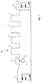
- Fig. 1 is designed as an offset rotary printing press Printing machine 49 with a plurality of printing units 1 arranged in a row to 4, a sheet feeder 6 and a sheet delivery 7 shown.
- the Printing machine 49 has a coating unit 5 which between the last printing unit 4 and the sheet delivery 7 is arranged and also be arranged between the sheet feeder 6 and the first printing unit 1 can.
- the coating unit 5 comprises two interacting Printing press cylinders 8, 9, namely the coating cylinder 8 for Applying a coating liquid, e.g. B. a paint, on a Substrate sheet, and the impression cylinder 9, on which the Substrate sheet lies on during coating.
- a coating liquid e.g. B. a paint
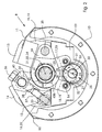
- the coating cylinder 8 is in cross section with a view of an Device arranged inside the cylinder for clamping different Cylinder lifts 10, which a rubber blanket or a polyester plate for Paint application or, as shown, a paint plate on an aluminum support base can, shown.
- Cylinder lifts 10 require different clamping paths and tensile forces, which of the designed as a torsion bar 41 and torsion claimable spring 41 are applied and by means of a Adjustment device 33, 34, 36 to 38 can be varied by the bias of the Spring 41 is adjustable to adapt to the materials.
- adjustable clamping device can also be very well used and therefore preformed cylinder lifts 10 span, which is usually one compared to unused Cylinder lifts 10 require slightly higher clamping force.
- the Coating cylinder 8 meshes with the grippers 52 of the impression cylinder 9 (Fig.
- the device according to the invention enables both ends spring-assisted tensioning of the cylinder lift 10 in addition Positioning on the coating cylinder 8, the one on the front The end of the elevator 12, the so-called start of pressure via a curve control 25 to 32 reproducible when clamping the cylinder lift 10 can be aligned by adjusting both the front Elevator end 12 and the rear elevator end 11 of the Cylinder lift 10 is displaceable on the coating cylinder 8.
- the front elevator end 12 is in a front Holding device 14 and the rear elevator end 11 in a rear Holding device 13 clamped and still untensioned.
- Clamping devices 13, 14 are formed by holding devices first rocker arms 15, 16 each carried, the first rocker arm 16 together with a second rocker arm 17 a first clamping lever 20 in Form a rocker 20 and the first rocker arm 15 together with one second rocker arm 18 a second clamping lever 19 in the form of a rocker 19th forms.
- the clamping levers 19, 20 deviating from their shown training also as a one-armed lever be trained.
- the tensioning levers 19, 20 are arranged coaxially around them Joints 21, 22 pivotable, with a common pivot axis 24 of the Joints 21, 22 eccentrically in the direction of a cylinder axis 23 between the elevator ends 11, 12 free clamping gap is offset and runs axially parallel to the cylinder axis 23.
- Cam part 25 offset which from a rotatable about the cam axis 26 Actuating shaft 53 and a cam 54 seated on the adjusting shaft 53 different circumferential curve areas 27 to 30.
- the Tension levers 19, 20 are each provided with a cam roller 31, 32, which simultaneously roll on the cam member 25 as it rotates. In particular Applications, the rollers 31, 32 can be omitted, so that Cam part 25, the clamping lever 19, 20 actuated in direct contact.
- the spring 41 braces the two clamping levers 19, 20 against each other on the one hand the first rocker arms 15, 16 and with these the holding devices 13, 14 and, on the other hand, the second rocker arms 17, 18 one on top of the other are pulled, whereby the cylinder lift 10 at the appropriate Rotational position of the cam member 25 is tensioned and the rollers 31, 32 on the Cam part 25 are pressed.
- the cam part 25 and especially its cam 54 has one for Cam axis 27 equidistant locking circle with a large radius R and one also equidistant locking circle with a small radius r, the two locking circles R, r over an S-shaped and one mirror-inverted S-shaped curved transition area flowing into each other pass over.
- the detent circle with the large radius R has one Flattening or concave indentation forming curve area 28 in the middle position of the cam part 25 shown in FIG. 2 in the second Quadrant lies.
- the curve area 28 is the cam mirror-symmetrical, the locking circle with the larger Radius R over a larger and approximately twice the circumferential angle how the rest circle extends with the smaller radius r. Clockwise seen the indentation 28 follow in turn the convex area 29, a first transition region, the convex region 30, a second Transitional area and the convex area 27.
- the cam part 25 is shown in a central position, in which the tension levers 19, 20 are spread apart to the maximum, this being the case with the shown, arranged cross-shaped, seesaw-shaped Tension levers 19, 20 both for the second rocker arms 17, 18 and for the first rocker arms 15, 16 applies, so that the latter the cylinder elevator 10th keep tension at both ends.
- the tension levers 19, 20 are spread apart to the maximum, this being the case with the shown, arranged cross-shaped, seesaw-shaped Tension levers 19, 20 both for the second rocker arms 17, 18 and for the first rocker arms 15, 16 applies, so that the latter the cylinder elevator 10th keep tension at both ends.
- In the area of the first quadrant are in this middle position of the first clamping lever 20 on the roller 31 on arcuate curve area 29 and in the area of the second quadrant the second clamping lever 19 on the roller 32 on a circular arc Curve area 27 on.
- the setting device 33 to 38 for setting different sizes and preload tension and tension forces of the torsion bar spring 41 consists of a screw 36 which has different types of thread 37, 38, namely with a right-hand thread 37 and a left-hand thread 38, is provided so that with a screw revolution compared to a conventional screw with the same thread pitch double the travel is realizable, the adjusting device 33 to 38 comparatively little Takes up space.
- the screw 36 rotates about its Longitudinal axis are the first clamping lever 20 and a non-rotatable form fit 45 a on a first tube 42 seated first support arm 40 depending Direction of rotation of the screw 36 either towards or from each other adjustable way.
- the screw 36 is with its right-hand thread 37 in a rotatably mounted in the first clamping lever 20 to the cylinder 8 axially parallel first connecting bolt 33 and with their left-hand thread 38 in one as well articulated bolt 33 mounted in the first support arm 40. At a Tightening or loosening the screw 36 rotates the bolts 33, 34 within the tensioning lever 20 or the first support arm 40.
- the right and left-hand threads can be interchanged Arrangement and can with enough space around a single thread be provided.
- FIG. 7 For a better understanding of the further description, FIG. 7 be involved.
- the second clamping lever 19 is connected to a second connecting pin 35 a second support arm 39 articulated.
- the second support arm 39 is seated in the non-rotatable form fit 45 b on a second tube 43.
- a rotatably mounted tubes 42, 43 By both in Cylinder base body 51 by means of the pivot bearing 47 a rotatably mounted tubes 42, 43, the spring 41 is passed through and each tube 42, 43 is non-rotatable Positive locking 44, 46 connected to the spring 41.
- the tubes 42, 43 can for example, inside polygonal, z. B. profiled as shown hexagonal and this hexagon profile on a corresponding outside counterpart the spring 41 can be plugged tight.
- a comparable rotatable Plug connection of the support arms 39, 40 with the tubes 42, 43 can by shown inside hexagonal profiling of the former and outside Hexagonal profiling can be achieved.
- the entire clamping system consisting of the each other through the Spring 41 clamped tension levers 19, 20, tubes 42, 43, support arms 39, 40 and the spring 41 itself is mounted as a so-called floating System, that is, as an overall adjustable structural unit via which Rotary bearing 47 a rotatably mounted in the cylinder body 41.
- This has the Advantage that the clamping system for example Circumferential register adjustment causing displacement of the cylinder lift 10 by means of a rotation of the cam part 25 close to the Cylinder axis 23 lying joint axis 24 can be adjusted. That in Fig. 2 shown cam part 25 is for reasons of better clarity in the Fig. 7 not shown again.
- the curve contour 26 to 30 of the cam part 25 causes when it rotates in a direction of rotation, e.g. B. as shown in Figures 2 to 5 in Clockwise rotation, a certain sequence of lever operation when clamping and thereby shifting the cylinder circumference positioning cylinder lift 10.
- both the front is supported First tension arm 20 holding end of elevator 12 of cylinder elevator 10 the roller 31 resting on the curve region 29 and also the rear roller Second tension arm 19 holding elevator end 11 via the one on curve area 27 adjacent roller 32 on the cam part 25.
- Both rollers 31, 32 are located thereby on the same locking circle with the radius R of the cams 54.
- both elevator ends 11, 12 are untensioned, like this can be seen from the bulges of the cylinder lift 10 close to the edge.
Abstract
Description
- Fig. 1
- eine Druckmaschine mit einem Beschichtungswerk, dessen Beschichtungszylinder mit der erfindungsgemäßen Vorrichtung ausgestattet ist,
- Fig. 2
- einen Querschnitt durch den Beschichtungszylinder, dessen Spannvorrichtung sich in einer ersten Spannstellung befindet, bei welcher sie einen Zylinderaufzug an beiden Aufzugsenden ungespannt hält,
- Fig. 3
- die Spannvorrichtung in derselben Ansicht, wobei sich diese in einer zweiten Spannstellung befindet, in welcher ein vorderes Aufzugsende ungespannt ist und ein hinteres Aufzugsende gespannt wird,
- Fig. 4
- die Spannvorrichtung in einer dritten Spannstellung, in welcher beide Aufzugsenden gespannt werden,
- Fig. 5
- die Spannvorrichtung in einer vierten Spannstellung, bei welcher das vordere Aufzugsende entspannt und das hintere Aufzugsende nachgespannt wird,
- Fig. 6
- die Spannvorrichtung in einer fünften Spannstellung, in welcher beide Aufzugsenden positioniergenau ausgerichtet sowie gespannt sind und
- Fig. 7
- eine schematische Darstellung der in den Figuren 2 bis 6 gezeigten Spannvorrichtung in einer Draufsicht.
- 1 bis 4
- Druckwerk
- 5
- Beschichtungswerk
- 6
- Bogenanleger
- 7
- Bogenausleger
- 8
- Beschichtungszylinder
- 9
- Gegendruckzylinder
- 10
- Zylinderaufzug
- 11, 12
- Aufzugsende
- 13, 14
- Klemmeinrichtung
- 15 bis 18
- Wippenarm
- 19, 20
- Wippe
- 21, 22
- Drehgelenk
- 23
- Zylinderachse
- 24
- Gelenkachse
- 25
- Nockenteil
- 26
- Nockenachse
- 27 bis 30
- Kurvenbereich
- 31, 32
- Rolle
- 33, 34, 35
- Bolzen
- 36
- Schraube
- 37, 38
- Gewinde
- 39, 40
- Stützarm
- 41
- Drehstabfeder
- 42, 43
- Rohr
- 44, 45 a, 45 b, 46
- Steckverbindung
- 47 a, 47 b
- Drehlager
- 48
- Querträger
- 49
- Rotationsdruckmachine
- 50
- Aufzugsverformung
- 51
- Zylindergrundkörper
- 52
- Greifer
- 53
- Stellwelle
- 54
- Kurvenscheibe
Claims (13)
- Verfahren zum Positionieren und Spannen eines Zylinderaufzuges (10) auf einem Druckmaschinenzylinder (8), wobei sowohl ein vorderes Aufzugsende (12) als auch ein hinteres Aufzugsende (11) des Zylinderaufzuges (10) gespannt werden,
gekennzeichnet durch
einen ersten Verfahrensschritt, bei welchem beide Aufzugsenden (11,12) gespannt werden und einem zweiten Verfahrensschritt, bei welchem ein erstes der beiden Aufzugsenden (11,12), insbesondere das vordere Aufzugsende (12), entspannt wird, während ein zweites Aufzugsende (11, 12), insbesondere das hintere Aufzugsende (11), nachgespannt wird. - Verfahren nach Anspruch 1,
gekennzeichnet durch
ein nacheinander erfolgendes Spannen der Aufzugsenden (11,12) und insbesondere ein zuerst erfolgendes Spannen des hinteren Aufzugsendes (11) und ein dem nachfolgendes Spannen des vorderen Aufzugsendes (12) im ersten Verfahrensschritt. - Verfahren nach Anspruch 1,
gekennzeichnet durch
ein gleichzeitiges Spannen der Aufzugsenden (11, 12) im ersten Verfahrensschritt. - Vorrichtung zum Halten und Spannen eines Zylinderaufzuges (10) auf einem Druckmaschinenzylinder (8), mit einem ein vorderes Aufzugsende (12) des Zylinderaufzuges (10) haltenden ersten Arm (16), einem ein hinteres Aufzugsende (11) des Zylinderaufzuges (10) haltenden zweiten Arm (15) und mit einem beide Arme (15, 16) verstehenden drehbaren Nockenteil (25), insbesondere zur Durchführung des Verfahrens nach einem der Ansprüche 1, 2 oder 3,
dadurch gekennzeichnet,
daß der erste Arm (16) an einem um ein erstes Drehgelenk (22) schwenkbaren ersten Spannhebel (20) und der zweite Arm (15) an einem um ein zweites Drehgelenk (21) schwenkbaren zweiten Spannhebel (19) ausgebildet ist. - Vorrichtung nach Anspruch 4,
dadurch gekennzeichnet,
daß die Spannhebel (19, 20) durch insgesamt zumindest eine Feder (41) belastet sind. - Vorrichtung nach Anspruch 4 oder 5,
dadurch gekennzeichnet,
daß das erste Drehgelenk (22) und das zweite Drehgelenk (21) koaxial zueinander angeordnet sind. - Vorrichtung nach einem der Ansprüche 4 bis 6,
dadurch gekennzeichnet,
daß die Drehgelenke (21, 22) exzentrisch versetzt zu einer Drehachse (23) des Druckmaschinenzylinders (8) angeordnet sind. - Vorrichtung nach einem der Ansprüche 4 bis 7,
dadurch gekennzeichnet,
daß durch das erste Drehgelenk (22) und durch das zweite Drehgelenk (21) eine oder je eine Feder (41) hindurchgeführt ist. - Vorrichtung nach Anspruch 8,
dadurch gekennzeichnet,
daß die einzige Feder (41) eine Drehstabfeder (41) oder jede Feder (41) jeweils eine Drehstabfeder (41) ist. - Vorrichtung nach einem der Ansprüche 4 bis 9,
dadurch gekennzeichnet,
daß die Spannhebel (19, 20) als Wippen (19, 20) ausgebildet sind und jede der Wippen (19, 20) einen den Zylinderaufzug (10) haltenden ersten Wippenarm (15, 16) und einen vom Nockenteil (25) betätigbaren zweiten Wippenarm (17,18) aufweist. - Vorrichtung nach Anspruch 10,
dadurch gekennzeichnet,
daß in den zweiten Wippenarmen (17, 18) je eine vom Nockenteil (25) kontaktierbare Rolle (31, 32) drehbar gelagert ist. - Vorrichtung nach einem der Ansprüche 4 bis 11,
dadurch gekennzeichnet,
daß die Spannhebel (19, 20) je eine Klemmeinrichtung (13, 14) zum Halten des Zylinderaufzuges (10) tragen. - Druckmaschine (49) mit mindestens einer nach einem der Ansprüche 4 bis 12 ausgebildeten Vorrichtung.
Applications Claiming Priority (2)
| Application Number | Priority Date | Filing Date | Title |
|---|---|---|---|
| DE19854526 | 1998-11-26 | ||
| DE19854526A DE19854526A1 (de) | 1998-11-26 | 1998-11-26 | Verfahren und Vorrichtung zum Spannen eines Zylinderaufzuges auf einem Druckmaschinenzylinder |
Publications (2)
| Publication Number | Publication Date |
|---|---|
| EP1004439A1 true EP1004439A1 (de) | 2000-05-31 |
| EP1004439B1 EP1004439B1 (de) | 2003-06-04 |
Family
ID=7889066
Family Applications (1)
| Application Number | Title | Priority Date | Filing Date |
|---|---|---|---|
| EP99120994A Expired - Lifetime EP1004439B1 (de) | 1998-11-26 | 1999-11-04 | Verfahren und Vorrichtung zum Positionieren und Spannen eines Zylinderaufzuges auf einem Druckmaschinenzylinder |
Country Status (5)
| Country | Link |
|---|---|
| US (1) | US6520085B1 (de) |
| EP (1) | EP1004439B1 (de) |
| JP (1) | JP4948693B2 (de) |
| AT (1) | ATE242122T1 (de) |
| DE (2) | DE19854526A1 (de) |
Cited By (1)
| Publication number | Priority date | Publication date | Assignee | Title |
|---|---|---|---|---|
| DE102004005577B4 (de) * | 2003-02-14 | 2007-10-04 | Heidelberger Druckmaschinen Ag | Vorrichtung zum Spannen eines Aufzugs auf einem Zylinder einer Bedruckstoff verarbeitenden Maschine |
Families Citing this family (3)
| Publication number | Priority date | Publication date | Assignee | Title |
|---|---|---|---|---|
| JP2009160927A (ja) * | 2007-12-13 | 2009-07-23 | Komori Corp | ブランケットまたは版の装着装置 |
| US8459182B2 (en) | 2010-09-17 | 2013-06-11 | E I Du Pont De Nemours And Company | Method and apparatus for securing printing forms on a mountable surface |
| US8397636B2 (en) * | 2010-09-22 | 2013-03-19 | E I Du Pont De Nemours And Company | Method and apparatus for tensioning a printing form |
Citations (9)
| Publication number | Priority date | Publication date | Assignee | Title |
|---|---|---|---|---|
| US2837994A (en) * | 1957-05-09 | 1958-06-10 | Levey Fred K H Co Inc | Lock-up |
| DE1815953B1 (de) * | 1968-12-20 | 1970-05-27 | Maschf Augsburg Nuernberg Ag | Vorrichtung zum Befestigen von biegsamen Druckplatten auf dem Plattenzylinder von Rotationsdruckmaschinen |
| DE1936396A1 (de) * | 1969-07-17 | 1971-01-28 | Baker Perkins Ltd | Druckplatten-Verriegelungsvorrichtung |
| US3605621A (en) * | 1969-05-08 | 1971-09-20 | Wood Industries Inc | Printing cylinder for holding flexible plates |
| DE2220652A1 (de) * | 1972-04-27 | 1973-11-08 | Roland Offsetmaschf | Vorrichtung zum befestigen von biegsamen druckplatten auf dem plattenzylinder einer rotationsdruckmaschine |
| DE2328985A1 (de) * | 1972-06-12 | 1974-01-03 | Rockwell International Corp | Druckplattenzylinder |
| DE3219741C1 (de) * | 1982-05-26 | 1987-11-12 | M.A.N.- Roland Druckmaschinen AG, 6050 Offenbach | Gummituchspannvorrichtung |
| US5069127A (en) * | 1989-03-18 | 1991-12-03 | Tokyo Kikai Seisakusho, Ltd. | Spot printing method in rotary press and blanket cylinder for spot printing |
| DE4222332A1 (de) * | 1992-07-08 | 1994-01-13 | Heidelberger Druckmasch Ag | Vorrichtung zur Befestigung und zur Lageänderung eines Zylinderaufzuges |
Family Cites Families (11)
| Publication number | Priority date | Publication date | Assignee | Title |
|---|---|---|---|---|
| DE140439C (de) | ||||
| US629932A (en) * | 1898-12-10 | 1899-08-01 | Robert Hoe | Sheet holding and straining device. |
| US1074775A (en) * | 1910-02-04 | 1913-10-07 | George R Cornwall | Offset-blanket. |
| DE388029C (de) * | 1921-10-23 | 1924-01-08 | Vogtlaendische Maschinenfabrik | Aufspannvorrichtung fuer biegsame Druckplatten an Gummidruckrotationsmaschinen |
| US2641183A (en) * | 1948-07-24 | 1953-06-09 | Fairchild Camera Instr Co | Image-reproducing plate and cylinder assembly |
| US2869966A (en) * | 1952-06-06 | 1959-01-20 | E R Chilcott | Recording sheet and means for mounting same on a rotary drum |
| US3012841A (en) * | 1956-01-13 | 1961-12-12 | Fairchild Camera Instr Co | Sheet cylinder for image reproducing machines |
| DD140439A1 (de) * | 1979-01-31 | 1980-03-05 | Siegfried Lindner | Einrichtung zum befestigen der drucktuecher auf einem zylinder |
| JPS584671Y2 (ja) * | 1980-01-08 | 1983-01-26 | リョービ株式会社 | オフセット印刷機における胴張りシ−トの取付装置 |
| DE3702032A1 (de) * | 1987-01-24 | 1988-08-04 | Basf Ag | Vorrichtung zum spannen von druckplatten |
| DE59501782D1 (de) * | 1994-01-17 | 1998-05-07 | Koenig & Bauer Albert Ag | Vorrichtung zur montage, demontage und transport von leicht biegbaren, bogenförmigen gegenständen mit einhängeabkantungen |
-
1998
- 1998-11-26 DE DE19854526A patent/DE19854526A1/de not_active Withdrawn
-
1999
- 1999-11-04 EP EP99120994A patent/EP1004439B1/de not_active Expired - Lifetime
- 1999-11-04 DE DE59905816T patent/DE59905816D1/de not_active Expired - Lifetime
- 1999-11-04 AT AT99120994T patent/ATE242122T1/de not_active IP Right Cessation
- 1999-11-24 US US09/449,718 patent/US6520085B1/en not_active Expired - Lifetime
- 1999-11-25 JP JP33416899A patent/JP4948693B2/ja not_active Expired - Fee Related
Patent Citations (9)
| Publication number | Priority date | Publication date | Assignee | Title |
|---|---|---|---|---|
| US2837994A (en) * | 1957-05-09 | 1958-06-10 | Levey Fred K H Co Inc | Lock-up |
| DE1815953B1 (de) * | 1968-12-20 | 1970-05-27 | Maschf Augsburg Nuernberg Ag | Vorrichtung zum Befestigen von biegsamen Druckplatten auf dem Plattenzylinder von Rotationsdruckmaschinen |
| US3605621A (en) * | 1969-05-08 | 1971-09-20 | Wood Industries Inc | Printing cylinder for holding flexible plates |
| DE1936396A1 (de) * | 1969-07-17 | 1971-01-28 | Baker Perkins Ltd | Druckplatten-Verriegelungsvorrichtung |
| DE2220652A1 (de) * | 1972-04-27 | 1973-11-08 | Roland Offsetmaschf | Vorrichtung zum befestigen von biegsamen druckplatten auf dem plattenzylinder einer rotationsdruckmaschine |
| DE2328985A1 (de) * | 1972-06-12 | 1974-01-03 | Rockwell International Corp | Druckplattenzylinder |
| DE3219741C1 (de) * | 1982-05-26 | 1987-11-12 | M.A.N.- Roland Druckmaschinen AG, 6050 Offenbach | Gummituchspannvorrichtung |
| US5069127A (en) * | 1989-03-18 | 1991-12-03 | Tokyo Kikai Seisakusho, Ltd. | Spot printing method in rotary press and blanket cylinder for spot printing |
| DE4222332A1 (de) * | 1992-07-08 | 1994-01-13 | Heidelberger Druckmasch Ag | Vorrichtung zur Befestigung und zur Lageänderung eines Zylinderaufzuges |
Cited By (1)
| Publication number | Priority date | Publication date | Assignee | Title |
|---|---|---|---|---|
| DE102004005577B4 (de) * | 2003-02-14 | 2007-10-04 | Heidelberger Druckmaschinen Ag | Vorrichtung zum Spannen eines Aufzugs auf einem Zylinder einer Bedruckstoff verarbeitenden Maschine |
Also Published As
| Publication number | Publication date |
|---|---|
| EP1004439B1 (de) | 2003-06-04 |
| DE19854526A1 (de) | 2000-05-31 |
| JP2000158627A (ja) | 2000-06-13 |
| DE59905816D1 (de) | 2003-07-10 |
| JP4948693B2 (ja) | 2012-06-06 |
| US6520085B1 (en) | 2003-02-18 |
| ATE242122T1 (de) | 2003-06-15 |
Similar Documents
| Publication | Publication Date | Title |
|---|---|---|
| DE3606351C2 (de) | ||
| DE102012207111B3 (de) | Verfahren zum Anordnen einer Druckform auf einen Plattenzylinder | |
| DE102012207103A1 (de) | Plattenzylinder und ein Verfahren zum Anordnen einer Druckform auf einen Plattenzylinder | |
| DE4214168C2 (de) | Vorrichtung zum Aufspannen von Druckplatten auf dem Plattenzylinder von Druckmaschinen, insbesondere Bogenoffsetdruckmaschinen | |
| EP0377860B1 (de) | Bogenführungstrommel für Druckmaschinen zum Schön- bzw. Schön- und Widerdruck | |
| EP1004439B1 (de) | Verfahren und Vorrichtung zum Positionieren und Spannen eines Zylinderaufzuges auf einem Druckmaschinenzylinder | |
| DE10009667B4 (de) | Spanneinrichtung zum Aufspannen von Druckformen | |
| DE4321751C1 (de) | Vorrichtung zum paßgenauen Spannen von Druckplatten auf dem Plattenzylinder von Druckmaschinen | |
| EP0425935B1 (de) | Vorrichtung zum parallelen Spannen von Druckplatten | |
| DE2720673B2 (de) | Vorrichtung zum ungleichförmigen Spannen eines Gummituches in einer Offsetdruckmaschine | |
| EP0677372B1 (de) | Längsreckmaschine, insbesondere für thermoplastische Folien | |
| DE4242606C2 (de) | Einrichtung zum Verstellen von Bogenniederhaltern | |
| DE10238177B3 (de) | Vorrichtung zum Andrücken eines Aufzugs an einen Zylinder einer Druckmaschine mit Hilfe von in Umfangsrichtung des Zylinders voneinander beabstandeten ersten und zweiten Wälzelementen | |
| DE4111636C1 (de) | ||
| DE102012207101B4 (de) | Plattenzylinder | |
| DE19634947C1 (de) | Justiervorrichtung für Druckplatten | |
| DE19712690A1 (de) | Transmissionsvorrichtung für eine Druckmaschine | |
| DE102012207108B3 (de) | Verfahren zum Anordnen einer Druckform auf einen Plattenzylinder | |
| DE102012207109B3 (de) | Verfahren zum Anordnen einer Druckform auf einen Plattenzylinder | |
| DE102012207106B4 (de) | Plattenzylinder | |
| DE1178442B (de) | Vorrichtung zum Aufspannen von biegsamen Druckplatten auf Formzylinder von Druck-maschinen | |
| DE10056850B4 (de) | Blattgespeiste Druckerpresse mit Umschaltung zwischen einem beidseitigen und einseitigen Bedrucken | |
| EP0449007A1 (de) | Vorrichtung zum Durchbiegen einer Walze | |
| DE4134309C2 (de) | Einrichtung zum Schnellaufspannen von Druckplatten | |
| DE4134310C2 (de) | Einrichtung zum Schnellaufspannen von Druckplatten |
Legal Events
| Date | Code | Title | Description |
|---|---|---|---|
| PUAI | Public reference made under article 153(3) epc to a published international application that has entered the european phase |
Free format text: ORIGINAL CODE: 0009012 |
|
| AK | Designated contracting states |
Kind code of ref document: A1 Designated state(s): AT BE CH CY DE DK ES FI FR GB GR IE IT LI LU MC NL PT SE |
|
| AX | Request for extension of the european patent |
Free format text: AL;LT;LV;MK;RO;SI |
|
| K1C1 | Correction of patent application (title page) published |
Effective date: 20000531 |
|
| 17P | Request for examination filed |
Effective date: 20000629 |
|
| AKX | Designation fees paid |
Free format text: AT BE CH CY DE DK ES FI FR GB GR IE IT LI LU MC NL PT SE |
|
| 17Q | First examination report despatched |
Effective date: 20010306 |
|
| GRAH | Despatch of communication of intention to grant a patent |
Free format text: ORIGINAL CODE: EPIDOS IGRA |
|
| GRAH | Despatch of communication of intention to grant a patent |
Free format text: ORIGINAL CODE: EPIDOS IGRA |
|
| GRAA | (expected) grant |
Free format text: ORIGINAL CODE: 0009210 |
|
| AK | Designated contracting states |
Designated state(s): AT BE CH CY DE DK ES FI FR GB GR IE IT LI LU MC NL PT SE |
|
| PG25 | Lapsed in a contracting state [announced via postgrant information from national office to epo] |
Ref country code: NL Free format text: LAPSE BECAUSE OF FAILURE TO SUBMIT A TRANSLATION OF THE DESCRIPTION OR TO PAY THE FEE WITHIN THE PRESCRIBED TIME-LIMIT Effective date: 20030604 Ref country code: IT Free format text: LAPSE BECAUSE OF FAILURE TO SUBMIT A TRANSLATION OF THE DESCRIPTION OR TO PAY THE FEE WITHIN THE PRESCRIBED TIME-LIMIT;WARNING: LAPSES OF ITALIAN PATENTS WITH EFFECTIVE DATE BEFORE 2007 MAY HAVE OCCURRED AT ANY TIME BEFORE 2007. THE CORRECT EFFECTIVE DATE MAY BE DIFFERENT FROM THE ONE RECORDED. Effective date: 20030604 Ref country code: IE Free format text: LAPSE BECAUSE OF FAILURE TO SUBMIT A TRANSLATION OF THE DESCRIPTION OR TO PAY THE FEE WITHIN THE PRESCRIBED TIME-LIMIT Effective date: 20030604 Ref country code: FI Free format text: LAPSE BECAUSE OF FAILURE TO SUBMIT A TRANSLATION OF THE DESCRIPTION OR TO PAY THE FEE WITHIN THE PRESCRIBED TIME-LIMIT Effective date: 20030604 |
|
| REG | Reference to a national code |
Ref country code: GB Ref legal event code: FG4D |
|
| REG | Reference to a national code |
Ref country code: CH Ref legal event code: EP |
|
| REG | Reference to a national code |
Ref country code: IE Ref legal event code: FG4D Free format text: GERMAN |
|
| REF | Corresponds to: |
Ref document number: 59905816 Country of ref document: DE Date of ref document: 20030710 Kind code of ref document: P |
|
| GBT | Gb: translation of ep patent filed (gb section 77(6)(a)/1977) |
Effective date: 20030728 |
|
| PG25 | Lapsed in a contracting state [announced via postgrant information from national office to epo] |
Ref country code: SE Free format text: LAPSE BECAUSE OF FAILURE TO SUBMIT A TRANSLATION OF THE DESCRIPTION OR TO PAY THE FEE WITHIN THE PRESCRIBED TIME-LIMIT Effective date: 20030904 Ref country code: PT Free format text: LAPSE BECAUSE OF FAILURE TO SUBMIT A TRANSLATION OF THE DESCRIPTION OR TO PAY THE FEE WITHIN THE PRESCRIBED TIME-LIMIT Effective date: 20030904 Ref country code: GR Free format text: LAPSE BECAUSE OF FAILURE TO SUBMIT A TRANSLATION OF THE DESCRIPTION OR TO PAY THE FEE WITHIN THE PRESCRIBED TIME-LIMIT Effective date: 20030904 Ref country code: DK Free format text: LAPSE BECAUSE OF FAILURE TO SUBMIT A TRANSLATION OF THE DESCRIPTION OR TO PAY THE FEE WITHIN THE PRESCRIBED TIME-LIMIT Effective date: 20030904 |
|
| PG25 | Lapsed in a contracting state [announced via postgrant information from national office to epo] |
Ref country code: ES Free format text: LAPSE BECAUSE OF FAILURE TO SUBMIT A TRANSLATION OF THE DESCRIPTION OR TO PAY THE FEE WITHIN THE PRESCRIBED TIME-LIMIT Effective date: 20030915 |
|
| NLV1 | Nl: lapsed or annulled due to failure to fulfill the requirements of art. 29p and 29m of the patents act | ||
| PG25 | Lapsed in a contracting state [announced via postgrant information from national office to epo] |
Ref country code: LU Free format text: LAPSE BECAUSE OF NON-PAYMENT OF DUE FEES Effective date: 20031104 Ref country code: CY Free format text: LAPSE BECAUSE OF FAILURE TO SUBMIT A TRANSLATION OF THE DESCRIPTION OR TO PAY THE FEE WITHIN THE PRESCRIBED TIME-LIMIT Effective date: 20031104 Ref country code: AT Free format text: LAPSE BECAUSE OF NON-PAYMENT OF DUE FEES Effective date: 20031104 |
|
| PG25 | Lapsed in a contracting state [announced via postgrant information from national office to epo] |
Ref country code: MC Free format text: LAPSE BECAUSE OF NON-PAYMENT OF DUE FEES Effective date: 20031130 Ref country code: LI Free format text: LAPSE BECAUSE OF NON-PAYMENT OF DUE FEES Effective date: 20031130 Ref country code: CH Free format text: LAPSE BECAUSE OF NON-PAYMENT OF DUE FEES Effective date: 20031130 Ref country code: BE Free format text: LAPSE BECAUSE OF NON-PAYMENT OF DUE FEES Effective date: 20031130 |
|
| REG | Reference to a national code |
Ref country code: IE Ref legal event code: FD4D |
|
| ET | Fr: translation filed | ||
| PLBE | No opposition filed within time limit |
Free format text: ORIGINAL CODE: 0009261 |
|
| STAA | Information on the status of an ep patent application or granted ep patent |
Free format text: STATUS: NO OPPOSITION FILED WITHIN TIME LIMIT |
|
| 26N | No opposition filed |
Effective date: 20040305 |
|
| BERE | Be: lapsed |
Owner name: *HEIDELBERGER DRUCKMASCHINEN A.G. Effective date: 20031130 |
|
| REG | Reference to a national code |
Ref country code: CH Ref legal event code: PL |
|
| PGFP | Annual fee paid to national office [announced via postgrant information from national office to epo] |
Ref country code: GB Payment date: 20041025 Year of fee payment: 6 |
|
| PGFP | Annual fee paid to national office [announced via postgrant information from national office to epo] |
Ref country code: FR Payment date: 20041118 Year of fee payment: 6 |
|
| PG25 | Lapsed in a contracting state [announced via postgrant information from national office to epo] |
Ref country code: GB Free format text: LAPSE BECAUSE OF NON-PAYMENT OF DUE FEES Effective date: 20051104 |
|
| GBPC | Gb: european patent ceased through non-payment of renewal fee |
Effective date: 20051104 |
|
| PG25 | Lapsed in a contracting state [announced via postgrant information from national office to epo] |
Ref country code: FR Free format text: LAPSE BECAUSE OF NON-PAYMENT OF DUE FEES Effective date: 20060731 |
|
| REG | Reference to a national code |
Ref country code: FR Ref legal event code: ST Effective date: 20060731 |
|
| PGFP | Annual fee paid to national office [announced via postgrant information from national office to epo] |
Ref country code: DE Payment date: 20141130 Year of fee payment: 16 |
|
| REG | Reference to a national code |
Ref country code: DE Ref legal event code: R119 Ref document number: 59905816 Country of ref document: DE |
|
| PG25 | Lapsed in a contracting state [announced via postgrant information from national office to epo] |
Ref country code: DE Free format text: LAPSE BECAUSE OF NON-PAYMENT OF DUE FEES Effective date: 20160601 |