EP0999933B1 - Magnetfeld-betätigte tintenstrahldüse - Google Patents
Magnetfeld-betätigte tintenstrahldüse Download PDFInfo
- Publication number
- EP0999933B1 EP0999933B1 EP98933350A EP98933350A EP0999933B1 EP 0999933 B1 EP0999933 B1 EP 0999933B1 EP 98933350 A EP98933350 A EP 98933350A EP 98933350 A EP98933350 A EP 98933350A EP 0999933 B1 EP0999933 B1 EP 0999933B1
- Authority
- EP
- European Patent Office
- Prior art keywords
- ink
- ink jet
- plunger
- nozzle
- jul
- Prior art date
- Legal status (The legal status is an assumption and is not a legal conclusion. Google has not performed a legal analysis and makes no representation as to the accuracy of the status listed.)
- Expired - Lifetime
Links
- 230000005291 magnetic effect Effects 0.000 claims abstract description 94
- 238000007641 inkjet printing Methods 0.000 claims abstract description 31
- 230000004913 activation Effects 0.000 claims abstract description 18
- 239000012530 fluid Substances 0.000 claims abstract description 14
- 238000004891 communication Methods 0.000 claims abstract description 4
- 238000000034 method Methods 0.000 claims description 144
- 238000004519 manufacturing process Methods 0.000 claims description 72
- RYGMFSIKBFXOCR-UHFFFAOYSA-N Copper Chemical compound [Cu] RYGMFSIKBFXOCR-UHFFFAOYSA-N 0.000 claims description 34
- 229910052802 copper Inorganic materials 0.000 claims description 34
- 239000010949 copper Substances 0.000 claims description 34
- 239000000463 material Substances 0.000 claims description 33
- 229910052581 Si3N4 Inorganic materials 0.000 claims description 26
- HQVNEWCFYHHQES-UHFFFAOYSA-N silicon nitride Chemical compound N12[Si]34N5[Si]62N3[Si]51N64 HQVNEWCFYHHQES-UHFFFAOYSA-N 0.000 claims description 26
- 150000004767 nitrides Chemical class 0.000 claims description 22
- 238000010276 construction Methods 0.000 claims description 18
- 230000008569 process Effects 0.000 claims description 17
- 230000009849 deactivation Effects 0.000 claims description 9
- 230000009977 dual effect Effects 0.000 claims description 8
- 239000000696 magnetic material Substances 0.000 claims description 7
- 239000004065 semiconductor Substances 0.000 claims description 7
- 238000005137 deposition process Methods 0.000 claims description 2
- 230000005660 hydrophilic surface Effects 0.000 claims description 2
- 230000007480 spreading Effects 0.000 claims description 2
- 238000003892 spreading Methods 0.000 claims description 2
- 238000003672 processing method Methods 0.000 description 60
- 235000012431 wafers Nutrition 0.000 description 42
- XUIMIQQOPSSXEZ-UHFFFAOYSA-N Silicon Chemical compound [Si] XUIMIQQOPSSXEZ-UHFFFAOYSA-N 0.000 description 31
- 229910052710 silicon Inorganic materials 0.000 description 31
- 239000010703 silicon Substances 0.000 description 31
- ZOXJGFHDIHLPTG-UHFFFAOYSA-N Boron Chemical compound [B] ZOXJGFHDIHLPTG-UHFFFAOYSA-N 0.000 description 27
- 229910052796 boron Inorganic materials 0.000 description 27
- VYPSYNLAJGMNEJ-UHFFFAOYSA-N Silicium dioxide Chemical compound O=[Si]=O VYPSYNLAJGMNEJ-UHFFFAOYSA-N 0.000 description 22
- 238000005516 engineering process Methods 0.000 description 18
- 239000011521 glass Substances 0.000 description 15
- 238000007639 printing Methods 0.000 description 13
- 238000009713 electroplating Methods 0.000 description 12
- 229910052681 coesite Inorganic materials 0.000 description 11
- 229910052906 cristobalite Inorganic materials 0.000 description 11
- 230000004907 flux Effects 0.000 description 11
- 239000000377 silicon dioxide Substances 0.000 description 11
- 229910052682 stishovite Inorganic materials 0.000 description 11
- 229910052905 tridymite Inorganic materials 0.000 description 11
- 229910001030 Iron–nickel alloy Inorganic materials 0.000 description 10
- 229910052782 aluminium Inorganic materials 0.000 description 9
- XAGFODPZIPBFFR-UHFFFAOYSA-N aluminium Chemical compound [Al] XAGFODPZIPBFFR-UHFFFAOYSA-N 0.000 description 9
- 229910052751 metal Inorganic materials 0.000 description 9
- 239000002184 metal Substances 0.000 description 9
- 238000010586 diagram Methods 0.000 description 8
- 238000013508 migration Methods 0.000 description 7
- 238000012545 processing Methods 0.000 description 7
- 238000013461 design Methods 0.000 description 6
- 238000002161 passivation Methods 0.000 description 6
- 230000008901 benefit Effects 0.000 description 5
- 238000005530 etching Methods 0.000 description 5
- 230000007246 mechanism Effects 0.000 description 5
- XEEYBQQBJWHFJM-UHFFFAOYSA-N Iron Chemical compound [Fe] XEEYBQQBJWHFJM-UHFFFAOYSA-N 0.000 description 4
- 238000009826 distribution Methods 0.000 description 4
- 238000010304 firing Methods 0.000 description 4
- 239000011159 matrix material Substances 0.000 description 4
- 239000002991 molded plastic Substances 0.000 description 4
- 238000012360 testing method Methods 0.000 description 4
- 238000007514 turning Methods 0.000 description 4
- XLYOFNOQVPJJNP-UHFFFAOYSA-N water Substances O XLYOFNOQVPJJNP-UHFFFAOYSA-N 0.000 description 4
- 101100269850 Caenorhabditis elegans mask-1 gene Proteins 0.000 description 3
- KGWWEXORQXHJJQ-UHFFFAOYSA-N [Fe].[Co].[Ni] Chemical compound [Fe].[Co].[Ni] KGWWEXORQXHJJQ-UHFFFAOYSA-N 0.000 description 3
- 230000001133 acceleration Effects 0.000 description 3
- 239000000853 adhesive Substances 0.000 description 3
- 230000001070 adhesive effect Effects 0.000 description 3
- 238000003491 array Methods 0.000 description 3
- 230000004888 barrier function Effects 0.000 description 3
- 239000003086 colorant Substances 0.000 description 3
- 238000005260 corrosion Methods 0.000 description 3
- 230000007797 corrosion Effects 0.000 description 3
- 239000003302 ferromagnetic material Substances 0.000 description 3
- 150000002500 ions Chemical class 0.000 description 3
- 230000005389 magnetism Effects 0.000 description 3
- 230000005499 meniscus Effects 0.000 description 3
- 238000004806 packaging method and process Methods 0.000 description 3
- 239000004810 polytetrafluoroethylene Substances 0.000 description 3
- 229920001343 polytetrafluoroethylene Polymers 0.000 description 3
- 239000000523 sample Substances 0.000 description 3
- 230000003068 static effect Effects 0.000 description 3
- OKTJSMMVPCPJKN-UHFFFAOYSA-N Carbon Chemical compound [C] OKTJSMMVPCPJKN-UHFFFAOYSA-N 0.000 description 2
- PXHVJJICTQNCMI-UHFFFAOYSA-N Nickel Chemical compound [Ni] PXHVJJICTQNCMI-UHFFFAOYSA-N 0.000 description 2
- 229910000676 Si alloy Inorganic materials 0.000 description 2
- CSDREXVUYHZDNP-UHFFFAOYSA-N alumanylidynesilicon Chemical compound [Al].[Si] CSDREXVUYHZDNP-UHFFFAOYSA-N 0.000 description 2
- 229910052799 carbon Inorganic materials 0.000 description 2
- -1 carbon (DLC) Chemical compound 0.000 description 2
- 235000009508 confectionery Nutrition 0.000 description 2
- 239000013078 crystal Substances 0.000 description 2
- 230000007423 decrease Effects 0.000 description 2
- 229910003460 diamond Inorganic materials 0.000 description 2
- 239000010432 diamond Substances 0.000 description 2
- 238000009792 diffusion process Methods 0.000 description 2
- 239000004744 fabric Substances 0.000 description 2
- 238000011049 filling Methods 0.000 description 2
- 229910052742 iron Inorganic materials 0.000 description 2
- 238000000926 separation method Methods 0.000 description 2
- 238000004544 sputter deposition Methods 0.000 description 2
- 239000000126 substance Substances 0.000 description 2
- 241001164374 Calyx Species 0.000 description 1
- 101001106523 Homo sapiens Regulator of G-protein signaling 1 Proteins 0.000 description 1
- 102100021269 Regulator of G-protein signaling 1 Human genes 0.000 description 1
- ATJFFYVFTNAWJD-UHFFFAOYSA-N Tin Chemical compound [Sn] ATJFFYVFTNAWJD-UHFFFAOYSA-N 0.000 description 1
- 230000009471 action Effects 0.000 description 1
- 239000012190 activator Substances 0.000 description 1
- 230000003321 amplification Effects 0.000 description 1
- 238000013459 approach Methods 0.000 description 1
- 239000011324 bead Substances 0.000 description 1
- ONRPGGOGHKMHDT-UHFFFAOYSA-N benzene-1,2-diol;ethane-1,2-diamine Chemical compound NCCN.OC1=CC=CC=C1O ONRPGGOGHKMHDT-UHFFFAOYSA-N 0.000 description 1
- 230000015572 biosynthetic process Effects 0.000 description 1
- 238000009835 boiling Methods 0.000 description 1
- 238000006243 chemical reaction Methods 0.000 description 1
- 239000011248 coating agent Substances 0.000 description 1
- 238000000576 coating method Methods 0.000 description 1
- 238000013500 data storage Methods 0.000 description 1
- 238000000151 deposition Methods 0.000 description 1
- 230000008021 deposition Effects 0.000 description 1
- 238000001514 detection method Methods 0.000 description 1
- 238000011982 device technology Methods 0.000 description 1
- 238000002059 diagnostic imaging Methods 0.000 description 1
- 230000000694 effects Effects 0.000 description 1
- 238000010292 electrical insulation Methods 0.000 description 1
- 230000005611 electricity Effects 0.000 description 1
- 238000005323 electroforming Methods 0.000 description 1
- 238000007772 electroless plating Methods 0.000 description 1
- 230000005686 electrostatic field Effects 0.000 description 1
- 238000013100 final test Methods 0.000 description 1
- 239000007924 injection Substances 0.000 description 1
- 238000002347 injection Methods 0.000 description 1
- 238000001746 injection moulding Methods 0.000 description 1
- 230000003993 interaction Effects 0.000 description 1
- 238000000608 laser ablation Methods 0.000 description 1
- 238000007648 laser printing Methods 0.000 description 1
- 210000003041 ligament Anatomy 0.000 description 1
- 239000007788 liquid Substances 0.000 description 1
- 238000001459 lithography Methods 0.000 description 1
- 230000007774 longterm Effects 0.000 description 1
- 238000003754 machining Methods 0.000 description 1
- 238000007567 mass-production technique Methods 0.000 description 1
- 230000004048 modification Effects 0.000 description 1
- 238000012986 modification Methods 0.000 description 1
- 238000002715 modification method Methods 0.000 description 1
- 229910021421 monocrystalline silicon Inorganic materials 0.000 description 1
- 238000000465 moulding Methods 0.000 description 1
- 229910052759 nickel Inorganic materials 0.000 description 1
- 238000003199 nucleic acid amplification method Methods 0.000 description 1
- 238000007645 offset printing Methods 0.000 description 1
- 238000001020 plasma etching Methods 0.000 description 1
- 229920001690 polydopamine Polymers 0.000 description 1
- 238000012805 post-processing Methods 0.000 description 1
- 238000004080 punching Methods 0.000 description 1
- 230000009467 reduction Effects 0.000 description 1
- 229910001285 shape-memory alloy Inorganic materials 0.000 description 1
- 239000012899 standard injection Substances 0.000 description 1
- 238000000859 sublimation Methods 0.000 description 1
- 230000008022 sublimation Effects 0.000 description 1
- 239000000758 substrate Substances 0.000 description 1
- 230000000153 supplemental effect Effects 0.000 description 1
Images


Classifications
-
- B—PERFORMING OPERATIONS; TRANSPORTING
- B41—PRINTING; LINING MACHINES; TYPEWRITERS; STAMPS
- B41J—TYPEWRITERS; SELECTIVE PRINTING MECHANISMS, i.e. MECHANISMS PRINTING OTHERWISE THAN FROM A FORME; CORRECTION OF TYPOGRAPHICAL ERRORS
- B41J3/00—Typewriters or selective printing or marking mechanisms characterised by the purpose for which they are constructed
- B41J3/44—Typewriters or selective printing mechanisms having dual functions or combined with, or coupled to, apparatus performing other functions
- B41J3/445—Printers integrated in other types of apparatus, e.g. printers integrated in cameras
-
- B—PERFORMING OPERATIONS; TRANSPORTING
- B41—PRINTING; LINING MACHINES; TYPEWRITERS; STAMPS
- B41J—TYPEWRITERS; SELECTIVE PRINTING MECHANISMS, i.e. MECHANISMS PRINTING OTHERWISE THAN FROM A FORME; CORRECTION OF TYPOGRAPHICAL ERRORS
- B41J2/00—Typewriters or selective printing mechanisms characterised by the printing or marking process for which they are designed
- B41J2/005—Typewriters or selective printing mechanisms characterised by the printing or marking process for which they are designed characterised by bringing liquid or particles selectively into contact with a printing material
- B41J2/01—Ink jet
- B41J2/135—Nozzles
- B41J2/14—Structure thereof only for on-demand ink jet heads
- B41J2/14314—Structure of ink jet print heads with electrostatically actuated membrane
-
- B—PERFORMING OPERATIONS; TRANSPORTING
- B41—PRINTING; LINING MACHINES; TYPEWRITERS; STAMPS
- B41J—TYPEWRITERS; SELECTIVE PRINTING MECHANISMS, i.e. MECHANISMS PRINTING OTHERWISE THAN FROM A FORME; CORRECTION OF TYPOGRAPHICAL ERRORS
- B41J2/00—Typewriters or selective printing mechanisms characterised by the printing or marking process for which they are designed
- B41J2/005—Typewriters or selective printing mechanisms characterised by the printing or marking process for which they are designed characterised by bringing liquid or particles selectively into contact with a printing material
- B41J2/01—Ink jet
- B41J2/135—Nozzles
- B41J2/14—Structure thereof only for on-demand ink jet heads
- B41J2/14427—Structure of ink jet print heads with thermal bend detached actuators
-
- B—PERFORMING OPERATIONS; TRANSPORTING
- B41—PRINTING; LINING MACHINES; TYPEWRITERS; STAMPS
- B41J—TYPEWRITERS; SELECTIVE PRINTING MECHANISMS, i.e. MECHANISMS PRINTING OTHERWISE THAN FROM A FORME; CORRECTION OF TYPOGRAPHICAL ERRORS
- B41J2/00—Typewriters or selective printing mechanisms characterised by the printing or marking process for which they are designed
- B41J2/005—Typewriters or selective printing mechanisms characterised by the printing or marking process for which they are designed characterised by bringing liquid or particles selectively into contact with a printing material
- B41J2/01—Ink jet
- B41J2/135—Nozzles
- B41J2/16—Production of nozzles
- B41J2/1621—Manufacturing processes
- B41J2/1623—Manufacturing processes bonding and adhesion
-
- B—PERFORMING OPERATIONS; TRANSPORTING
- B41—PRINTING; LINING MACHINES; TYPEWRITERS; STAMPS
- B41J—TYPEWRITERS; SELECTIVE PRINTING MECHANISMS, i.e. MECHANISMS PRINTING OTHERWISE THAN FROM A FORME; CORRECTION OF TYPOGRAPHICAL ERRORS
- B41J2/00—Typewriters or selective printing mechanisms characterised by the printing or marking process for which they are designed
- B41J2/005—Typewriters or selective printing mechanisms characterised by the printing or marking process for which they are designed characterised by bringing liquid or particles selectively into contact with a printing material
- B41J2/01—Ink jet
- B41J2/135—Nozzles
- B41J2/16—Production of nozzles
- B41J2/1621—Manufacturing processes
- B41J2/1626—Manufacturing processes etching
- B41J2/1628—Manufacturing processes etching dry etching
-
- B—PERFORMING OPERATIONS; TRANSPORTING
- B41—PRINTING; LINING MACHINES; TYPEWRITERS; STAMPS
- B41J—TYPEWRITERS; SELECTIVE PRINTING MECHANISMS, i.e. MECHANISMS PRINTING OTHERWISE THAN FROM A FORME; CORRECTION OF TYPOGRAPHICAL ERRORS
- B41J2/00—Typewriters or selective printing mechanisms characterised by the printing or marking process for which they are designed
- B41J2/005—Typewriters or selective printing mechanisms characterised by the printing or marking process for which they are designed characterised by bringing liquid or particles selectively into contact with a printing material
- B41J2/01—Ink jet
- B41J2/135—Nozzles
- B41J2/16—Production of nozzles
- B41J2/1621—Manufacturing processes
- B41J2/1626—Manufacturing processes etching
- B41J2/1629—Manufacturing processes etching wet etching
-
- B—PERFORMING OPERATIONS; TRANSPORTING
- B41—PRINTING; LINING MACHINES; TYPEWRITERS; STAMPS
- B41J—TYPEWRITERS; SELECTIVE PRINTING MECHANISMS, i.e. MECHANISMS PRINTING OTHERWISE THAN FROM A FORME; CORRECTION OF TYPOGRAPHICAL ERRORS
- B41J2/00—Typewriters or selective printing mechanisms characterised by the printing or marking process for which they are designed
- B41J2/005—Typewriters or selective printing mechanisms characterised by the printing or marking process for which they are designed characterised by bringing liquid or particles selectively into contact with a printing material
- B41J2/01—Ink jet
- B41J2/135—Nozzles
- B41J2/16—Production of nozzles
- B41J2/1621—Manufacturing processes
- B41J2/1631—Manufacturing processes photolithography
-
- B—PERFORMING OPERATIONS; TRANSPORTING
- B41—PRINTING; LINING MACHINES; TYPEWRITERS; STAMPS
- B41J—TYPEWRITERS; SELECTIVE PRINTING MECHANISMS, i.e. MECHANISMS PRINTING OTHERWISE THAN FROM A FORME; CORRECTION OF TYPOGRAPHICAL ERRORS
- B41J2/00—Typewriters or selective printing mechanisms characterised by the printing or marking process for which they are designed
- B41J2/005—Typewriters or selective printing mechanisms characterised by the printing or marking process for which they are designed characterised by bringing liquid or particles selectively into contact with a printing material
- B41J2/01—Ink jet
- B41J2/135—Nozzles
- B41J2/16—Production of nozzles
- B41J2/1621—Manufacturing processes
- B41J2/1632—Manufacturing processes machining
-
- B—PERFORMING OPERATIONS; TRANSPORTING
- B41—PRINTING; LINING MACHINES; TYPEWRITERS; STAMPS
- B41J—TYPEWRITERS; SELECTIVE PRINTING MECHANISMS, i.e. MECHANISMS PRINTING OTHERWISE THAN FROM A FORME; CORRECTION OF TYPOGRAPHICAL ERRORS
- B41J2/00—Typewriters or selective printing mechanisms characterised by the printing or marking process for which they are designed
- B41J2/005—Typewriters or selective printing mechanisms characterised by the printing or marking process for which they are designed characterised by bringing liquid or particles selectively into contact with a printing material
- B41J2/01—Ink jet
- B41J2/135—Nozzles
- B41J2/16—Production of nozzles
- B41J2/1621—Manufacturing processes
- B41J2/1635—Manufacturing processes dividing the wafer into individual chips
-
- B—PERFORMING OPERATIONS; TRANSPORTING
- B41—PRINTING; LINING MACHINES; TYPEWRITERS; STAMPS
- B41J—TYPEWRITERS; SELECTIVE PRINTING MECHANISMS, i.e. MECHANISMS PRINTING OTHERWISE THAN FROM A FORME; CORRECTION OF TYPOGRAPHICAL ERRORS
- B41J2/00—Typewriters or selective printing mechanisms characterised by the printing or marking process for which they are designed
- B41J2/005—Typewriters or selective printing mechanisms characterised by the printing or marking process for which they are designed characterised by bringing liquid or particles selectively into contact with a printing material
- B41J2/01—Ink jet
- B41J2/135—Nozzles
- B41J2/16—Production of nozzles
- B41J2/1621—Manufacturing processes
- B41J2/1637—Manufacturing processes molding
- B41J2/1639—Manufacturing processes molding sacrificial molding
-
- B—PERFORMING OPERATIONS; TRANSPORTING
- B41—PRINTING; LINING MACHINES; TYPEWRITERS; STAMPS
- B41J—TYPEWRITERS; SELECTIVE PRINTING MECHANISMS, i.e. MECHANISMS PRINTING OTHERWISE THAN FROM A FORME; CORRECTION OF TYPOGRAPHICAL ERRORS
- B41J2/00—Typewriters or selective printing mechanisms characterised by the printing or marking process for which they are designed
- B41J2/005—Typewriters or selective printing mechanisms characterised by the printing or marking process for which they are designed characterised by bringing liquid or particles selectively into contact with a printing material
- B41J2/01—Ink jet
- B41J2/135—Nozzles
- B41J2/16—Production of nozzles
- B41J2/1621—Manufacturing processes
- B41J2/164—Manufacturing processes thin film formation
- B41J2/1642—Manufacturing processes thin film formation thin film formation by CVD [chemical vapor deposition]
-
- B—PERFORMING OPERATIONS; TRANSPORTING
- B41—PRINTING; LINING MACHINES; TYPEWRITERS; STAMPS
- B41J—TYPEWRITERS; SELECTIVE PRINTING MECHANISMS, i.e. MECHANISMS PRINTING OTHERWISE THAN FROM A FORME; CORRECTION OF TYPOGRAPHICAL ERRORS
- B41J2/00—Typewriters or selective printing mechanisms characterised by the printing or marking process for which they are designed
- B41J2/005—Typewriters or selective printing mechanisms characterised by the printing or marking process for which they are designed characterised by bringing liquid or particles selectively into contact with a printing material
- B41J2/01—Ink jet
- B41J2/135—Nozzles
- B41J2/16—Production of nozzles
- B41J2/1621—Manufacturing processes
- B41J2/164—Manufacturing processes thin film formation
- B41J2/1643—Manufacturing processes thin film formation thin film formation by plating
-
- B—PERFORMING OPERATIONS; TRANSPORTING
- B41—PRINTING; LINING MACHINES; TYPEWRITERS; STAMPS
- B41J—TYPEWRITERS; SELECTIVE PRINTING MECHANISMS, i.e. MECHANISMS PRINTING OTHERWISE THAN FROM A FORME; CORRECTION OF TYPOGRAPHICAL ERRORS
- B41J2/00—Typewriters or selective printing mechanisms characterised by the printing or marking process for which they are designed
- B41J2/005—Typewriters or selective printing mechanisms characterised by the printing or marking process for which they are designed characterised by bringing liquid or particles selectively into contact with a printing material
- B41J2/01—Ink jet
- B41J2/135—Nozzles
- B41J2/16—Production of nozzles
- B41J2/1621—Manufacturing processes
- B41J2/164—Manufacturing processes thin film formation
- B41J2/1645—Manufacturing processes thin film formation thin film formation by spincoating
-
- B—PERFORMING OPERATIONS; TRANSPORTING
- B41—PRINTING; LINING MACHINES; TYPEWRITERS; STAMPS
- B41J—TYPEWRITERS; SELECTIVE PRINTING MECHANISMS, i.e. MECHANISMS PRINTING OTHERWISE THAN FROM A FORME; CORRECTION OF TYPOGRAPHICAL ERRORS
- B41J2/00—Typewriters or selective printing mechanisms characterised by the printing or marking process for which they are designed
- B41J2/005—Typewriters or selective printing mechanisms characterised by the printing or marking process for which they are designed characterised by bringing liquid or particles selectively into contact with a printing material
- B41J2/01—Ink jet
- B41J2/135—Nozzles
- B41J2/16—Production of nozzles
- B41J2/1621—Manufacturing processes
- B41J2/164—Manufacturing processes thin film formation
- B41J2/1646—Manufacturing processes thin film formation thin film formation by sputtering
-
- B—PERFORMING OPERATIONS; TRANSPORTING
- B41—PRINTING; LINING MACHINES; TYPEWRITERS; STAMPS
- B41J—TYPEWRITERS; SELECTIVE PRINTING MECHANISMS, i.e. MECHANISMS PRINTING OTHERWISE THAN FROM A FORME; CORRECTION OF TYPOGRAPHICAL ERRORS
- B41J2/00—Typewriters or selective printing mechanisms characterised by the printing or marking process for which they are designed
- B41J2/005—Typewriters or selective printing mechanisms characterised by the printing or marking process for which they are designed characterised by bringing liquid or particles selectively into contact with a printing material
- B41J2/01—Ink jet
- B41J2/135—Nozzles
- B41J2/16—Production of nozzles
- B41J2/1648—Production of print heads with thermal bend detached actuators
-
- B—PERFORMING OPERATIONS; TRANSPORTING
- B41—PRINTING; LINING MACHINES; TYPEWRITERS; STAMPS
- B41J—TYPEWRITERS; SELECTIVE PRINTING MECHANISMS, i.e. MECHANISMS PRINTING OTHERWISE THAN FROM A FORME; CORRECTION OF TYPOGRAPHICAL ERRORS
- B41J2/00—Typewriters or selective printing mechanisms characterised by the printing or marking process for which they are designed
- B41J2/005—Typewriters or selective printing mechanisms characterised by the printing or marking process for which they are designed characterised by bringing liquid or particles selectively into contact with a printing material
- B41J2/01—Ink jet
- B41J2/17—Ink jet characterised by ink handling
- B41J2/175—Ink supply systems ; Circuit parts therefor
- B41J2/17596—Ink pumps, ink valves
-
- B—PERFORMING OPERATIONS; TRANSPORTING
- B41—PRINTING; LINING MACHINES; TYPEWRITERS; STAMPS
- B41J—TYPEWRITERS; SELECTIVE PRINTING MECHANISMS, i.e. MECHANISMS PRINTING OTHERWISE THAN FROM A FORME; CORRECTION OF TYPOGRAPHICAL ERRORS
- B41J2/00—Typewriters or selective printing mechanisms characterised by the printing or marking process for which they are designed
- B41J2/005—Typewriters or selective printing mechanisms characterised by the printing or marking process for which they are designed characterised by bringing liquid or particles selectively into contact with a printing material
- B41J2/01—Ink jet
- B41J2/015—Ink jet characterised by the jet generation process
- B41J2/04—Ink jet characterised by the jet generation process generating single droplets or particles on demand
- B41J2002/041—Electromagnetic transducer
Definitions
- the present invention relates to the field of ink jet printing systems.
- US Patent 3596275 by Sweet also discloses a process of a continuous ink jet printing including the step wherein the ink jet stream is modulated by a high frequency electro-static field so as to cause drop separation. This technique is still utilised by several manufacturers including Elmjet and Scitex (see also US Patent No. 3373437 by Sweet et al)
- Piezo-electric ink jet printers are also one form of commonly utilised ink jet printing device. Piezo-electric systems are disclosed by Kyser et. al. in US Patent No. 3946398 (1970) which utilises a diaphragm mode of operation, by Zolten in US Patent 3683212 (1970) which discloses a squeeze mode of operation of a piezo electric crystal, Stemme in US Patent No. 3747120 (1972) discloses a bend mode of piezo-electric operation, Howkins in US Patent No. 4459601 discloses a Piezo electric push mode actuation of the ink jet stream and Fischbeck in US 4584590 which discloses a sheer mode type of piezo-electric transducer element.
- the ink jet printing techniques include those disclosed by Endo et al in GB 2007162 (1979) and Vaught et al in US Patent 4490728. Both the aforementioned references disclosed ink jet printing techniques rely upon the activation of an electrothermal actuator which results in the creation of a bubble in a constricted space, such as a nozzle, which thereby causes the ejection of ink from an aperture connected to the confined space onto a relevant print media.
- Printing devices utilising the electro-thermal actuator are manufactured by manufacturers such as Canon and Hewlett Packard.
- a printing technology should have a number of desirable attributes. These include inexpensive construction and operation, high speed operation, safe and continuous long term operation etc. Each technology may have its own advantages and disadvantages in the areas of cost, speed, quality, reliability, power usage, simplicity of construction operation, durability and consumables.
- esoteric techniques are also often utilized. These can include electroforming of nickel stage (Hewlett-Packard Journal, Vol. 36 no 5, pp33-37 (1985)), electro-discharge machining, laser ablation (U.S. Patent No. 5,208,604), micro-punching, etc.
- GB-A-2,262,152 describes a solenoid valve for use in an inkjet printer.
- the valve comprises an axially elongated body member having a plunger therein for reciprocation along a bore. Motion of the plunger is controlled under the influence of a magnetic field generated by a coil. In use the plunger is used to close an outlet to thereby prevent ink under pressure from being ejected through the outlet. Motion of the plunger can therefore be used to selectively eject ink from the outlet.
- JP-4126255 describes an inkjet print head having a number of electromagnets arranged opposed to each of a number of nozzle openings.
- a permanent magnet is pressed to the upper end of each electromagnetic coil by a spring.
- Ink is supplied from the exterior of a frame and filled up to the nozzle opening.
- a drive voltage is applied to the electromagnetic coil the permanent magnet and return spring are displaced causing ink to be expelled from the nozzle.
- an ink jet printing nozzle arrangement comprises:
- the nozzle arrangement typically further comprises an armature plate constructed from soft magnetic material and wherein said plunger is attracted to said armature plate on the activation of said coil.
- the electric coil is usually located within a cavity defined by said plunger and wherein said cavity has its dimensions reduced as a result of movement of said plunger, said plunger further having a series of fluid release slots in fluid communication with said cavity and said ink chamber, said fluid release slots allowing for the expulsion of fluid under pressure in said cavity.
- the slots are typically defined around an inner circumference of said coil and said slots have a substantially constant cross-sectional profile.
- the slots are preferably located in a radial manner on one surface of said plunger.
- the nozzle arrangement preferably further comprises a resilient means for assisting in the return of said plunger from said ink ejection position to said ink loaded position after the ejection of ink from said ink ejection port.
- the resilient means typically comprises a torsional spring.
- the torsional spring is generally of an arcuate construction having a circumferential profile substantially the same as that of said plunger.
- the nozzle apparatus usually further comprises a series of resilient means attached to said magnetic piston so as to return said magnetic piston to said first position upon deactivation of said activation coil.
- the apparatus is generally constructed utilising semi-conductor fabrication techniques.
- the piston and/or said coils are typically constructed from a dual damascene process.
- the ink ejection port typically includes a nozzle rim adapted to reduce hydrophilic surface spreading of said ink.
- the activation coil is generally constructed from a copper deposition process.
- the resilient means can be constructed from silicon nitride.
- the plunger can be substantially circular and has a tapered rim adjacent portions of said electromagnetic device.
- the electromagnetic device is typically of a torus shape and said plunger is located in the center of said torus.
- the plunger is preferably further connected to a resilient means which allows for the return of said plunger to its original position upon deactivation of said electromagnetic device.
- the resilient means may be a series of springs.
- the springs can be interconnedcted to a central portion of said plunger and radially spiral out to said side walls.
- the springs may be formed from tensional release of deposited material.
- the deposited material can include nitride.
- the preferred embodiments and other embodiments will be discussed under separate headings with the heading including an IJ number for ease of reference.
- the headings also include a type designator with T indicating thermal, S indicating shutter type and F indicating a field type.
- Fig. 1 there is illustrated an exploded perspective view illustrating the construction of a single ink jet nozzle 4 in accordance with the principles of the present invention.
- the nozzle 4 operates on the principle of electro-mechanical energy conversion and comprises a solenoid 11 which is connected electrically at a first end 12 to a magnetic plate 13 which is in turn connected to a current source e.g. 14 utilized to activate the ink nozzle 4.
- the magnetic plate 13 can be constructed from electrically conductive iron.
- a second magnetic plunger 15 is also provided, again being constructed from soft magnetic iron. Upon energizing the solenoid 11, the plunger 15 is attracted to the fixed magnetic plate 13. The plunger thereby pushes against the ink within the nozzle 4 creating a high pressure zone in the nozzle chamber 17. This causes a movement of the ink in the nozzle chamber 17 and in a first design, subsequent ejection of an ink drop.
- a series of apertures e.g. 20 is provided so that ink in the region of solenoid 11 is squirted out of the holes 20 in the top of the plunger 15 as it moves towards lower plate 13. This prevents ink trapped in the area of solenoid 11 from increasing the pressure on the plunger 15 and thereby increasing the magnetic forces needed to move the plunger 15.
- Fig. 2 there is illustrated 30 a timing diagram of the plunger current control signal.
- the solenoid current is activated 31 for the movement of the plunger and ejection of a drop from the ink nozzle.
- the current to the solenoid is turned off.
- a reverse current is applied having approximately half the magnitude of the forward current.
- the reverse current 32 causes the plunger to move backwards towards its original position.
- a series of torsional springs 22, 23 (Fig. 1) also assists in the return of the plunger to its original position.
- a meniscus at the nozzle tip is formed with an approximately a concave hemispherical surface.
- the surface tension will exert a net forward force on the ink which will result in nozzle refilling.
- the repetition rate of the nozzle 4 is therefore principally determined by the nozzle refill time which will be 100micro- seconds, depending on the device geometry, ink surface tension and the volume of the ejected drop.
- Fig. 3 an important aspect of the operation of the electro-magnetically driven print nozzle will now be described.
- the plate 15 Upon a current flowing through the coil 11, the plate 15 becomes strongly attracted to the plate 13.
- the plate 15 experiences a downward force and begins movement towards the plate 13. This movement imparts a momentum to the ink within the nozzle chamber 17.
- the ink is subsequently ejected as hereinbefore described.
- the movement of the plate 15 causes a build-up of pressure in the area 64 between the plate 15 and the coil 11. This build-up would normally result in a reduced effectiveness of the plate 15 in ejecting ink.
- the plate 15 preferably includes a series of apertures e.g. 20 which allow for the flow of ink from the area 64 back into the ink chamber and thereby allow a reduction in the pressure in area 64. This results in an increased effectiveness in the operation of the plate 15.
- the apertures 20 are of a teardrop shape increasing in diameter with increasing radial distance of the plunger.
- the aperture profile thereby providing minimal disturbance of the magnetic flux through the plunger while maintaining structural integrity of plunger 15.
- the current through coil 11 is reversed resulting in a repulsion of the two plates 13, 15. Additionally, the torsional spring e.g. 23 acts to return the plate 15 to its initial position.
- a torsional spring e.g. 23 has a number of substantial benefits including a compact layout, and the construction of the torsional spring from the same material and same processing steps as that of the plate 15.
- the top surface of plate 15 does not include a series of apertures. Rather, the inner radial surface 25 of plate 15 comprises slots of substantially constant cross-sectional profile in fluid communication between the nozzle chamber 17 and the area 64 between plate 15 and the solenoid 11.
- the plate 15 Upon activation of the coil 11, the plate 15 is attracted to the armature plate 13 and experiences a force directed towards plate 13.
- fluid in the area 64 is compressed and experiences a higher pressure than its surrounds.
- the flow of fluid takes place out of the slots in the inner radial surface 25 plate 15 into the nozzle chamber 17.
- the flow of fluid into chamber 17, in addition to the movement of the plate 15, causes the ejection of ink out of the ink nozzle port 24.
- the movement of the plate 15 causes the torsional springs, for example 23, to be resiliently deformed.
- the coil 11 is deactivated and a slight reverse current is applied.
- the reverse current acts to repel the plate 15 from the armature plate 13.
- the torsional springs, for example 23, act as additional means to return the plate 15 to its initial or quiescent position.
- the nozzle apparatus is constructed from the following main parts including a nozzle tip 40 having an aperture 24 which can be constructed from boron doped silicon.
- the radius of the aperture 24 of the nozzle tip is an important determinant of drop velocity and drop size.
- CMOS silicon layer 42 is provided upon which is fabricated all the data storage and driving circuitry 41 necessary for the operation of the nozzle 4.
- a nozzle chamber 17 is also constructed.
- the nozzle chamber 17 should be wide enough so that viscous drag from the chamber walls does not significantly increase the force required of the plunger. It should also be deep enough so that any air ingested through the nozzle port 24 when the plunger returns to its quiescent state does not extend to the plunger device. If it does, the ingested bubble may form a cylindrical surface instead of a hemispherical surface resulting in the nozzle not refilling properly.
- a CMOS dielectric and insulating layer containing various current paths parts for the current connection to the plunger device is also provided 44.
- a fixed plate of ferroelectric material having two parts 13, 46.
- the two parts 13, 46 are electrically insulated from one another.
- a solenoid 11 is provided.
- This can comprise a spiral coil of deposited copper.
- Preferably a single spiral layer is utilized to avoid fabrication difficulty and copper is used for a low resistivity and high electro-migration resistance.
- a plunger 15 of ferromagnetic material is provided to maximize the magnetic force generated.
- the plunger 15 and fixed magnetic plate 13, 46 surround the solenoid 11 as a torus. Thus, little magnetic flux is lost and the flux is concentrated around the gap between the plunger 15 and the fix plate 13, 46.
- the gap between the fixed plate 13, 46 and the plunger 15 is one of the most important "parts" of the print nozzle 4.
- the size of the gap will strongly affect the magnetic force generated, and also limits the travel of the plunger 15.
- a small gap is desirable to achieve a strong magnetic force, but a large gap is desirable to allow longer plunger 15 to travel, and therefore allow smaller plunger radius to be utilized.
- the springs, e.g. 22, 23 for returning to the plunger 15 to its quiescent position after a drop has been ejected are provided.
- the springs, e.g. 22, 23 can be fabricated from the same material, and in the same processing step, as the plunger 15.
- the springs, e.g. 22, 23 act as torsional springs in their interaction with the plunger 15.
- passivation layers which may be silicon nitride (Si 3 N 4 ), diamond like carbon (DLC), or other chemically inert, highly impermeable layer.
- the passivation layers are especially important for device lifetime, as the active device will be immersed in the ink.
- An embodiment of the present invention relies upon the utilisation of a magnetic actuator to "load" a spring, such that, upon deactivation of the magnetic actuator the resultant movement of the spring causes ejection of a drop of ink as the spring returns to its original position.
- FIG. 22 there is illustrated an exploded perspective view of an ink nozzle arrangement 401 constructed in accordance with an embodiment. It would be understood that an embodiment can be constructed as an array of nozzle arrangements 401 so as to together form a line for printing.
- the operation of the ink nozzle arrangement 401 of Fig. 22 proceeds by a solenoid 402 being energized by way of a driving circuit 403 when it is desired to print out a ink drop.
- the energized solenoid 402 induces a magnetic field in a fixed soft magnetic pole 404 and a moveable soft magnetic pole 405.
- the solenoid power is turned on to a maximum current for long enough to move the moveable pole 405 from its rest position to a stopped position close to the fixed magnetic pole 404.
- the ink nozzle arrangement 401 of Fig. 59 sits within an ink chamber filled with ink. Therefore, holes 406 are provided in the moveable soft magnetic pole 405 for "squirting" out of ink from around the coil 402 when the plate 405 undergoes movement.
- the moveable sort magnetic pole is balanced by a fulcrum 408 with a piston head 409. Movement of the magnetic pole 405 closer to the stationary pole 404 causes the piston head 409 to move away from a nozzle chamber 411 drawing air into the chamber 411 via an ink ejection port 413. The piston 409 is then held open above the nozzle chamber 411 by means of maintaining a low "keeper" current through solenoid 402.
- the keeper level current through solenoid 402 being sufficient to maintain the moveable pole 405 against the fixed soft magnetic pole 404.
- the level of current will be substantially less than the maximum current level because the gap between the two poles 404 and 405 is at a minimum. For example, a keeper level current of 10% of the maximum current level may be suitable.
- the meniscus of ink at the nozzle tip or ink ejection port 413 is a concave hemisphere due to the in flow of air.
- the surface tension on the meniscus exerts a net force on the ink which results in ink flow from the ink chamber into the nozzle chamber 411. This results in the nozzle chamber refilling, replacing the volume taken up by the piston head 409 which has been withdrawn. This process takes approximately 100 ⁇ s.
- solenoid 402 The current within solenoid 402 is then reversed to half that of the maximum current.
- the reversal demagnetizes the magnetic poles and initiates a return of the piston 409 to its rest position.
- the piston 409 is moved to its normal rest position by both the magnetic repulsion and by the energy stored in a stressed torsional spring 416,419 which was put in a state of torsion upon the movement of moveable pole 405.
- the solenoid reverse current is turned off.
- the current is tumed off when the residual magnetism of the movable pole is at a minimum.
- the piston 409 continues to move towards its original rest position.
- the piston 409 will overshoot the quiescent or rest position due to its inertia. Overshoot in the piston movement achieves two things: greater ejected drop volume and velocity, and improved drop break off as the piston returns from overshoot to its quiescent position.
- the piston 409 will eventually return from overshoot to the quiescent position. This return is caused by the springs 416, 419 which are now stressed in the opposite direction.
- the piston return "sucks” some of the ink back into the nozzle chamber 411, causing the ink ligament connecting the ink drop to the ink in the nozzle chamber 411 to thin.
- the forward velocity of the drop and the back ward velocity of the ink in the nozzle chamber 411 are resolved by the ink drop breaking off from the ink in the nozzle chamber 411.
- the piston 409 stays in the quiescent position until the next drop ejection cycle.
- a liquid ink print head has one ink nozzle arrangement 401 associated with each of the multitude of nozzles.
- the arrangement 401 has the following major parts:
- the force produced by a moveable magnetic pole by an electromagnetic induced field is approximated proportional to the inverse square of the gap between the moveable 405 and static magnetic poles 404.
- this gap is at a maximum.
- the solenoid 402 is turned on, the moving pole 405 is attracted to the static pole 404.
- the force increases, accelerating the movable pole 405 faster.
- the velocity increases in a highly non-linear fashion, approximately with the square of time.
- the acceleration of the moving pole 405 is greatest at the beginning and then slows as the spring elastic stress falls to zero. As a result, the velocity of the moving pole 405 is more uniform during the reverse stroke movement.
- the print head is fabricated from two silicon wafers.
- a first wafer is used to fabricate the print nozzles (the print head wafer) and a second wafer (the Ink Channel Wafer) is utilized to fabricate the various ink channels in addition to providing a support means for the first channel.
- the fabrication process then proceeds as follows:
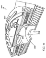
- Fig. 23 shows a perspective view, in part in section, of a single ink jet nozzle arrangement 401 constructed in accordance with an embodiment.
- an ink jet nozzle which incorporates a plunger that is surrounded by an electromagnetic device.
- the plunger is made from a magnetic material such that upon activation of the magnetic device, the plunger is forced towards a nozzle outlet port thereby resulting in the ejection of ink from the outlet port.
- the plunger Upon deactivation of the electromagnet, the plunger returns to its rest position via the utilisation of a series of springs constructed to return the electromagnet to its rest position.
- Fig. 42 illustrates a sectional view through a single ink jet nozzle 1310 as constructed with an embodiment.
- the ink jet nozzle 1310 includes a nozzle chamber 1311 which is connected to a nozzle output port 1312 for the ejection of ink.
- the ink is ejected by means of a tapered plunger device 1314 which is made of a soft magnetic material such as nickel-ferrous material (NIFE).
- the plunger 1314 includes tapered end portions, e.g. 1316, in addition to interconnecting nitride springs, e.g. 1317.
- An electromagnetic device is constructed around the plunger 1314 and includes outer soft magnetic material 1319 which surrounds a copper current carrying wire core 1320 with a first end of the copper coil 1320 connected to a first portion of a nickel- ferrous material and a second end of the copper coil is connected to a second portion of the nickel-ferrous material.
- the circuit being further formed by means of vias (not shown) connecting the current carrying wire to lower layers which can take the structure of standard CMOS fabrication layers.
- the tapered plunger portions 1316 Upon activation of the electromagnet, the tapered plunger portions 1316 attracted to the electromagnet.
- the tapering allows for the forces to be resolved by means of downward movement of the overall plunger 1314, the downward movement thereby causing the ejection of ink from ink ejection port 1312. In due course, the plunger will move to a stable state having a top surface substantially flush with the electromagnet.
- the plunger 1314 Upon turning the power off, the plunger 1314 will return to its original position as a result of energy stored within that nitride springs 1317.
- the nozzle chamber 1311 is refilled by inlet holes 1322 from the ink reservoir 1323.
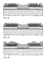
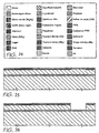
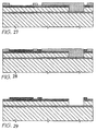
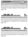
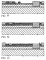
- Fig. 43 there is illustrated an exploded perspective of the various layers ulitized in construction of a single nozzle 1310.
- the bottom layer 1330 can be formed by back etching a silicon wafer which has a boron dope epitaxial layer as the etch stop.
- the boron dope layer 1330 can be further individually masked and etched so as to form nozzle rim 1331 and the nozzle ejection port 1312.
- a silicon layer 1332 is formed.
- the silicon layer 1332 can be formed as part of the original wafer having the buried boron doped layer 1330.
- the nozzle chamber proper can be formed substantially from high density low pressure plasma etching of the silicon layer 1332 so as to produce substantially vertical side walls thereby forming the nozzle chamber.
- a glass layered 1333 which can include the drive and control circuitry required for driving an array of nozzles 1310.
- the drive and control circuitry can comprise standard two level metal CMOS circuitry intra-connected to form the copper coil circuit by means of vias though upper layers (not shown).
- a nitride passivation layer 1334 is provided so as to passivate any lower glass layers, e.g. 1333, from sacrificial etches should a sacrificial etching be utilized in the formation of portions of the nozzle.
- nitride layer 1334 On top of the nitride layer 1334 is formed a first nickel-ferrous layer 1336 followed by a copper layer 1337 and a further nickel-ferrous layer 1338 which can be formed via a dual damascene process. On top of the layer 1338 is formed the final nitride spring layer 1340 with the springs being formed by means of semiconductor treatment of the nitride layer 1340 so as to release the springs in tension so as to thereby cause a slight rating of the plunger 1314. A number of techniques not disclosed in Fig. 228 can be utilized in the construction of various portions of the arrangement 1310.
- the nozzle chamber can be formed by utilizing the aforementioned plasma etch and then subsequently filling the nozzle chamber with sacrificial material such as glass so as to provide a support for the plunger 1314 with the plunger 1314 being subsequently released via sacrificial etching of the sacrificial layers.
- sacrificial material such as glass
- the tapered end portions of the nickel-ferrous material can be formed so that the utilisation of a half-tone mask having an intensity pattern corresponding to the desired bottom tapered profile of plunger 1314.
- the half-tone mask can be utilized to half-tone a resist so that the shape is transferred to the resist and subsequently to a lower layer, such as sacrificial glass on top of which is laid the nickel-ferrous material which can be finally planarised utilizing chemical mechanical planarization techniques.
- the presently disclosed ink jet printing technology is potentially suited to a wide range of printing system including: colour and monochrome office printers, short run digital printers, high speed digital printers, offset press supplemental printers, low cost scanning printers high speed pagewidth printers, notebook computers with inbuilt pagewidth printers, portable colour and monochrome printers, colour and monochrome copiers, colour and monochrome facsimile machines, combined printer, facsimile and copying machines, label printers, large format plotters, photograph copiers, printers for digital photographic "minilabs", video printers, PhotoCD printers, portable printers for PDAs, wallpaper printers, indoor sign printers, billboard printers, fabric printers, camera printers and fault tolerant commercial printer arrays.
- the embodiments of the invention use an ink jet printer type device. Of course many different devices could be used. However presently popular ink jet printing technologies are unlikely to be suitable.
- thermal inkjet The most significant problem with thermal inkjet is power consumption. This is approximately 100 times that required for high speed, and stems from the energy-inefficient means of drop ejection. This involves the rapid boiling of water to produce a vapor bubble which expels the ink. Water has a very high heat capacity, and must be superheated in thermal inkjet applications. This leads to an efficiency of around 0.02%, from electricity input to drop momentum (and increased surface area) out.
- piezoelectric inkjet The most significant problem with piezoelectric inkjet is size and cost. Piezoelectric crystals have a very small deflection at reasonable drive voltages, and therefore require a large area for each nozzle. Also, each piezoelectric actuator must be connected to its drive circuit on a separate substrate. This is not a significant problem at the current limit of around 300 nozzles per print head, but is a major impediment to the fabrication of pagewide print beads with 19,200 nozzles.
- the inktet technologies used meet the stringent requirements of in-camera digital color printing and other high quality, high speed, low cost printing applications.
- new inkjet technologies have been created.
- the target features include:
- inkjet designs shown here at suitable for a wide range of digital printing systems, from battery powered one-time use digital cameras, through to desktop and network printers, and through to commercial printing systems
- the print head is designed to be a monolithic 0.5 micron CMOS chip with MEMS post processing.
- the print head is 100 mm long, with a width which depends upon the inkjet type.
- the smallest print head designed is IJ38, which is 0.35 mm wide, giving a chip area of 35 square mm.
- the print heads each contain 19,200 nozzles plus data and control circuitry.
- Ink is supplied to the back of the print head by injection molded plastic ink channels.
- the molding requires 50 micron features, which can be created using a lithographically micromachined insert in a standard injection molding tool.
- Ink flows through holes etched through the wafer to the nozzle chambers fabricated on the front surface of the wafer.
- the print head is connected to the camera circuitry by tape automated bonding.
- inkjet configurations can readily be derived from these 45 examples by substituting alternative configurations along one or more of the 11 axes.
- Most of the IJ01 to IJ45 examples can be made into inkjet print heads with characteristics superior to any currently available inkjet technology.
- Suitable applications include: Home printers, Office network printers, Short run digital printers, Commercial print systems, Fabric printers, Pocket Printers, Internet WWW printers, Video printers, Medical imaging, Wide format printers, Notebook PC printers, Fax machines, Industrial printing systems, Photocopiers, Photographic minilabs etc.
- the present application may utilize advanced semiconductor fabrication techniques in the construction of large arrays of ink jet printers. Suitable manufacturing techniques are described in the following Australian provisional patent specifications incorporated here by cross-reference: Australian Provisional Number Filing Date Title PO7935 15-Jul-97 A Method of Manufacture of an Image Creation Apparatus (IJM01) PO7936 15-Jul-97 A Method of Manufacture of an Image Creation Apparatus (IJM02) PO7937 15-Jul-97 A Method of Manufacture of an Image Creation Apparatus (IJM03) PO8061 15-Jul-97 A Method of Manufacture of an Image Creation Apparatus (IJM04) PO8054 15-Jul-97 A Method of Manufacture of an Image Creation Apparatus (IJM05) PO8065 15-Jul-97 A Method of Manufacture of an Image Creation Apparatus (IJM06) PO8055 15-Jul-97 A Method of Manufacture of an Image Creation
- the present application may utilize an ink delivery system to the ink jet head.
- Delivery systems relating to the supply of ink to a series of ink jet nozzles are described in the following Australian provisional patent specifications, the disclosure of which are hereby incorporated by cross-reference: Australian Provisional Number Filing Date Title PO8003 15-Jul-97 Supply Method and Apparatus (F1) PO8005 15-Jul-97 Supply Method and Apparatus (F2) PO9404 23-Sep-97 A Device and Method (F3)
- the present application may utilize advanced semiconductor microelectromechanical techniques in the construction of large arrays of ink jet printers. Suitable microelectromechanical techniques are described in the following Australian provisional patent specifications incorporated here by cross-reference: Australian Provisional Number Filing Date Title PO7943 15-Jul-97 A device (MEMS01) PO8006 15-Jul-97 A device (MEMS02) PO8007 15-Jul-97 A device (MEMS03) PO8008 15-Jul-97 A device (MEMS04) PO8010 15-Jul-97 A device (MEMS05) PO8011 15-Jul-97 A device (MEMS06) PO7947 15-Jul-97 A device (MEMS07) PO7945 15-Jul-97 A device (MEMS08) PO7944 15-Jul-97 A device (MEMS09) PO7946 15-Jul-97 A device (MEMS10) PO9393 23-Sep-97 A Device and Method (MEMS11) PP0875 12-Dec-97 A Device
- the present application may include the utilization of a disposable camera system such as those described in the following Australian provisional patent specifications incorporated here by cross-reference: Australian Provisional Number Filing Date Title PP0895 12-Dec-97 An Image Creation Method and Apparatus (IR01) PP0870 12-Dec-97 A Device and Method (IR02) PP0869 12-Dec-97 A Device and Method (IR04) PP0887 12-Dec-97 Image Creation Method and Apparatus (IR05) PP0885 12-Dec-97 An Image Production System (IR06) PP0884 12-Dec-97 Image Creation Method and Apparatus (IR10) PP0886 12-Dec-97 Image Creation Method and Apparatus (IR12) PP0871 12-Dec-97 A Device and Method (IR13) PP0876 12-Dec-97 An Image Processing Method and Apparatus (IR14) PP0877 12-Dec-97 A Device and Method (IR16) PP0878 12-Dec-97 A Device and Method (IR17) PP08
- the present application may include the utilization of a data distribution system such as that described in the following Australian provisional patent specifications incorporated here by cross-reference: Australian Provisional Number Filing Date Title PP2370 16-Mar-98 Data Processing Method and Apparatus (Dot01) PP2371 16-Mar-98 Data Processing Method and Apparatus (Dot02)
- the present application may include the utilization of camera and data processing techniques such as an Artcam type device as described in the following Australian provisional patent specifications incorporated here by cross-reference: Australian Provisional Number Filing Date Title PO7991 15-Jul-97 Image Processing Method and Apparatus (ART01) PO8505 11-Aug-97 Image Processing Method and Apparatus (ART01a) PO7988 15-Jul-97 Image Processing Method and Apparatus (ART02) PO7993 15-Jul-97 Image Processing Method and Apparatus (ART03) PO8012 15-Jul-97 Image Processing Method and Apparatus (ART05) PO8017 15-Jul-97 Image Processing Method and Apparatus (ART06) PO8014 15-Jul-97 Media Device (ART07) PO8025 15-Jul-97 Image Processing Method and Apparatus (ART08) PO8032 15-Jul-97 Image Processing Method and Apparatus (ART09) PO7999 15-Jul-97 Image Processing Method and Apparatus (ART10) PO
Claims (21)
- Tintenstrahldruckdüsenanordnung, umfassenda) einen Tauchkern;b) eine elektrische Spule, die angrenzend an den Tauchkern angeordnet und elektrisch mit einem Düsenaktivierungssignal verbunden ist, worin nach Aktivierung des Aktivierungssignals der Tauchkern von der Spule veranlasst wird, sich von einer mit Tinte gefüllten Position zu einer Tintenausstoßposition zu bewegen, wodurch das Ausstoßen von Tinte von einer Tintenausstoßöffnung verursacht wird, dadurch gekennzeichnet, dass die Anordnung weiters Folgendes umfasst:i) eine Düsenkammer mit der Tintenausstoßöffnung an einem Ende; undii) eine Tintenkammer zur Ermöglichung der Zufuhr von Tinte zur Düsenkammer, wobei der Tauchkern aus einem weichmagnetischen Material gefertigt und zwischen der Düsenkammer und der Tintenkammer angeordnet ist.
- Tintenausströmdüsenanordnung nach Anspruch 1, wobei die Düsenanordnung weiters einen Anker, der aus einem weichmagnetischen Material gefertigt ist, umfasst, und worin der Tauchkern bei der Aktivierung der Spule zum Anker hin gezogen wird.
- Tintenstrahldruckdüsenanordnung nach Anspruch 1 oder Anspruch 2, worin die elektrische Spule in einem vom Tauchkern definierten Hohlraum angeordnet ist und worin die Maße des Hohlraums als Folge der Bewegung des Tauchkerns verkleinert werden, wobei der Tauchkern weiters eine Reihe an Fluidauslassschlitzen, die in Fluidkommunikation mit dem Hohlraum und der Tintenkammer stehen, aufweist, wobei die Fluidauslassschlitze einen Ausstoß eines Fluids unter Druck im Hohlraum zulassen.
- Tintenstrahldruckdüse nach Anspruch 3, worin die Schlitze um einen inneren Umfang der Spule herum definiert sind und die Schlitze ein im Wesentlichen konstantes Querschnittsprofil aufweisen.
- Tintenstrahldruckdüse nach Anspruch 4, worin die Schlitze radial an einer Oberfläche des Tauchkerns angeordnet sind.
- Tintenstrahldruckdüsenanordnung nach einem der Ansprüche 1 bis 5, wobei die Düsenanordnung weiters Federungsmittel zur Unterstützung des Tauchkerns bei der Rückkehr von der Tintenausstoßposition zur mit Tinte gefüllten Position nach dem Ausstoßen der Tinte aus der Tintenausstoßöffnung umfasst.
- Tintenstrahldruckdüsenanordnung nach Anspruch 6, worin das Federungsmittel eine Torsionsfeder umfasst.
- Tintenstrahldruckdüsenanordnung nach Anspruch 7, worin die Torsionsfeder gekrümmt konstruiert ist und ein im Wesentlichen gleiches Umfangsprofil wie jenes des Tauchkerns aufweist.
- Tintenstrahldruckdüsenvorrichtung nach einem der Ansprüche 6 bis 8, wobei das Federungsmittel angepasst ist, um den magnetischen Tauchkern nach der Deaktivierung der Aktivierungsspule zur ersten Position zurückzubewegen.
- Tintenstrahldruckdüsenvorrichtung nach einem der Ansprüche 6 bis 9, worin das Federungsmittel aus Siliciumnitrid hergestellt ist.
- Tintenstrahldruckdüsenvorrichtung nach einem der Ansprüche 1 bis 10, worin die Vorrichtung unter Verwendung von Halbleiterfertigungstechniken hergestellt ist.
- Tintenstrahldruckdüsenvorrichtung nach Anspruch 11, worin der Kolben und/oder die Spulen durch ein Dual-Damascene-Verfahren hergestellt sind.
- Tintenstrahldruckdüsenvorrichtung nach einem der Ansprüche 1 bis 12, worin die Tintenausstoßöffnung einen Düsenrand umfasst, der zur Verringerung der hydrophilen Oberflächenverteilung der Tinte angepasst ist.
- Tintenstrahldruckdüsenvorrichtung nach einem der Ansprüche 1 bis 13, worin die Aktivierungsspule durch ein Kupfer-Aufdampfverfahren hergestellt ist.
- Tintenstrahldüsenanordnung nach Anspruch 1, worin der Tauchkern im Wesentlichen kreisförmig ist und einen konischen Rand aufweist, der an Abschnitte der elektromagnetischen Einrichtung angrenzt.
- Tintenstrahldüsenanordnung nach Anspruch 1 oder Anspruch 15, worin die elektromagnetische Einrichtung torusförmig ist und der Tauchkern in der Mitte des Torus angeordnet ist.
- Tintenstrahldüsenanordnung nach Anspruch 15 oder Anspruch 16, worin der Tauchkern weiters mit einem Federungsmittel verbunden ist, das die Rückkehr des Tauchkerns nach der Deaktivierung der Aktivierungsspule zur Ausgangsposition zulässt.
- Tintenstrahldüsenanordnung nach Anspruch 17, worin das Federungsmittel eine Reihe von Federn ist.
- Tintenstrahldüsenanordnung nach Anspruch 18, worin die Federn mit einem zentralen Abschnitt des Tauchkerns verbunden sind und radial in Spiralform zu den Seitenwänden hin verlaufen.
- Tintenstrahldüsenanordnung nach Anspruch 17 oder Anspruch 18, worin die Federn durch Spannungsentlastung von aufgedampftem Material gebildet sind.
- Tintenstrahldüsenanordnung nach Anspruch 20, worin das aufgedampfte Material Nitrid umfasst.
Priority Applications (10)
| Application Number | Priority Date | Filing Date | Title |
|---|---|---|---|
| EP04024064A EP1508445B1 (de) | 1997-07-15 | 1998-07-15 | Tintenstrahldüse mit Lorentz-Kraft-Element |
| EP04024065A EP1510341B1 (de) | 1997-07-15 | 1998-07-15 | Tintenstrahldüse mit elektromagnetischem Verschluss |
| EP04024058A EP1508444B1 (de) | 1997-07-15 | 1998-07-15 | Tintenstrahldrucker mit elektrostatisch betätigten Platten |
| EP04024057A EP1508443B1 (de) | 1997-07-15 | 1998-07-15 | Tintenstrahldüse mit elektromagnetisch aktiviertem Tintenkolben |
| EP04024063A EP1510340B1 (de) | 1997-07-15 | 1998-07-15 | Tintenstrahldüse mit geschlitztem Kolben |
| EP04024061A EP1508448B1 (de) | 1997-07-15 | 1998-07-15 | Tintenstrahldüse mit angeschrägtem magnetischen Kolben |
| EP04024060A EP1510339B1 (de) | 1997-07-15 | 1998-07-15 | Durch magnetische Impulse betriebene Tintenstrahldüse |
| EP04024066A EP1508446B1 (de) | 1997-07-15 | 1998-07-15 | Tintenstrahldüse mit elektromagnetischem Betätigungselement |
| EP04024059A EP1512535B1 (de) | 1997-07-15 | 1998-07-15 | Tintenstrahldrucker mit magnetisch angetriebenem Kolben |
| EP04024062A EP1508449B1 (de) | 1997-07-15 | 1998-07-15 | Tintenstrahldüse mit magnetischer Antriebskammer |
Applications Claiming Priority (73)
| Application Number | Priority Date | Filing Date | Title |
|---|---|---|---|
| AUPO8055A AUPO805597A0 (en) | 1997-07-15 | 1997-07-15 | A method of manufacture of an image creation apparatus (IJM07) |
| AUPO8076A AUPO807697A0 (en) | 1997-07-15 | 1997-07-15 | A method of manufacture of an image creation apparatus (IJM16) |
| AUPO805697 | 1997-07-15 | ||
| AUPO8067A AUPO806797A0 (en) | 1997-07-15 | 1997-07-15 | Image creation method and apparatus (IJ16) |
| AUPO807697 | 1997-07-15 | ||
| AUPO7933A AUPO793397A0 (en) | 1997-07-15 | 1997-07-15 | A method of manufacture of an image creation_apparatus (IJM10) |
| AUPO8004A AUPO800497A0 (en) | 1997-07-15 | 1997-07-15 | Image creation method and apparatus (IJ26) |
| AUPO806697 | 1997-07-15 | ||
| AUPO8047A AUPO804797A0 (en) | 1997-07-15 | 1997-07-15 | Image creation method and apparatus (IJ05) |
| AUPO8048A AUPO804897A0 (en) | 1997-07-15 | 1997-07-15 | Image creation method and apparatus (IJ14) |
| AUPO8077A AUPO807797A0 (en) | 1997-07-15 | 1997-07-15 | A method of manufacture of an image creation apparatus (IJM25) |
| AUPO805397 | 1997-07-15 | ||
| AUPO8060A AUPO806097A0 (en) | 1997-07-15 | 1997-07-15 | A method of manufacture of an image creation apparatus (IJM13) |
| AUPO804497 | 1997-07-15 | ||
| AUPO8073A AUPO807397A0 (en) | 1997-07-15 | 1997-07-15 | A method of manufacture of an image creation apparatus (IJM15) |
| AUPO803697 | 1997-07-15 | ||
| AUPO8058A AUPO805897A0 (en) | 1997-07-15 | 1997-07-15 | A method of manufacture of an image creation apparatus (IJM26) |
| AUPO8061A AUPO806197A0 (en) | 1997-07-15 | 1997-07-15 | A method of manufacture of an image creation apparatus (IJM04) |
| AUPO8001A AUPO800197A0 (en) | 1997-07-15 | 1997-07-15 | Image creation method and apparatus (IJ17) |
| AUPO794997 | 1997-07-15 | ||
| AUPO804197 | 1997-07-15 | ||
| AUPO805897 | 1997-07-15 | ||
| AUPO805497 | 1997-07-15 | ||
| AUPO8054A AUPO805497A0 (en) | 1997-07-15 | 1997-07-15 | A method of manufacture of an image creation apparatus (IJM05) |
| AUPO793397 | 1997-07-15 | ||
| AUPO793597 | 1997-07-15 | ||
| AUPO8049A AUPO804997A0 (en) | 1997-07-15 | 1997-07-15 | Image creation method and apparatus (IJ12) |
| AUPO8041A AUPO804197A0 (en) | 1997-07-15 | 1997-07-15 | Image creation method and apparatus (IJ25) |
| AUPO795097 | 1997-07-15 | ||
| AUPO8035A AUPO803597A0 (en) | 1997-07-15 | 1997-07-15 | Image creation method and apparatus (IJ06) |
| AUPO807097 | 1997-07-15 | ||
| AUPO806597 | 1997-07-15 | ||
| AUPO8070A AUPO807097A0 (en) | 1997-07-15 | 1997-07-15 | Image creation method and apparatus (IJ15) |
| AUPO8044A AUPO804497A0 (en) | 1997-07-15 | 1997-07-15 | Image creation method and apparatus (IJ07) |
| AUPO8059A AUPO805997A0 (en) | 1997-07-15 | 1997-07-15 | A method of manufacture of an image creation apparatus (IJM14) |
| AUPO7936A AUPO793697A0 (en) | 1997-07-15 | 1997-07-15 | A method of manufacture of an image creation apparatus (IJM02) |
| AUPO8053A AUPO805397A0 (en) | 1997-07-15 | 1997-07-15 | A method of manufacture of an image creation apparatus (IJM08) |
| AUPO807797 | 1997-07-15 | ||
| AUPO800197 | 1997-07-15 | ||
| AUPO8075A AUPO807597A0 (en) | 1997-07-15 | 1997-07-15 | A method of manufacture of an image creation apparatus (IJM17) |
| AUPO7949A AUPO794997A0 (en) | 1997-07-15 | 1997-07-15 | A method of manufacture of an image creation apparatus (IJM12) |
| AUPO807297 | 1997-07-15 | ||
| AUPO8056A AUPO805697A0 (en) | 1997-07-15 | 1997-07-15 | Image creation method and apparatus (IJ10) |
| AUPO7935A AUPO793597A0 (en) | 1997-07-15 | 1997-07-15 | A method of manufacture of an image creation apparatus (IJM01) |
| AUPO8071A AUPO807197A0 (en) | 1997-07-15 | 1997-07-15 | Image creation method and apparatus (IJ04) |
| AUPO807397 | 1997-07-15 | ||
| AUPO804897 | 1997-07-15 | ||
| AUPO806997 | 1997-07-15 | ||
| AUPO806797 | 1997-07-15 | ||
| AUPO793697 | 1997-07-15 | ||
| AUPO804797 | 1997-07-15 | ||
| AUPO8036A AUPO803697A0 (en) | 1997-07-15 | 1997-07-15 | Image creation method and apparatus (IJ13) |
| AUPO8066A AUPO806697A0 (en) | 1997-07-15 | 1997-07-15 | Image creation method and apparatus (IJ01) |
| AUPO805997 | 1997-07-15 | ||
| AUPO8065A AUPO806597A0 (en) | 1997-07-15 | 1997-07-15 | A method of manufacture of an image creation apparatus (IJM06) |
| AUPO7950A AUPO795097A0 (en) | 1997-07-15 | 1997-07-15 | A method of manufacture of an image creation apparatus (IJM11) |
| AUPO8069A AUPO806997A0 (en) | 1997-07-15 | 1997-07-15 | Image creation method and apparatus (IJ11) |
| AUPO804997 | 1997-07-15 | ||
| AUPO807597 | 1997-07-15 | ||
| AUPO806197 | 1997-07-15 | ||
| AUPO800497 | 1997-07-15 | ||
| AUPO803597 | 1997-07-15 | ||
| AUPO8072A AUPO807297A0 (en) | 1997-07-15 | 1997-07-15 | Image creation method and apparatus (IJ02) |
| AUPO806097 | 1997-07-15 | ||
| AUPO805597 | 1997-07-15 | ||
| AUPO806397 | 1997-07-15 | ||
| AUPO807197 | 1997-07-15 | ||
| AUPO8063A AUPO806397A0 (en) | 1997-07-15 | 1997-07-15 | Image creation method and apparatus (IJ08) |
| AUPP3982A AUPP398298A0 (en) | 1998-06-09 | 1998-06-09 | A method of manufacture of an image creation apparatus (ijm45) |
| AUPP398398 | 1998-06-09 | ||
| AUPP3983A AUPP398398A0 (en) | 1998-06-09 | 1998-06-09 | Image creation method and apparatus (ij45) |
| AUPP398298 | 1998-06-09 | ||
| PCT/AU1998/000548 WO1999003680A1 (en) | 1997-07-15 | 1998-07-15 | A field acutated ink jet |
Related Child Applications (20)
| Application Number | Title | Priority Date | Filing Date |
|---|---|---|---|
| EP04024063A Division EP1510340B1 (de) | 1997-07-15 | 1998-07-15 | Tintenstrahldüse mit geschlitztem Kolben |
| EP04024059A Division EP1512535B1 (de) | 1997-07-15 | 1998-07-15 | Tintenstrahldrucker mit magnetisch angetriebenem Kolben |
| EP04024064A Division EP1508445B1 (de) | 1997-07-15 | 1998-07-15 | Tintenstrahldüse mit Lorentz-Kraft-Element |
| EP04024057A Division EP1508443B1 (de) | 1997-07-15 | 1998-07-15 | Tintenstrahldüse mit elektromagnetisch aktiviertem Tintenkolben |
| EP04024066A Division EP1508446B1 (de) | 1997-07-15 | 1998-07-15 | Tintenstrahldüse mit elektromagnetischem Betätigungselement |
| EP04024061A Division EP1508448B1 (de) | 1997-07-15 | 1998-07-15 | Tintenstrahldüse mit angeschrägtem magnetischen Kolben |
| EP04024060A Division EP1510339B1 (de) | 1997-07-15 | 1998-07-15 | Durch magnetische Impulse betriebene Tintenstrahldüse |
| EP04024065A Division EP1510341B1 (de) | 1997-07-15 | 1998-07-15 | Tintenstrahldüse mit elektromagnetischem Verschluss |
| EP04024058A Division EP1508444B1 (de) | 1997-07-15 | 1998-07-15 | Tintenstrahldrucker mit elektrostatisch betätigten Platten |
| EP04024062A Division EP1508449B1 (de) | 1997-07-15 | 1998-07-15 | Tintenstrahldüse mit magnetischer Antriebskammer |
| EP04024060.8 Division-Into | 2004-10-08 | ||
| EP04024064.0 Division-Into | 2004-10-08 | ||
| EP04024057.4 Division-Into | 2004-10-08 | ||
| EP04024066.5 Division-Into | 2004-10-08 | ||
| EP04024059.0 Division-Into | 2004-10-08 | ||
| EP04024058.2 Division-Into | 2004-10-08 | ||
| EP04024065.7 Division-Into | 2004-10-08 | ||
| EP04024061.6 Division-Into | 2004-10-08 | ||
| EP04024063.2 Division-Into | 2004-10-08 | ||
| EP04024062.4 Division-Into | 2004-10-08 |
Publications (3)
| Publication Number | Publication Date |
|---|---|
| EP0999933A1 EP0999933A1 (de) | 2000-05-17 |
| EP0999933A4 EP0999933A4 (de) | 2000-12-20 |
| EP0999933B1 true EP0999933B1 (de) | 2005-03-02 |
Family
ID=27586944
Family Applications (11)
| Application Number | Title | Priority Date | Filing Date |
|---|---|---|---|
| EP04024060A Expired - Lifetime EP1510339B1 (de) | 1997-07-15 | 1998-07-15 | Durch magnetische Impulse betriebene Tintenstrahldüse |
| EP04024065A Expired - Lifetime EP1510341B1 (de) | 1997-07-15 | 1998-07-15 | Tintenstrahldüse mit elektromagnetischem Verschluss |
| EP04024063A Expired - Lifetime EP1510340B1 (de) | 1997-07-15 | 1998-07-15 | Tintenstrahldüse mit geschlitztem Kolben |
| EP04024059A Expired - Lifetime EP1512535B1 (de) | 1997-07-15 | 1998-07-15 | Tintenstrahldrucker mit magnetisch angetriebenem Kolben |
| EP04024066A Expired - Lifetime EP1508446B1 (de) | 1997-07-15 | 1998-07-15 | Tintenstrahldüse mit elektromagnetischem Betätigungselement |
| EP04024058A Expired - Lifetime EP1508444B1 (de) | 1997-07-15 | 1998-07-15 | Tintenstrahldrucker mit elektrostatisch betätigten Platten |
| EP04024062A Expired - Lifetime EP1508449B1 (de) | 1997-07-15 | 1998-07-15 | Tintenstrahldüse mit magnetischer Antriebskammer |
| EP04024061A Expired - Lifetime EP1508448B1 (de) | 1997-07-15 | 1998-07-15 | Tintenstrahldüse mit angeschrägtem magnetischen Kolben |
| EP98933350A Expired - Lifetime EP0999933B1 (de) | 1997-07-15 | 1998-07-15 | Magnetfeld-betätigte tintenstrahldüse |
| EP04024064A Expired - Lifetime EP1508445B1 (de) | 1997-07-15 | 1998-07-15 | Tintenstrahldüse mit Lorentz-Kraft-Element |
| EP04024057A Expired - Lifetime EP1508443B1 (de) | 1997-07-15 | 1998-07-15 | Tintenstrahldüse mit elektromagnetisch aktiviertem Tintenkolben |
Family Applications Before (8)
| Application Number | Title | Priority Date | Filing Date |
|---|---|---|---|
| EP04024060A Expired - Lifetime EP1510339B1 (de) | 1997-07-15 | 1998-07-15 | Durch magnetische Impulse betriebene Tintenstrahldüse |
| EP04024065A Expired - Lifetime EP1510341B1 (de) | 1997-07-15 | 1998-07-15 | Tintenstrahldüse mit elektromagnetischem Verschluss |
| EP04024063A Expired - Lifetime EP1510340B1 (de) | 1997-07-15 | 1998-07-15 | Tintenstrahldüse mit geschlitztem Kolben |
| EP04024059A Expired - Lifetime EP1512535B1 (de) | 1997-07-15 | 1998-07-15 | Tintenstrahldrucker mit magnetisch angetriebenem Kolben |
| EP04024066A Expired - Lifetime EP1508446B1 (de) | 1997-07-15 | 1998-07-15 | Tintenstrahldüse mit elektromagnetischem Betätigungselement |
| EP04024058A Expired - Lifetime EP1508444B1 (de) | 1997-07-15 | 1998-07-15 | Tintenstrahldrucker mit elektrostatisch betätigten Platten |
| EP04024062A Expired - Lifetime EP1508449B1 (de) | 1997-07-15 | 1998-07-15 | Tintenstrahldüse mit magnetischer Antriebskammer |
| EP04024061A Expired - Lifetime EP1508448B1 (de) | 1997-07-15 | 1998-07-15 | Tintenstrahldüse mit angeschrägtem magnetischen Kolben |
Family Applications After (2)
| Application Number | Title | Priority Date | Filing Date |
|---|---|---|---|
| EP04024064A Expired - Lifetime EP1508445B1 (de) | 1997-07-15 | 1998-07-15 | Tintenstrahldüse mit Lorentz-Kraft-Element |
| EP04024057A Expired - Lifetime EP1508443B1 (de) | 1997-07-15 | 1998-07-15 | Tintenstrahldüse mit elektromagnetisch aktiviertem Tintenkolben |
Country Status (4)
| Country | Link |
|---|---|
| EP (11) | EP1510339B1 (de) |
| JP (6) | JP4170582B2 (de) |
| AT (8) | ATE352423T1 (de) |
| WO (1) | WO1999003680A1 (de) |
Families Citing this family (57)
| Publication number | Priority date | Publication date | Assignee | Title |
|---|---|---|---|---|
| US6659593B1 (en) | 2000-04-18 | 2003-12-09 | Silverbrook Research Pty Ltd | Ink jet ejector |
| US7753491B2 (en) | 1997-07-15 | 2010-07-13 | Silverbrook Research Pty Ltd | Printhead nozzle arrangement incorporating a corrugated electrode |
| US6855264B1 (en) | 1997-07-15 | 2005-02-15 | Kia Silverbrook | Method of manufacture of an ink jet printer having a thermal actuator comprising an external coil spring |
| US7328975B2 (en) * | 1997-07-15 | 2008-02-12 | Silverbrook Research Pty Ltd | Injet printhead with thermal bend arm exposed to ink flow |
| AUPP654598A0 (en) | 1998-10-16 | 1998-11-05 | Silverbrook Research Pty Ltd | Micromechanical device and method (ij46h) |
| US7410243B2 (en) * | 1997-07-15 | 2008-08-12 | Silverbrook Research Pty Ltd | Inkjet nozzle with resiliently biased ejection actuator |
| US7360871B2 (en) * | 1997-07-15 | 2008-04-22 | Silverbrook Research Pty Ltd | Inkjet chamber with ejection actuator between inlet and nozzle |
| AUPP922399A0 (en) * | 1999-03-16 | 1999-04-15 | Silverbrook Research Pty Ltd | A method and apparatus (ij46p2) |
| AUPP993099A0 (en) * | 1999-04-22 | 1999-05-20 | Silverbrook Research Pty Ltd | A micromechancial device and method(ij46p2b) |
| AU2004202252B2 (en) * | 1999-04-22 | 2005-06-30 | Silverbrook Research Pty Ltd | Liquid ejection using a micro-electromechanical device |
| EP1206351B1 (de) * | 1999-06-30 | 2008-07-09 | Silverbrook Research Pty. Limited | Prüfung einer mikroelektromechanischen vorrichtung |
| AUPQ130999A0 (en) | 1999-06-30 | 1999-07-22 | Silverbrook Research Pty Ltd | A method and apparatus (IJ47V11) |
| US6382779B1 (en) | 1999-06-30 | 2002-05-07 | Silverbrook Research Pty Ltd | Testing a micro electro- mechanical device |
| AU761670B2 (en) * | 1999-06-30 | 2003-06-05 | Silverbrook Research Pty Ltd | Testing a micro electro-mechanical device |
| AU761820B2 (en) * | 1999-06-30 | 2003-06-12 | Silverbrook Research Pty Ltd | Calibrating a micro electro-mechanical device |
| AU761821B2 (en) * | 1999-06-30 | 2003-06-12 | Silverbrook Research Pty Ltd | Fault detection in a micro electro-mechanical device |
| KR100752253B1 (ko) | 1999-09-17 | 2007-08-29 | 실버브룩 리서치 피티와이 리미티드 | 컴퓨터의 명령을 위한 방법 및 시스템 |
| US7287839B2 (en) | 2002-08-19 | 2007-10-30 | Silverbrook Research Pty Ltd | Inkjet printhead having bicuspid valved ink ejection arrangement |
| US6557970B2 (en) | 2000-05-23 | 2003-05-06 | Silverbrook Research Pty Ltd | Nozzle guard for a printhead |
| US6921153B2 (en) | 2000-05-23 | 2005-07-26 | Silverbrook Research Pty Ltd | Liquid displacement assembly including a fluidic sealing structure |
| US6428133B1 (en) | 2000-05-23 | 2002-08-06 | Silverbrook Research Pty Ltd. | Ink jet printhead having a moving nozzle with an externally arranged actuator |
| US6526658B1 (en) | 2000-05-23 | 2003-03-04 | Silverbrook Research Pty Ltd | Method of manufacture of an ink jet printhead having a moving nozzle with an externally arranged actuator |
| CN100417523C (zh) * | 2000-05-24 | 2008-09-10 | 西尔弗布鲁克研究有限公司 | 带有隔离的喷嘴控制器的喷墨打印头 |
| AU2000247326B2 (en) * | 2000-05-24 | 2004-03-18 | Memjet Technology Limited | Fluidic seal for an ink jet nozzle assembly |
| US7152962B1 (en) | 2000-05-24 | 2006-12-26 | Silverbrook Research Pty Ltd | Ink jet printhead having a moving nozzle with an externally arranged actuator |
| AU2000247314C1 (en) | 2000-05-24 | 2005-10-06 | Zamtec Limited | Method of manufacture of an ink jet printhead having a moving nozzle with an externally arranged actuator |
| US6364460B1 (en) | 2000-06-13 | 2002-04-02 | Chad R. Sager | Liquid delivery system |
| AU2006225215B2 (en) * | 2000-06-30 | 2009-04-09 | Zamtec Limited | An ink ejector for an inkjet printer with an arm and paddle arrangement |
| EP1301346B1 (de) * | 2000-06-30 | 2007-08-15 | Silverbrook Research Pty. Limited | Knickresistente, thermisch biegende betätiger |
| AU5373900A (en) * | 2000-06-30 | 2002-01-14 | Silverbrook Res Pty Ltd | Buckle resistant thermal bend actuators |
| SG165980A1 (en) * | 2000-06-30 | 2010-11-29 | Silverbrook Res Pty Ltd | A micro-electromechanical actuator with buckle-resistant properties |
| US6863379B2 (en) | 2002-11-23 | 2005-03-08 | Silverbrook Research Pty Ltd | Ink jet printhead that includes nozzles having pressure-enhancing formations |
| AU2004203502B2 (en) * | 2000-10-20 | 2004-09-30 | Zamtec Limited | Nozzle for an ink jet printhead |
| US7066577B2 (en) | 2004-07-19 | 2006-06-27 | Silverbrook Research Pty Ltd | Pressure enhancing formations in an ink jet printhead |
| US6406129B1 (en) * | 2000-10-20 | 2002-06-18 | Silverbrook Research Pty Ltd | Fluidic seal for moving nozzle ink jet |
| US6505916B1 (en) | 2000-10-20 | 2003-01-14 | Silverbrook Research Pty Ltd | Nozzle poker for moving nozzle ink jet |
| US6623101B1 (en) | 2000-10-20 | 2003-09-23 | Silverbrook Research Pty Ltd | Moving nozzle ink jet |
| US6350015B1 (en) * | 2000-11-24 | 2002-02-26 | Xerox Corporation | Magnetic drive systems and methods for a micromachined fluid ejector |
| US6561627B2 (en) * | 2000-11-30 | 2003-05-13 | Eastman Kodak Company | Thermal actuator |
| US6508947B2 (en) * | 2001-01-24 | 2003-01-21 | Xerox Corporation | Method for fabricating a micro-electro-mechanical fluid ejector |
| US6572218B2 (en) * | 2001-01-24 | 2003-06-03 | Xerox Corporation | Electrostatically-actuated device having a corrugated multi-layer membrane structure |
| KR100757363B1 (ko) * | 2002-11-21 | 2007-09-11 | 실버브룩 리서치 피티와이 리미티드 | 유체씨일을 구비한 잉크 젯 노즐 조립체 |
| JP3912267B2 (ja) * | 2002-11-29 | 2007-05-09 | ソニー株式会社 | 液滴吐出装置、検査用チップ処理装置、液滴吐出方法、検査用チップ処理方法 |
| KR20090068236A (ko) | 2006-09-08 | 2009-06-25 | 메사추세츠 인스티튜트 오브 테크놀로지 | 자동화된 층상 분무 기법 |
| KR100973979B1 (ko) * | 2008-08-22 | 2010-08-05 | 한국과학기술원 | 전자기력을 이용한 다축 구동기 |
| KR102022392B1 (ko) * | 2012-12-11 | 2019-11-05 | 삼성디스플레이 주식회사 | 노즐프린터 |
| KR20140094957A (ko) | 2013-01-23 | 2014-07-31 | 삼성디스플레이 주식회사 | 노즐프린터용 노즐유닛 및 이를 구비하는 노즐프린터 |
| CN104401129B (zh) * | 2014-11-21 | 2016-08-24 | 常俊环 | 大字符喷码机喷头 |
| DE102015225726A1 (de) * | 2015-12-17 | 2017-06-22 | Ksb Aktiengesellschaft | Pumpe mit verformbarem Förderelement |
| US10589980B2 (en) * | 2017-04-07 | 2020-03-17 | Texas Instruments Incorporated | Isolated protrusion/recession features in a micro electro mechanical system |
| CN109144885B (zh) * | 2017-06-27 | 2022-04-29 | 北京忆恒创源科技股份有限公司 | 固态存储设备的垃圾回收方法与固态存储设备 |
| GB2573117B (en) | 2018-04-24 | 2021-02-17 | Adey Holdings 2008 Ltd | Magnetic filter |
| KR20200085510A (ko) * | 2019-01-07 | 2020-07-15 | 에스케이하이닉스 주식회사 | 데이터 저장 장치 및 동작 방법과, 이를 위한 컨트롤러 |
| CN110389317B (zh) * | 2019-06-03 | 2021-08-10 | 广州南盾通讯设备有限公司 | 一种对散序对象快速定位的低功耗柜体及定位方法 |
| CN112652529B (zh) * | 2019-10-09 | 2022-03-22 | 长鑫存储技术有限公司 | 半导体器件及半导体器件的电容孔制备方法 |
| CN112787237B (zh) * | 2021-01-16 | 2023-06-23 | 四川省盛源鑫智能电气有限责任公司 | 基于拨动机构的电气自动化控制柜 |
| CN113607122B (zh) * | 2021-08-23 | 2022-11-25 | 中国建筑第八工程局有限公司 | 箱型钢板墙内部校正用的智能小车、设备及方法 |
Family Cites Families (33)
| Publication number | Priority date | Publication date | Assignee | Title |
|---|---|---|---|---|
| US4032929A (en) * | 1975-10-28 | 1977-06-28 | Xerox Corporation | High density linear array ink jet assembly |
| DE2700010A1 (de) * | 1976-01-15 | 1977-07-21 | Xerox Corp | Geraet zur erzeugung von abtrennbaren fluessigkeitstroepfchen und antriebselemente dafuer |
| JPS5559972A (en) * | 1978-10-28 | 1980-05-06 | Seiko Epson Corp | Ink jet recording head |
| US4210920A (en) * | 1979-01-31 | 1980-07-01 | The Mead Corporation | Magnetically activated plane wave stimulator |
| US4460905A (en) * | 1982-03-29 | 1984-07-17 | Ncr Corporation | Control valve for ink jet nozzles |
| DE3245283A1 (de) * | 1982-12-07 | 1984-06-07 | Siemens AG, 1000 Berlin und 8000 München | Anordnung zum ausstoss von fluessigkeitstroepfchen |
| DE3302617A1 (de) * | 1983-01-27 | 1984-08-02 | Cyklop International Emil Hoffmann KG, 5000 Köln | Farbspritzkopf |
| JPS60131254A (ja) * | 1983-12-20 | 1985-07-12 | Ricoh Co Ltd | インクジエツト噴射ヘツド |
| DE3445720A1 (de) * | 1984-12-14 | 1986-06-19 | Siemens AG, 1000 Berlin und 8000 München | Anordnung zum ausstoss von einzeltroepfchen aus austrittsoeffnungen eines tintenschreibkopfes |
| SE447222B (sv) * | 1984-12-21 | 1986-11-03 | Swedot System Ab | Elektromagnetiskt manovrerbar ventilanordning, serskilt for alstring av droppar i en vetskestralskrivare |
| US4618808A (en) * | 1985-01-30 | 1986-10-21 | International Business Machines Corporation | Electromagnetic actuator system using stepper motor with closed loop position sensing, electronic commutation and dynamic position and anomaly correction |
| GB8507688D0 (en) * | 1985-03-25 | 1985-05-01 | Lane International Ltd John | Fluid applicator |
| US4723131A (en) * | 1986-09-12 | 1988-02-02 | Diagraph Corporation | Printhead for ink jet printing apparatus |
| JPH0234342A (ja) * | 1988-07-25 | 1990-02-05 | Seiko Epson Corp | インクジェットヘッド |
| JPH02150353A (ja) * | 1988-11-30 | 1990-06-08 | Nec Home Electron Ltd | インクジェットヘッド |
| GB8828047D0 (en) * | 1988-12-01 | 1989-01-05 | Willett Int Ltd | Method of operating valve |
| JPH02219655A (ja) * | 1989-02-20 | 1990-09-03 | Sharp Corp | インクジェットヘッド |
| JPH02273241A (ja) * | 1989-04-14 | 1990-11-07 | Ricoh Co Ltd | インクジェット記録装置 |
| JPH0365349A (ja) * | 1989-08-03 | 1991-03-20 | Matsushita Electric Ind Co Ltd | インクジェットヘッド |
| JP2839345B2 (ja) * | 1989-09-11 | 1998-12-16 | 松下電器産業株式会社 | インク記録装置 |
| JPH04126255A (ja) * | 1990-09-18 | 1992-04-27 | Seiko Epson Corp | インクジェットヘッド |
| US5534900A (en) * | 1990-09-21 | 1996-07-09 | Seiko Epson Corporation | Ink-jet recording apparatus |
| JPH04129745A (ja) * | 1990-09-21 | 1992-04-30 | Seiko Epson Corp | インクジェットヘッド |
| JPH04357039A (ja) * | 1991-06-03 | 1992-12-10 | Rohm Co Ltd | インクジェットプリントヘッド |
| JPH04368851A (ja) * | 1991-06-17 | 1992-12-21 | Seiko Epson Corp | 磁場発生基板及びそれを用いたインクジェットヘッド |
| GB9121851D0 (en) * | 1991-10-15 | 1991-11-27 | Willett Int Ltd | Device |
| DE4139731A1 (de) * | 1991-12-03 | 1993-06-09 | Inno-Print Verpackungs- + Beschriftungssysteme Gmbh, 5060 Bergisch Gladbach, De | Tintenstrahl-matrixdrucker aus einzelelementen |
| JPH05318724A (ja) * | 1992-05-19 | 1993-12-03 | Seikosha Co Ltd | インクジェット記録装置 |
| JPH06106725A (ja) * | 1992-08-14 | 1994-04-19 | Ricoh Co Ltd | 静電変形型インクジェットによる記録方法及び静電変形型インクジェットヘッド |
| JPH06134985A (ja) * | 1992-10-28 | 1994-05-17 | Ricoh Co Ltd | 1ドット多値が可能な記録装置及び1ドット多値が可能な記録方法 |
| JPH06336011A (ja) * | 1993-05-31 | 1994-12-06 | Sharp Corp | プリントヘッド装置 |
| DE69517720T2 (de) * | 1994-03-09 | 2001-02-01 | Seiko Epson Corp | Tintenstrahlaufzeichnungsgerät |
| US5828394A (en) * | 1995-09-20 | 1998-10-27 | The Board Of Trustees Of The Leland Stanford Junior University | Fluid drop ejector and method |
-
1998
- 1998-07-15 JP JP2000502941A patent/JP4170582B2/ja not_active Expired - Fee Related
- 1998-07-15 EP EP04024060A patent/EP1510339B1/de not_active Expired - Lifetime
- 1998-07-15 EP EP04024065A patent/EP1510341B1/de not_active Expired - Lifetime
- 1998-07-15 WO PCT/AU1998/000548 patent/WO1999003680A1/en active IP Right Grant
- 1998-07-15 EP EP04024063A patent/EP1510340B1/de not_active Expired - Lifetime
- 1998-07-15 EP EP04024059A patent/EP1512535B1/de not_active Expired - Lifetime
- 1998-07-15 AT AT04024062T patent/ATE352423T1/de not_active IP Right Cessation
- 1998-07-15 AT AT98933350T patent/ATE289922T1/de not_active IP Right Cessation
- 1998-07-15 EP EP04024066A patent/EP1508446B1/de not_active Expired - Lifetime
- 1998-07-15 AT AT04024060T patent/ATE352420T1/de not_active IP Right Cessation
- 1998-07-15 EP EP04024058A patent/EP1508444B1/de not_active Expired - Lifetime
- 1998-07-15 EP EP04024062A patent/EP1508449B1/de not_active Expired - Lifetime
- 1998-07-15 AT AT04024059T patent/ATE381991T1/de not_active IP Right Cessation
- 1998-07-15 AT AT04024063T patent/ATE352421T1/de not_active IP Right Cessation
- 1998-07-15 EP EP04024061A patent/EP1508448B1/de not_active Expired - Lifetime
- 1998-07-15 AT AT04024065T patent/ATE352422T1/de not_active IP Right Cessation
- 1998-07-15 AT AT04024064T patent/ATE353053T1/de not_active IP Right Cessation
- 1998-07-15 EP EP98933350A patent/EP0999933B1/de not_active Expired - Lifetime
- 1998-07-15 EP EP04024064A patent/EP1508445B1/de not_active Expired - Lifetime
- 1998-07-15 AT AT04024057T patent/ATE355972T1/de not_active IP Right Cessation
- 1998-07-15 EP EP04024057A patent/EP1508443B1/de not_active Expired - Lifetime
-
2006
- 2006-10-02 JP JP2006270743A patent/JP4137964B2/ja not_active Expired - Fee Related
- 2006-10-02 JP JP2006270831A patent/JP4173174B2/ja not_active Expired - Fee Related
- 2006-10-02 JP JP2006270974A patent/JP4137965B2/ja not_active Expired - Fee Related
- 2006-10-02 JP JP2006270641A patent/JP4171037B2/ja not_active Expired - Fee Related
- 2006-10-02 JP JP2006270310A patent/JP4185538B2/ja not_active Expired - Fee Related
Also Published As
Similar Documents
| Publication | Publication Date | Title |
|---|---|---|
| EP0999933B1 (de) | Magnetfeld-betätigte tintenstrahldüse | |
| US6195150B1 (en) | Pseudo-3D stereoscopic images and output device | |
| EP0999934B1 (de) | Thermisch betätigter tintenstrahl | |
| US6188415B1 (en) | Ink jet printer having a thermal actuator comprising an external coil spring | |
| US6067797A (en) | Thermal actuator | |
| US6041600A (en) | Utilization of quantum wires in MEMS actuators | |
| US6044646A (en) | Micro cilia array and use thereof | |
| US6087638A (en) | Corrugated MEMS heater structure | |
| US7086724B2 (en) | Compact media and ink cartridge for inkjet printhead | |
| US7576794B2 (en) | Manipulation of digital camera images utilizing stored autofocus settings | |
| US8902333B2 (en) | Image processing method using sensed eye position | |
| US6690416B1 (en) | Image production utilizing text editing including complex character sets | |
| US6209989B1 (en) | Dual chamber single actuator ink jet printing mechanism | |
| US7246897B2 (en) | Media cartridge for inkjet printhead | |
| US20100208085A1 (en) | Digital camera for processing and printing images | |
| US7551202B2 (en) | Digital camera with integrated inkjet printer | |
| US6727951B1 (en) | Utilizing exposure information for image processing in a digital image camera | |
| US20040257446A1 (en) | Image processor for digital camera | |
| US6254220B1 (en) | Shutter based ink jet printing mechanism | |
| US6366693B1 (en) | Digital image region detection method and apparatus | |
| US6289262B1 (en) | System for high volume printing of optical storage cards using ink dots | |
| US6271931B1 (en) | Data addition to optical storage cards using ink dots | |
| US20040160524A1 (en) | Utilising exposure information for image processing in a digital image camera |
Legal Events
| Date | Code | Title | Description |
|---|---|---|---|
| PUAI | Public reference made under article 153(3) epc to a published international application that has entered the european phase |
Free format text: ORIGINAL CODE: 0009012 |
|
| 17P | Request for examination filed |
Effective date: 20000214 |
|
| AK | Designated contracting states |
Kind code of ref document: A1 Designated state(s): AT BE CH DE DK ES FI FR GB GR IE IT LI NL PT SE |
|
| A4 | Supplementary search report drawn up and despatched |
Effective date: 20001102 |
|
| AK | Designated contracting states |
Kind code of ref document: A4 Designated state(s): AT BE CH DE DK ES FI FR GB GR IE IT LI NL PT SE |
|
| 17Q | First examination report despatched |
Effective date: 20020314 |
|
| GRAP | Despatch of communication of intention to grant a patent |
Free format text: ORIGINAL CODE: EPIDOSNIGR1 |
|
| RTI1 | Title (correction) |
Free format text: MAGNETIC-FIELD-ACUTATED INK JET NOZZLE |
|
| GRAS | Grant fee paid |
Free format text: ORIGINAL CODE: EPIDOSNIGR3 |
|
| GRAA | (expected) grant |
Free format text: ORIGINAL CODE: 0009210 |
|
| AK | Designated contracting states |
Kind code of ref document: B1 Designated state(s): AT BE CH DE DK ES FI FR GB GR IE IT LI NL PT SE |
|
| PG25 | Lapsed in a contracting state [announced via postgrant information from national office to epo] |
Ref country code: NL Free format text: LAPSE BECAUSE OF FAILURE TO SUBMIT A TRANSLATION OF THE DESCRIPTION OR TO PAY THE FEE WITHIN THE PRESCRIBED TIME-LIMIT Effective date: 20050302 Ref country code: LI Free format text: LAPSE BECAUSE OF FAILURE TO SUBMIT A TRANSLATION OF THE DESCRIPTION OR TO PAY THE FEE WITHIN THE PRESCRIBED TIME-LIMIT Effective date: 20050302 Ref country code: IT Free format text: LAPSE BECAUSE OF FAILURE TO SUBMIT A TRANSLATION OF THE DESCRIPTION OR TO PAY THE FEE WITHIN THE PRE;WARNING: LAPSES OF ITALIAN PATENTS WITH EFFECTIVE DATE BEFORE 2007 MAY HAVE OCCURRED AT ANY TIME BEFORE 2007. THE CORRECT EFFECTIVE DATE MAY BE DIFFERENT FROM THE ONE RECORDED.SCRIBED TIME-LIMIT Effective date: 20050302 Ref country code: FR Free format text: LAPSE BECAUSE OF NON-PAYMENT OF DUE FEES Effective date: 20050302 Ref country code: FI Free format text: LAPSE BECAUSE OF FAILURE TO SUBMIT A TRANSLATION OF THE DESCRIPTION OR TO PAY THE FEE WITHIN THE PRESCRIBED TIME-LIMIT Effective date: 20050302 Ref country code: CH Free format text: LAPSE BECAUSE OF FAILURE TO SUBMIT A TRANSLATION OF THE DESCRIPTION OR TO PAY THE FEE WITHIN THE PRESCRIBED TIME-LIMIT Effective date: 20050302 Ref country code: BE Free format text: LAPSE BECAUSE OF FAILURE TO SUBMIT A TRANSLATION OF THE DESCRIPTION OR TO PAY THE FEE WITHIN THE PRESCRIBED TIME-LIMIT Effective date: 20050302 Ref country code: AT Free format text: LAPSE BECAUSE OF FAILURE TO SUBMIT A TRANSLATION OF THE DESCRIPTION OR TO PAY THE FEE WITHIN THE PRESCRIBED TIME-LIMIT Effective date: 20050302 |
|
| REG | Reference to a national code |
Ref country code: GB Ref legal event code: FG4D |
|
| REG | Reference to a national code |
Ref country code: CH Ref legal event code: EP |
|
| REG | Reference to a national code |
Ref country code: IE Ref legal event code: FG4D |
|
| REF | Corresponds to: |
Ref document number: 69829184 Country of ref document: DE Date of ref document: 20050407 Kind code of ref document: P |
|
| PG25 | Lapsed in a contracting state [announced via postgrant information from national office to epo] |
Ref country code: GR Free format text: LAPSE BECAUSE OF FAILURE TO SUBMIT A TRANSLATION OF THE DESCRIPTION OR TO PAY THE FEE WITHIN THE PRESCRIBED TIME-LIMIT Effective date: 20050602 Ref country code: DK Free format text: LAPSE BECAUSE OF FAILURE TO SUBMIT A TRANSLATION OF THE DESCRIPTION OR TO PAY THE FEE WITHIN THE PRESCRIBED TIME-LIMIT Effective date: 20050602 |
|
| PG25 | Lapsed in a contracting state [announced via postgrant information from national office to epo] |
Ref country code: DE Free format text: LAPSE BECAUSE OF FAILURE TO SUBMIT A TRANSLATION OF THE DESCRIPTION OR TO PAY THE FEE WITHIN THE PRESCRIBED TIME-LIMIT Effective date: 20050603 |
|
| PG25 | Lapsed in a contracting state [announced via postgrant information from national office to epo] |
Ref country code: ES Free format text: LAPSE BECAUSE OF FAILURE TO SUBMIT A TRANSLATION OF THE DESCRIPTION OR TO PAY THE FEE WITHIN THE PRESCRIBED TIME-LIMIT Effective date: 20050613 |
|
| PG25 | Lapsed in a contracting state [announced via postgrant information from national office to epo] |
Ref country code: IE Free format text: LAPSE BECAUSE OF NON-PAYMENT OF DUE FEES Effective date: 20050715 |
|
| PG25 | Lapsed in a contracting state [announced via postgrant information from national office to epo] |
Ref country code: PT Free format text: LAPSE BECAUSE OF FAILURE TO SUBMIT A TRANSLATION OF THE DESCRIPTION OR TO PAY THE FEE WITHIN THE PRESCRIBED TIME-LIMIT Effective date: 20050817 |
|
| NLV1 | Nl: lapsed or annulled due to failure to fulfill the requirements of art. 29p and 29m of the patents act | ||
| REG | Reference to a national code |
Ref country code: CH Ref legal event code: PL |
|
| PLBE | No opposition filed within time limit |
Free format text: ORIGINAL CODE: 0009261 |
|
| STAA | Information on the status of an ep patent application or granted ep patent |
Free format text: STATUS: NO OPPOSITION FILED WITHIN TIME LIMIT |
|
| 26N | No opposition filed |
Effective date: 20051205 |
|
| REG | Reference to a national code |
Ref country code: IE Ref legal event code: MM4A |
|
| EN | Fr: translation not filed | ||
| PG25 | Lapsed in a contracting state [announced via postgrant information from national office to epo] |
Ref country code: SE Free format text: LAPSE BECAUSE OF FAILURE TO SUBMIT A TRANSLATION OF THE DESCRIPTION OR TO PAY THE FEE WITHIN THE PRESCRIBED TIME-LIMIT Effective date: 20050602 |
|
| PGFP | Annual fee paid to national office [announced via postgrant information from national office to epo] |
Ref country code: GB Payment date: 20120727 Year of fee payment: 15 |
|
| GBPC | Gb: european patent ceased through non-payment of renewal fee |
Effective date: 20130715 |
|
| PG25 | Lapsed in a contracting state [announced via postgrant information from national office to epo] |
Ref country code: GB Free format text: LAPSE BECAUSE OF NON-PAYMENT OF DUE FEES Effective date: 20130715 |
|
| REG | Reference to a national code |
Ref country code: GB Ref legal event code: 732E Free format text: REGISTERED BETWEEN 20140619 AND 20140625 |