EP0991599B1 - Verfahren zur herstellung von kelchgläsern, bechern und gleichartigen hohlgläsern und zugehörige vorrichtung zur durchführung des verfahrens - Google Patents
Verfahren zur herstellung von kelchgläsern, bechern und gleichartigen hohlgläsern und zugehörige vorrichtung zur durchführung des verfahrens Download PDFInfo
- Publication number
- EP0991599B1 EP0991599B1 EP98930704A EP98930704A EP0991599B1 EP 0991599 B1 EP0991599 B1 EP 0991599B1 EP 98930704 A EP98930704 A EP 98930704A EP 98930704 A EP98930704 A EP 98930704A EP 0991599 B1 EP0991599 B1 EP 0991599B1
- Authority
- EP
- European Patent Office
- Prior art keywords
- semifinished product
- glass
- semi
- semifinished
- blowing
- Prior art date
- Legal status (The legal status is an assumption and is not a legal conclusion. Google has not performed a legal analysis and makes no representation as to the accuracy of the status listed.)
- Expired - Lifetime
Links
- 238000004519 manufacturing process Methods 0.000 title claims description 177
- 239000011521 glass Substances 0.000 title claims description 175
- 238000000034 method Methods 0.000 title claims description 96
- 239000011265 semifinished product Substances 0.000 claims description 253
- 238000010438 heat treatment Methods 0.000 claims description 88
- 238000007664 blowing Methods 0.000 claims description 82
- 230000008569 process Effects 0.000 claims description 53
- 238000000071 blow moulding Methods 0.000 claims description 29
- 238000012546 transfer Methods 0.000 claims description 21
- 238000005245 sintering Methods 0.000 claims description 19
- 238000003860 storage Methods 0.000 claims description 17
- 238000001035 drying Methods 0.000 claims description 16
- 238000002844 melting Methods 0.000 claims description 16
- 230000008018 melting Effects 0.000 claims description 16
- 238000007493 shaping process Methods 0.000 claims description 16
- 239000007787 solid Substances 0.000 claims description 15
- 239000000047 product Substances 0.000 claims description 13
- 239000002994 raw material Substances 0.000 claims description 12
- 239000005357 flat glass Substances 0.000 claims description 10
- 238000005520 cutting process Methods 0.000 claims description 9
- 238000005266 casting Methods 0.000 claims description 8
- 239000007789 gas Substances 0.000 claims description 7
- 230000005855 radiation Effects 0.000 claims description 6
- 238000004140 cleaning Methods 0.000 claims description 5
- 238000002156 mixing Methods 0.000 claims description 5
- 238000012545 processing Methods 0.000 claims description 5
- 238000004080 punching Methods 0.000 claims description 4
- 239000000155 melt Substances 0.000 claims description 3
- 239000001301 oxygen Substances 0.000 claims description 3
- 229910052760 oxygen Inorganic materials 0.000 claims description 3
- 238000002360 preparation method Methods 0.000 claims description 3
- 238000003825 pressing Methods 0.000 claims description 3
- 238000011049 filling Methods 0.000 claims description 2
- 238000007689 inspection Methods 0.000 claims 3
- MYMOFIZGZYHOMD-UHFFFAOYSA-N Dioxygen Chemical compound O=O MYMOFIZGZYHOMD-UHFFFAOYSA-N 0.000 claims 1
- 230000008901 benefit Effects 0.000 description 21
- 238000000465 moulding Methods 0.000 description 17
- 101100327917 Caenorhabditis elegans chup-1 gene Proteins 0.000 description 13
- 230000006378 damage Effects 0.000 description 12
- 238000000926 separation method Methods 0.000 description 12
- 208000002352 blister Diseases 0.000 description 11
- 230000008859 change Effects 0.000 description 11
- 230000015572 biosynthetic process Effects 0.000 description 10
- 239000003826 tablet Substances 0.000 description 10
- VYPSYNLAJGMNEJ-UHFFFAOYSA-N Silicium dioxide Chemical compound O=[Si]=O VYPSYNLAJGMNEJ-UHFFFAOYSA-N 0.000 description 9
- 239000007788 liquid Substances 0.000 description 9
- 239000002245 particle Substances 0.000 description 9
- 239000011148 porous material Substances 0.000 description 9
- 239000000843 powder Substances 0.000 description 8
- 239000000725 suspension Substances 0.000 description 8
- 239000002585 base Substances 0.000 description 7
- 238000001816 cooling Methods 0.000 description 7
- 239000000499 gel Substances 0.000 description 7
- 239000000203 mixture Substances 0.000 description 7
- 239000006185 dispersion Substances 0.000 description 6
- 238000005516 engineering process Methods 0.000 description 6
- XLYOFNOQVPJJNP-UHFFFAOYSA-N water Substances O XLYOFNOQVPJJNP-UHFFFAOYSA-N 0.000 description 6
- 238000011161 development Methods 0.000 description 5
- 239000000463 material Substances 0.000 description 5
- XEEYBQQBJWHFJM-UHFFFAOYSA-N Iron Chemical compound [Fe] XEEYBQQBJWHFJM-UHFFFAOYSA-N 0.000 description 4
- 238000006243 chemical reaction Methods 0.000 description 4
- 239000000356 contaminant Substances 0.000 description 4
- 239000000156 glass melt Substances 0.000 description 4
- 238000010309 melting process Methods 0.000 description 4
- 241001295925 Gegenes Species 0.000 description 3
- 239000006004 Quartz sand Substances 0.000 description 3
- 230000006835 compression Effects 0.000 description 3
- 230000001965 increasing effect Effects 0.000 description 3
- 238000013386 optimize process Methods 0.000 description 3
- 238000012360 testing method Methods 0.000 description 3
- OKTJSMMVPCPJKN-UHFFFAOYSA-N Carbon Chemical compound [C] OKTJSMMVPCPJKN-UHFFFAOYSA-N 0.000 description 2
- ZAMOUSCENKQFHK-UHFFFAOYSA-N Chlorine atom Chemical compound [Cl] ZAMOUSCENKQFHK-UHFFFAOYSA-N 0.000 description 2
- 101100390736 Danio rerio fign gene Proteins 0.000 description 2
- 101100390738 Mus musculus Fign gene Proteins 0.000 description 2
- 208000012886 Vertigo Diseases 0.000 description 2
- QVGXLLKOCUKJST-UHFFFAOYSA-N atomic oxygen Chemical compound [O] QVGXLLKOCUKJST-UHFFFAOYSA-N 0.000 description 2
- AYJRCSIUFZENHW-UHFFFAOYSA-L barium carbonate Chemical compound [Ba+2].[O-]C([O-])=O AYJRCSIUFZENHW-UHFFFAOYSA-L 0.000 description 2
- 238000005422 blasting Methods 0.000 description 2
- 239000003795 chemical substances by application Substances 0.000 description 2
- 239000000460 chlorine Substances 0.000 description 2
- 229910052801 chlorine Inorganic materials 0.000 description 2
- 238000007906 compression Methods 0.000 description 2
- 238000005336 cracking Methods 0.000 description 2
- 230000007547 defect Effects 0.000 description 2
- 230000002950 deficient Effects 0.000 description 2
- 238000009792 diffusion process Methods 0.000 description 2
- 230000005684 electric field Effects 0.000 description 2
- 238000005265 energy consumption Methods 0.000 description 2
- 238000001125 extrusion Methods 0.000 description 2
- 238000007496 glass forming Methods 0.000 description 2
- 238000005816 glass manufacturing process Methods 0.000 description 2
- 229910002804 graphite Inorganic materials 0.000 description 2
- 239000010439 graphite Substances 0.000 description 2
- 239000012535 impurity Substances 0.000 description 2
- 230000001939 inductive effect Effects 0.000 description 2
- 230000010354 integration Effects 0.000 description 2
- 239000007937 lozenge Substances 0.000 description 2
- BWHMMNNQKKPAPP-UHFFFAOYSA-L potassium carbonate Chemical compound [K+].[K+].[O-]C([O-])=O BWHMMNNQKKPAPP-UHFFFAOYSA-L 0.000 description 2
- 230000009467 reduction Effects 0.000 description 2
- 230000000284 resting effect Effects 0.000 description 2
- 238000009420 retrofitting Methods 0.000 description 2
- 239000000377 silicon dioxide Substances 0.000 description 2
- VWDWKYIASSYTQR-UHFFFAOYSA-N sodium nitrate Chemical compound [Na+].[O-][N+]([O-])=O VWDWKYIASSYTQR-UHFFFAOYSA-N 0.000 description 2
- 238000003980 solgel method Methods 0.000 description 2
- 241001164374 Calyx Species 0.000 description 1
- 241001522319 Chloris chloris Species 0.000 description 1
- 235000008733 Citrus aurantifolia Nutrition 0.000 description 1
- KRHYYFGTRYWZRS-UHFFFAOYSA-M Fluoride anion Chemical compound [F-] KRHYYFGTRYWZRS-UHFFFAOYSA-M 0.000 description 1
- 229910016006 MoSi Inorganic materials 0.000 description 1
- 206010034016 Paronychia Diseases 0.000 description 1
- 229910004298 SiO 2 Inorganic materials 0.000 description 1
- CDBYLPFSWZWCQE-UHFFFAOYSA-L Sodium Carbonate Chemical compound [Na+].[Na+].[O-]C([O-])=O CDBYLPFSWZWCQE-UHFFFAOYSA-L 0.000 description 1
- 235000011941 Tilia x europaea Nutrition 0.000 description 1
- 239000000654 additive Substances 0.000 description 1
- 238000005054 agglomeration Methods 0.000 description 1
- 230000002776 aggregation Effects 0.000 description 1
- 239000003513 alkali Substances 0.000 description 1
- 238000007630 basic procedure Methods 0.000 description 1
- 235000013405 beer Nutrition 0.000 description 1
- 238000005119 centrifugation Methods 0.000 description 1
- 239000000919 ceramic Substances 0.000 description 1
- 238000005345 coagulation Methods 0.000 description 1
- 230000015271 coagulation Effects 0.000 description 1
- 229910052681 coesite Inorganic materials 0.000 description 1
- 238000001246 colloidal dispersion Methods 0.000 description 1
- 238000000748 compression moulding Methods 0.000 description 1
- 238000007596 consolidation process Methods 0.000 description 1
- 238000010276 construction Methods 0.000 description 1
- 238000011109 contamination Methods 0.000 description 1
- 230000008878 coupling Effects 0.000 description 1
- 238000010168 coupling process Methods 0.000 description 1
- 238000005859 coupling reaction Methods 0.000 description 1
- 229910052906 cristobalite Inorganic materials 0.000 description 1
- 238000004132 cross linking Methods 0.000 description 1
- 230000007423 decrease Effects 0.000 description 1
- 230000001419 dependent effect Effects 0.000 description 1
- 238000000151 deposition Methods 0.000 description 1
- 238000009826 distribution Methods 0.000 description 1
- 230000005672 electromagnetic field Effects 0.000 description 1
- 238000001652 electrophoretic deposition Methods 0.000 description 1
- 238000002474 experimental method Methods 0.000 description 1
- 238000001914 filtration Methods 0.000 description 1
- 238000005189 flocculation Methods 0.000 description 1
- 230000016615 flocculation Effects 0.000 description 1
- 150000002222 fluorine compounds Chemical class 0.000 description 1
- 239000011888 foil Substances 0.000 description 1
- 230000004927 fusion Effects 0.000 description 1
- 239000006066 glass batch Substances 0.000 description 1
- 239000010922 glass waste Substances 0.000 description 1
- 230000005484 gravity Effects 0.000 description 1
- 239000011261 inert gas Substances 0.000 description 1
- 230000003993 interaction Effects 0.000 description 1
- 229910052742 iron Inorganic materials 0.000 description 1
- 238000000462 isostatic pressing Methods 0.000 description 1
- 239000004571 lime Substances 0.000 description 1
- 239000002075 main ingredient Substances 0.000 description 1
- 238000012423 maintenance Methods 0.000 description 1
- 238000013507 mapping Methods 0.000 description 1
- 239000006060 molten glass Substances 0.000 description 1
- 238000013021 overheating Methods 0.000 description 1
- 235000010603 pastilles Nutrition 0.000 description 1
- 230000002093 peripheral effect Effects 0.000 description 1
- 238000005191 phase separation Methods 0.000 description 1
- 238000012805 post-processing Methods 0.000 description 1
- 229910000027 potassium carbonate Inorganic materials 0.000 description 1
- 235000011181 potassium carbonates Nutrition 0.000 description 1
- 238000013404 process transfer Methods 0.000 description 1
- 238000007670 refining Methods 0.000 description 1
- 239000004576 sand Substances 0.000 description 1
- 238000007569 slipcasting Methods 0.000 description 1
- 235000010344 sodium nitrate Nutrition 0.000 description 1
- 239000004317 sodium nitrate Substances 0.000 description 1
- 239000002689 soil Substances 0.000 description 1
- 239000002904 solvent Substances 0.000 description 1
- 239000007858 starting material Substances 0.000 description 1
- 229910052682 stishovite Inorganic materials 0.000 description 1
- 238000005482 strain hardening Methods 0.000 description 1
- 239000000126 substance Substances 0.000 description 1
- 238000000352 supercritical drying Methods 0.000 description 1
- 230000001360 synchronised effect Effects 0.000 description 1
- 230000002123 temporal effect Effects 0.000 description 1
- 238000007669 thermal treatment Methods 0.000 description 1
- 229910052905 tridymite Inorganic materials 0.000 description 1
- 238000003826 uniaxial pressing Methods 0.000 description 1
- 238000010792 warming Methods 0.000 description 1
- 238000004260 weight control Methods 0.000 description 1
Images






Classifications
-
- C—CHEMISTRY; METALLURGY
- C03—GLASS; MINERAL OR SLAG WOOL
- C03B—MANUFACTURE, SHAPING, OR SUPPLEMENTARY PROCESSES
- C03B19/00—Other methods of shaping glass
- C03B19/06—Other methods of shaping glass by sintering, e.g. by cold isostatic pressing of powders and subsequent sintering, by hot pressing of powders, by sintering slurries or dispersions not undergoing a liquid phase reaction
-
- C—CHEMISTRY; METALLURGY
- C03—GLASS; MINERAL OR SLAG WOOL
- C03B—MANUFACTURE, SHAPING, OR SUPPLEMENTARY PROCESSES
- C03B11/00—Pressing molten glass or performed glass reheated to equivalent low viscosity without blowing
- C03B11/06—Construction of plunger or mould
- C03B11/08—Construction of plunger or mould for making solid articles, e.g. lenses
-
- C—CHEMISTRY; METALLURGY
- C03—GLASS; MINERAL OR SLAG WOOL
- C03B—MANUFACTURE, SHAPING, OR SUPPLEMENTARY PROCESSES
- C03B29/00—Reheating glass products for softening or fusing their surfaces; Fire-polishing; Fusing of margins
-
- C—CHEMISTRY; METALLURGY
- C03—GLASS; MINERAL OR SLAG WOOL
- C03B—MANUFACTURE, SHAPING, OR SUPPLEMENTARY PROCESSES
- C03B9/00—Blowing glass; Production of hollow glass articles
- C03B9/29—Paste mould machines
-
- C—CHEMISTRY; METALLURGY
- C03—GLASS; MINERAL OR SLAG WOOL
- C03B—MANUFACTURE, SHAPING, OR SUPPLEMENTARY PROCESSES
- C03B9/00—Blowing glass; Production of hollow glass articles
- C03B9/29—Paste mould machines
- C03B9/292—Details of such machines
-
- C—CHEMISTRY; METALLURGY
- C03—GLASS; MINERAL OR SLAG WOOL
- C03B—MANUFACTURE, SHAPING, OR SUPPLEMENTARY PROCESSES
- C03B9/00—Blowing glass; Production of hollow glass articles
- C03B9/30—Details of blowing glass; Use of materials for the moulds
- C03B9/32—Giving special shapes to parts of hollow glass articles
- C03B9/33—Making hollow glass articles with feet or projections; Moulds therefor
-
- C—CHEMISTRY; METALLURGY
- C03—GLASS; MINERAL OR SLAG WOOL
- C03B—MANUFACTURE, SHAPING, OR SUPPLEMENTARY PROCESSES
- C03B9/00—Blowing glass; Production of hollow glass articles
- C03B9/30—Details of blowing glass; Use of materials for the moulds
- C03B9/42—Means for fusing, burning-off, or edge-melting combined with glass-blowing machines
Definitions
- the invention relates to a method for producing goblet glasses, Cups and similar hollow glasses by blow molding a melted one massive glass lot.
- the invention further relates to a device for producing Goblet glasses, mugs and similar hollow glasses with a blow molding stage, consisting of a blow head with a blow working ring, a blow unit, a mold and a bottom plate in which a molten glass item closes the desired hollow glass is formable, and with a removal stage containing devices for removing the hollow glass from the blow molding stage, as well as for handover to the subsequent process.
- a blow molding stage consisting of a blow head with a blow working ring, a blow unit, a mold and a bottom plate in which a molten glass item closes the desired hollow glass is formable, and with a removal stage containing devices for removing the hollow glass from the blow molding stage, as well as for handover to the subsequent process.
- DE-A1-32 39 517 shows a method for producing goblet-like Glass objects, in which one from the feeder of a glass melting furnace dispensed glass items placed on a stamp and between them and a preform is pressed into a glass pastille. The still plasticized The lozenge is then detached from the preform and placed on an annular one Body on which they are at least in their gravity middle part sinks goblet-shaped. Then this lozenge is given in one Shape the final shape.
- a melting tank for removal is a prerequisite for such processes the glass mail for the hollow glasses to be formed.
- the individual production machines of a production line are with the known methods and devices chained together and require a corresponding vote.
- With increasing number of Interlinking devices also increase the breakage rate since every handling of There is a risk of glass breakage.
- the object of the invention is the method described at the outset to lead or to build the device described above so that a more economical production of the aforementioned hollow glasses is possible.
- the manufacture of these hollow glasses is said to be from the tub-operated glass melting process can be operated independently.
- the invention advantageously also requires a temporal, local and organizational independence of the tub operation from the production line of the hollow glass molded body.
- the hollow glass manufacturing process can be done in one manageable, low-cost environment can be carried out, whereby a high flexibility in the choice of location is achieved.
- the technology and investment-intensive tub operation can be independent of Hollow glass manufacturing process can also be operated remotely.
- the tub can be used in three layers without conversion breaks Manufacture of semi-finished products can be used. It is a more flexible one Small batch sizes possible. There is also the possibility of Testing new techniques / technologies on individual function modules of the Device according to the invention without the entire production process to disturb. The invention also opens up possibilities for saving Personnel, material, energy and mold costs.
- another possibility is in direct production of semifinished products by casting a flat tablet in one Form following the melting of a glass raw material as a semi-finished product for the blow molding.
- a fourth possibility is in the production of a shape-optimized semi-finished product in a semi-finished product carrier.
- This possibility is characterized by the direct production of an in shape-optimized with respect to the hollow glass molded body to be produced Semi-finished product by pouring a semi-finished product carrier with an optimized Inner form with glass raw material from a melt, the semi-finished product in the following steps until the blown hollow glass molded body is separated remains in the semi-finished product carrier and with this a processing unit forms.
- the semi-finished product carrier is preferably a correspondingly designed ring, wherein in the blow unit of the blow molding stage a receptacle for the Semifinished product carrier is provided as a working ring during blow molding.
- the manufacture of the stems is independent of the Hollow glass production.
- the method is characterized by merging and connecting from within the Stems with the molded blown goblets in the production line Blowing station.
- the further heating of the semi-finished product to blowing temperature can also occur done in different ways. According to a first embodiment of the invention this further heating takes place in two stages, namely by a first further Warming up shortly before the blowing station with subsequent transfer of the still non-plastic semi-finished products at this station and a second one Heating of the semi-finished product to blowing temperature in this station.
- This embodiment facilitates the handling of the semi-finished product in the Blowing station.
- the Heating the semi-finished product to blowing temperature in a single step in one separate device takes place with delivery of the plasticized semi-finished product the blowing station.
- the desired depth of manufacture is a separation of the overglass from provides the remaining hollow glass molded body, this is preferably in the Blow station performed after opening the mold using a laser beam.
- Heating devices in the preheating stage through a continuous heating furnace formed with radiant burners or the like are provided.
- the transport devices in the stage for providing the semi-finished products by means of slides in connection with a slide or a gripper arm are provided.
- Heating devices in the semi-finished product heating stage alternatively by one Radiant heaters, a gas or gas / oxygen heater or Microwave emitter formed in a largely closed chamber, are preferably arranged below the semi-finished products.
- the heating devices are in the Semi-finished heating stage designed so that the semi-finished products at a temperature in close to the blowing temperature, preferably to 900 ° C, with Heating to the blow temperature in the blow head of the downstream Blow molding stage by using a laser with beam delivery through a bore in the blow head for the supply of compressed air.
- This two-stage heating to blowing temperature has the advantage that the Semi-finished products are only plasticized immediately in the blow molding stage and until there are also easier to deal with.
- the heating devices can also be used in this way be designed so that the further heating to blowing temperature in one single step in a separate device parallel to the blowing process he follows.
- This variant has the advantage that it does not extend the main bar.
- the devices in the Transfer stage formed by a swivel arm with gripper.
- a particularly compact production facility can be manufactured if several manufacturing units are modularly combined to form a section and interconnected several sections to a production facility are.
- each manufacturing unit can have individual Function modules can be equipped or common to several production units Have functional modules.
- the modular production facility identified above has a number of advantages.
- the glass breakage is significantly reduced, since transport routes between the There are no process steps where failures due to breakage now take place.
- the modular structure of the manufacturing facility in which each manufacturing unit works independently has the following when converting to another product Advantages: You can already work on the production units that were converted first be produced while further stations are being converted (Sectional production process). The process-related change of form is carried out automatically. This reduced set-up times at the Plant according to the invention are the production losses due to retrofitting work noticeably less than in the prior art methods.
- the number of forms can be reduced to the lot size of the hollow glass article to be manufactured can be coordinated because of the modular manufacturing units also different shapes at the same time can be used. For mold sets with a smaller number of pieces fewer molds are also provided as replacements. So can for example in the manufacture of goblets with stems by one of the Blowing process independent stem production the number of molds on the lot size be matched regardless of the chalice that will be added later. So stems can be manufactured in large quantities, which later with different goblets form a stemmed glass, as in a glass series different cup shapes can have the same stem geometries. Thereby shape utilization is optimized, the better the larger the shape Lot size is. In addition, the maintenance intervals can be extended significantly become.
- FIGS. 1B to 1K show an advantageous one Embodiment of the device according to the invention, according to the Process according to the invention for the production of hollow glass moldings 1, here in the form of cups, works.
- the starting product for the manufacture of cups 1 are glass blanks in Form of made-up semi-finished products 2, which on the arrow marked position A of a stock of semi-finished products BV der Production facility are fed.
- the Semi-finished products 2 produced in a separate production line from one Semi-finished goods warehouse is automatically removed and the semi-finished goods storage BV fed. It serves as a buffer between the warehouse and the production facility is located near the production facility.
- Stock BV becomes the semi-finished products individually behind them arranged semi-finished product control K supplied.
- the semi-finished products 2 can be stored in a lying or standing stack.
- the foremost stack is on a place from which the semi-finished products are individually passed to the subsequent control unit K.
- This can e.g. be realized by a belt according to FIG. 1B, on which the stacks for Separation can be transported or by transport over a level 1C by mutually pushing the stack.
- the control unit K is a self-contained one System in which the semi-finished products 2 are clocked in and out individually be transported out.
- the unit can be used with different measuring technology, e.g. with load cells for weight control or a camera for Condition control.
- the semi-finished products 2 are supplied individually to the Transfer control unit K, e.g. via a slide, as symbolic in Fig. 1 is indicated.
- the semi-finished products 2 are from room temperature to one Temperature of about 500 ° C preheated, so that the subsequent heating can be done faster before blowing to 1050 ° C.
- 1D shows the semifinished product transport in the preheating furnace 4 in a basic illustration.
- the heating furnace 4 equipped with gas or electrically operated burners 4a is operated continuously, i.e. the semi-finished products 2, from the Control unit K coming into furnace 4 through furnace 4 transported by being pushed through the subsequent semi-finished product and removed at the end of the oven.
- the stems can also be supplied as semi-finished products.
- the preheated is Semi-finished product 2 individually removed from the preheating oven 4 and the subsequent HE semi-finished product supplied.
- the semi-finished product 2 can, as shown in FIG. 1E, with a slide 5 removed from the oven 4 and a slide 6 to the Semi-finished heating unit are performed. In the heating unit HE The semi-finished product is pushed in again with a slide 5a.
- a gripper arm 7 can be used, the semi-finished product 2 from the Preheating furnace 4 is removed and deposited in the semi-finished heating unit HE.
- the semi-finished product preparation HB is followed by the stage HE of the semi-finished product heating before the cup 1 is blown in the subsequent functional module BF.
- the heating of the semifinished product before blowing is intended to achieve targeted heating of the core area of the glass blank in the semifinished product carrier 3.
- the heating takes place by means of a heat radiator 8, which can be a CO 2 laser or alternatively a gas radiator or gas / oxygen radiator or a microwave radiator.
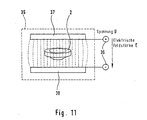
- a microwave system for heating the semi-finished products 2 is shown in FIG. 11.
- the system consists of a microwave active space 35, the coupling 36, the entry surface 37 and the exit surface 38.
- the heating takes place by converting the power loss proportional to the operating frequency and the square of the electric field strength. This principle allows short heating times and homogeneous heating.
- Fig. 1G also shows an arrangement of the Radiant heater 8 below the semi-finished product 3 with the semi-finished product 2. This Heating from below is a preferred option.
- the semi-finished product 2 with the carrier 3 must be by means of a Transfer stage ÜF can be stored in the cup forming unit BF, as in FIG. 1 is symbolically represented by an arrow. This transfer can be made by a Swivel arm rotating (vertical, horizontal) or translational. The skilled person has various options for this.
- the Semi-finished product carrier 3 with the semi-finished product 2 is on the swivel arm during the heating and transfer movement by a gripper captured.
- the cup forming unit BF in which the cup formation takes place by blowing, and which is shown in a somewhat enlarged form in FIG. 1A, is the heart of the manufacturing unit, since the semi-finished products 2 are cups on it 1 be formed by blowing.
- the actual shape corresponds to that current shaping process, which is characterized by blowing a rotating cup in a two-part, non-rotating form temporary cup support by a floor lifter. Basically can a rotating mold with a fixed parison can also be used.
- the blow mold 11 has a vertically divided, two-part mold jacket for the shape of the parison with two-part, attached blow mold, where the opening and closing of the mold is controlled automatically.
- This automatic Exchange is realized by an exchange unit WE according to FIG. 1 for several manufacturing units, as will be explained later.
- Pastes sawdust, etc. are used to prepare the blow mold or the mold is soaked with water to form a vapor cushion between glass and mold (release agent).
- the floor lifter 12 serves to improve the wall thickness distribution and Bottom quality of the cup, especially with heavy glass. It turns synchronously with the blowing unit 10 and has an automatically controlled opening and closing Movement for targeted soil support. For the production of twisted Glasses can also have the rotational frequency compared to that of Blow unit or the blow head have a phase offset that is adjustable is.
- the floor lifter also called floor plate, is equipped with a Device (gripper, suction head or similar) for receiving the cup 1 and is through a quick change system changeable.
- a Device gripper, suction head or similar
- the cooling nozzles have the function of an air and Water cooling to influence the rim thickness of the cup 1 by Cooling the parison and / or the form and protecting the form from Overheating.
- the cooling nozzles are optimal in position and throughput adjustable. The actuation is freely selectable via solenoid valves.
- FIG 1K shows an embodiment of the device in an enlarged view Blow head 9 and the blow unit 10, in which the semifinished product carrier 3 at the same time Working ring of blow molding forms.
- the rotation of this working ring which is rotatable via a bearing 14 on a support 10a of the blow unit 10 rests, is transmitted via the blow head.
- the corresponding 1H in addition to the compressed air, a laser beam for the variant according to FIG Plasticization of the semi-finished product 2 performed on the blowing station.
- the function module BF of the cup formation follows, as in FIG. 1 shown the cup removal BE. At this stage, the finished, on the Floor lifter 12 standing hollow glass 1 from a removal device 15 gripped and placed on a removal device 16.
- a modular, interchangeable and tailored to the respective article pneumatically operated gripper 17 lifts the cup 1 from the floor lifter 12. Through a combination of rotating and translational movement the cup led to the removal device 16. Whichever Manufacturing depth (with / without stem; with / without overglass) the respective hollow glass the removal is present, the hollow glass must be placed on the Removal device for storage on the over-glass or the edge of the mouth otherwise it will be discontinued without turning.
- An essential element of the present invention is the use of Semi-finished products 2 as the starting product in a separate production line be produced independently of the blow molding process.
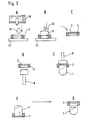
- a special meaning has the production of a shape-optimized semi-finished product 2 in one annular semi-finished product carrier 3, which is also the subject of the illustration in 1 is. 2 with the states A to G, the Manufacture of this special semifinished product, which the above mentioned has significant advantages and explains its diverse tasks become.
- the circular semi-finished product carrier 3 has the task that he Semi-finished product 2, as shown in stage C, picks up. For this the Semi-finished product carrier 3 in stage A, resting on a base 21, with glass 19 poured by drop feeding from a glass melt 18, the glass 19 according to state B by a press ram 20 in the carrier on the shape-optimized configuration is brought.
- the glass 2 is in the later glass forming process in the carrier 3 by means of Heat source 8 melted (state D) before being in the machine Blowing process with the die 9 is formed into a hollow glass 1 under Replacement of the previous work ring with the semi-finished product carrier (level E).
- the semifinished product carrier 3 can be simplified, serve safe transport of the hollow glass 1 until it is targeted by the hollow glass is separated.
- the semifinished product carrier 3 generally protects the glass blank, the semifinished product 2 Transport damage and simplified the storage of semi-finished products, in particular through their stackability.
- the tablet 2 can correspond to FIG. 3 (A. B) can be made in such a way that a mold 22 by Drop feeding of a glass drop 19 from a glass melt 18 is poured out, the glass drop 19, which is now in the form of a Has adopted a press die 20 in the form 22 to a lens flat disc is pressed.
- the tablet 2 can also by cutting out a flat glass 24 using a suitable tool 23 are manufactured.
- a suitable tool 23 it is also possible to use the flat one round glass pane 2 from a flat glass 24 by means of a suitable Cut out cutting tool 25.
- FIG. 4 shows another possibility for the production of semi-finished products shown.
- the semifinished product consists of a with respect to the hollow-glass molded body to be produced with a shape-optimized profiled tablet 2, which is analogous to the flat disc 2 according to that shown in FIG. 4A
- a shape-optimized profiled tablet 2 which is analogous to the flat disc 2 according to that shown in FIG. 4A
- This will be done accordingly designed form 22 by feeding a drop 19 from a drop Glass melt 18 poured out, the glass drop 19 by a Press die 20 in the form 22 brought to the shape-optimized configuration becomes.
- the basic procedure for the production of semi-finished products 2 Sintering of granular powder (quartz sand, other components) is used 4B with process steps 1-6 described in more detail.
- the exemplary embodiment is a shape-optimized tablet according to FIG. 4 as a semi-finished product 2 shown. It goes without saying that the semi-finished products also have a different shape can, e.g. 3 can be a disc. Sintering is one too Glass body in a semi-finished product carrier, which also forms the shape conceivable according to FIG. 2.
- the hollow glass recipe is composed of different raw materials, in 4B three substances 39 are indicated, which together form the mixture form.
- the main components are: glass melting sand, low iron lime, Potassium carbonate, sodium nitrate, soda heavy, barium carbonate.
- the Bulk density of the main ingredients is between 1-1.4 g / ml, the density up 2.7 g / l, the grain sizes are between 0.01 and 1.6 mm.
- the mixing is followed by a process step in which the mixture compressed and to the desired configuration of the semifinished product 2 Green body, is brought.
- the green density of the body after shaping depends on the used molding process between 10 and 45% of the density of the later sintered body, i.e. the green bodies shrink during sintering considerably.
- the drying of the wet green bodies belongs like in ceramics because of the Risk of cracking to the critical process steps. That is why in experiments in the past have been carried out through the glass particles Prepress directly without forming a dispersing liquid. But there uniform dispersion of the particles (homogeneous structure) without liquid It is very difficult to achieve in most known applications the shape of liquid-shaped green bodies. For this reason Various drying processes have been developed to match the Particle size, the green density and the resulting Pore diameters are adjusted.
- the dispersing liquid is water Diffusion against a liquid with a lower surface tension exchanged, which then in the further course of drying out of the pore spaces escapes.
- so-called supercritical drying can be used a complex process for drying without cracks and without shrinkage of the green body.
- the cleaning usually in a chlorine-containing atmosphere carried out does not only extend to contaminants Grain surfaces, but also due to impurities in the grain, due to the small diffusion paths can diffuse to the surface in a short time. There they react with the chlorine-containing atmosphere and get through it open pore system to the surface of the molded body.
- Step 5 sintering
- the still open-pore green body becomes one compacted transparent glass, which ideally has no pores.
- the temperature is increased so that the pores over a viscous flow getting closed.
- Sintering usually takes place in a conventional furnace, in which several heating elements heated by electric current (e.g. graphite, MoSi 2 , ZrO 2 ) generate heat, which is transferred to the molding via a working tube by means of heat conduction, convection and radiation.
- the blank is in the working tube.
- Most furnaces are operated with air as the furnace atmosphere, some furnaces (graphite) are also operated with an N 2 / H 2 inert gas atmosphere.
- radiation sintering is also known, a process that involves a cold working tube, in which the molding with a thermal Heater or a laser is heated.
- Heating by means of microwave plasma or using a plasma torch is provided.
- Step 6 control
- the sintered semi-finished product is checked extensively 2 on weight, volume, composition and condition.
- the stem connection with the Include chalice in the manufacturing process is not mandatory, as shown in Figure 5, the stem connection with the Include chalice in the manufacturing process.
- the vertical range of manufacture can also be designed so that a cup without a stem is manufactured in the production unit becomes, so to speak, as a semi-finished product that is only included in a later production process a stem is provided.
- Making the connection between stem 26 and chalice 1 immediately after the chalice formation in the functional unit KF has the advantage that the manufacturing process is streamlined and that after the Bubbles existing goblet heat, heat that when connecting anyway is needed, can be exploited.
- the goblet 1 with the stem 26 can, depending on the intended manufacturing depth, either with the so-called overglass or with separated overglass in the calyx removal KE are transferred.
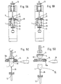
- a separation is shown in FIG. 5A of the over-glass 30 from the remaining cup 1 with the beam of a laser 29 shown, wherein in the schematic representations, according to Figures 5C and D, the processes taking place are clarified again.
- the laser beam from the laser 29 is passed through optics (not shown) to the chalice 1 brought up when the glass mold 11 is open after the molding process and the floor lifter 12 is in the upper position and the glass 1 together Holds handle 26 from below.
- the blow head 9, the cup 1 and the floor jack 12 rotate while the blow head 9 in the lower position is located, as shown in Figure 1K.
- the laser separation shown can optionally also be done before The goblet and stem are brought together. A is then removed Goblet without glass and stem.
- the functional module BE takes over the finished hollow glasses 1 and transfers them to the follow-up process.
- the hollow glasses 1 are in after the molding process the cup formation KF by the removal device 17 on the belt 16, the removal device, discontinued, as already in connection with the Figure 1 has been explained.
- the goblets are in the removal device 16 buffered and forwarded in a defined manner (individually or in a certain number), as will be explained later with reference to FIG. 9.
- the hollow glasses When the hollow glasses are removed, here in the form of the goblets, they have each according to selected options (with / without stem connection, with / without Glass separation) different manufacturing depths reached.
- the cup can be opened after the overglass has been separated its bottom plate standing, can be picked up on the conveyor belt 16.
- the annular semi-finished product carrier 3 is not yet to take off the hollow glass on the belt 16 with the semi-finished product carrier down, that is, goblet upside down. The separation of Semi-finished product carrier 3 and the chalice then take place in subsequent processes.
- There are other variants depending on how the stem and the goblet are removed are optionally merged.
- goblets and cups have been described. It understands other hollow glasses, such as beer glasses, Bottles or the like, with the inventive method or associated device can be molded.
- the entire production facility is preferably constructed in such a way that several modularly combinable production units (FE1, FE2 , FEn) one Section and several sections form a production facility.
- a such a production facility is shown in Figure 6, each Manufacturing unit with individual function modules, optionally optional.
- FIG. 7 shows a variant in which several manufacturing units can have common function modules, as by the corresponding Block formation is indicated.
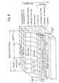
- FIG. 8 Such a completed production facility is shown in FIG. 8 shown.
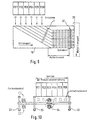
- FIG. 9 shows the removal of the hollow glasses 1 produced via the Conveyor belt 16 which is arranged transversely in front of one another Manufacturing facilities FE is located. Special bumpers prevent glasses already on the belt with new glasses collide.
- the glasses 1 are buffered so that they by a slider 31 which operates in a clocked manner, e.g. to a connecting strap 32 can be handed over.
- Figure 10 is the principle of automatic change of shape for the individual functional units.
- the blow molds 11 in the individual functional units are before their Paste paste so that the paste layer can absorb the water, which forms the separating vapor cushion during the blowing process.
- the molding process wears out the paste layer and the molds have to be removed during the ongoing production are gradually replaced.
- the unit for automatic mold change shown in Figure 10, in the Figures 1 and 5, the functional unit WE, enables the speedy Change of mold on a production unit without additional personnel expenditure, while production can continue on the neighboring units.
- the chalice can be monitored immediately after shaping Shape changes are initiated if there are defective chalices there.
- the automatic changing device is located across from each other arranged manufacturing facilities above the removal, as from the Figure 8 emerges.
- the respective production unit FE must be in the area the blow mold 11 be accessible from the removal side.
- the form coat, in from which the two inner mold halves are hung is wide open.
- On the portal 33 of the exchange unit is e.g. a rotatable, longitudinally movable two-sided gripper arm 34. From one side of the arm the used mold halves are removed, the arm is turned through 180 ° then two new mold halves are made from the second side used.
- the unusable forms are on one side of the portal arranged mold station automatically exchanged for new molds ready for the next change.
- the method according to the invention and the associated method have been described above Device described in which by using the to manufacturing semi-finished products an independence from that Melting furnace operation is achieved.
- the modular structure of the The production facility fulfills the demand for a high level Flexibility in production, so that even in connection with a Tub operation through the inventive concept significant technical, entrepreneurial and economic advantages arise.
Landscapes
- Chemical & Material Sciences (AREA)
- Engineering & Computer Science (AREA)
- Materials Engineering (AREA)
- Organic Chemistry (AREA)
- Manufacturing & Machinery (AREA)
- Dispersion Chemistry (AREA)
- Physics & Mathematics (AREA)
- Geometry (AREA)
- Re-Forming, After-Treatment, Cutting And Transporting Of Glass Products (AREA)
- Blow-Moulding Or Thermoforming Of Plastics Or The Like (AREA)
- Moulds For Moulding Plastics Or The Like (AREA)
Description
- Ungleichmäßiger Wannenbetrieb bzw. Wannenauslastung je nach Gewicht der Produkte.
- Bei Produktionswechsel (Umrüsten) der Produktionsmaschinen ist eine Anpassung der Wannenleistung notwendig, wodurch zusätzliche Ungleichmäßigkeiten im Schmelzprozeß auftreten.
- Da eine Wanne mehrere Produktionslinien speist, kann nur Klarglas in der Wanne erschmolzen werden, welches erst unmittelbar vor dem Einspeisen in die jeweilige Produktionsmaschine in einem aufwendigen, komplexen Prozeß eingefärbt werden kann.
- Die Produktwechselzeit ist mit abhängig von der Größe der Gewichtsdifferenz der aufeinanderfolgenden Produkte, da dadurch die Dauer des Überführens der Speiseeinrichtungen in den neuen stabilen Betriebszustand erheblich beeinflußt wird.
- Herstellen von massiven Glasrohlingen in Form von konfektionierten Halbzeugen in einer eigenen separaten Fertigungslinie,
- Lagern und Bevorraten der Halbzeuge,
- Zufuhr der Halbzeuge aus der Bevorratung an die Fertigungslinie für das Ausformen der Hohlgläser unter Vorwärmen der Halbzeuge,
- Bereitstellen der vorgewärmten Halbzeuge für eine weitere Erwärmung,
- Erhitzen des Halbzeuges auf Blastemperatur zu einem plastisch verformbaren massiven Glasposten durch eine weitere Erwärmung,
- Formblasen des plastifizierten Glaspostens zu dem Hohlglas in einer Blasform mit Unterstützung des geblasenen Hohlglas-Formkörpers durch einen Bodenheber,
- Entnahme des Hohlglases aus der Blasform und Übergabe an den Folgeprozeß.
- eine Stufe mit Lagerungs- und Transporteinrichtungen zum Bevorraten und Zuführen von zwischengelagerten massiven Glas-Halbzeugen für das zu formende Hohlglas, die zuvor in einer eigenen separaten Vorrichtung hergestellt sind,
- eine nachgeschaltete Vorwärmstufe mit Wärmeeinrichtungen zum Vorwärmen der massiven Halbzeuge,
- eine Stufe mit Transporteinrichtungen zum Bereitstellen der massiven Halbzeuge an einer Halbzeug-Erwärmstufe mit Wärmeeinrichtungen zum weiteren Erwärmen der Halbzeuge zumindest auf eine Temperatur nahe der Blastemperatur, und
- durch eine Übergabestufe mit Einrichtungen zum Ablegen der in der Halbzeug-Erwärmstufe weiter erwärmten massiven Halbzeuge in die Blasformstufe, wo sie als plastisch verformbare massive Glasposten für die Blasformung der Hohlgläser zur Verfügung stehen.
- Einfacher Fertigungsprozeß, einfacher Transport und einfache Bevorratung von Halbzeugen.
- Gute, einfache Handhabung der flachen Halbzeuge.
- Aufsplittung der Halbzeugherstellung örtlich getrennt in den Flachglas-Rohling und die eigentlichen Halbzeugherstellung.
- die technologisch aufwendige Halbzeugherstellung,
- der Glasverschnitt nach dem Ausschneiden oder Ausstanzen, der wieder rückgeschmolzen werden muß,
- die Zerstörungs- und Beschädigungsgefahr des Halbzeuges beim Transport.
- Einfacher Fertigungsprozeß (üblicher Wannenbetriebs-Glasschmelzprozeß), einfacher Transport und einfache Bevorratung von gegossenen Halbzeugen.
- Gute, einfache Handhabung und Bevorratung flacher Halbzeuge.
- Einfacher Fertigungsprozeß der formoptimierten, profilierten Tablette (üblicher Wannenbetrieb).
- Blasoptimierter Prozeß ist möglich.
- Zerstörungs- und Beschädigungsgefahr des Halbzeuges beim Transport.
- Schwierige Handhabung und Lagerung des profilierten Halbzeuges.
- Schutz des Halbzeuges vor Zerstörung und Beschädigung durch den umgebenden Halbzeugträger.
- Es ist ein blasoptimierter Prozeß möglich. Bei optimierter Innenkontur des ringförmigen Halbzeugträgers kann das verlorene Restglas um bis zu 50 % gemindert werden.
- Einfacher Fertigungsprozeß, einfache Transportautomatisierung und Stapelbarkeit des Halbzeuges.
- Einfache Handhabung bei Handlingsvorgängen durch standardisierte geometrische Gestalt des Halbzeugträgers.
- Nutzung des Ringes als Arbeitsring während des Blasprozesses.
- Ersatz für Überglas, dadurch weniger Glasvolumen im Umlauf.
- Die Bereitstellung des Halbzeugträgers.
- Die Notwendigkeit des Trennvorganges von Halbzeug und Halbzeugträger.
- Der Aufbereitungs- und Entsorgungsaufwand des Halbzeugträgers.
- Fig. 1
- eine schematische Darstellung des erfindungsgemäßen Produktionsablaufes bei der Herstellung eines Bechers als Hohlglas-Formkörper,
- Fig. 1A
- einen vergrößerten Ausschnitt aus Fig. 1 betreffend die Blasstation,
- Fig. 1B
- ein Lagern und Bevorraten der Halbzeuge einschließlich deren Zufuhr gemäß einer ersten Ausführung mittels eines Förderbandes,
- Fig. 1C
- eine zur Fig. 1B alternative Ausführung der Halbzeug-Bevorratung mit einem Schieber,
- Fig. 1D
- die Vorwärmung der Halbzeuge in einem Vorwärm-Durchlaufofen,
- Fig. 1E
- die Bereitstellung der vorgewärmten Halbzeuge für eine weitere Erwärmung mit einer Schieberanordnung über eine Rutsche,
- Fig. 1F
- alternativ die Halbzeug-Bereitstellung mit einem Greifsystem,
- Fig. 1G
- das Erwärmen des Halbzeuges auf Blastemperatur mit einer unterhalb des Halbzeuges angeordneten Strahlungsquelle,
- Fig. 1H
- die endgültige Erwärmung des Halbzeuges auf Blastemperatur innerhalb des Blaskopfes durch einen kombinierten Blaskopf Strahlen/Blasen,
- Fig. 1J
- die Erwärmung auf Blastemperatur parallel zum Blasprozeß,
- Fig. 1K
- eine Ausschnittsvergrößerung aus der Blasstation mit der bevorzugten Variante, bei der der Halbzeugträger auch den Blasring bildet,
- Fig. 2
- in verschiedenen Zuständen A bis G die Herstellung eines formoptimierten Halbzeuges durch Ausgießen eines Halbzeugträgers mit Glasrohstoff aus einer Schmelze, wobei das Halbzeug in den folgenden Schritten bis zum Abtrennen des geblasenen Hohlglas-Formkörpers in dem Halbzeugträger verbleibt,
- Fig. 3
- ein Halbzeug in Form einer flachen Tablette, die gemäß der Variante A durch Gießen in einer Form, gemäß der Variante B durch Ausstechen (Stanzen) aus einem Flachglas oder gemäß der Variante C durch Schneiden aus einem Flachglas hergestellt wird,
- Fig. 4
- eine formoptimierte profilierte Tablette als Halbzeug, die gemäß der Variante A durch Gießen in einer Form oder gemäß der Variante B durch Sintern hergestellt wird,
- Fig. 5
- eine schemtaische Darstellung des erfindungsgemäßen Produktionsablaufes bei der Herstellung von Kelchen mit Stiel,
- Fig. 5A
- eine Ausschnittvergrößerung der Blasstation der Fig. 5 unter Darstellung der Abtrennung des Überglases mit einem Laser,
- Fig. 5B
- ebenfalls eine Ausschnittsvergrößerung betreffend die Blasstation der Fig. 5 unter Darstellung der Verbindung des Stieles mit dem Kelch,
- Fig. 5C
- eine schematisierte Darstellung der Abtrennung des Überglases mittels eines Lasers,
- Fig. 5D
- in einer schematisierten Darstellung die Zustände in der Blasform nach Abtrennung des Überglases,
- Fig. 6
- den modularen Aufbau der erfindungsgemäßen Produktionseinrichtung gemäß einer ersten Alternative,
- Fig. 7
- den modularen Aufbau der erfindungsgemäßen Produktionseinrichtung gemäß einer zweiten Alternative,
- Fig. 8
- die Gesamtkonzeption der Produktionseinrichtung mit den Peripheriesystemen,
- Fig. 9
- den Abtransport der Hohlglas-Formkörper bei den modularen Produktionseinrichtungen gemäß den Fign. 6 und 7,
- Fig. 10
- eine schematisierte Darstellung für den automatischen Formenwechsel in den Produktionseinrichtungen nach den Fign. 6 und 7, und
- Fig. 11
- eine schematische Darstellung der Erwärmung eines Halbzeuges nach Fig. 4 mittels eines Mikrowellensystems.
- Halbzeugbereitstellung HB
- Halbzeugerwärmung HE
- Becherformung BF
- Becherentnahme BE
bilden das Grundgerüst einer Fertigungseinheit. Weitere Module können optional hinzugefügt werden, z.B. bei der noch zu erläuternden Kelchherstellung die Funktionsmodule:
- Stielpressen
- Verbindung Stiel und Kelch
- Abtrennen des Überglases.
- Erwärmung von ca. 500°C auf etwa 900°C kurz vor der Becherformeinheit BF, anschließend
- Übergabe an die Becherformeinheit
- die Form 11 offen
- der Arbeitsringträger der Blaseinheit 10 ebenfalls offen, und
- der Bodenheber 12 mit dem Becher 1 in der unteren Stellung, in der die Entnahme des Bechers 1 erfolgt.
- Zuführen Übersetzen vom Aufschmelzpunkt zur Blaseinheit
- Zentrieren Zentrierung in Blaseinheit, damit er beim Blasen rundumläuft
- Fixieren Sichern gegen Verdrehen beim Blasen
- Abdichten gegen Blaskopf damit Blasluft nicht entweicht
- Lösen vor seiner Entnahme
- Entnehmen des Halbzeugträgers inkl. anhängendem Becher, Wenden und Übergabe an Folgeprozeß.
- Der Halbzeugträger ist ringförmig.
- Der offene Ringkern wird mit dem Glas ausgegossen, das später durch Blasen zum Hohlglas geformt wird. Dabei muß er den Glasschmelztemperaturen von bis zu 1100°C standhalten (thermische Formstabilität).
- Das Profil der inneren Ringkontur ist optimal an den späteren Hohlglas-Formprozeß angepaßt.
- Die Ringaußenkontur ist in Form, Dicke und Durchmesser standardisiert, damit der Halbzeugträger in einheitlichen Blasstationen aufgenommen werden kann. Der Ring muß auf der Blasstation zentriert und fixiert werden, da sich die Station während dem Blasen mit bis zu 50 Umdrehungen/min dreht. Der Blaskopf liegt dabei während des Blasens auf dem Ring auf.
- Das Rohlingsgewicht und damit die spätere Hohlglasgröße wird variiert durch verschiedene Füllgrade des Ringes.
- Nach dem Abtrennen des Hohlglases vom Halbzeugträger verbleibt verfahrensbedingt ein geringer Rest im Ring. Vor einem erneuten Ausgießen des Ringes mit Glas muß dieser aufbereitet werden (Säubern, evtl. Pasten mit Trennmittel).
- Einsparung von Schmelzprozessen
- Kosteneinsparung
- einfachere Technologie.
- Trockene Mischung: Mischung der pulverförmigen Rohstoffe (Quarzsand, sonstige Bestandteile) im trockenen Zustand.
- Dispergierung der Pulverteilchen in einer Flüssigkeit: Bei der Lagerung der pulverförmigen Rohstoffe bilden sich Agglomerate, die bei der Dispergierung weitestgehend aufgelöst werden, um einen homogenen Grünkörper zu erhalten. Dadurch ist die erreichbare Homogenität höher als bei der trockenen Mischung. Als Dispergierflüssigkeit ist reines Wasser sehr geeignet.
- Gute Homogenität des Formkörpers. Sonst Gefahr unerwünschter Störstellen im gesinterten Glas.
- Gleichmäßige, möglichst enge Porenstruktur. Dadurch gleichmäßige Schrumpfung beim Sintern, konforme Abbildung der gewünschten Geometrie, geringere Sintertemperaturen bei engeren Poren.
- Geometrie entsprechend den Anforderungen. Zur Vermeidung einer aufwendigen Nachbearbeitung.
- Geringe Kontamination durch Störstoffe,
Unerwünschte Verunreinigungen, z.B. Alkali- und
Erdalkaliverunreinigungen, bilden Störstellen im Produkt und können
nur bei hohen Temperaturen beseitigt werden.Für die Formgebung eignen sich nachstehende Verfahren:
- A. Uniaxiales Pressen von Pulvern Darunter versteht man die Verdichtung des Pulvers mittels eines Preßstempels 40 von einer Seite aus.
- B. Isostatisches Pressen von Pulvern Darunter versteht man die Verdichtung von rieselfähigem Pulver mit ausreichend hoher Schüttdichte von mehreren Seiten, ggf. mit zusätzlicher thermischer Behandlung. Die notwendige Schüttdichte wird bei bestimmten Pulvern (z.B. Kieselsäuren) durch Voragglomeration erreicht.
- C. Strangpressen Dieses Verfahren sieht ein kontinuierliches Strangpressen einer glatten, plastischen Masse, zumeist Dispersion, vor.
- D. Zentrifugieren Dieses Verfahren beinhaltet das Abzentrifugieren der Teilchen aus einer dünnflüssigen Suspension.
- E. Kolloidale Filterung (Schlickerguß) Darunter versteht man die Phasentrennung der dispergierten Teilchen von der Dispergierflüssigkeit (Schlicker) durch Herauspressen der Flüssigkeit aus einer Form durch einen Filter, der die Teilchen zurückhält.
- F. Formgebung durch Vernetzung Dieses Verfahren bezieht sich auf eine Ausflockung (Koagulation) kolloidaler Teilchen einer dafür geeigneten Suspension. Die Eignung wird oft erst durch bestimmte Zusätze, meist Fluoride, erreicht. Die Suspension ist dann nur im stark gescherten Zustand dünnflüssig, während sie sich im Ruhezustand verfestigt (Thixotropie).
- G. Elektrophoretische Abscheidung Das Verfahren wird hier der Vollständigkeit halber genannt, da eine industrielle Anwendung derzeit nicht bekannt ist. Die Teilchen in einer homogenen Suspension bewegen sich beim Anlegen eines elektrischen Feldes gleichförmig auf ein Filter zu und bilden dort den Grünling.
- H. Sol-Gel Verfahren Mit dem Sol-Gel Verfahren können Gläser hergestellt werden, ohne daß ein Schmelz- oder Läuterungsprozeß notwendig ist. Der Aufbau des Glasnetzwerkes erfolgt durch Abscheidung von gelöstem SiO2 in einem Gel. Nach der Entwässerung kann das Gel zu einem kompakten Glas weit unterhalb der Schmelztemperatur gesintert werden.
- einfacher Fertigungsprozeß der formoptimierten, profilierten Tablette
- blasoptimierter Prozeß möglich.
- Halbzeug-Bereitstellung und Vereinzelung,
- Halbzeug-Kontrolle,
- Halbzeug-Vorwärmung,
- Halbzeug-Plastifizierung,
- Stielpressung. Der vollautomatische Preßtakt der Stielpresse SP ist dabei auf den Takt der Formgebung angepaßt. Die Halbzeuge werden dabei aus einem Lager entnommen und der Halbzeug-Bereitstellung zugeführt. Nach der Einzelkontrolle werden sie in einem Durchlaufofen vorgewärmt, anschließend auf einer weiteren Station unmittelbar vor dem Pressen plastifiziert. In einer zweigeteilten Stielpreßform werden sie von oben mit einem Druckstempel zu Stielen gepreßt, bevor die Preßform öffnet und der Stiel samt Bodenplatte mit einem geeigneten Übersetzer an die Funktionseinheit SZ übergeben wird. In dem Funktionsmodul SZ befindet sich ein Durchlauf-Vorwärmofen 28, dem die Stiele 26, entweder als Halbzeug aus einer nicht dargestellten Bevorratung oder von der Stielpresse SP her durch ein Zuführsystem, z.B. einem Greifer, zugeführt werden. Dort werden sie mit ihrer Bodenplatte, beispielsweise auf einem dargestellten Band stehend, durch den Ofen geführt und gezielt erwärmt. Kurz vor der Übergabe an den Bodenheber 12 durch einen geeigneten, ebenfalls nicht dargestellten Übersetzer mit Greifer, wird die Stielspitze, bevorzugt durch einen Strahler 27, nochmals gezielt erwärmt. Danach werden die Stiele, auf ihrer Bodenplatte stehend, an den Bodenheber 12 übergeben. Dort wird der Stiel 26 zentriert und gespannt. Der Bodenheber führt den heißen Stiel von unten an den Kelch 1 heran. Der für die Stielverbindung notwendige Druck wird über den Bodenheber 12 aufgebracht. Bei Bedarf kann die Verbindungsstelle während der Verbindung mit einem nicht dargestellten Strahler weiter erwärmt werden, während Kelch 1 und Stiel 26 gemeinsam drehen.Nach der erfolgten Verbindung wird das Stielglas 1 vom Bodenheber nach unten abgesenkt und von dem Entnahmegreifer 17 in den Funktionsmodul KE, die Kelchentnahme, übernommen.Die Figur 5B zeigt in einer vergrößerten Darstellung ausschnittsweise den Funktionsmodul KF, die Kelchformung mit der Anbringung des Stieles an den Kelch 1. Bei der dargestellten Position
- ist die Form 11 offen,
fährt der Bodenheber 12 mit dem Stiel 26 in die obere Stellung, - wird der Stiel 26 zentriert,
- wobei sich Kelch und Stiel drehen.
- Halbzeug-Bereitstellung,
- Halbzeug-Erwärmung,
- Hohlglasformung durch Blasen,
- Zusammenführen und Verbinden von als Halbzeug zur Verfügung gestellten Stielen mit einem Kelch (Option) oder
- Integration eines Stielfertigungsmoduls (Option) sowie
- Abtransport des fertigen Hohlglases
- Halbzeug-Bevorratung BV,
- Halbzeug-Kontrolle K,
- Halbzeug-Vorwärmung VW.
- Der gemeinsame Abtransport der Hohlgläser, vorzugsweise über das Förderband 16, und
- eine automatische Formwechseleinrichtung.
- Klarer Materialfluß innerhalb einer Fertigungseinheit von oben nach unten.
- Geringe spezifische Formenkosten,
- Möglichkeit der weiteren Verbesserung bestimmter Produkteigenschaften, z.B. Verminderung der Wandstärke, bessere geometrische Gestalt (Kappen- und Bodenglasplanität, Stielzentrizität, o.ä.).
- Vereinfachung der nachfolgenden Prozesse durch hohe erreichbare Fertigungstiefen (Wertschöpfung) auf der Produktionseinrichtung.
- Einfachere Fertigung farbiger Gläser und/oder Stiele.
- Gleichzeitige parallele Fertigung mehrere kleiner Losgrößen bzw. Fertigung einer ganzen Glasserie auf einer Einrichtung.
- Versuchsbetrieb auf einer Fertigungseinheit (Nullserien neuer Artikel, Test technischer Verbesserungen, o.ä.) parallel zur Produktion unter Produktionsbedingungen.
- Verbesserte Ausnutzung der räumlichen Situation am Produktionsstandort und Verminderung des Platzbedarfes durch variable Zusammenstellung (Anzahl, Aufbau etc.) mehrerer Produktionseinrichtungen.
- Betreiben der Produktionseinrichtung unabhängig vom technologie- und investitionsintensiven Wannenbetrieb.
- Fertigung kleiner Losgrößen mit geringem Formeneinsatz.
- Geringere Verluste bei Maschinenumrüstung durch schnelleren Umbau parallel zur Produktion.
- Geringere Ausfallzeiten (kein Stillstand der Gesamtanlage) bei Maschinenschäden durch zügigen Austausch des defekten Moduls oder der kompletten Fertigungseinheit gegen funktionstüchtige Baugruppen.
- Verminderung der Betriebskosten (Personal, Material, Energie, Formen) durch einen gestrafften Produktionsprozeß.
Claims (35)
- Verfahren zur Herstellung von Kelchgläsern, Bechern und gleichartigen Hohlgläsern (1) durch Blasformen eines geschmolzenen massiven Glaspostens, mit den Schritten:Herstellen von massiven Glasrohlingen in Form von konfektionierten Halbzeugen (2) in einer eigenen separaten Fertigungslinie,Lagern und Bevorraten der Halbzeuge (2),Zufuhr der Halbzeuge aus der Bevorratung an die Fertigungslinie für das Ausformen der Hohlgläser unter Vorwärmen der Halbzeuge,Bereitstellen der vorgewärmten Halbzeuge (2) für eine weitere Erwärmung,Erhitzen des Halbzeuges (2) auf Blastemperatur zu einem platisch verformbaren massiven Glasposten durch eine weitere Erwärmung,Formblasen des plastifizierten Glaspostens zu dem Hohglas in einer Blasform (10,11) mit Unterstützung des geblasenen Hohlglases durch einen Bodenheber (12),Entnahme des Hohlglases (1) aus der Blasform (10,11) und Übergabe an den Folgeprozeß.
- Verfahren nach Anspruch 1, gekennzeichnet durch eine indirekte Halbzeug-Herstellung durch Ausstechen oder Schneiden von runden flachen Glasscheiben (2) aus einem Flachglas (24) als Halbzeug für das Formblasen.
- Verfahren nach Anspruch 1, gekennzeichnet durch eine direkte Halbzeug-Herstellung durch Gießen einer Tablette (2) in einer Form (22) im Anschluß an das Aufschmelzen eines Glasrohstoffes als Halbzeug für das Formblasen.
- Verfahren nach Anspruch 3, gekennzeichnet durch das Gießen einer flachen Tablette (2).
- Verfahren nach Anspruch 3, gekennzeichnet durch das Gießen einer in bezug auf das herzustellende Hohlglas formoptimierten profilierten Tablette (2).
- Verfahren nach Anspruch 1, gekennzeichnet durch eine direkte Herstellung eines in bezug auf das herzustellende Hohlglas formoptimierten Halbzeuges (2) durch Ausgießen eines Halbzeugträgers (3) mit einer optimierten Innenform mit Glasrohstoff aus einer Schmelze, wobei das Halbzeug (2) in den folgenden Schritten bis zum Abtrennen des geblasenen Hohlglases in dem Halbzeugträger (3) verbleibt.
- Verfahren nach Anspruch 1, gekennzeichnet durch eine Herstellung des Halbzeuges (2) mit einer vorgegebenen Konfiguration durch einen Sinterprozeß.
- Verfahren nach Anspruch 7, dadurch gekennzeichnet, daß das Halbzeug (2) in einem Halbzeugträger (3) mit einer die Konfiguration vorgebenden Innenform gesintert wird, wobei das Halbzeug in den folgenden Schritten bis zum Abtrennen des geblasenen Hohlglasformlings in dem Halbzeugträger verbleibt.
- Verfahren nach Anspruch 7 oder 8, gekennzeichnet durch einen Sinterprozeß mit den Verfahrensschritten:Mischen der Rohstoffe (39)Formgeben eines GrünkörpersTrocknen des Grünkörpers, optional je nach dem FormgebungsverfahrenReinigen des GrünkörpersSintern des Grünkörpers zu dem Halbzeug (2) für die Herstellung des HohlglasesKontrolle des gesinterten Halbzeuges (2).
- Verfahren nach einem der Ansprüche 1 bis 9 zur Herstellung von Kelchen (1) mit einem Stiel (26), gekennzeichnet durch das Zusammenführen und Verbinden von extern als Halbzeug gefertigten Stielen (26) mit dem formgeblasenen Kelch (1) in der Blasform.
- Verfahren nach einem der Ansprüche 1 bis 9 zur Herstellung von Kelchen (1) mit einem Stiel (26), gekennzeichnet durch das Zusammenführen und Verbinden von innerhalb der Fertigungslinie gefertigten Stielen (26) mit den formgeblasenen Kelchen (1) in der Blasstation (KF).
- Verfahren nach einem der Ansprüche 1 bis 11, dadurch gekennzeichnet, daß das weitere Erhitzen des vorwiegend auf ca. 500°C vorgewärmten Halbzeuges (2) auf Blastemperatur von ca. 1050°C in zwei Stufen erfolgt, durch eine erste weitere Erwärmung auf ca. 900°C kurz vor der Blasstation (BF,KF) mit anschließender Übergabe des noch nicht plastischen Halbzeuges (2) an diese Station und durch eine zweite weitere Erwärmung des Halbzeuges auf Blastemperatur von ca. 1050°C in dieser Station (BF,KF).
- Verfahren nach einem der Ansprüche 1 bis 11, dadurch gekennzeichnet, daß das weitere Erhitzen des vorzugsweise auf ca. 500°C vorgewärmten Halbzeuges (2) auf Blastemperatur von ca. 1050°C in einem einzigen Schritt in einer gesonderten Vorrichtung (8) erfolgt mit Übergabe des plastifizierten Halbzeuges (2) an die Blasstation (BF,KF).
- Verfahren nach Anspruch 12 oder 13, dadurch gekennzeichnet, daß das weitere Erhitzen des Halbzeuges (2) mittels Mikrowellenstrahlung erfolgt.
- Verfahren nach einem der Ansprüche 1 bis 14, gekennzeichnet durch ein Abtrennen des Überglases (30) vom restlichen gewünschten Hohlglas (1) in der Blasstation (BF,KF) nach Öffnung der Form mittels eines Laserstrahles.
- Vorrichtung zur Herstellung von Kelchgläsern, Bechern und gleichartigen Hohlgläsern (1) mit einer Blasformstufe (BF, KF), bestehend aus einem Blaskopf (9) mit einem Blas-Arbeitsring, einer Blaseinheit (10), einer Form (11) und einem Bodenteller (12), in der ein geschmolzener Glasposten zu dem gewünschten Hohlglas formbar ist, und mit einer Entnahmestufe (BE, KE) enthaltend Einrichtungen (15, 17) zur Entnahme des Hohlglases (1) aus der Blasformstufe, sowie zur Übergabe an den Folgeprozeß, gekennzeichnet durch:eine Stufe (BV) mit Lagerungs- und Transporteinrichtungen zum Bevorraten und Zuführen von zwischengelagerten massiven Glas-Halbzeugen (2) für das zu formende Hohlglas (1), die zuvor in einer eigenen separaten Vorrichtung hergestellt sind,eine nachgeschaltete Vorwärmstufe (VW) mit Wärmeeinrichtungen (4, 4a) zum Vorwärmen der massiven Halbzeuge (2),eine Stufe (HB) mit Transporteinrichtungen (5, 5a, 6, 7) zum Bereitstellen der massiven Halbzeuge (2) an eine Halbzeug-Erwärmstufe (HE) mit Wärmeeinrichtungen (8) zum weiteren Erwärmen der Halbzeuge (2) zumindest auf eine Temperatur nahe der Blastemperatur, unddurch eine Übergabestufe (ÜE) mit Einrichtungen zum Ablegen der in der Halbzeug-Erwärmstufe (HE) weiter erwärmten massiven Halbzeuge (2) in die Blasformstufe (BF, KF), wo sie als plastisch verformbare massive Glasposten für die Blasformung der Hohlgläser zur Verfügung stehen.
- Vorrichtung nach Anspruch 16, dadurch gekennzeichnet, daß das Halbzeug (2) eine flache Tablette ist).
- Vorrichtung nach Anspruch 16, dadurch gekennzeichnet, daß das Halbzeug (2) eine formoptimierte Tablette ist.
- Vorrichtung nach Anspruch 16, dadurch gekennzeichnet, daß das Halbzeug (2) als formoptimierter Glaskörper in einem Halbzeugträger (3), mit diesem eine Verarbeitungseinheit bildend, aufgenommen ist.
- Vorrichtung nach Anspruch 19, dadurch gekennzeichnet, daß der Halbzeugträger ringförmig ist und daß in der Blaseinheit (11) der Blasformstufe (BF, KF) eine Aufnahme für den Halbzeugträger als Arbeitsring beim Formblasen vorgesehen ist.
- Vorrichtung nach Anspruch 19, dadurch gekennzeichnet, daß die Außenkontur des Halbzeugträgers (3) in Form, Dicke und Durchmeser standardisiert ist und das Profil der Innenkontur an das zu formende Hohlglas (1) angepaßt ist.
- Vorrichtung nach einem der Ansprüche 19 bis 21, gekennzeichnet durch eine Trenneinrichtung (29) zum Abtrennen des geformten Hohlglases (1) von dem Halbzeugträger (3).
- Vorrichtung nach einem der Ansprüche 16 bis 22, dadurch gekennzeichnet, daß zwischen der Bevorratungsstufe (BV) und der Vorwärmstufe (VW) eine Halbzeug-Kontrollstufe (KV) mit Einrichtungen zur Zustandskontrolle der Halbzeuge (2) eingeschaltet ist.
- Vorrichtung nach einem der Ansprüche 16 bis 23, dadurch gekennzeichnet, daß die Wärmeeinrichtungen (4, 4a) in der Vorwärmstufe (VW) durch einen Durchlauf-Wärmeofen (4) mit Strahlungsbrennern (4a) gebildet sind.
- Vorrichtung nach einem der Ansprüche 16 bis 24, dadurch gekennzeichnet, daß die Transporteinrichtungen in der Stufe (HB) zum Bereitstellen der Halbzeuge (2) durch Schieber (5, 5a) in Verbindung mit einer Rutsche (6) oder durch einen Greifarm (7) gebildet sind.
- Vorrichtung nach einem der Ansprüche 16 bis 25, dadurch gekennzeichnet, daß die Wärmeeinrichtungen in der Halbzeug-Erwärmstufe (HE) alternativ durch einen Wärmestrahler (8), einen Gas- oder Gas/Sauerstoffstrahler oder einen Mikrowellenstrahler (35-38) gebildet sind, die in einer weitgehend geschlossenen Kammer, vorzugsweise unterhalb der Halbwerkzeuge (2), angeordnet sind.
- Vorrichtung nach Anspruch 26, dadurch gekennzeichnet, daß die Wärmeeinrichtungen so ausgelegt sind, daß die Halbzeuge (2) auf eine Temperatur in der Nähe der Blastemperatur, vorzugsweise auf 900°C, erwärmt werden, mit Aufheizung auf die Blastemperatur in dem Blaskopf (9) der nachgeschalteten Blasformstufe (KF, BF) durch Einsatz eines Lasers mit Strahlzufuhr durch eine Bohrung im Blaskopf (9) für die Zufuhr der Druckluft.
- Vorrichtung nach Anspruch 26, dadurch gekennzeichnet, daß die Wärmeeinrichtungen so ausgelegt sind, daß die weitere Erwärmung auf Blastemperatur in einem einzigen Schritt in einer gesonderten Vorrichtung parallel zum Blasprozeß erfolgt.
- Vorrichtung nach einem der Ansprüche 16 bis 28, dadurch gekennzeichnet, daß die Einrichtungen in der Übergabestufe (ÜE) durch einen Schwenkarm mit Greifer gebildet sind.
- Vorrichtung nach einem der Ansprüche 16 bis 29, dadurch gekennzeichnet, daß die Stufen der Halbzeugbereitstellung (HB), der Halbzeugerwärmung (HE), der Blasformung (BF, KF) und der Entnahme (BE; KE) als eigenständige Funktionsmodule ausgebildet sind und das Grundgerüst einer modular aufgebauten Fertigungseinheit (FE) bilden, dem weitere Module, wie Stielzuführung, Stielpressen, Abtrennen von Überglas, optional hinzufügbar sind.
- Vorrichtung nach Anspruch 30, dadurch gekennzeichnet, daß mehrere Fertigungseinheiten (FE) modular zu einer Sektion kombiniert sind und mehrere Sektionen zu einer Produktionseinrichtung zusammengeschaltet sind.
- Vorrichtung nach Anspruch 31, dadurch gekennzeichnet, daß jede Fertigungseinheit (FE) mit einzelnen Funktionsmodulen bestückt ist.
- Vorrichtung nach Anspruch 31, dadurch gekennzeichnet, daß mehrere Fertigungseinheiten (FE) gemeinsame Funktionsmodule aufweisen.
- Vorrichtung nach einem der Ansprüche 31 bis 33, dadurch gekennzeichnet, daß hinter den Fertigungseinheiten (FE) die Stufen der Halbzeug-Bevorratung (BV), der Halbzeug-Kontrolle (K) und der Halbzeug-Vorwärmung (VW) angeordnet sind.
- Vorrichtung nach einem der Ansprüche 31 bis 34, dadurch gekennzeichnet, daß quer vor den Fertigungseinheiten (FE) und längs zur Produktionseinrichtung eine Abtransporteinrichtung (16) für den gemeinsamen Abtransport der hergestellten Hohlglas-Formkörper (1) und eine automatische Formenwechseleinrichtung (33, 34) vorgesehen ist.
Applications Claiming Priority (3)
| Application Number | Priority Date | Filing Date | Title |
|---|---|---|---|
| DE19722921 | 1997-05-31 | ||
| DE19722921A DE19722921A1 (de) | 1997-05-31 | 1997-05-31 | Verfahren zur Herstellung von Hohlglas-Formkörpern und zugehörige Vorrichtung zur Durchführung des Verfahrens |
| PCT/EP1998/002931 WO1998054102A1 (de) | 1997-05-31 | 1998-05-19 | Verfahren zur herstellung von kelchgläsern, bechern und gleichartigen hohlgläsern und zugehörige vorrichtung zur durchführung des verfahrens |
Publications (2)
| Publication Number | Publication Date |
|---|---|
| EP0991599A1 EP0991599A1 (de) | 2000-04-12 |
| EP0991599B1 true EP0991599B1 (de) | 2001-08-08 |
Family
ID=7831088
Family Applications (1)
| Application Number | Title | Priority Date | Filing Date |
|---|---|---|---|
| EP98930704A Expired - Lifetime EP0991599B1 (de) | 1997-05-31 | 1998-05-19 | Verfahren zur herstellung von kelchgläsern, bechern und gleichartigen hohlgläsern und zugehörige vorrichtung zur durchführung des verfahrens |
Country Status (10)
| Country | Link |
|---|---|
| US (1) | US6497119B1 (de) |
| EP (1) | EP0991599B1 (de) |
| CZ (1) | CZ298807B6 (de) |
| DE (2) | DE19722921A1 (de) |
| ES (1) | ES2167909T3 (de) |
| PL (1) | PL187055B1 (de) |
| PT (1) | PT991599E (de) |
| SK (1) | SK284304B6 (de) |
| TR (1) | TR199902930T2 (de) |
| WO (1) | WO1998054102A1 (de) |
Families Citing this family (17)
| Publication number | Priority date | Publication date | Assignee | Title |
|---|---|---|---|---|
| IT1320637B1 (it) * | 2000-09-12 | 2003-12-10 | Bottero Spa | Supervisore per una linea per la fabbricazione di articoli di vetrocavo. |
| DE10045373B4 (de) * | 2000-09-14 | 2007-02-01 | Schott Ag | Verfahren und Vorrichtung zum Erwärmen von Glas-Halbzeugen über die Klebetemperatur |
| DE10048057B4 (de) * | 2000-09-28 | 2007-03-29 | Schott Ag | Verfahren und Vorrichtung zur Bereitstellung wiedererwärmter Glasposten aus einem Halbzeug |
| DE10133640B4 (de) * | 2001-07-11 | 2005-05-25 | Schott Ag | Vorrichtung zum Transportieren von heißen verformten Glas- oder Glaskeramikteilen während ihrer Wärmebehandlung |
| SK3612004A3 (sk) * | 2004-09-21 | 2006-04-06 | J�N Granzer | Spôsob výroby banky stopkových sklenených nádob a zariadenie na vykonávanie tohto spôsobu |
| DE102004051329B4 (de) * | 2004-10-21 | 2008-07-31 | Schott Ag | Verfahren zur Herstellung von Hohlglaskörpern aus Borosilicatglas, Hohlglaskörper verformt nach diesem Verfahren und Verwendung dieses Hohlglaskörpers |
| DE102005061833B4 (de) * | 2005-12-23 | 2010-03-18 | Zwiesel Kristallglas Aktiengesellschaft | Vorrichtung und Verfahren zum Abtrennen einer Blaskappe |
| US7811084B2 (en) * | 2008-01-25 | 2010-10-12 | Fu-Chuan Huang | Steam shrink oven |
| CN103833199A (zh) * | 2012-11-24 | 2014-06-04 | 新余市银龙机电科技有限公司 | 一种触摸屏保护玻璃基片的生产工艺 |
| JP6385662B2 (ja) * | 2012-12-28 | 2018-09-05 | 日本電気硝子株式会社 | ガラス材の製造方法 |
| CN106915622A (zh) * | 2015-12-25 | 2017-07-04 | 李梦翔 | 一种玻璃瓶生产装置 |
| CN108249741B (zh) * | 2018-03-16 | 2023-11-10 | 济南晶焱自动化科技有限公司 | 全自动玻璃制品吹胎机及吹胎方法 |
| CN108423973B (zh) * | 2018-05-15 | 2023-11-03 | 嘉兴敏捷技术服务有限公司 | 自动玻璃器皿成型机上料同步加热机构 |
| CN108395077B (zh) * | 2018-05-15 | 2023-11-03 | 嘉兴敏捷技术服务有限公司 | 自动玻璃器皿成型机 |
| CN110482848B (zh) * | 2019-09-27 | 2024-01-12 | 济南晶焱自动化科技有限公司 | 全自动玻璃封底吹胎一体机及其吹胎方法 |
| EP4390888B1 (de) * | 2022-12-23 | 2025-01-29 | Bucher Automation Tettnang GmbH | Verfahren zur branderkennung bei produktionsmaschinen und produktionsmaschine |
| US12528729B2 (en) | 2023-06-08 | 2026-01-20 | Owens-Brockway Glass Container Inc. | Low-temperature glass container blowing process |
Family Cites Families (18)
| Publication number | Priority date | Publication date | Assignee | Title |
|---|---|---|---|---|
| US2254992A (en) * | 1937-11-30 | 1941-09-02 | Lynch Corp | Machine for and method of forming hollow glassware |
| NL108644C (de) * | 1959-05-22 | |||
| DE1224886B (de) | 1962-02-15 | 1966-09-15 | Philips Nv | Verfahren und Vorrichtung zur Herstellung von Glaskolben mit linsenfoermigem Boden |
| US3293017A (en) * | 1963-03-20 | 1966-12-20 | Corning Glass Works | Method for forming glass wafers |
| US3271126A (en) * | 1963-03-20 | 1966-09-06 | Corning Glass Works | Press forming apparatus for forming wafers from drips of glass |
| US3705026A (en) * | 1970-10-15 | 1972-12-05 | Bartlett Collins Co | Glassware dimpling |
| GB1346582A (en) * | 1971-08-27 | 1974-02-13 | Jobling & Co James A | Methods of and apparatus for producing glass or like thermoplastic columns and other articles |
| FR2383005A1 (fr) * | 1977-03-09 | 1978-10-06 | Solvay | Procede pour la production de corps creux en matiere thermoplastique et appareillage pour sa realisation |
| JPS6045132B2 (ja) * | 1979-03-05 | 1985-10-08 | 日本電気硝子株式会社 | 中空ガラス物品の吹成装置 |
| DE3239517A1 (de) * | 1982-10-26 | 1984-04-26 | Emil 8372 Zwiesel Ilk | Verfahren zur herstellung von kelchartigen glasgegenstaenden und vorrichtung zur durchfuehrung dieses verfahrens |
| DE3837372A1 (de) * | 1988-11-03 | 1990-05-10 | Vladimirskij Politekhn I | Anlage zum maschinellen formen von hohlerzeugnissen aus ueberfangglas mit einer farbschicht |
| JP2790547B2 (ja) * | 1991-03-28 | 1998-08-27 | 松下電器産業株式会社 | ガラス素材製造方法 |
| EP0535388A1 (de) * | 1991-09-03 | 1993-04-07 | Konica Corporation | Vorform und optischer Glaskörper und Verfahren zu ihrer Herstellung |
| DE69220902T2 (de) * | 1991-12-09 | 1998-02-12 | Philips Electronics Nv | Verfahren zum Pressen von Produkten sowie Vorrichtung zum Durchführen des Verfahrens |
| JP3164404B2 (ja) * | 1992-02-21 | 2001-05-08 | オリンパス光学工業株式会社 | ガラス光学素子の成形装置と成形方法 |
| JP3273197B2 (ja) * | 1992-07-03 | 2002-04-08 | 東芝機械株式会社 | 光学ガラス素子等の成形装置 |
| JPH06122525A (ja) * | 1992-10-13 | 1994-05-06 | Matsushita Electric Ind Co Ltd | 光学素子の成形装置及び成形方法並びに光学素子 |
| DE19521117A1 (de) * | 1995-06-09 | 1996-12-12 | Christian Klepsch | Verfahren und Vorrichtung zur Verformung von industriell hergestellten Glaskörpern |
-
1997
- 1997-05-31 DE DE19722921A patent/DE19722921A1/de not_active Withdrawn
-
1998
- 1998-05-19 ES ES98930704T patent/ES2167909T3/es not_active Expired - Lifetime
- 1998-05-19 SK SK1589-99A patent/SK284304B6/sk not_active IP Right Cessation
- 1998-05-19 DE DE59801188T patent/DE59801188D1/de not_active Expired - Lifetime
- 1998-05-19 PT PT98930704T patent/PT991599E/pt unknown
- 1998-05-19 WO PCT/EP1998/002931 patent/WO1998054102A1/de not_active Ceased
- 1998-05-19 PL PL98337032A patent/PL187055B1/pl unknown
- 1998-05-19 EP EP98930704A patent/EP0991599B1/de not_active Expired - Lifetime
- 1998-05-19 CZ CZ0391399A patent/CZ298807B6/cs not_active IP Right Cessation
- 1998-05-19 TR TR1999/02930T patent/TR199902930T2/xx unknown
- 1998-05-29 US US09/424,731 patent/US6497119B1/en not_active Expired - Lifetime
Also Published As
| Publication number | Publication date |
|---|---|
| CZ391399A3 (cs) | 2000-08-16 |
| PL187055B1 (pl) | 2004-05-31 |
| ES2167909T3 (es) | 2002-05-16 |
| US6497119B1 (en) | 2002-12-24 |
| TR199902930T2 (xx) | 2000-05-22 |
| SK284304B6 (sk) | 2005-01-03 |
| DE19722921A1 (de) | 1998-12-03 |
| WO1998054102A1 (de) | 1998-12-03 |
| PL337032A1 (en) | 2000-07-31 |
| CZ298807B6 (cs) | 2008-02-06 |
| SK158999A3 (en) | 2000-12-11 |
| PT991599E (pt) | 2002-01-30 |
| DE59801188D1 (de) | 2001-09-13 |
| EP0991599A1 (de) | 2000-04-12 |
Similar Documents
| Publication | Publication Date | Title |
|---|---|---|
| DE19722921A1 (de) | Verfahren zur Herstellung von Hohlglas-Formkörpern und zugehörige Vorrichtung zur Durchführung des Verfahrens | |
| EP1986967B1 (de) | Verfahren zur herstellung technischer glasteile für optische anwendungen | |
| EP2414151B1 (de) | Transportcontainer | |
| DE112012005570B4 (de) | Formvorrichtung und Formverfahren für Glasgehäuse | |
| DE3802544A1 (de) | Verfahren und vorrichtung zum herstellen von mehrschichtigen glasgegenstaenden | |
| WO2013131720A1 (de) | Formwerkzeug, verfahren und vorrichtung zur lasergestützten glasformung | |
| EP0804982A2 (de) | Verfahren zur Herstellung von Formteilen aus Metallschaum | |
| WO1998028122A1 (de) | Verfahren und vorrichtung zur übergabe von formlingen | |
| EP3275846B1 (de) | Verfahren zur lasergestützten umformung von glaskörpern | |
| DE2410923A1 (de) | Verfahren und vorrichtungen zum formen von glas in eine gewuenschte gestalt | |
| EP3299345A1 (de) | Verfahren zur herstellung eines optischen rohlings aus synthetischem quarzglas | |
| DE19510195C2 (de) | Verfahren zum Herstellen blankgepreßter Glaskörper für optische Ausrüstungen und Vorrichtung zur Durchführung des Verfahrens | |
| US10710918B1 (en) | Method of manufacturing a hollow glass article having a container shape | |
| DE68905703T2 (de) | Vorrichtung zum biegen von glasscheiben. | |
| DE2807447C3 (de) | Verfahren zur Herstellung von Hohlgläsern in einer IS-Glasformmaschine | |
| WO2023006298A1 (de) | Verfahren zum formen eines glasgegenstands, insbesondere eines dreidimensional geformten flachglasgegenstands, sowie vorrichtung zur durchführung des verfahrens und verwendung einer metallschmelze zur durchführung des verfahrens | |
| EP3722026A1 (de) | Vorrichtung und verfahren zur herstellung von dreidimensionalen bauteilen aus metallpulver | |
| EP1565410B1 (de) | Anlage zur herstellung von glasstopfen zum verschluss von flaschen | |
| EP1423341B1 (de) | Verfahren und fertigformstation zum fertigblasen eines glasbehälters | |
| DE69502441T2 (de) | Verfahren zur Herstellung von Komponenten aus Quarzglas und Pressform dafür | |
| DE10140626A1 (de) | Pressgeformter Glaskörper und Verfahren zu seiner Herstellung | |
| DE69228202T2 (de) | Verfahren zur Herstellung von Glasrohlingen | |
| EP1399390B1 (de) | Verfahren zum herstellen von reflektoren oder linsen | |
| DE60109517T2 (de) | Transfertrad zum Verfahren und Vorrichtung zum Herstellen von Gegenständen aus thermoplastischen Materialen | |
| EP1306177B1 (de) | Pressenanordnung, insbesondere zum Pressen von keramischen Presslingen |
Legal Events
| Date | Code | Title | Description |
|---|---|---|---|
| PUAI | Public reference made under article 153(3) epc to a published international application that has entered the european phase |
Free format text: ORIGINAL CODE: 0009012 |
|
| 17P | Request for examination filed |
Effective date: 19990917 |
|
| AK | Designated contracting states |
Kind code of ref document: A1 Designated state(s): DE ES FR IT PT |
|
| RBV | Designated contracting states (corrected) |
Designated state(s): DE ES FR IT PT |
|
| GRAG | Despatch of communication of intention to grant |
Free format text: ORIGINAL CODE: EPIDOS AGRA |
|
| GRAG | Despatch of communication of intention to grant |
Free format text: ORIGINAL CODE: EPIDOS AGRA |
|
| GRAH | Despatch of communication of intention to grant a patent |
Free format text: ORIGINAL CODE: EPIDOS IGRA |
|
| 17Q | First examination report despatched |
Effective date: 20010108 |
|
| GRAH | Despatch of communication of intention to grant a patent |
Free format text: ORIGINAL CODE: EPIDOS IGRA |
|
| GRAA | (expected) grant |
Free format text: ORIGINAL CODE: 0009210 |
|
| AK | Designated contracting states |
Kind code of ref document: B1 Designated state(s): DE ES FR IT PT |
|
| REF | Corresponds to: |
Ref document number: 59801188 Country of ref document: DE Date of ref document: 20010913 |
|
| ET | Fr: translation filed | ||
| REG | Reference to a national code |
Ref country code: PT Ref legal event code: SC4A Free format text: AVAILABILITY OF NATIONAL TRANSLATION Effective date: 20011029 |
|
| REG | Reference to a national code |
Ref country code: ES Ref legal event code: FG2A Ref document number: 2167909 Country of ref document: ES Kind code of ref document: T3 |
|
| PLBE | No opposition filed within time limit |
Free format text: ORIGINAL CODE: 0009261 |
|
| STAA | Information on the status of an ep patent application or granted ep patent |
Free format text: STATUS: NO OPPOSITION FILED WITHIN TIME LIMIT |
|
| REG | Reference to a national code |
Ref country code: ES Ref legal event code: PC2A |
|
| 26N | No opposition filed | ||
| REG | Reference to a national code |
Ref country code: ES Ref legal event code: PC2A |
|
| REG | Reference to a national code |
Ref country code: PT Ref legal event code: PD4A Owner name: ZWIESEL KRISTALLGLAS AKTIENGESELLSCHAFT, DE Effective date: 20050607 |
|
| REG | Reference to a national code |
Ref country code: ES Ref legal event code: PC2A |
|
| REG | Reference to a national code |
Ref country code: FR Ref legal event code: CD |
|
| REG | Reference to a national code |
Ref country code: FR Ref legal event code: PLFP Year of fee payment: 18 |
|
| REG | Reference to a national code |
Ref country code: FR Ref legal event code: PLFP Year of fee payment: 19 |
|
| PGFP | Annual fee paid to national office [announced via postgrant information from national office to epo] |
Ref country code: DE Payment date: 20160520 Year of fee payment: 19 Ref country code: ES Payment date: 20160512 Year of fee payment: 19 |
|
| PGFP | Annual fee paid to national office [announced via postgrant information from national office to epo] |
Ref country code: PT Payment date: 20160518 Year of fee payment: 19 Ref country code: FR Payment date: 20160520 Year of fee payment: 19 Ref country code: IT Payment date: 20160524 Year of fee payment: 19 |
|
| REG | Reference to a national code |
Ref country code: DE Ref legal event code: R119 Ref document number: 59801188 Country of ref document: DE |
|
| PG25 | Lapsed in a contracting state [announced via postgrant information from national office to epo] |
Ref country code: PT Free format text: LAPSE BECAUSE OF NON-PAYMENT OF DUE FEES Effective date: 20171120 |
|
| REG | Reference to a national code |
Ref country code: FR Ref legal event code: ST Effective date: 20180131 |
|
| PG25 | Lapsed in a contracting state [announced via postgrant information from national office to epo] |
Ref country code: DE Free format text: LAPSE BECAUSE OF NON-PAYMENT OF DUE FEES Effective date: 20171201 |
|
| PG25 | Lapsed in a contracting state [announced via postgrant information from national office to epo] |
Ref country code: FR Free format text: LAPSE BECAUSE OF NON-PAYMENT OF DUE FEES Effective date: 20170531 Ref country code: IT Free format text: LAPSE BECAUSE OF NON-PAYMENT OF DUE FEES Effective date: 20170519 |
|
| REG | Reference to a national code |
Ref country code: ES Ref legal event code: FD2A Effective date: 20180622 |
|
| PG25 | Lapsed in a contracting state [announced via postgrant information from national office to epo] |
Ref country code: PT Free format text: LAPSE BECAUSE OF EXPIRATION OF PROTECTION Effective date: 20180530 Ref country code: ES Free format text: LAPSE BECAUSE OF NON-PAYMENT OF DUE FEES Effective date: 20170520 |