EP0985530B2 - Dispositif d'encrage comprenant un rouleau tocheur-encreur pour la réduction de l'encre moutonnant - Google Patents
Dispositif d'encrage comprenant un rouleau tocheur-encreur pour la réduction de l'encre moutonnant Download PDFInfo
- Publication number
- EP0985530B2 EP0985530B2 EP99114183A EP99114183A EP0985530B2 EP 0985530 B2 EP0985530 B2 EP 0985530B2 EP 99114183 A EP99114183 A EP 99114183A EP 99114183 A EP99114183 A EP 99114183A EP 0985530 B2 EP0985530 B2 EP 0985530B2
- Authority
- EP
- European Patent Office
- Prior art keywords
- ink
- inking
- shore
- roller
- plate cylinder
- Prior art date
- Legal status (The legal status is an assumption and is not a legal conclusion. Google has not performed a legal analysis and makes no representation as to the accuracy of the status listed.)
- Expired - Lifetime
Links
- 238000007639 printing Methods 0.000 claims description 15
- 229920001971 elastomer Polymers 0.000 claims description 8
- 238000007645 offset printing Methods 0.000 claims description 7
- 230000004323 axial length Effects 0.000 claims description 4
- 238000011144 upstream manufacturing Methods 0.000 claims 2
- 239000013536 elastomeric material Substances 0.000 claims 1
- 239000000976 ink Substances 0.000 description 36
- 239000000806 elastomer Substances 0.000 description 6
- 239000000463 material Substances 0.000 description 6
- 239000007787 solid Substances 0.000 description 5
- 230000003287 optical effect Effects 0.000 description 4
- 230000000694 effects Effects 0.000 description 3
- 239000011324 bead Substances 0.000 description 2
- 238000010073 coating (rubber) Methods 0.000 description 2
- 238000001816 cooling Methods 0.000 description 2
- RYGMFSIKBFXOCR-UHFFFAOYSA-N Copper Chemical compound [Cu] RYGMFSIKBFXOCR-UHFFFAOYSA-N 0.000 description 1
- 206010061218 Inflammation Diseases 0.000 description 1
- 229910000831 Steel Inorganic materials 0.000 description 1
- 150000001875 compounds Chemical class 0.000 description 1
- 238000005094 computer simulation Methods 0.000 description 1
- 239000002826 coolant Substances 0.000 description 1
- 239000000110 cooling liquid Substances 0.000 description 1
- 230000001419 dependent effect Effects 0.000 description 1
- 230000008021 deposition Effects 0.000 description 1
- 238000006073 displacement reaction Methods 0.000 description 1
- 230000004054 inflammatory process Effects 0.000 description 1
- 238000013021 overheating Methods 0.000 description 1
- 238000005096 rolling process Methods 0.000 description 1
- 238000000926 separation method Methods 0.000 description 1
- 239000010959 steel Substances 0.000 description 1
- 238000009827 uniform distribution Methods 0.000 description 1
- 238000009736 wetting Methods 0.000 description 1
Images

Classifications
-
- B—PERFORMING OPERATIONS; TRANSPORTING
- B41—PRINTING; LINING MACHINES; TYPEWRITERS; STAMPS
- B41F—PRINTING MACHINES OR PRESSES
- B41F31/00—Inking arrangements or devices
- B41F31/26—Construction of inking rollers
Definitions
- the present invention relates to an inking unit in a rotary offset printing machine with an inking roller according to the preamble of claim 1, by means of which the beads of the solids contained in printing inks is reduced.
- Prior art offset printing machines comprise a plate cylinder having on its surface the image to be printed. This is in rolling contact with a transfer or blanket cylinder, by means of which the image contained on the plate cylinder is transferred to the web or the sheet.
- the plate cylinder is supplied with ink, which is then transferred to the blanket cylinder and then to the web / sheet.
- ink supply to the plate cylinder can be accomplished in a variety of ways, most commonly using a color box, i. H. a device in which a ink fountain roller on a container containing ink, the ink fountain, is arranged.
- a series of ink fountain keys At the interface between the ink fountain floor and the ink fountain roller are a series of ink fountain keys that can be moved toward and away from the ink fountain roller.
- the spacing of a respective ink fountain key from the ink fountain roller surface determines the thickness of the ink transferred to the outer surface of the ink fountain roller.
- a metering roller is arranged downstream of the ink fountain key in the direction of rotation.
- the metering roller leads from one or more rollers, for.
- the ink is transferred to the plate cylinder via the inking roller.
- inking rollers have an elastic, relatively soft outer surface made of an elastomer whose hardness is in the range between 22 and 28 Shore A (durometer).
- the outer surface is also cylindrical and has a uniform outer diameter.
- an offset printing unit which comprises a blanket cylinder, a plate cylinder, and an inking cylinder having a compliant working surface.
- a layer of an elastic, ink-accepting material is applied on the inking cylinder. The hardness of this layer is 60 to 70 Shore.
- an inking roller is known that is designed to reduce the risk of inflammation or loss of ink.
- a rubber coating is applied along a central region of the cylinder, wherein no rubber coating is provided at the end regions of the cylinder.
- a drawback encountered in offset printing machines of the prior art is that the solids contained in the ink bead. This results in an uneven ink application to the paper surface, creating a spotty image along the image surface of varying optical density. To compensate for this effect, it has often been necessary in the prior art to increase the amount of ink transferred to the paper.
- the present invention relates to a device which reduces the beading of the solids contained in printing inks. In this way, the print quality of a printing press is significantly improved by the present invention by a uniform distribution of the color solids is achieved on the entire print image. Furthermore, the present invention achieves a uniform optical density of the printed image with less ink consumption.
- one or more rollers whose outer surface consists of an elastomer having a hardness between 60 and 90 Shore A (durometer) or between 50 and 100 Shore A (durometer) are used as the inking rollers.
- the use of such an inking roller ensures a more uniform application of ink to the plate cylinder and thus to the blanket cylinder and the web to be printed.
- at least the inking roller, which contacts the plate cylinder in the direction of rotation last, is formed as an inking roller with a hard outer surface made of an elastomer.
- Significantly improved printing results can be achieved, however, if all the inking rollers are designed in this way.
- the inking roller has a convex shape axially along its length so that the diameter of the hard surface of an elastomer in the axial center is greater than at the axial ends, whereby an optimum contact between the Ink rollers and the plate cylinder is guaranteed.
- the present invention further relates to a printing machine, with the low ink consumption high print quality and a uniform optical density can be achieved because the ink is applied evenly to the plate cylinder by the inking rollers according to the invention and thus less color must be applied to achieve a certain print quality , Accordingly, the present invention provides an improvement over prior art printing machines in which significantly more color must be used to achieve a given print quality.
- Fig. 1 shows a schematic representation of a printing press according to the present invention.
- a material web W, z. B. of paper moves in a manner in the direction of the arrow between a rotating in the direction of arrow upper blanket cylinder B U and a rotating in the direction of arrow lower blanket cylinder B L through that it contacts the two cylinders.
- On the blanket cylinder B U and B L can each be applied a blanket 12.
- the plate cylinder and the inking unit by means of which the colored image is transferred to the upper blanket cylinder B U , are not shown.
- These components are the same or similar to the lower blanket cylinder B L associated components.
- the inking rollers F 1 , F 2 , F 3 can be fed by any known inking color; in Fig. 1 an inking roller 1 is shown, through which the ink is transferred to the plate cylinder P, which then transmits a colored image on the lower blanket cylinder B L.
- a rotating ink fountain roller I adjoins an ink fountain 10 and takes from this in a known manner to a color layer, which then transfers them to a metering roll M.
- the metering roller M By the metering roller M, the ink layer on a series of transfer rollers D and then on the distributor rollers V, a (vibrating) intermediate roller S and a large transfer roller L is transferred.
- the ink is transferred to one or more inking rollers F 1 , F 2 , F 3 .
- the inking rollers F 1 , F 2 , F 3 transfer a color layer on the plate cylinder P, but not necessarily three inking rollers must be provided, but the number of inking rollers can be chosen arbitrarily.
- the printing machine according to the present invention may comprise a downstream in the direction of rotation of the plate cylinder the blanket cylinder B L dampening unit 2, which can be used for wetting the plate cylinder P.
- a pressure plate 11 is arranged in a known manner, which transmits a colored image on the lower blanket cylinder B L , with which this then the web W imprinted.
- the inking rollers F 1 , F 2 , F 3 are used to control the thickness and the type of ink layer to be transferred to the plate cylinder P and accordingly the quality of the color printed image on the web W.
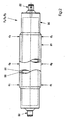
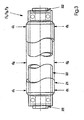
- Fig. 2 and 3 show two embodiments of an inking roller F 1 , F 2 or F 3 according to the invention, the inner core 30 of a relatively strong, rigid material such. As steel.
- the inner core 30 is preferably hollow to reduce weight and may have pivots 22 for rotatably mounting the inking roll F 1 , F 2 or F 3 at both ends.
- the hollow core 30 may comprise a suitable cooling mechanism, e.g. B. a cooling liquid channel to avoid overheating of the inking roller F 1 , F 2 or F 3 during the continuous printing operation.
- At least a portion of the axial length of the inner core 30 is an outer layer 21 made of an elastomer, for. B. Buna® rubber compound or other suitable compressible material applied.
- the elastomer constituting the outer layer 21 is made relatively hard, that is, having a hardness of 50-100 Shore A, preferably between about 60 and 90 Shore A (durometer), more preferably about 80 Shore A (durometer).
- the increased hardness of the outer layer 21 brings improved printing results, as it causes a finer and more uniform color separation between the plate cylinder P and the inking rollers F 1 , F 2 or F 3 .
- the improved color splitting results in an improved deposition of the color solids on the web W after the transfer of the ink from the plate cylinder P to the blanket cylinder B L , resulting in a high quality printed image of high optical density with less ink consumption than conventional printing machines.
- the inking roller F 1 , F 2 or F 3 along its axial length has a convex shape, so that the diameter d 1 at the ends of the outer layer 21 is smaller than the diameter d 2 at the axial center of the outer layer 21st
- the degree of camber ie the shape of the curve forming the outside diameter of the outer layer 21, may be determined by standard beam displacement algorithms or computer models depending on the axial length, diameter and materials of the inking rollers F 1 , F 2 and F 3 are determined.
- the temperature of the inking rollers F 1 , F 2 or F 3 may increase. Therefore, it may be advantageous to use a (not shown) inking roller cooling system z. B. in the form of coolant channels in the cavity in the interior of the inking rollers F 1 , F 2 or F 3 provide.
Landscapes
- Inking, Control Or Cleaning Of Printing Machines (AREA)
- Printing Plates And Materials Therefor (AREA)
- Accessory Devices And Overall Control Thereof (AREA)
- Cleaning In Electrography (AREA)
- Rotary Presses (AREA)
Claims (6)
- Dispositif d'encrage dans une machine à imprimer offset rotative comprenant au moins un rouleau toucheur d'encrage (F1, F2, F3) qui est disposé contre un cylindre porte-plaque (P), le rouleau d'encrage (F1, F2, F3) présentant un noyau interne (30) et une couche extérieure (21), caractérisé en ce qu'il est prévu plusieurs rouleaux toucheurs d'encrage (F1, F2, F3) à la périphérie du cylindre porte-plaque (P), qui transfèrent une couche de couleur sur le cylindre porte-plaque, le rouleau toucheur d'encrage (F3) disposé le dernier dans le sens de la rotation de la périphérie du cylindre porte-plaque (P) présentant une couche extérieure (21) ayant une dureté comprise dans l'intervalle d'entre 50 Shore A et 100 Shore A, et en ce que la surface extérieure de la couche extérieure (21) présente une forme convexe selon la longueur axiale de la couche extérieure (21).
- Dispositif d'encrage selon la revendication 1, caractérisé en ce que la dureté de la couche extérieure (21) est à peu près entre 60 Shore A et 90 Shore A et est en particulier de 80 Shore A.
- Dispositif d'encrage selon une des revendications précédentes, caractérisé en ce que la couche extérieure (21) contient un élastomère, par exemple du caoutchouc.
- Dispositif d'encrage selon une des revendications 1 à 3, caractérisé en ce que les rouleaux toucheurs d'encrage (F1, F2) qui sont disposés avant le dernier rouleau toucheur d'encrage (F3) dans le sens de rotation de la périphérie du cylindre porte-plaque (P) et présentent une couche extérieure (21) qui possède une plus faible dureté, comprise dans l'intervalle d'entre 20 Shore A et 40 Shore A, en particulier dans l'intervalle de 27 à 35 Shore A.
- Dispositif d'encrage selon une des revendications 1 à 3, caractérisé en ce que les rouleaux toucheurs d'encrage (F1, F2) qui sont disposés avant le dernier rouleau toucheur d'encrage (F3) dans le sens de rotation de la périphérie du cylindre porte-plaque (P) et présentent une couche extérieure (21) qui présente une dureté comprise dans l'intervalle d'entre 50 et 100 Shore A.
- Machine à imprimer équipée d'un dispositif d'encrage selon une des revendications précédentes.
Applications Claiming Priority (2)
| Application Number | Priority Date | Filing Date | Title |
|---|---|---|---|
| US09/131,564 US6098540A (en) | 1998-08-10 | 1998-08-10 | Apparatus and method for reducing mottling in printing presses |
| US131564 | 1998-08-10 |
Publications (4)
| Publication Number | Publication Date |
|---|---|
| EP0985530A2 EP0985530A2 (fr) | 2000-03-15 |
| EP0985530A3 EP0985530A3 (fr) | 2000-10-04 |
| EP0985530B1 EP0985530B1 (fr) | 2003-09-24 |
| EP0985530B2 true EP0985530B2 (fr) | 2009-01-14 |
Family
ID=22450006
Family Applications (1)
| Application Number | Title | Priority Date | Filing Date |
|---|---|---|---|
| EP99114183A Expired - Lifetime EP0985530B2 (fr) | 1998-08-10 | 1999-07-22 | Dispositif d'encrage comprenant un rouleau tocheur-encreur pour la réduction de l'encre moutonnant |
Country Status (5)
| Country | Link |
|---|---|
| US (1) | US6098540A (fr) |
| EP (1) | EP0985530B2 (fr) |
| JP (1) | JP2000052625A (fr) |
| CN (1) | CN1131780C (fr) |
| DE (2) | DE19934395B4 (fr) |
Families Citing this family (12)
| Publication number | Priority date | Publication date | Assignee | Title |
|---|---|---|---|---|
| DE19911180C2 (de) * | 1999-03-12 | 2001-02-01 | Koenig & Bauer Ag | Druckwerk für eine Rotationsdruckmaschine |
| US7055428B2 (en) * | 2002-04-11 | 2006-06-06 | Koenig & Bauer Aktiengesellschaft | Characterization, determination of a characteristic number and selection of suitable dressings on cylinders of a printing press |
| WO2005118293A1 (fr) * | 2004-05-21 | 2005-12-15 | Demaxz, L.L.C. | Appareil conçu pour imprimer sur des substrats en bois ou en matiere synthetique |
| CN1939721B (zh) * | 2005-09-27 | 2010-12-15 | 海德堡印刷机械股份公司 | 用于对印刷机调节温度的方法 |
| DE102006015481B4 (de) * | 2006-01-04 | 2009-07-09 | Koenig & Bauer Aktiengesellschaft | Walze einer Druckmaschine |
| DE102006011477B4 (de) * | 2006-03-13 | 2007-12-27 | Koenig & Bauer Aktiengesellschaft | Druckwerk mit einem geteilten Formzylinder |
| CN101045367A (zh) * | 2006-03-28 | 2007-10-03 | 海德堡印刷机械股份公司 | 网纹辊印刷装置 |
| DE102006015490B4 (de) * | 2006-04-03 | 2009-11-12 | Koenig & Bauer Aktiengesellschaft | Rollendruckmaschine mit einem Filmfarbwerk |
| DE102006015482B4 (de) * | 2006-04-03 | 2010-06-24 | Koenig & Bauer Aktiengesellschaft | Walze einer Druckmaschine |
| DE102006046521A1 (de) * | 2006-09-29 | 2008-04-03 | Man Roland Druckmaschinen Ag | Druckwerk einer Druckmaschine |
| US8726807B2 (en) * | 2007-06-04 | 2014-05-20 | Goss International Americas, Inc. | Smooth roller with low line load and methods |
| US20120279407A1 (en) * | 2011-05-06 | 2012-11-08 | Phoenix Machinery | Paper coater apparatus and process |
Citations (4)
| Publication number | Priority date | Publication date | Assignee | Title |
|---|---|---|---|---|
| WO1991013761A1 (fr) † | 1990-03-03 | 1991-09-19 | Albert-Frankenthal Aktiengesellschaft | Mecanisme d'encrage court pour rotative |
| US5165341A (en) † | 1989-07-06 | 1992-11-24 | Man Roland Druckmaschinen Ag | Offset printing machine |
| DE9310713U1 (de) † | 1993-07-17 | 1993-09-02 | Man Roland Druckmaschinen Ag, 63069 Offenbach | Farbauftragwalze |
| DE4436973A1 (de) † | 1993-12-21 | 1995-06-22 | Heidelberger Druckmasch Ag | Gummituch mit variierendem Profil |
Family Cites Families (11)
| Publication number | Priority date | Publication date | Assignee | Title |
|---|---|---|---|---|
| CH355786A (de) * | 1958-01-24 | 1961-07-31 | Winkler Fallert & Co Maschf | Maschine zum Bedrucken von Papier und andern Stoffen in Bahnen mittels Tiefdruckwalzen |
| DE6910823U (de) * | 1969-03-17 | 1969-07-03 | Maschf Augsburg Nuernberg Ag | Filmwalze oder dgl. fuer farbwerke von rotationsdruckmaschinen |
| US3828674A (en) * | 1972-03-01 | 1974-08-13 | Houston Chronicle Publishing C | Printing press ink suppression apparatus |
| JPS5549295A (en) * | 1978-10-05 | 1980-04-09 | Toray Ind Inc | Ink roller for dry lithographic printing |
| DE3705194A1 (de) * | 1987-02-19 | 1988-09-01 | Frankenthal Ag Albert | Farbwerk |
| WO1989005732A1 (fr) * | 1987-12-21 | 1989-06-29 | Kinyosha Co., Ltd | Rouleau encreur pour presse d'imprimerie et fabrication dudit rouleau |
| JPH0422980A (ja) * | 1990-05-18 | 1992-01-27 | Canon Inc | 画像形成装置 |
| DE4103742C2 (de) * | 1991-02-07 | 1994-07-14 | Roland Man Druckmasch | Einstellbare Feuchtwerks- oder Farbwerkswalze |
| US5816150A (en) * | 1993-02-24 | 1998-10-06 | Sarda; Jean Lucien | Dampening units of offset printing presses |
| JP2951542B2 (ja) * | 1994-06-30 | 1999-09-20 | 日本ボールドウィン株式会社 | 冷却装置を有するローラ |
| DE29612105U1 (de) * | 1996-07-11 | 1996-08-22 | Man Roland Druckmaschinen Ag, 63069 Offenbach | Walze in einer Druckmaschine |
-
1998
- 1998-08-10 US US09/131,564 patent/US6098540A/en not_active Expired - Lifetime
-
1999
- 1999-07-22 DE DE19934395A patent/DE19934395B4/de not_active Expired - Fee Related
- 1999-07-22 DE DE59907097T patent/DE59907097D1/de not_active Expired - Lifetime
- 1999-07-22 EP EP99114183A patent/EP0985530B2/fr not_active Expired - Lifetime
- 1999-07-26 CN CN99111013A patent/CN1131780C/zh not_active Expired - Fee Related
- 1999-08-09 JP JP11225255A patent/JP2000052625A/ja active Pending
Patent Citations (4)
| Publication number | Priority date | Publication date | Assignee | Title |
|---|---|---|---|---|
| US5165341A (en) † | 1989-07-06 | 1992-11-24 | Man Roland Druckmaschinen Ag | Offset printing machine |
| WO1991013761A1 (fr) † | 1990-03-03 | 1991-09-19 | Albert-Frankenthal Aktiengesellschaft | Mecanisme d'encrage court pour rotative |
| DE9310713U1 (de) † | 1993-07-17 | 1993-09-02 | Man Roland Druckmaschinen Ag, 63069 Offenbach | Farbauftragwalze |
| DE4436973A1 (de) † | 1993-12-21 | 1995-06-22 | Heidelberger Druckmasch Ag | Gummituch mit variierendem Profil |
Also Published As
| Publication number | Publication date |
|---|---|
| CN1244462A (zh) | 2000-02-16 |
| EP0985530B1 (fr) | 2003-09-24 |
| DE19934395B4 (de) | 2012-11-08 |
| DE59907097D1 (de) | 2003-10-30 |
| HK1023095A1 (en) | 2000-09-01 |
| US6098540A (en) | 2000-08-08 |
| CN1131780C (zh) | 2003-12-24 |
| JP2000052625A (ja) | 2000-02-22 |
| EP0985530A3 (fr) | 2000-10-04 |
| DE19934395A1 (de) | 2000-02-17 |
| EP0985530A2 (fr) | 2000-03-15 |
Similar Documents
| Publication | Publication Date | Title |
|---|---|---|
| EP0225509B1 (fr) | Dispositif pour imprimer une bande | |
| EP1574332B1 (fr) | Unité d'impression d'une presse d'impression | |
| EP0061581B2 (fr) | Ensemble de rouleaux pouvant être appliqué sur le cylindre de plaque d'une machine d'impression offset ou typographique | |
| EP2703162B1 (fr) | Procédé et dispositif d'impression de matériau d'impression | |
| EP0985530B2 (fr) | Dispositif d'encrage comprenant un rouleau tocheur-encreur pour la réduction de l'encre moutonnant | |
| DE3416845A1 (de) | Befeuchtungsanordnung an lithographischen druckpressen | |
| EP0938414B1 (fr) | Systeme de correction de l'effet d'allongement en eventail sur des presses rotatives a imprimer | |
| EP1457331B1 (fr) | Dispositif d'encrage d'une machine d'impression par rotative | |
| EP0518892B1 (fr) | Mecanisme d'encrage court pour rotative | |
| EP0534160B1 (fr) | Machine à imprimer rotative | |
| EP0428894B1 (fr) | Procédé de préparation d'une unité d'impression et unité d'impression utilisable pour sa mise en oeuvre | |
| DE19942617A1 (de) | Vorrichtung und Verfahren zur Durchführung eines fliegenden Plattenwechsels | |
| DE10232109A1 (de) | Offsetdruckwerk und Offsetdruckverfahren | |
| EP0761432A1 (fr) | Dispositif de mouillage pour une machine à imprimer en offset | |
| EP0761431B1 (fr) | Dispositif de mouillage pour une machine à imprimer en offset | |
| WO2005035249A1 (fr) | Systeme d'impression en creux | |
| DE19848390B4 (de) | Rollenrotationsdruckmaschine für einen schnellen Produktionswechsel | |
| DE19938870A1 (de) | Verfahren und Vorrichtung zum Aufbringen von Druckbildern auf Materialbahnen | |
| EP1698463A2 (fr) | Dispositif de mouillage pour une unité d'impression offset d'une machine d'impression | |
| DE9101617U1 (de) | Kurzfarbwerk für eine Rollenrotationsdruckmaschine |
Legal Events
| Date | Code | Title | Description |
|---|---|---|---|
| PUAI | Public reference made under article 153(3) epc to a published international application that has entered the european phase |
Free format text: ORIGINAL CODE: 0009012 |
|
| AK | Designated contracting states |
Kind code of ref document: A2 Designated state(s): CH DE FR GB IT LI NL |
|
| AX | Request for extension of the european patent |
Free format text: AL;LT;LV;MK;RO;SI |
|
| PUAL | Search report despatched |
Free format text: ORIGINAL CODE: 0009013 |
|
| AK | Designated contracting states |
Kind code of ref document: A3 Designated state(s): AT BE CH CY DE DK ES FI FR GB GR IE IT LI LU MC NL PT SE |
|
| AX | Request for extension of the european patent |
Free format text: AL;LT;LV;MK;RO;SI |
|
| 17P | Request for examination filed |
Effective date: 20001016 |
|
| AKX | Designation fees paid |
Free format text: CH DE FR GB IT LI NL |
|
| 17Q | First examination report despatched |
Effective date: 20010608 |
|
| GRAH | Despatch of communication of intention to grant a patent |
Free format text: ORIGINAL CODE: EPIDOS IGRA |
|
| GRAS | Grant fee paid |
Free format text: ORIGINAL CODE: EPIDOSNIGR3 |
|
| GRAA | (expected) grant |
Free format text: ORIGINAL CODE: 0009210 |
|
| AK | Designated contracting states |
Kind code of ref document: B1 Designated state(s): CH DE FR GB IT LI NL |
|
| PG25 | Lapsed in a contracting state [announced via postgrant information from national office to epo] |
Ref country code: NL Free format text: LAPSE BECAUSE OF FAILURE TO SUBMIT A TRANSLATION OF THE DESCRIPTION OR TO PAY THE FEE WITHIN THE PRESCRIBED TIME-LIMIT Effective date: 20030924 Ref country code: IT Free format text: LAPSE BECAUSE OF FAILURE TO SUBMIT A TRANSLATION OF THE DESCRIPTION OR TO PAY THE FEE WITHIN THE PRESCRIBED TIME-LIMIT;WARNING: LAPSES OF ITALIAN PATENTS WITH EFFECTIVE DATE BEFORE 2007 MAY HAVE OCCURRED AT ANY TIME BEFORE 2007. THE CORRECT EFFECTIVE DATE MAY BE DIFFERENT FROM THE ONE RECORDED. Effective date: 20030924 |
|
| REG | Reference to a national code |
Ref country code: GB Ref legal event code: FG4D Free format text: NOT ENGLISH |
|
| REG | Reference to a national code |
Ref country code: CH Ref legal event code: EP |
|
| REF | Corresponds to: |
Ref document number: 59907097 Country of ref document: DE Date of ref document: 20031030 Kind code of ref document: P |
|
| GBT | Gb: translation of ep patent filed (gb section 77(6)(a)/1977) |
Effective date: 20031118 |
|
| NLV1 | Nl: lapsed or annulled due to failure to fulfill the requirements of art. 29p and 29m of the patents act | ||
| PLBI | Opposition filed |
Free format text: ORIGINAL CODE: 0009260 |
|
| ET | Fr: translation filed | ||
| PLAX | Notice of opposition and request to file observation + time limit sent |
Free format text: ORIGINAL CODE: EPIDOSNOBS2 |
|
| 26 | Opposition filed |
Opponent name: KBA KOENIG & BAUER AKTIENGESELLSCHAFT, -LIZEN Effective date: 20040623 |
|
| REG | Reference to a national code |
Ref country code: GB Ref legal event code: 732E |
|
| RAP2 | Party data changed (patent owner data changed or rights of a patent transferred) |
Owner name: GOSS INTERNATIONAL AMERICAS, INC. |
|
| PLAX | Notice of opposition and request to file observation + time limit sent |
Free format text: ORIGINAL CODE: EPIDOSNOBS2 |
|
| PLBB | Reply of patent proprietor to notice(s) of opposition received |
Free format text: ORIGINAL CODE: EPIDOSNOBS3 |
|
| REG | Reference to a national code |
Ref country code: CH Ref legal event code: NV Representative=s name: KIRKER & CIE SA |
|
| REG | Reference to a national code |
Ref country code: FR Ref legal event code: TP |
|
| PLCK | Communication despatched that opposition was rejected |
Free format text: ORIGINAL CODE: EPIDOSNREJ1 |
|
| APBP | Date of receipt of notice of appeal recorded |
Free format text: ORIGINAL CODE: EPIDOSNNOA2O |
|
| APAH | Appeal reference modified |
Free format text: ORIGINAL CODE: EPIDOSCREFNO |
|
| APBQ | Date of receipt of statement of grounds of appeal recorded |
Free format text: ORIGINAL CODE: EPIDOSNNOA3O |
|
| APBU | Appeal procedure closed |
Free format text: ORIGINAL CODE: EPIDOSNNOA9O |
|
| PUAH | Patent maintained in amended form |
Free format text: ORIGINAL CODE: 0009272 |
|
| STAA | Information on the status of an ep patent application or granted ep patent |
Free format text: STATUS: PATENT MAINTAINED AS AMENDED |
|
| 27A | Patent maintained in amended form |
Effective date: 20090114 |
|
| AK | Designated contracting states |
Kind code of ref document: B2 Designated state(s): CH DE FR GB IT LI NL |
|
| REG | Reference to a national code |
Ref country code: CH Ref legal event code: AEN Free format text: AUFRECHTERHALTUNG DES PATENTES IN GEAENDERTER FORM |
|
| PGFP | Annual fee paid to national office [announced via postgrant information from national office to epo] |
Ref country code: CH Payment date: 20100726 Year of fee payment: 12 |
|
| PGFP | Annual fee paid to national office [announced via postgrant information from national office to epo] |
Ref country code: GB Payment date: 20100726 Year of fee payment: 12 |
|
| REG | Reference to a national code |
Ref country code: CH Ref legal event code: PL |
|
| GBPC | Gb: european patent ceased through non-payment of renewal fee |
Effective date: 20110722 |
|
| PG25 | Lapsed in a contracting state [announced via postgrant information from national office to epo] |
Ref country code: LI Free format text: LAPSE BECAUSE OF NON-PAYMENT OF DUE FEES Effective date: 20110731 Ref country code: CH Free format text: LAPSE BECAUSE OF NON-PAYMENT OF DUE FEES Effective date: 20110731 |
|
| PG25 | Lapsed in a contracting state [announced via postgrant information from national office to epo] |
Ref country code: GB Free format text: LAPSE BECAUSE OF NON-PAYMENT OF DUE FEES Effective date: 20110722 |
|
| PGFP | Annual fee paid to national office [announced via postgrant information from national office to epo] |
Ref country code: FR Payment date: 20130717 Year of fee payment: 15 |
|
| REG | Reference to a national code |
Ref country code: FR Ref legal event code: ST Effective date: 20150331 |
|
| PG25 | Lapsed in a contracting state [announced via postgrant information from national office to epo] |
Ref country code: FR Free format text: LAPSE BECAUSE OF NON-PAYMENT OF DUE FEES Effective date: 20140731 |
|
| PGFP | Annual fee paid to national office [announced via postgrant information from national office to epo] |
Ref country code: DE Payment date: 20150729 Year of fee payment: 17 |
|
| REG | Reference to a national code |
Ref country code: DE Ref legal event code: R119 Ref document number: 59907097 Country of ref document: DE |
|
| PG25 | Lapsed in a contracting state [announced via postgrant information from national office to epo] |
Ref country code: DE Free format text: LAPSE BECAUSE OF NON-PAYMENT OF DUE FEES Effective date: 20170201 |