EP0982694A1 - Serrure activée par pièce de monnaie - Google Patents
Serrure activée par pièce de monnaie Download PDFInfo
- Publication number
- EP0982694A1 EP0982694A1 EP99116332A EP99116332A EP0982694A1 EP 0982694 A1 EP0982694 A1 EP 0982694A1 EP 99116332 A EP99116332 A EP 99116332A EP 99116332 A EP99116332 A EP 99116332A EP 0982694 A1 EP0982694 A1 EP 0982694A1
- Authority
- EP
- European Patent Office
- Prior art keywords
- coin
- lock
- previous ones
- longitudinal slot
- particular according
- Prior art date
- Legal status (The legal status is an assumption and is not a legal conclusion. Google has not performed a legal analysis and makes no representation as to the accuracy of the status listed.)
- Granted
Links
Images


Classifications
-
- G—PHYSICS
- G07—CHECKING-DEVICES
- G07F—COIN-FREED OR LIKE APPARATUS
- G07F17/00—Coin-freed apparatus for hiring articles; Coin-freed facilities or services
- G07F17/14—Coin-freed apparatus for hiring articles; Coin-freed facilities or services for fastenings for doors; for turnstiles
Definitions
- the invention relates to an overlying with its back mountable lock with a coin operated lock Locking function, in which a bolt from a pawl in a locked position in is held in a closed position, whereby the bolt is a carrier designed as a coin support at an adjustable distance from a control shoulder the pawl has which pawl at Bar lock from the edge of the coin from the locked position excavated and placed in a release position becomes.
- a castle of the type in question is known from DE 28 36 486 A1, the driver being pin-shaped is formed and on a movably mounted on the bolt Swing arm sits. The latter exhibits a number of Insertion holes. Depending on the diameter of the coin the driver pin is inserted into one of the insertion holes. Should the lock on coins with a different coin diameter to be converted, it is necessary that on remove the lock on the back of the door surface. Then the one that overlaps the castle furnishings Remove the lock cover after loosening a screw connection. Then the rocker must be removed and the Driving pin driven out of its insertion hole to then change it to another, the coin diameter to adapt the fitted insertion hole. After that the castle ceiling must be put back on.
- the object of the invention is based on the object to design a castle of the type in question, that adapting to coins with different Diameter with undiminished manipulation security is simplified.
- the procedure according to the invention is as follows: that the driver designed as a driver pin is displaceable and lockable in a longitudinal slot sits. An adjustment to coins with different Diameters therefore only require a shift of the driver pin in the longitudinal slot, which position can then be determined.
- the driver pin sits on one of the longitudinal slots Longitudinal penetrating threaded spindle. Consequently to some extent the driver pin sets one Spindle nut represents. The attack on the spindle nut takes place on a seated at the end of the threaded spindle Turning handle.
- the driver pin For the purpose of adjusting the driver pin is a finger of the operating hand through the access opening to bring in the handling position so that by rotating the same over the threaded spindle Depending on the direction of rotation, the driver pin in one or other direction of displacement. Relieving the fact that the Rotary handle is designed as a knurled wheel, the Knurling runs in the longitudinal direction of the threaded spindle and therefore across the direction of actuation of the finger. To self-adjust the driver pin in the The rotary position is to prevent the selected position the knurled wheel can be locked with a cam. This is a sensitive adjustment of the distance ensures that the control shoulder is approximately in alignment Alignment to the longitudinal slot is.
- a setting aid can also be located next to the longitudinal slot existing indicators serve to point to the common ones Coins of a currency are parked.
- the driver pin is designed as a screw, on one side of the longitudinal slot lying screw head one of the Access opening to accessible tool surface trains, and on the other side of the longitudinal slot the mother is locked against rotation on one longitudinal flank running parallel to the longitudinal slot is present.
- the longitudinal slot on a pivotally mounted on the bolt Swing arm is provided. An exact setting of the Position of the driver pin results from the the longitudinal slot-bearing lock part a plug-in profile for precise positioning of a driver pin setting gauge to provide.
- the setting gauge a coin-specific adjustment opening owns. Is it about the driver pin around a screw, so the adjustment opening takes the screw head with a positive fit. With getting dressed the screw then receives the driving pin its corresponding position.
- the plug-in profiling is preferably as parallel to the longitudinal slot running channel designed to insert a customized Plug-in flag of the driver pin setting gauge. The plug-in lug can be used if the lock housing is not opened be inserted into the plug-in profile, what the appropriately recessed castle ceiling allowed.
- the said support projection can be from be formed the threaded shaft of a screw.
- the driver pin by spring force in a tilted position the longitudinal slot is held.
- the driver pin only the tilted position needs to be lifted, what the subsequent relocation of the driving pin in Longitudinal slot allows. If the driver pin is then released, so he tilts and changes accordingly not inadvertently his position.
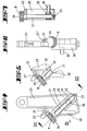
- the lock has one lock box-like housing 1, the lock base 2 in the corner areas has screw holes 3 to the lock with its back lying on the inside of the door attach a locker door, not shown to be able to.
- the lock housing expands towards the top 1 to a hood 4 trapezoidal in plan an upward wall 5 is on the inside by means of an interchangeable coin tray 6, which a not illustrated, calibrated slot for a coin 7.
- a bolt in the lock housing 1 8 led is composed of a penetrating a side wall of the lock housing 1 Bolt head 8 'and which is within the lock housing led bar tail 8 ''. This is with a back open longitudinal slot 9 equipped in the one Uniform guide material starting from the lock base 2 10 protrudes.
- the bolt tail 8 ′′ has a transverse to the bolt displacement direction Driving slot 11, in which a coupling pin 12 of a driving wing 13th protrudes.
- the latter is non-rotatable with the free end of a cylinder core 14 of a lock cylinder 15 connected.
- the locking cylinder 15 is fixed on one the lock mechanism covering, by means of a fastening screw 46 locked on the lock housing 1 Lock cover 16. In the assembled position of the lock passes through the lock cylinder 15 a diameter adapted Opening the locker door or the like.
- the Lock cylinder 15 is otherwise such that with bolt 8 closed, that of the cylinder core 14 recorded key 17 is not removable, according to the twisted position due to the fact that the core pins are not with the body pins swear.
- a locking of the bolt 8 is by a pawl 18 prevented.
- the bearing pin 19 is located above the bar 8 and is a material-uniform component of the lock housing 1, which with the hood 4th is injection molded from plastic. That in the direction of the bolt tail 8 '' facing free end of a torsion spring F pawl 18 loaded clockwise is with a pointing in the direction of the castle floor 2 Control shoulder 20 equipped, the latter one Opening 21 of the bolt tail 8 '' passes through and is supported on a lower edge of the opening 21. The opening has transversely to the bolt displacement direction arranged locking edges 21 ', 21' 'for Cooperation with the control shoulder 20 of the pawl 18. The between the locking edges 21 ', 21' ' extending rear area of the opening 21 continues in an alternative niche 21 '' '.
- the latch 8 carries one integrally molded pin 22 around which a single-arm rocker 23 is mounted.
- On the free end of the rocker 23 has a slope directed to the direction of displacement of the bolt 8 Beam 24, the longitudinal slot in both embodiments 25 owns. Downward goes from the bar 24 a stop projection 26.
- a tie tail 8 '' assigned leaf spring 28 acts on the Swing 23 in the direction of a stop between the Stop projection 26 and shoulder 27.
- the lock housing 1 forms below the bolt 8 Money return pocket 30.
- the lock 1 to 7 passes through a threaded spindle 31 the longitudinal slot 25 and is in the end regions of the beam 24 rotatably mounted.
- the person in question axial immovability results from a the lower end of the beam 24 penetrating safety atift 32 in cooperation with an annular groove 33 of the threaded spindle 31.
- the opposite of the annular groove 33 End of the threaded spindle 31 carries the knurled wheel 34, their knurling R in the longitudinal direction of the threaded spindle 31 runs.
- the threaded spindle 31 extends through it Internal thread 35 designed as a driver pin 36 Driver. By turning a rotating handle forming knurled wheel 34 is accompanied by a Displacement of the driver pin 36, depending on the Direction of rotation of the threaded spindle 31.
- the respective rotational position of the knurled wheel 24 is by means of of a cam 37 can be blocked.
- the latter is as in the rocker 23 designed screwed cams. in the essentially it has a circular layout with a flat 37 '. Does the flattening 37 ' transverse to the longitudinal direction of the threaded spindle 31, thus the area aligned with a circular line occurs of the cam 37 in locking engagement with the knurling R and thus blocks a rotational displacement of the Knurled wheel 34.
- the driver pin 36 is the one support for the coin 7 thrown into the lock.
- the other Support is formed by a bolt 8 made of the same material molded support shoulder 38, which, how also the driver pin 36 up to the lock base 2 enough.
- the distance between the support shoulder 38 and the driver pin 36 is less than the diameter the inserted coin 7 so that it does not fall through, but in an intended control position is held.
- the stop projection occurs at the end phase of the bolt connection 26 the rocker in front of the stop 29 of the castle ceiling 16, whereupon the distance between the support shoulder 38 and driving pin 36 is larger than the diameter the coin 7.
- This causes the latter to fall out of its Steering position, slides down and is controlled by a Support bar 40 of the lock housing 1 held.
- the coin 7 is thus in a controlled intermediate position, from which it is not yet released.
- the key is 17th removable from the cylinder core.
- the bolt 8 takes the coin 7th with, whereupon this in the below the bar 8th arranged money return tray 30 falls. With the closing the bolt 8 also sweeps the rocker 23 the driver pin 36 back to its starting position.
- the threaded spindle 31 is therefore not at a rotational displacement locked so that by means of a through the access opening 41 fingers passed through a rotational displacement the threaded spindle 31 can be connected with a longitudinal movement of the driver pin 36 in the Position according to FIG. 8, whereby the distance between the Driving pin 36 and the support shoulder 38 lower becomes. The distance between also decreases the driver pin 36 and the control shoulder 20 of the Pawl 18. It can therefore, as illustrated in Fig. 8 is, by means of the smaller-diameter coin 7 ' also the pawl 18 in a release position to be raised to latch 8, which is the pre-closing of Riegel allowed.
- any indicators on one longitudinal flank of the Longitudinal slot 25 can be different in diameter Coins correspond to one currency, so this is one Relief when moving. It's understandable, that a corresponding change also changed Coin trays require with appropriately calibrated entry slots.
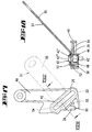
- the driver pin 42 is formed as a screw, which a support section 42 'for the coin 7', a threaded portion 42 '' and a screw head 42 '' 'composed.
- the threaded portion 42 '' passes through a hex nut 44 which is in a rear Elongated hole 48 of a rocker 49 rests against rotation.
- This lock part designed as a rocker 49 forms a plug-in profile 50 for a precise position fixation a driving pin setting gauge 51.
- the Plug-in profiling 50 is used for positive locking an angled insertion lug 52 of the driver pin setting gauge 51.
- the insertion flag 52 closes at one overlapping the longitudinal slot 25
- Angle leg 53 which in the insertion profile 50 engaging insert flag 52 flat on the the castle ceiling 16 facing broad side of the rocker 49 rests, cf. in particular Fig. 18.
- This angle leg 53 there is a coin-specifically arranged Adjustment opening 54. Their position is the respective Coin diameter adapted to which coin diameter the lock should be set.
- the diameter the adjustment opening 54 is chosen so large that the Screw head 42 '' 'is positively received.
- the setting of the driving pin 42 requires if the tension position should be, the loosening of the Screw. Then the driver pin setting gauge 51 to bring to the rocker 49 in that: the insertion flag 52 engages in the insertion profile 50. This is possible due to the access opening 56 the castle ceiling 16 '. The screw head 42 '' 'is in to shift aligned position to the adjustment opening 54. Then there is the driving pin designed as a screw 42 bring in the clamping position, which increases the distance between driver pin 42 and support shoulder 38 is set.
- a coin feed channel 57 is to be carried out, which is in the level of an inserted Coin 7 'extends, ie adjacent to the lock base 2 is.
- This coin guide member 57 extends rearward of the driver pin 42. It concerns regarding the coin gate 57 around one lever arm double-armed, pivotable about a housing-fixed axis 58 Coin guide lever 59.
- the other lever arm 60 acts together with locking openings 61 to 64 of a coin support wall 65 of the hood 4. In the present case, the Lever arm 60 snaps into the snap opening 63. In this Position is ensured by the coin guide element 57, that the coin 7 'as intended in the support position to driving pin 42 and support shoulder 38 reached.
- the lock is on a coin diameter which is smaller than that of Coin 7 ', the lever arm 60 is out of its locked position to bring, then then engaged in To reach locking opening 64. This pivots Münzleitorgan 57 towards the support shoulder 38. Bei the coin positions then become larger bring about in which the lever arm 60 either with the locking opening 62 or the locking opening 61 cooperates.
- Through the coin guide member 57 is in communication with the support shoulder 38 and the driving pin 42 spanned a triangle. The adjustment of the coin counter 57 is possible when the lock cover 16 'is installed, since the lever arm 60 is accessible.
- the coin 7 'in a controlled To hold the position is to change the cross section of the coin on the lower edge of the bolt 8 through to make a support projection 66 changeable.
- the Support projection 66 is one of the threaded shaft Screw 67 formed.
- the Bolt 8 on its lower edge two threaded holes 68, 69 out.
- the lock is set to the coin 7 ' the screw 67 is screwed into the threaded bore 69.
- the bolt 8 starting from the position 15, locked in the position shown in FIG. 16, the rocker 49 remains in the pre-closing movement stand and release the coin 7 'from falling off, which is on the one hand with the edge of the support bar 40 and on the other hand is supported on the support projection 66. see. Fig. 16.
- the coin 7 ' is therefore in one controlled intermediate position held. Not until Closing the bolt 8 is the coin failure cross section with the latch largely closed large that the coin 7 'falls into the money return compartment 30.
- the lock is set on a coin, its diameter is smaller than that of the coin 7 ' screw the screw 67 into the threaded bore 68. If the coin diameter is larger than the diameter the coin 7 ', the screw 67 is complete unscrew from the threaded bore 69.
- the conversion of the screw 67 can with the lock cover installed 16 'can be made.
- the castle ceiling has 16 'has a tool access opening on its lower edge 70.
Applications Claiming Priority (2)
| Application Number | Priority Date | Filing Date | Title |
|---|---|---|---|
| DE29815294U | 1998-08-26 | ||
| DE29815294U DE29815294U1 (de) | 1998-08-26 | 1998-08-26 | Schloß mit nach Münzeinwurf zu betätigender Schloßfunktion |
Publications (2)
| Publication Number | Publication Date |
|---|---|
| EP0982694A1 true EP0982694A1 (fr) | 2000-03-01 |
| EP0982694B1 EP0982694B1 (fr) | 2003-10-15 |
Family
ID=8061780
Family Applications (1)
| Application Number | Title | Priority Date | Filing Date |
|---|---|---|---|
| EP99116332A Expired - Lifetime EP0982694B1 (fr) | 1998-08-26 | 1999-08-19 | Serrure activée par pièce de monnaie |
Country Status (3)
| Country | Link |
|---|---|
| EP (1) | EP0982694B1 (fr) |
| AT (1) | ATE252261T1 (fr) |
| DE (2) | DE29815294U1 (fr) |
Cited By (1)
| Publication number | Priority date | Publication date | Assignee | Title |
|---|---|---|---|---|
| DE10350951B4 (de) * | 2003-10-30 | 2008-02-07 | Schulte-Schlagbaum Ag | Schloss mit nach Münzeinwurf zu betätigender Schließfunktion |
Families Citing this family (1)
| Publication number | Priority date | Publication date | Assignee | Title |
|---|---|---|---|---|
| DE102017113463B3 (de) | 2017-06-20 | 2018-07-12 | W&F Locks Ohg | Hebelschloss |
Citations (4)
| Publication number | Priority date | Publication date | Assignee | Title |
|---|---|---|---|---|
| DE2836486A1 (de) | 1978-08-21 | 1980-03-06 | Schulte Schlagbaum Ag | Schloss mit nach muenzeinwurf zu betaetigender schliessfunktion |
| CH631022A5 (en) * | 1978-06-14 | 1982-07-15 | Dom Ag | Coin-operated door lock, especially for cloakroom cupboards |
| EP0831437A2 (fr) * | 1996-09-23 | 1998-03-25 | Sistemas y Tecnicas de Seguridad, S.A. | Serrure activée par pièce de monnaie |
| EP0945836A2 (fr) * | 1998-03-10 | 1999-09-29 | Assa Ab | Serrure actionnée par pièce |
Family Cites Families (2)
| Publication number | Priority date | Publication date | Assignee | Title |
|---|---|---|---|---|
| US3938640A (en) * | 1975-03-05 | 1976-02-17 | American Locker Company, Inc. | Coin operated lock |
| DE3124180A1 (de) * | 1981-06-19 | 1982-12-30 | Schulte-Schlagbaum Ag, 5620 Velbert | Schloss mit nach muenzeinwurf zu betaetigender schliessfunktion |
-
1998
- 1998-08-26 DE DE29815294U patent/DE29815294U1/de not_active Expired - Lifetime
-
1999
- 1999-08-19 DE DE59907355T patent/DE59907355D1/de not_active Expired - Lifetime
- 1999-08-19 EP EP99116332A patent/EP0982694B1/fr not_active Expired - Lifetime
- 1999-08-19 AT AT99116332T patent/ATE252261T1/de not_active IP Right Cessation
Patent Citations (4)
| Publication number | Priority date | Publication date | Assignee | Title |
|---|---|---|---|---|
| CH631022A5 (en) * | 1978-06-14 | 1982-07-15 | Dom Ag | Coin-operated door lock, especially for cloakroom cupboards |
| DE2836486A1 (de) | 1978-08-21 | 1980-03-06 | Schulte Schlagbaum Ag | Schloss mit nach muenzeinwurf zu betaetigender schliessfunktion |
| EP0831437A2 (fr) * | 1996-09-23 | 1998-03-25 | Sistemas y Tecnicas de Seguridad, S.A. | Serrure activée par pièce de monnaie |
| EP0945836A2 (fr) * | 1998-03-10 | 1999-09-29 | Assa Ab | Serrure actionnée par pièce |
Cited By (1)
| Publication number | Priority date | Publication date | Assignee | Title |
|---|---|---|---|---|
| DE10350951B4 (de) * | 2003-10-30 | 2008-02-07 | Schulte-Schlagbaum Ag | Schloss mit nach Münzeinwurf zu betätigender Schließfunktion |
Also Published As
| Publication number | Publication date |
|---|---|
| EP0982694B1 (fr) | 2003-10-15 |
| DE59907355D1 (de) | 2003-11-20 |
| ATE252261T1 (de) | 2003-11-15 |
| DE29815294U1 (de) | 2000-01-05 |
Similar Documents
| Publication | Publication Date | Title |
|---|---|---|
| DE3447154C2 (de) | Drehsicherung für ein drehbar gelagertes Werkzeug, insbesondere ein Schneidwerkzeug eines Freischneidegerätes | |
| EP2029393B1 (fr) | Dispositif obturateur | |
| WO2007041736A1 (fr) | Ferrure pour abattant | |
| DE112007000324T5 (de) | Türeingangsschloss | |
| DE10008277A1 (de) | Schließvorrichtung | |
| DE19803232A1 (de) | Träger für Fahrzeuge | |
| DE19742511C2 (de) | Schubstangenverschluß für eine an einem Schaltschrank-Korpus angelenkte Schranktüre | |
| DE2931808A1 (de) | Tuerschloss | |
| EP0982694B1 (fr) | Serrure activée par pièce de monnaie | |
| EP1477625A1 (fr) | Serrure de porte pour verrou lustre | |
| DE3243029A1 (de) | Versenkbarer verschluss fuer schaltschranktueren | |
| DE4315452A1 (de) | Verschluß zur zentralen Ver- und Entriegelung von Schubladen | |
| DE3606347C1 (en) | Exterior grip for motor-vehicle doors | |
| DE3124180C2 (fr) | ||
| DE60218261T2 (de) | Mechanismus für die kontrollierte Schliessung eines Deckels | |
| EP0341561A2 (fr) | Serrure à pêne et cylindre actionné par une clé | |
| EP0239855B1 (fr) | Serrure pour porte, fenêtre ou similaire | |
| DE3407073A1 (de) | Tuerschloss mit riegel und falle | |
| CH646806A5 (en) | Lock with a locking function to be actuated after coin insertion | |
| DE1678147C3 (de) | Drücker zum Öffnen eines Haftverschlusses an Türen von Schränken | |
| DE19541942C1 (de) | Rechts und links verwendbares Türschloß | |
| EP1024240B1 (fr) | Dispositif de verrouillage | |
| AT525067B1 (de) | Beschlag zur bewegbaren Lagerung eines Schwenkelementes relativ zu einem stationären Träger | |
| DE19855780C2 (de) | Verschließmechanismus für eine im Fahrgastraum eines Kraftfahrzeuges angeordnete Schublade | |
| DE381647C (de) | Sicherheitsschloss |
Legal Events
| Date | Code | Title | Description |
|---|---|---|---|
| PUAI | Public reference made under article 153(3) epc to a published international application that has entered the european phase |
Free format text: ORIGINAL CODE: 0009012 |
|
| AK | Designated contracting states |
Kind code of ref document: A1 Designated state(s): AT BE CH CY DE DK ES FI FR GB GR IE IT LI LU MC NL PT SE |
|
| AX | Request for extension of the european patent |
Free format text: AL;LT;LV;MK;RO;SI |
|
| 17P | Request for examination filed |
Effective date: 20000810 |
|
| AKX | Designation fees paid |
Free format text: AT BE CH CY DE DK ES FI FR GB GR IE IT LI LU MC NL PT SE |
|
| 17Q | First examination report despatched |
Effective date: 20020219 |
|
| GRAH | Despatch of communication of intention to grant a patent |
Free format text: ORIGINAL CODE: EPIDOS IGRA |
|
| GRAH | Despatch of communication of intention to grant a patent |
Free format text: ORIGINAL CODE: EPIDOS IGRA |
|
| GRAA | (expected) grant |
Free format text: ORIGINAL CODE: 0009210 |
|
| AK | Designated contracting states |
Kind code of ref document: B1 Designated state(s): AT BE CH CY DE DK ES FI FR GB GR IE IT LI LU MC NL PT SE |
|
| PG25 | Lapsed in a contracting state [announced via postgrant information from national office to epo] |
Ref country code: IE Free format text: LAPSE BECAUSE OF FAILURE TO SUBMIT A TRANSLATION OF THE DESCRIPTION OR TO PAY THE FEE WITHIN THE PRESCRIBED TIME-LIMIT Effective date: 20031015 Ref country code: FI Free format text: LAPSE BECAUSE OF FAILURE TO SUBMIT A TRANSLATION OF THE DESCRIPTION OR TO PAY THE FEE WITHIN THE PRESCRIBED TIME-LIMIT Effective date: 20031015 Ref country code: CY Free format text: LAPSE BECAUSE OF FAILURE TO SUBMIT A TRANSLATION OF THE DESCRIPTION OR TO PAY THE FEE WITHIN THE PRESCRIBED TIME-LIMIT Effective date: 20031015 |
|
| REG | Reference to a national code |
Ref country code: GB Ref legal event code: FG4D Free format text: NOT ENGLISH Ref country code: CH Ref legal event code: EP |
|
| REG | Reference to a national code |
Ref country code: IE Ref legal event code: FG4D Free format text: GERMAN |
|
| REG | Reference to a national code |
Ref country code: CH Ref legal event code: NV Representative=s name: PATMED AG |
|
| REF | Corresponds to: |
Ref document number: 59907355 Country of ref document: DE Date of ref document: 20031120 Kind code of ref document: P |
|
| GBT | Gb: translation of ep patent filed (gb section 77(6)(a)/1977) |
Effective date: 20031117 |
|
| PG25 | Lapsed in a contracting state [announced via postgrant information from national office to epo] |
Ref country code: SE Free format text: LAPSE BECAUSE OF FAILURE TO SUBMIT A TRANSLATION OF THE DESCRIPTION OR TO PAY THE FEE WITHIN THE PRESCRIBED TIME-LIMIT Effective date: 20040115 Ref country code: GR Free format text: LAPSE BECAUSE OF FAILURE TO SUBMIT A TRANSLATION OF THE DESCRIPTION OR TO PAY THE FEE WITHIN THE PRESCRIBED TIME-LIMIT Effective date: 20040115 Ref country code: DK Free format text: LAPSE BECAUSE OF FAILURE TO SUBMIT A TRANSLATION OF THE DESCRIPTION OR TO PAY THE FEE WITHIN THE PRESCRIBED TIME-LIMIT Effective date: 20040115 |
|
| PG25 | Lapsed in a contracting state [announced via postgrant information from national office to epo] |
Ref country code: ES Free format text: LAPSE BECAUSE OF FAILURE TO SUBMIT A TRANSLATION OF THE DESCRIPTION OR TO PAY THE FEE WITHIN THE PRESCRIBED TIME-LIMIT Effective date: 20040126 |
|
| ET | Fr: translation filed | ||
| REG | Reference to a national code |
Ref country code: IE Ref legal event code: FD4D |
|
| PG25 | Lapsed in a contracting state [announced via postgrant information from national office to epo] |
Ref country code: LU Free format text: LAPSE BECAUSE OF NON-PAYMENT OF DUE FEES Effective date: 20040819 Ref country code: AT Free format text: LAPSE BECAUSE OF NON-PAYMENT OF DUE FEES Effective date: 20040819 |
|
| PLBE | No opposition filed within time limit |
Free format text: ORIGINAL CODE: 0009261 |
|
| STAA | Information on the status of an ep patent application or granted ep patent |
Free format text: STATUS: NO OPPOSITION FILED WITHIN TIME LIMIT |
|
| PG25 | Lapsed in a contracting state [announced via postgrant information from national office to epo] |
Ref country code: MC Free format text: LAPSE BECAUSE OF NON-PAYMENT OF DUE FEES Effective date: 20040831 Ref country code: LI Free format text: LAPSE BECAUSE OF NON-PAYMENT OF DUE FEES Effective date: 20040831 Ref country code: CH Free format text: LAPSE BECAUSE OF NON-PAYMENT OF DUE FEES Effective date: 20040831 Ref country code: BE Free format text: LAPSE BECAUSE OF NON-PAYMENT OF DUE FEES Effective date: 20040831 |
|
| 26N | No opposition filed |
Effective date: 20040716 |
|
| BERE | Be: lapsed |
Owner name: *SCHULTE-SCHLAGBAUM A.G. Effective date: 20040831 |
|
| PG25 | Lapsed in a contracting state [announced via postgrant information from national office to epo] |
Ref country code: NL Free format text: LAPSE BECAUSE OF NON-PAYMENT OF DUE FEES Effective date: 20050301 |
|
| REG | Reference to a national code |
Ref country code: CH Ref legal event code: PL |
|
| PG25 | Lapsed in a contracting state [announced via postgrant information from national office to epo] |
Ref country code: FR Free format text: LAPSE BECAUSE OF NON-PAYMENT OF DUE FEES Effective date: 20050429 |
|
| NLV4 | Nl: lapsed or anulled due to non-payment of the annual fee |
Effective date: 20050301 |
|
| REG | Reference to a national code |
Ref country code: FR Ref legal event code: ST |
|
| PG25 | Lapsed in a contracting state [announced via postgrant information from national office to epo] |
Ref country code: IT Free format text: LAPSE BECAUSE OF NON-PAYMENT OF DUE FEES;WARNING: LAPSES OF ITALIAN PATENTS WITH EFFECTIVE DATE BEFORE 2007 MAY HAVE OCCURRED AT ANY TIME BEFORE 2007. THE CORRECT EFFECTIVE DATE MAY BE DIFFERENT FROM THE ONE RECORDED. Effective date: 20050819 |
|
| BERE | Be: lapsed |
Owner name: *SCHULTE-SCHLAGBAUM A.G. Effective date: 20040831 |
|
| PG25 | Lapsed in a contracting state [announced via postgrant information from national office to epo] |
Ref country code: PT Free format text: LAPSE BECAUSE OF NON-PAYMENT OF DUE FEES Effective date: 20040315 |
|
| PGFP | Annual fee paid to national office [announced via postgrant information from national office to epo] |
Ref country code: GB Payment date: 20090903 Year of fee payment: 11 |
|
| GBPC | Gb: european patent ceased through non-payment of renewal fee |
Effective date: 20100819 |
|
| PG25 | Lapsed in a contracting state [announced via postgrant information from national office to epo] |
Ref country code: GB Free format text: LAPSE BECAUSE OF NON-PAYMENT OF DUE FEES Effective date: 20100819 |
|
| PGFP | Annual fee paid to national office [announced via postgrant information from national office to epo] |
Ref country code: DE Payment date: 20150817 Year of fee payment: 17 |
|
| REG | Reference to a national code |
Ref country code: DE Ref legal event code: R119 Ref document number: 59907355 Country of ref document: DE |
|
| PG25 | Lapsed in a contracting state [announced via postgrant information from national office to epo] |
Ref country code: DE Free format text: LAPSE BECAUSE OF NON-PAYMENT OF DUE FEES Effective date: 20170301 |