EP0982130B1 - Einrichtung zur Registerkontrolle - Google Patents
Einrichtung zur Registerkontrolle Download PDFInfo
- Publication number
- EP0982130B1 EP0982130B1 EP99115435A EP99115435A EP0982130B1 EP 0982130 B1 EP0982130 B1 EP 0982130B1 EP 99115435 A EP99115435 A EP 99115435A EP 99115435 A EP99115435 A EP 99115435A EP 0982130 B1 EP0982130 B1 EP 0982130B1
- Authority
- EP
- European Patent Office
- Prior art keywords
- register
- contact
- cylinder
- printing
- signal
- Prior art date
- Legal status (The legal status is an assumption and is not a legal conclusion. Google has not performed a legal analysis and makes no representation as to the accuracy of the status listed.)
- Expired - Lifetime
Links
- 238000007639 printing Methods 0.000 claims abstract description 43
- 238000011156 evaluation Methods 0.000 claims abstract description 17
- 238000001208 nuclear magnetic resonance pulse sequence Methods 0.000 claims description 2
- 238000003780 insertion Methods 0.000 abstract description 4
- 230000037431 insertion Effects 0.000 abstract description 4
- 238000007645 offset printing Methods 0.000 abstract description 3
- 230000000284 resting effect Effects 0.000 abstract 1
- 238000000034 method Methods 0.000 description 5
- 230000008054 signal transmission Effects 0.000 description 3
- 229910052782 aluminium Inorganic materials 0.000 description 2
- XAGFODPZIPBFFR-UHFFFAOYSA-N aluminium Chemical compound [Al] XAGFODPZIPBFFR-UHFFFAOYSA-N 0.000 description 2
- 230000001960 triggered effect Effects 0.000 description 2
- 230000005540 biological transmission Effects 0.000 description 1
- 239000003086 colorant Substances 0.000 description 1
- 238000010276 construction Methods 0.000 description 1
- 238000011161 development Methods 0.000 description 1
- 230000018109 developmental process Effects 0.000 description 1
- 238000010586 diagram Methods 0.000 description 1
- 230000000694 effects Effects 0.000 description 1
- 239000000463 material Substances 0.000 description 1
- 229910052751 metal Inorganic materials 0.000 description 1
- 239000002184 metal Substances 0.000 description 1
- 238000010079 rubber tapping Methods 0.000 description 1
- 230000000007 visual effect Effects 0.000 description 1
Images

Classifications
-
- B—PERFORMING OPERATIONS; TRANSPORTING
- B41—PRINTING; LINING MACHINES; TYPEWRITERS; STAMPS
- B41F—PRINTING MACHINES OR PRESSES
- B41F27/00—Devices for attaching printing elements or formes to supports
- B41F27/005—Attaching and registering printing formes to supports
-
- B—PERFORMING OPERATIONS; TRANSPORTING
- B41—PRINTING; LINING MACHINES; TYPEWRITERS; STAMPS
- B41F—PRINTING MACHINES OR PRESSES
- B41F27/00—Devices for attaching printing elements or formes to supports
- B41F27/12—Devices for attaching printing elements or formes to supports for attaching flexible printing formes
- B41F27/1206—Feeding to or removing from the forme cylinder
-
- B—PERFORMING OPERATIONS; TRANSPORTING
- B41—PRINTING; LINING MACHINES; TYPEWRITERS; STAMPS
- B41P—INDEXING SCHEME RELATING TO PRINTING, LINING MACHINES, TYPEWRITERS, AND TO STAMPS
- B41P2227/00—Mounting or handling printing plates; Forming printing surfaces in situ
- B41P2227/30—Detecting the correct position of printing plates on the cylinder
-
- Y—GENERAL TAGGING OF NEW TECHNOLOGICAL DEVELOPMENTS; GENERAL TAGGING OF CROSS-SECTIONAL TECHNOLOGIES SPANNING OVER SEVERAL SECTIONS OF THE IPC; TECHNICAL SUBJECTS COVERED BY FORMER USPC CROSS-REFERENCE ART COLLECTIONS [XRACs] AND DIGESTS
- Y10—TECHNICAL SUBJECTS COVERED BY FORMER USPC
- Y10S—TECHNICAL SUBJECTS COVERED BY FORMER USPC CROSS-REFERENCE ART COLLECTIONS [XRACs] AND DIGESTS
- Y10S101/00—Printing
- Y10S101/36—Means for registering or alignment of print plates on print press structure
Definitions
- the invention relates to a device for register control according to the preamble of claim 1.
- the Printing forms or printing plates with one each at the beginning and end of printing assigned clamping device held on a plate or plate cylinder.
- the register-correct overprint is of the individual colors through the individual printing forms of crucial Importance.
- the individual printing forms are precisely positioned on the Attach the form or plate cylinder.
- register systems for this have been developed, for example, in the pressure start clamping device Arranged pins or stops, which with the Punched out leading edge of the printing form or printing plate interact.
- register pins or register stops are designed to be electrically pollable. This can be done in easily done in that the register pins or the stops electrically insulated from the clamping rail or the entire cylinder are arranged so that by registering a metallic Printing form or printing plate, an electrical circuit is closed. The The system is then in register with the cylinder or the register stops attached illuminants (LEDs) can be displayed. Such a configuration is suitable for visual control by hand on a cylinder printing forms to be applied.
- LEDs illuminants
- the signal is the Evaluate register query by a controller in order to after the supply of a the new printing plate and the establishment of the register-compliant system Closing rail to fasten the plate.
- Which the signal evaluating, closing the rail and other processes the control triggering the change process is outside the plate or Form cylinder arranged so that the signal of the electrically interrogated register pins is to be led out of the rotatably mounted cylinder.
- EP 0 551 976 A1 describes a device for the electrical register interrogation known, in which the signals of the electrically interrogable register pins via am Plate cylinder attached contact surfaces are grinded out.
- corresponding contacts for example adjustable in the form of roles, these contacts with a the signals evaluating circuit are connected.
- the disadvantage here is that for Contact space corresponding space on the cylinder and on the frame side for the and switchable contacts (rollers) must be provided.
- the mounted and removable Contacts also increase construction costs. Pollution of the Contact areas or the contacts (rollers) that can be placed on the contact areas also causes the risk of incorrect signal transmission here.
- DE 43 39 344 C1 describes a device for automated changing known from printing plates of a printing press.
- a new one to be added Pressure plate provided in a protection on stops and via a to the Cylinder-adjustable guiding device in the open clamping rail at the start of printing introduced. After inserting the start of printing the plate into the Clamping rail and the clamping of the front edge of the board is through the forward rotation of the cylinder mounted on this.
- the pressure start clamping rail as well as during mounting Pressure plate with its middle or rear part still in contact with the protection on. How the signals are arranged in the pressure start clamping rail electrically interrogable register pins are led out of the cylinder not described in this document.
- the object of the present invention is therefore a device for register control to expand in accordance with the preamble of claim 1 so that simple and secure signal transmission is possible.
- the in the cylinder (plate cylinder / plate cylinder) electrically insulated register pins with a signal generator in Are connected so that these with pulses of predetermined duration and frequency are acted upon.
- the signals are routed out via the metallic pressure plate, which is done using a contact grinder, a brush or another voltage tap connected to the control unit fixed to the frame becomes.
- the provided with the new pressure plate during insertion Potential or the pulse train applied register pins cause that after Contact of the pressure plate, i.e. the register-compliant system, this also the Potential or the pulse train has or occupies.
- this is the contact acting on the back of the metallic pressure plate (aluminum) Potential or the pulse sequence can be tapped and sent to a stationary evaluation unit routable.
- the electrically isolated from the Cylinder and the clamping rail together with the pressure plate fed to the register pins now takes the potential or the potential of the pulse train of the individual register pins depending on which of the register pins the plate is in first Contact comes.
- the stationary evaluation unit can be used to determine which one of the register pins the printing plate is first in register and whether this is after all, it is the case with both. Only in this case is one of the Evaluation unit downstream control triggered the clamping process. With the The evaluation unit can also have a display device in signal connection stand, by which it can be indicated whether the pressure plate is in register and at which of the register pins this is done.
- the tapping of the signals on the back of the printing plate in particular can according to the invention by electrically conductive rollers, grinders or brushes.
- the present invention is preferably in a known manner and printing plate changer cited in the description instructions attached, where the new pressure plate to be fed before changing into protection is provided and during insertion or during Mounting on the cylinder is still in contact with parts of the protection or is pulled through this.
- Aluminum printing plates are usually used in sheetfed offset printing machines, which are uncoated on the non-printing back.
- An in itself Pressure plate changer designed in a known manner can therefore be used the present invention by attaching a roller, a sliding contact or an electrically conductive brush.
- the role, the sliding contact or the brush is so in the the pressure plate changer forming protection arranged so that the electrical potential of the pressure plate the back of the panel can be tapped and the stationary evaluation and control unit is feedable.
- the parts that conduct the pressure plate are electrically insulated, i.e. made of electrically non-conductive plastic (or coated metal).
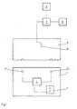
- a cylinder 1 (plate cylinder, printing form cylinder) indicated in principle points in one not shown and assigned to the start of printing of the printing plate 6
- Clamping device two register pins 2.1, 2.2, which are electrically insulated opposite the clamping device and the entire cylinder 1 are attached.
- the register pins 2.1, 2.2 are in signal connection with a signal generator 4.
- the signal generator 4 within the cylinder 1 is also connected to a power supply in the form of a battery.
- the pressure plate 5 to be fed to the cylinder 1 has on the front Edge two U-shaped cut-outs, which in a manner known per se the register pins 2.1, 2.2 work together.
- the back of the pressure plate 5 is assigned a contact 6, via which the potential of the pressure plate 5 can be tapped and an evaluation unit 7 arranged fixed to the frame can be fed.
- the evaluation unit 7 is in signal connection with a display 9, and also on the output side with a controller 8, through which the entire printing plate change process and in particular the opening and closing of the pressure start clamping device can be triggered in cylinder 1.
- FIG. 1 shows the position of the pressure plate 1 without contact with the register pins 2.1, 2.2 arranged electrically insulated in the cylinder 1.
- Figure 2 shows a side view of a part of the cylinder 1 with the to electrically insulated register pins 2.1, 2.2 adjacent pressure plate 5.
- the pressure plate 5 is protected by a not shown over a with the printing Side of the pressure plate 5 cooperating roller 10 fed to the cylinder 1.
- the guide roller 10 is preferably made of electrically insulated material manufactured and carries the printing plate 5 on its printing side.
- the rotatable Roll 10 opposite in the protection, not shown, and thus with the not Coated back of the pressure plate 5 is cooperating in the form of a Sliding contact, an electrically conductive roller or a brush a contact 6 attached through which the electrical potential of the register pins 2.1, 2.2 can be detected and can be forwarded to the stationary evaluation unit 7.
- the clamping device in cylinder 1 is closed and the pressure plate 5 mounted on the cylinder 1.
Landscapes
- Supply, Installation And Extraction Of Printed Sheets Or Plates (AREA)
- Inking, Control Or Cleaning Of Printing Machines (AREA)
- Communication Control (AREA)
- Time-Division Multiplex Systems (AREA)
Description
- Fig. 1
- ein Prinzipschaltbild der vorliegenden Erfindung und
- Fig. 2
- die Anordnung eines Schleifkontaktes sowie dessen Einwirkung auf die Druckplatten-Rückseite.
- 1
- Zylinder (Plattenzylinder, Formzylinder)
- 2.1
- Registerstift
- 2.2
- Registerstift
- 3
- Stromversorgung
- 4
- Signalgeber
- 5
- Druckplatte
- 6
- Kontakt (Schleifkontakt, Kontaktrolle, Bürste)
- 7
- Auswerteeinheit
- 8
- Steuerung
- 9
- Anzeige
- 10
- Führungsrolle (Druckplatte 5)
Claims (8)
- Einrichtung zur Registerkontrolle für den Zylinder einer Druckmaschine, insbesondere für den Platten- bzw. Formzylinder einer Bogenoffsetdruckmaschine, mit einem gegenüber dem Zylinder elektrisch isoliert angebrachten Registerstift, dem ein Signal entnehmbar ist, wenn eine elektrisch leitende Druckform registergerecht an diesem anliegt, sowie einer dieses Signal empfangenden stationären Auswerteeinheit,
dadurch gekennzeichnet, daß dem Registerstift (2.1, 2.2) ein Signalgeber (4) zugeordnet ist, vermittels dem die Druckform (5) über den Registerstift (2.1, 2.2) auf ein vorgegebenes Potential verbringbar ist, und daß die stationäre Auswerteeinheit (7) zur Erfassung des Potentials über einen Kontakt (6) mit der Druckform (5) in elektrischer Verbindung steht. - Einrichtung nach Anspruch 1,
dadurch gekennzeichnet, daß der Kontakt (6) mit der Rückseite der Druckform (5) zusammenwirkt. - Einrichtung nach Anspruch 1 oder 2,
dadurch gekennzeichnet, daß der Kontakt (6) als Schleifkontakt ausgebildet ist. - Einrichtung nach Anspruch 1 oder 2,
dadurch gekennzeichnet, daß der Kontakt (6) als eine elektrisch leitende Kontaktrolle ausgebildet ist. - Einrichtung nach Anspruch 1 oder 2,
dadurch gekennzeichnet, daß der Kontakt (6) als eine elektrisch leitfähige Bürste ausgebildet ist. - Einrichtung nach einem der vorhergehenden Ansprüche,
dadurch gekennzeichnet, daß dem Kontakt (6) eine auf die druckende Seite der Druckform (5) einwirkende Stützrolle (10) zugeordnet ist. - Einrichtung nach einem der vorhergehenden Ansprüche,
dadurch gekennzeichnet, daß der Registerstift (2.1, 2.2) durch den Signalgeber (4) mit einer vorgegebenen Impulsfolge beaufschlagbar ist. - Einrichtung nach einem der vorhergehenden Ansprüche,
dadurch gekennzeichnet, daß bei zwei im Zylinder (1) angeordneten Registerstiften (2.1, 2.2) diese über den Signalgeber (4) in unterschiedlicher Weise mit Impulsen beaufschlagbar sind, und daß durch die Auswerteeinheit (7) diese Impulse getrennt auswertbar sind.
Applications Claiming Priority (2)
| Application Number | Priority Date | Filing Date | Title |
|---|---|---|---|
| DE19839149 | 1998-08-28 | ||
| DE19839149A DE19839149C1 (de) | 1998-08-28 | 1998-08-28 | Vorrichtung zur registergerechten Plattenanlage |
Publications (2)
| Publication Number | Publication Date |
|---|---|
| EP0982130A1 EP0982130A1 (de) | 2000-03-01 |
| EP0982130B1 true EP0982130B1 (de) | 2002-10-30 |
Family
ID=7879004
Family Applications (1)
| Application Number | Title | Priority Date | Filing Date |
|---|---|---|---|
| EP99115435A Expired - Lifetime EP0982130B1 (de) | 1998-08-28 | 1999-08-05 | Einrichtung zur Registerkontrolle |
Country Status (5)
| Country | Link |
|---|---|
| US (1) | US6032581A (de) |
| EP (1) | EP0982130B1 (de) |
| JP (1) | JP3148204B2 (de) |
| AT (1) | ATE226889T1 (de) |
| DE (2) | DE19839149C1 (de) |
Families Citing this family (5)
| Publication number | Priority date | Publication date | Assignee | Title |
|---|---|---|---|---|
| US6691616B2 (en) * | 1999-05-07 | 2004-02-17 | Heidelberger Druckmaschinen Ag | Device for detecting the position of a printing plate on a cylinder of a rotary printing machine |
| DE10015727A1 (de) * | 2000-03-29 | 2001-10-04 | Koenig & Bauer Ag | Verfahren und Vorrichtung zum sicheren registergerechten Aufspannen einer Druckplatte auf den Plattenzylinder einer Bogendruckmaschine |
| DE102007005338B3 (de) * | 2007-02-02 | 2008-04-17 | Maschinenfabrik Wifag | Rollenrotationsdruckmaschine mit einem Belagspeicher |
| DE102009052093A1 (de) | 2008-12-02 | 2010-06-17 | Heidelberger Druckmaschinen Ag | Verfahren und Vorrichtung zum automatischen Zuführen von Druckplatten |
| US20110192303A1 (en) * | 2010-02-05 | 2011-08-11 | Hines Ryan K | Detection of misregistered printing plate |
Family Cites Families (6)
| Publication number | Priority date | Publication date | Assignee | Title |
|---|---|---|---|---|
| DE4129022A1 (de) * | 1991-08-31 | 1993-03-11 | Heidelberger Druckmasch Ag | Magazin fuer den automatischen druckplattenwechsel |
| JP3194199B2 (ja) * | 1992-01-17 | 2001-07-30 | 株式会社小森コーポレーション | 版胴への刷版装着装置 |
| DE4223908C2 (de) * | 1992-06-30 | 1995-09-28 | Lehner Gmbh | Spannvorrichtung zum Spannen und Verstellen einer Druckplatte auf einem Plattenzylinder |
| DE4338664C2 (de) * | 1993-11-12 | 1995-09-14 | Roland Man Druckmasch | Verfahren und Vorrichtung zum Steuern eines automatisierten Druckplattenwechselvorganges bei Druckmaschinen |
| DE4339344C1 (de) * | 1993-11-18 | 1995-03-30 | Roland Man Druckmasch | Vorrichtung für das automatisierte Wechseln von Druckplatten einer Druckmaschine |
| DE4439623C2 (de) * | 1994-11-05 | 1999-01-14 | Roland Man Druckmasch | Verfahren zum automatischen Zuführen von Druckplatten |
-
1998
- 1998-08-28 DE DE19839149A patent/DE19839149C1/de not_active Expired - Fee Related
-
1999
- 1999-08-05 AT AT99115435T patent/ATE226889T1/de active
- 1999-08-05 DE DE59903232T patent/DE59903232D1/de not_active Expired - Lifetime
- 1999-08-05 EP EP99115435A patent/EP0982130B1/de not_active Expired - Lifetime
- 1999-08-23 US US09/379,273 patent/US6032581A/en not_active Expired - Fee Related
- 1999-08-23 JP JP23611699A patent/JP3148204B2/ja not_active Expired - Fee Related
Also Published As
| Publication number | Publication date |
|---|---|
| JP3148204B2 (ja) | 2001-03-19 |
| DE59903232D1 (de) | 2002-12-05 |
| DE19839149C1 (de) | 2000-01-20 |
| EP0982130A1 (de) | 2000-03-01 |
| ATE226889T1 (de) | 2002-11-15 |
| US6032581A (en) | 2000-03-07 |
| JP2000135778A (ja) | 2000-05-16 |
Similar Documents
| Publication | Publication Date | Title |
|---|---|---|
| DE69303380T3 (de) | Vorrichtung zum Anbringen einer Platte auf einem Plattenzylinder | |
| DE69308951T2 (de) | Vorrichtung zum Montieren einer Druckplatte für eine Druckpresse | |
| EP0582903B1 (de) | Vorrichtung zur Kontrolle der registergerechten Anlage einer Druckplatte auf dem Plattenzylinder von Druckmaschinen, insbesondere Bogenoffsetdruckmaschinen | |
| DE4223908C2 (de) | Spannvorrichtung zum Spannen und Verstellen einer Druckplatte auf einem Plattenzylinder | |
| DE4439623C2 (de) | Verfahren zum automatischen Zuführen von Druckplatten | |
| EP0530612B1 (de) | Vorrichtung für die Uebertragung von elektrischer Energie und von Daten von einem feststehenden Maschinenbauteil auf ein sich drehendes Maschinenbauteil einer Druckmaschine | |
| DE19839149C1 (de) | Vorrichtung zur registergerechten Plattenanlage | |
| EP0724958B1 (de) | Druckmaschine mit herausnehmbaren Bauteilen | |
| EP0655331B1 (de) | Vorrichtung zur Kontrolle der registergerechten Anlage von Druckplatten auf dem Plattenzylinder von Druckmaschinen | |
| EP0955162B1 (de) | Einrichtung zur Registerkontrolle | |
| EP0841160B1 (de) | Signalübertragung innerhalb einer Druckmaschine | |
| EP0982129B1 (de) | Einrichtung zur Registerkontrolle | |
| EP0955163B1 (de) | Einrichtung zur Registerkontrolle | |
| EP0635367B1 (de) | Vorrichtung zum registerhaltigen Ansetzen von Druckplatten auf dem Plattenzylinder von Druckmaschinen | |
| EP1046502B1 (de) | Einrichtung zur Kontrolle der registerechten Anlage von Druckplatten | |
| DE7906800U1 (de) | Bogenrotationsdruckmaschine mit einem im ausleger angeordneten druckwerk | |
| DE3517179A1 (de) | Bogenkontrolleinrichtung | |
| DE402059C (de) | Rotationsgummidruckmaschine fuer mehrfarbigen Bogendruck | |
| EP2114680B1 (de) | Rollenrotationsdruckmaschine mit einem belagspeicher | |
| EP0982128B1 (de) | Stromversorgung für einen Druckmaschinenzylinder | |
| DE2421209A1 (de) | Mehrfarben-rotationsdruckmaschine | |
| DE19754003A1 (de) | Vorrichtung zur Kontrolle der registergerechten Lage einer Druckplatte | |
| EP1046501B1 (de) | Einrichtung zur Kontrolle der Lage von Druckplatten auf den Plattenzylinder von Druckmaschinen | |
| DE29907123U1 (de) | Einrichtung zur Kontrolle der Lage von Druckplatten | |
| DE8907383U1 (de) | Offset-Druckmaschine |
Legal Events
| Date | Code | Title | Description |
|---|---|---|---|
| PUAI | Public reference made under article 153(3) epc to a published international application that has entered the european phase |
Free format text: ORIGINAL CODE: 0009012 |
|
| 17P | Request for examination filed |
Effective date: 19991209 |
|
| AK | Designated contracting states |
Kind code of ref document: A1 Designated state(s): AT BE CH CY DE DK ES FI FR GB GR IE IT LI LU MC NL PT SE |
|
| AX | Request for extension of the european patent |
Free format text: AL;LT;LV;MK;RO;SI |
|
| AKX | Designation fees paid |
Free format text: AT BE CH CY DE DK ES FI FR GB GR IE IT LI LU MC NL PT SE |
|
| GRAG | Despatch of communication of intention to grant |
Free format text: ORIGINAL CODE: EPIDOS AGRA |
|
| GRAG | Despatch of communication of intention to grant |
Free format text: ORIGINAL CODE: EPIDOS AGRA |
|
| GRAH | Despatch of communication of intention to grant a patent |
Free format text: ORIGINAL CODE: EPIDOS IGRA |
|
| GRAH | Despatch of communication of intention to grant a patent |
Free format text: ORIGINAL CODE: EPIDOS IGRA |
|
| 17Q | First examination report despatched |
Effective date: 20020124 |
|
| GRAA | (expected) grant |
Free format text: ORIGINAL CODE: 0009210 |
|
| AK | Designated contracting states |
Kind code of ref document: B1 Designated state(s): AT BE CH CY DE DK ES FI FR GB GR IE IT LI LU MC NL PT SE |
|
| PG25 | Lapsed in a contracting state [announced via postgrant information from national office to epo] |
Ref country code: NL Free format text: LAPSE BECAUSE OF FAILURE TO SUBMIT A TRANSLATION OF THE DESCRIPTION OR TO PAY THE FEE WITHIN THE PRESCRIBED TIME-LIMIT Effective date: 20021030 Ref country code: IT Free format text: LAPSE BECAUSE OF FAILURE TO SUBMIT A TRANSLATION OF THE DESCRIPTION OR TO PAY THE FEE WITHIN THE PRESCRIBED TIME-LIMIT;WARNING: LAPSES OF ITALIAN PATENTS WITH EFFECTIVE DATE BEFORE 2007 MAY HAVE OCCURRED AT ANY TIME BEFORE 2007. THE CORRECT EFFECTIVE DATE MAY BE DIFFERENT FROM THE ONE RECORDED. Effective date: 20021030 Ref country code: IE Free format text: LAPSE BECAUSE OF FAILURE TO SUBMIT A TRANSLATION OF THE DESCRIPTION OR TO PAY THE FEE WITHIN THE PRESCRIBED TIME-LIMIT Effective date: 20021030 Ref country code: GR Free format text: LAPSE BECAUSE OF FAILURE TO SUBMIT A TRANSLATION OF THE DESCRIPTION OR TO PAY THE FEE WITHIN THE PRESCRIBED TIME-LIMIT Effective date: 20021030 Ref country code: FI Free format text: LAPSE BECAUSE OF FAILURE TO SUBMIT A TRANSLATION OF THE DESCRIPTION OR TO PAY THE FEE WITHIN THE PRESCRIBED TIME-LIMIT Effective date: 20021030 |
|
| REF | Corresponds to: |
Ref document number: 226889 Country of ref document: AT Date of ref document: 20021115 Kind code of ref document: T |
|
| REG | Reference to a national code |
Ref country code: GB Ref legal event code: FG4D Free format text: NOT ENGLISH |
|
| REG | Reference to a national code |
Ref country code: CH Ref legal event code: EP |
|
| REG | Reference to a national code |
Ref country code: CH Ref legal event code: NV Representative=s name: E. BLUM & CO. PATENTANWAELTE |
|
| GBT | Gb: translation of ep patent filed (gb section 77(6)(a)/1977) |
Effective date: 20021031 |
|
| REG | Reference to a national code |
Ref country code: IE Ref legal event code: FG4D Free format text: GERMAN |
|
| REF | Corresponds to: |
Ref document number: 59903232 Country of ref document: DE Date of ref document: 20021205 |
|
| ET | Fr: translation filed | ||
| PG25 | Lapsed in a contracting state [announced via postgrant information from national office to epo] |
Ref country code: PT Free format text: LAPSE BECAUSE OF FAILURE TO SUBMIT A TRANSLATION OF THE DESCRIPTION OR TO PAY THE FEE WITHIN THE PRESCRIBED TIME-LIMIT Effective date: 20030130 Ref country code: DK Free format text: LAPSE BECAUSE OF FAILURE TO SUBMIT A TRANSLATION OF THE DESCRIPTION OR TO PAY THE FEE WITHIN THE PRESCRIBED TIME-LIMIT Effective date: 20030130 |
|
| NLV1 | Nl: lapsed or annulled due to failure to fulfill the requirements of art. 29p and 29m of the patents act | ||
| PG25 | Lapsed in a contracting state [announced via postgrant information from national office to epo] |
Ref country code: ES Free format text: LAPSE BECAUSE OF FAILURE TO SUBMIT A TRANSLATION OF THE DESCRIPTION OR TO PAY THE FEE WITHIN THE PRESCRIBED TIME-LIMIT Effective date: 20030429 |
|
| REG | Reference to a national code |
Ref country code: IE Ref legal event code: FD4D Ref document number: 0982130E Country of ref document: IE |
|
| PG25 | Lapsed in a contracting state [announced via postgrant information from national office to epo] |
Ref country code: LU Free format text: LAPSE BECAUSE OF NON-PAYMENT OF DUE FEES Effective date: 20030805 Ref country code: GB Free format text: LAPSE BECAUSE OF NON-PAYMENT OF DUE FEES Effective date: 20030805 Ref country code: CY Free format text: LAPSE BECAUSE OF FAILURE TO SUBMIT A TRANSLATION OF THE DESCRIPTION OR TO PAY THE FEE WITHIN THE PRESCRIBED TIME-LIMIT Effective date: 20030805 |
|
| PG25 | Lapsed in a contracting state [announced via postgrant information from national office to epo] |
Ref country code: SE Free format text: LAPSE BECAUSE OF NON-PAYMENT OF DUE FEES Effective date: 20030806 |
|
| PG25 | Lapsed in a contracting state [announced via postgrant information from national office to epo] |
Ref country code: MC Free format text: LAPSE BECAUSE OF NON-PAYMENT OF DUE FEES Effective date: 20030831 Ref country code: LI Free format text: LAPSE BECAUSE OF NON-PAYMENT OF DUE FEES Effective date: 20030831 Ref country code: CH Free format text: LAPSE BECAUSE OF NON-PAYMENT OF DUE FEES Effective date: 20030831 Ref country code: BE Free format text: LAPSE BECAUSE OF NON-PAYMENT OF DUE FEES Effective date: 20030831 |
|
| PLBE | No opposition filed within time limit |
Free format text: ORIGINAL CODE: 0009261 |
|
| STAA | Information on the status of an ep patent application or granted ep patent |
Free format text: STATUS: NO OPPOSITION FILED WITHIN TIME LIMIT |
|
| 26N | No opposition filed |
Effective date: 20030731 |
|
| BERE | Be: lapsed |
Owner name: *MAN ROLAND DRUCKMASCHINEN A.G. Effective date: 20030831 |
|
| GBPC | Gb: european patent ceased through non-payment of renewal fee |
Effective date: 20030805 |
|
| EUG | Se: european patent has lapsed | ||
| REG | Reference to a national code |
Ref country code: CH Ref legal event code: PL |
|
| PGFP | Annual fee paid to national office [announced via postgrant information from national office to epo] |
Ref country code: FR Payment date: 20050812 Year of fee payment: 7 |
|
| REG | Reference to a national code |
Ref country code: FR Ref legal event code: ST Effective date: 20070430 |
|
| PG25 | Lapsed in a contracting state [announced via postgrant information from national office to epo] |
Ref country code: FR Free format text: LAPSE BECAUSE OF NON-PAYMENT OF DUE FEES Effective date: 20060831 |
|
| PGFP | Annual fee paid to national office [announced via postgrant information from national office to epo] |
Ref country code: DE Payment date: 20100823 Year of fee payment: 12 Ref country code: AT Payment date: 20100812 Year of fee payment: 12 |
|
| REG | Reference to a national code |
Ref country code: DE Ref legal event code: R119 Ref document number: 59903232 Country of ref document: DE Effective date: 20120301 |
|
| REG | Reference to a national code |
Ref country code: DE Ref legal event code: R081 Ref document number: 59903232 Country of ref document: DE Owner name: MANROLAND SHEETFED GMBH, DE Free format text: FORMER OWNER: MANROLAND AG, 63075 OFFENBACH, DE Effective date: 20120510 |
|
| REG | Reference to a national code |
Ref country code: AT Ref legal event code: MM01 Ref document number: 226889 Country of ref document: AT Kind code of ref document: T Effective date: 20110805 |
|
| PG25 | Lapsed in a contracting state [announced via postgrant information from national office to epo] |
Ref country code: AT Free format text: LAPSE BECAUSE OF NON-PAYMENT OF DUE FEES Effective date: 20110805 |
|
| PG25 | Lapsed in a contracting state [announced via postgrant information from national office to epo] |
Ref country code: DE Free format text: LAPSE BECAUSE OF NON-PAYMENT OF DUE FEES Effective date: 20120301 |