EP0981091B1 - Replication de données dans des systèmes de stockage - Google Patents
Replication de données dans des systèmes de stockage Download PDFInfo
- Publication number
- EP0981091B1 EP0981091B1 EP99116045A EP99116045A EP0981091B1 EP 0981091 B1 EP0981091 B1 EP 0981091B1 EP 99116045 A EP99116045 A EP 99116045A EP 99116045 A EP99116045 A EP 99116045A EP 0981091 B1 EP0981091 B1 EP 0981091B1
- Authority
- EP
- European Patent Office
- Prior art keywords
- volume
- copy
- logical
- logical volume
- data
- Prior art date
- Legal status (The legal status is an assumption and is not a legal conclusion. Google has not performed a legal analysis and makes no representation as to the accuracy of the status listed.)
- Expired - Lifetime
Links
- 238000003860 storage Methods 0.000 title claims description 469
- 238000012545 processing Methods 0.000 claims description 202
- 230000015654 memory Effects 0.000 claims description 52
- 238000000034 method Methods 0.000 claims description 50
- 230000006870 function Effects 0.000 claims description 7
- 238000013507 mapping Methods 0.000 claims description 3
- 238000001514 detection method Methods 0.000 claims 1
- 230000001617 migratory effect Effects 0.000 description 50
- 238000010586 diagram Methods 0.000 description 20
- 238000010276 construction Methods 0.000 description 12
- 238000012423 maintenance Methods 0.000 description 8
- 238000012546 transfer Methods 0.000 description 6
- 230000008707 rearrangement Effects 0.000 description 5
- 239000000470 constituent Substances 0.000 description 4
- 238000003491 array Methods 0.000 description 3
- 230000015572 biosynthetic process Effects 0.000 description 3
- 230000008569 process Effects 0.000 description 3
- 230000004044 response Effects 0.000 description 3
- 230000008859 change Effects 0.000 description 2
- 230000010485 coping Effects 0.000 description 2
- 230000002542 deteriorative effect Effects 0.000 description 2
- 238000013508 migration Methods 0.000 description 2
- 230000005012 migration Effects 0.000 description 2
- 238000006243 chemical reaction Methods 0.000 description 1
- 238000007796 conventional method Methods 0.000 description 1
- 239000006185 dispersion Substances 0.000 description 1
- 230000000694 effects Effects 0.000 description 1
- 239000000835 fiber Substances 0.000 description 1
- 230000010365 information processing Effects 0.000 description 1
- 238000004519 manufacturing process Methods 0.000 description 1
- 238000004904 shortening Methods 0.000 description 1
Images


Classifications
-
- G—PHYSICS
- G06—COMPUTING; CALCULATING OR COUNTING
- G06F—ELECTRIC DIGITAL DATA PROCESSING
- G06F11/00—Error detection; Error correction; Monitoring
- G06F11/07—Responding to the occurrence of a fault, e.g. fault tolerance
- G06F11/14—Error detection or correction of the data by redundancy in operation
- G06F11/1402—Saving, restoring, recovering or retrying
- G06F11/1446—Point-in-time backing up or restoration of persistent data
- G06F11/1448—Management of the data involved in backup or backup restore
- G06F11/1451—Management of the data involved in backup or backup restore by selection of backup contents
-
- G—PHYSICS
- G06—COMPUTING; CALCULATING OR COUNTING
- G06F—ELECTRIC DIGITAL DATA PROCESSING
- G06F11/00—Error detection; Error correction; Monitoring
- G06F11/07—Responding to the occurrence of a fault, e.g. fault tolerance
- G06F11/16—Error detection or correction of the data by redundancy in hardware
- G06F11/20—Error detection or correction of the data by redundancy in hardware using active fault-masking, e.g. by switching out faulty elements or by switching in spare elements
- G06F11/2053—Error detection or correction of the data by redundancy in hardware using active fault-masking, e.g. by switching out faulty elements or by switching in spare elements where persistent mass storage functionality or persistent mass storage control functionality is redundant
- G06F11/2056—Error detection or correction of the data by redundancy in hardware using active fault-masking, e.g. by switching out faulty elements or by switching in spare elements where persistent mass storage functionality or persistent mass storage control functionality is redundant by mirroring
- G06F11/2064—Error detection or correction of the data by redundancy in hardware using active fault-masking, e.g. by switching out faulty elements or by switching in spare elements where persistent mass storage functionality or persistent mass storage control functionality is redundant by mirroring while ensuring consistency
-
- G—PHYSICS
- G06—COMPUTING; CALCULATING OR COUNTING
- G06F—ELECTRIC DIGITAL DATA PROCESSING
- G06F11/00—Error detection; Error correction; Monitoring
- G06F11/07—Responding to the occurrence of a fault, e.g. fault tolerance
- G06F11/16—Error detection or correction of the data by redundancy in hardware
- G06F11/20—Error detection or correction of the data by redundancy in hardware using active fault-masking, e.g. by switching out faulty elements or by switching in spare elements
- G06F11/2053—Error detection or correction of the data by redundancy in hardware using active fault-masking, e.g. by switching out faulty elements or by switching in spare elements where persistent mass storage functionality or persistent mass storage control functionality is redundant
- G06F11/2056—Error detection or correction of the data by redundancy in hardware using active fault-masking, e.g. by switching out faulty elements or by switching in spare elements where persistent mass storage functionality or persistent mass storage control functionality is redundant by mirroring
- G06F11/2082—Data synchronisation
Definitions
- the present invention relates to a technique of copying of data between storage systems without the intervention of a CPU and a technique of arrangement/ rearrangement of a logical volume on RAID groups in a storage system. Further, the present invention relates to a storage system in an information processing system or the like and relates to a computer system having a function of generating a copy of data stored in a volume.
- a technique of remote copying exists as one of techniques in which the copying of data is performed between storage systems.
- the writing of data in a duplicated manner is made without the intervention of a CPU between a plurality of storage systems located at physically remote places.
- storage systems respectively arranged at primary and secondary sites are connected by a dedicated line or public line.
- a logical volume having the same capacity as that of a logical volume existing on the storage system of the primary site and made an object subjected to copying (hereinafter referred to as a copy source logical volume) is formed on the storage system of the secondary site as a logical volume which is paired with the copy source logical volume (and will hereinafter be referred to as a copy destination logical volume). Then, data of the copy source logical volume of the primary site is copied into the copy destination logical volume.
- the updated data is transferred to the storage system of the secondary site and is then written into the copy destination logical volume.
- the duplicated state of a logical volume is always held at the primary and secondary sites.
- a known prior art relevant to the remote copying includes a technique disclosed by U.S.P. No. 5,155,845 .
- the known technique of performing the copying of data between storage systems also includes a technique of migratory copying (or data migrating copy) disclosed by U.S.P. No. 5,680,640 .
- the destination of connection of a CPU is changed from the old storage system to the new storage system. Further, the new storage system and the old storage system are connected. While receiving an input/ output request from the CPU, the new storage system reads data from a logical volume on the old storage system and copies the read data into a logical volume on the new storage system (that is, performs a migratory copying).
- RAID Redundant Arrays of Inexpensive Disks
- Proc. ACM SIGMOD, June 1988, G.A. Patterson, G. Gibson and R.H. Katz of the University of California, Berkeley, U.S.A . have given a taxonomy of five organizations of disk arrays as RAID levels to evaluate the storage cost, performance and reliability of each RAID level.
- the RAID levels result from the classification of a redundant array forming method in the case where a storage system is structured using inexpensive disk devices. Therein, the redundant array forming method is classified in accordance with a data allocating method and a redundant data generating method.
- RAID's 1, 3 and 5 in the taxonomy of five organizations are presently applied to many products. These RAID levels have the following characteristics.
- RAID 1 (Mirrored Disks): The same data is held by different disk devices. Since data is duplicated, the reliability is high but the storage cost is doubled.
- RAID 3 Data is divided into units of several bytes so that they are allocated to a plurality of data disk devices. Redundant or check data is generated by an exclusive OR of divisional data and is stored in another or one redundant disk. Since all the disk devices synchronously operate for the input/output of data, an excellent performance is exhibited in the case where the input/output of long or large data is performed. On the other side, the RAID 3 is unsuitable for an on-line transaction processing or the like in which short data is randomly accessed.
- RAID 5 Data is divided into units of blocks and the data blocks are distributively allocated to a plurality of disk devices. Redundant data is generated by an exclusive OR of divisional data and is stored at predetermined positions on storage devices. In the RAID 5, respective redundant blocks are distributively allocated to the disk devices so that all the disk devices include the redundant blocks. Thereby, a load imposed on the disk device at the time of access to redundant block is distributed. When the data block is updated, a disk access is generated in order to recalculate the corresponding redundant block, thereby deteriorating the performance. This is called write penalty.
- the RAID 5 is characterized in that if the size of data to be accessed does not exceed the size of the block, the access to only one disk device suffices and hence the plurality of disk devices can operate independently, unlike the RAID 3. Therefore, the RAID 5 is suitable for an on-line transaction processing in which relatively small data is randomly accessed.
- the characteristics in the aspects of reliability, cost and performance are provided in accordance with each RAID level.
- the optimum RAID level is selected taking those characteristics into consideration and in accordance with the property of the service.
- RAID group An assembly of storage devices realizing a certain RAID level or an assembly of partial areas of storage devices is called a RAID group, and one RAID level is realized by this RAID group.
- a logical volume which a CPU makes an object of input/output is generally mapped on one RAID group by virtue of storage devices.
- the backup is acquired as means for preventing important data from being fully lost when a fault is generated in a storage device. It is general that in order to assure the consistency of data subjected to the acquisition of backup, a write/read processing for the corresponding volume is stopped during a time when the backup is being acquired. Accordingly, there is a problem that during the time when the backup is being acquired, a processing must be stopped which uses a volume made an object of backup.
- a copy of a volume is generated in a storage device so that (1) normally, data of the original volume and data of the copy volume are made coincident with each other, (2) during a time when the backup is acquired, the data of the original volume and the data of the copy volume are not made coincident (and hence the copy volume represents the original volume at a certain point of time when the consistency is assumed), and (3) the copy volume is used for the backup.
- the copy volume is used for the backup.
- US-A-5 742 792 discloses a remote mirroring scheme working on two storage systems and including the possibility of adaptively copying individual volumes, a range of such volumes or all of them.
- EP-A-0 672 985 discloses a further partial or total volume remote data copying system related to the present invention.
- a logical volume made an object subjected to copying includes data the copy of which is not necessarily required.
- data of the work area is not required to be copied.
- unnecessary data is also copied, thereby causing overhead which is not necessary essentially.
- a storage system of a primary site and a storage system of a secondary site are arranged with a long distance of several-ten kilometers to several-hundred kilometers from each other, the overhead caused by the copying of unnecessary data is large, thereby greatly deteriorating the response time for CPU and the throughput of the storage system.
- unused portions yielded in a logical volume formed at the secondary site in a manner paired with the logical volume made the object subjected to copying and with the same capacity as the logical volume made the object subjected to copying may be an essentially unnecessary burden of cost to the CPU and the storage system.
- an object of the present invention is to further improve the efficiency of copying such as remote copying or migratory copying between storage systems without the intervention of a CPU.
- each dataset or file in one logical volume has a different access characteristic
- the RAID level of a RAID group having that logical volume arranged thereon and/or storage devices forming the RAID group are suitable for certain dataset and file but are unsuitable for another.
- another object of the present invention is to arrange/rearrange a logical volume on a plurality of RAID groups distributively so that datasets or files in one logical volume are arranged on RAID groups which are suitable for their access characteristics.
- a copy of the volume is generated in a storage device so that (1) normally, data of the original volume and data of the copy volume are made coincident with each other, (2) during a time when the backup is acquired, the data of the original volume and the data of the copy volume are not made coincident (and hence the copy volume represents the original volume at a certain point of time when the consistency is assumed), and (3) the copy volume is used for the backup.
- the unit of an object of copying is a volume. Therefore, even in the case where data in units of a specified area (for example, a dataset or file) in a volume is needed, it is necessary to generate a copy of the whole of the volume. Accordingly, there is a problem that an unnecessary copy is generated, thereby (1) imposing an extra load to storage devices and (2) taking an extra time.
- the present invention provides, for example, a remote copying method of performing a remote copying between two storage systems used as external memories of a CPU which issues a request for access to a logical volume, characterized in that in one of the two storage systems serving as a copy source, the designation of a partial area of a logical volume on the copy source storage system is accepted and data of the designation accepted partial area of the logical volume is transferred to a logical volume on the other of the two storage systems as a copy destination without the intervention of the CPU, whereas in the copy destination storage system, the data of the partial area transferred from the copy source storage system is written into the logical volume on the copy destination storage system.
- the present invention also provides a migratory copying method of performing a migratory copying with which data migrates between two storage systems used as external memories of a CPU which issues a request for access to a logical volume, characterized in that in one of the two storage systems serving as a copy destination, the designation of a partial area of a logical volume on the other of the two storage systems serving as a copy source is accepted, data of the designation accepted partial area of the logical volume on the copy source storage system is read from the logical volume on the copy source storage system without the intervention of the CPU, and the read data is written into a logical volume on the copy destination storage system.
- the present invention further provides, for example, a method for arrangement of a logical volume on RAID groups in a storage system which is used as an external memory of a CPU issuing a request for access to a logical volume and is provided with a plurality of RAID groups, characterized in that in the storage system, the designation of the correspondence of partial areas of the logical volume to the RAID groups is accepted and each partial area of the logical volume is arranged on the corresponding RAID group in accordance with the accepted designation, or characterized in that in the storage system, an access characteristic is detected for each partial area of the logical volume and each partial area is rearranged on a RAID group defined in accordance with the access characteristic detected for that partial area.
- each partial area of a logical volume can be arranged/rearranged on a desired RAID group or a RAID group suitable for the access characteristic of that partial area.
- the present invention uses the following method.
- a storage device does not know the structure of a file system managed by a host and is therefore not capable of knowing which area does data forming a dataset or file exist in.
- the storage device uses this means to generate a copy of only an area such as a dataset or file which is essentially required. Thereby, extra load and time are reduced.
- Fig. 1 shows an example of the construction of an information system in which the remote copying is performed.
- One or more CPU's 120 and one or more storage systems 100 are arranged at a primary site where a main service is performed.
- the CPU 120 executes an application program to issue a request for input/output of data of a logical volume 104 to the storage system 100 of the primary site.
- the logical volume 104 is logical storage devices which are recognized by the CPU 120.
- the storage system 100 is connected to a storage system 110 of a secondary site through one or more inter-controller paths 160.
- the storage system 100 is composed of one or more controllers 101 and one or more storage devices 103.
- the controller 101 performs the transfer of data between the CPU 120 and the storage device 103.
- the controller 101 there are provided one or more processors for performing microprograms, a cache memory for temporarily storing data of the storage device 103, a memory for storing various tables (which will be mentioned later on), and so forth.
- the CPU 120, the controller 101 and the storage device 103 communicate with each other through one or more host transfer paths 130 for connection between the CPU 120 and the controller 101 and one or more storage device transfer paths 102 for connection between the controller 101 and the storage device 103 to perform input/output.
- the secondary site for holding backup data or a duplicate copy of data stored in the storage system 100 of the primary site has a construction similar to that of the primary site.
- a CPU 140 and the storage system 110 are arranged at the secondary site.
- the storage system 110 is composed of one or more controllers 111 and one or more storage devices 113.
- the controller 111 performs the transfer of data between the CPU 140 and the storage device 113.
- processors for performing microprograms, a cache memory for temporarily storing data inputted/outputted for the storage device 113, a memory for storing various tables (which will be mentioned later on), and so forth.
- the processor in the controller 101 or 111 performs each processing of the controller 101 or 111 in accordance with a program which is stored beforehand in the memory provided in that controller. The processing will be mentioned later on.
- the storage system (T) 110 holds a copy of data of the storage system (S) 100. Namely, data in that area of a logical volume (S) 104 designated by the CPU (S) 120 as an object subjected to remote copying which is designated by the CPU (S) 120 as an object of remote copying, is transferred from the controller (S) 101 to the controller (T) 111 through the inter-controller path 160.
- the controller (T) 111 stores the data received from the controller (S) 101 into the cache memory provided in the controller (T) 111 and thereafter informs the controller (S) 101 of the completion. Then, the controller (T) 111 writes the data from the cache memory into the storage device (T) 113.
- the controller (S) 101 stores write data into the storage device (S) 103 while transferring the write data to the controller (T) 111 through the inter-controller path 160.
- the controller (T) 111 stores the data received from the controller (S) 101 into the cache memory provided in the controller (T) 111 and thereafter informs the controller (S) 101 of the completion. Then, the controller (T) 111 writes the data from the cache memory into a predetermined area of the storage device (T) 113.
- the write data from the CPU (S) 120 is written into the storage system (T) 110, thereby maintaining a state duplicated with the storage system (S) 100.
- the above processing is performed between the controller (S) 100 and the controller (T) 111 without the intervention of the CPU (S) 120.
- only data in that area of the logical volume (S) 104 made the object subjected to remote copying which is made the object of remote copying is transferred to the secondary site where the data is stored into the storage device (T) 113 of the storage system (T) 110.
- the area made the object of remote copying represents an area the copy of which is truly required. Such an area includes, for example, a dataset including database data, database log, check point file and so forth, and a file.
- a unit called a logical storage device will now be introduced in order to facilitate a processing on an area made an object of remote copying.
- the logical storage device will now be described.
- Fig. 2A shows that address space of a RAID group (S) 205 formed by a plurality of (or four) storage devices (S) 103 which is managed by the controller (S) 101
- Fig. 2B shows that address space of a RAID group (T) 215 formed by a plurality of (or four) storage devices (T) 113 which is managed by the controller (T) 111.
- Logical storage devices (S) 200 are obtained by dividing the address space of the RAID group (S) 205 by every fixed length, and logical storage devices (T) 210 are obtained by dividing the address space of the RAID group (T) 215 by every fixed length. It is not necessarily required that the size or capacity of the logical storage device (S) 200 should be identical to that of the logical storage devices (T) 210-212.
- Each logical storage device (S) 200 is managed by use of its consecutive number in the storage system (S) 100, and each logical storage devices (T) 210-212 is managed by use of its consecutive number in the storage system (T) 110.
- each logical volume and each storage device are managed by use of their consecutive numbers in each logical storage system.
- the controllers are applied with their controller numbers and communicate with each other by use of these numbers.
- a logical volume is mapped on logical storage devices the number of which corresponds to the capacity of the logical volume.
- the capacity of the logical storage device 200 may be set by a user, it is required to be equal to or smaller than the capacity of the minimum logical volume 104 which the storage system 100 supports. Also, it is preferable that the capacity of the logical storage device 200 is made as small as possible in order to reduce a useless area.
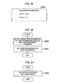
- Each of the controllers (S) 101 and (T) 111 holds logical volume information tables 300 and logical storage device information tables 310 as shown in Fig. 3 .
- the logical volume information table 300 is a table for associating a logical volume 104 formed on the self-side or corresponding storage system with logical storage devices 200.
- the table 300 exists for each logical volume 104.
- Each logical volume information table 300 is composed of a number 301 of each logical storage device 200 on which the corresponding logical volume 104 is mapped, a logical address range 308 indicating an address range on the logical volume mapped on the logical storage device 200, copy presence/absence information 302 indicating whether or not the logical storage device 200 includes a part of an area made an object of remote copying, a copy address range 305 indicating that portion of the area made the object of remote copying which the logical storage device 200 includes, emulation information 303 indicating the emulation type and capacity of the corresponding logical volume 104, original/copy information 304 indicating whether the corresponding logical volume is a copy source (original) or a copy destination (copy), a copy pointer 306, and a pair state 307.
- the table 300 is formed as a table having a plurality of entries with the logical storage device number 301, the logical address range 308, the copy presence/ absence information 302 and the copy address range 305 taken as one indexed entry. Then, a method of determining the address of the logical storage device 200 from the address of the logical volume 104 designated by the CPU 120 will be described using an example.
- a logical volume 104 has a capacity of 4n with addresses of 0 to 4n-1 applied and is mapped on logical storage devices 200 applied with numbers of 0 to 3 each having a capacity of n. Then, the logical storage device number 301 and the logical address range 308 in an entry having an index of 0 are stored with 0 and 0 to n-1, respectively, those in an entry having an index of 1 are stored with 1 and n to 2n-1, respectively, --- and so forth.
- which logical storage device 200 is a logical address designated from the CPU 120 included in can be determined by dividing the designated logical address by the capacity of the logical storage device 200. Namely, the quotient of the division indicates an entry in which an intended logical storage device number 301 is stored, and the remainder thereof indicates an address on the logical storage device 200.
- whether or not the logical address designated from the CPU 120 is included in the area made the object of remote copying can be determined by merely making the comparison with a copy address range 305 in the entry in which the intended logical storage device number 301 thus obtained is stored. Consequently, the introduction of the units of logical storage devices makes it possible to easily perform a processing on a remote copy area and makes it possible to reduce overhead as compared with the case where the units of logical storage devices are not introduced.
- the original/copy information 304 in the logical volume information table 300 indicates whether the corresponding logical volume is the logical volume (S) 104, that is, a copy source volume (original volume) or the logical volume (T) 114, that is, a copy destination volume (copy volume) in the case where the corresponding logical volume is a logical volume which forms a pair (hereinafter referred to as "remote copy pair") provided by a logical volume made an object subjected to remote copying and a logical volume of the destination of remote copying.
- the pair state 307 indicates which state is the remote copy pair placed in.
- the state of the pair includes a simplex state indicating that the corresponding logical volume is not a logical volume forming a remote copy pair, an under-copying state in which the copying from the logical volume (S) 104 to the logical volume (T) 114 is being performed, a duplex state in which an operation in a duplicated state is made, a suspended state in which the contents of the logical volume (S) 104 and those of the logical volume (T) 114 do not coincide with each other, and so forth.
- the copy pointer 306 indicates where is the copying for the remote pair forming logical volumes (S) 104 and (T) 114 or the copying from the former to the latter completed up to.
- the emulation information 303 is stored information of the logical volume (S) 104 in order to emulate a logical volume of a main frame.
- S logical volume
- the emulation information 303 (the emulation type and the capacity) of the logical volume information table 300 of the logical volume (T) 114 held by the controller (T) 111 is stored with the emulation information 303 (the emulation type and the capacity) in the logical volume information table 300 of the logical volume (S) 104 held by the controller (S) 101.
- the capacity of the logical volume (S) 104 is stored as the emulation information 303.
- the logical storage device information table 310 is a table for associating the logical storage device 200 with the storage devices 103. In the case where the corresponding logical storage device 200 is made an object subjected to remote copying, the table 300 associates the logical storage device 200 with the opposite-side logical volume 114. The table 310 exists for each logical storage device 200.
- Each logical storage device information table 310 held by the controller (S) 101 is composed of a storage device number 311 of each storage device (S) 103 on which the corresponding logical storage device (S) 200 is mapped, an address range 312 indicating an address range of the corresponding logical storage device (S) 200 mapped on the storage device (S) 103, RAID level information 313 indicating a RAID level assigned to a RAID group 205 formed by the storage devices (S) 103, and a pair controller number 314 and a pair logical volume number 315 for specifying, in the case where the corresponding logical storage device 200 includes a part of an area made an object of remote copying, the controller (T) 111 and the logical volume (T) 114 of the storage system (T) 110 which is a destination of remote copying.
- each logical storage device information table 310 held by the controller (T) 111 the storage device number 311 and the address range 312 are stored with a storage device number and an address range of each storage device (T) 113 on which the corresponding logical storage device (T) 210 is mapped. Also, the RAID level information 313 is stored with a RAID level assigned to the RAID group 215 formed by the storage devices (T) 113. Further, the pair controller number 314 in each logical storage device information table 310 held by the controller (T) 111 is stored with a controller number of the controller (S) 101 and the pair logical volume number 315 is stored with a null value.
- a logical address designated from the CPU 120 is converted into a number of a logical storage device 200 and an address on that logical storage device 200, as mentioned above. Which storage device 103 does this logical address actually correspond to is determined by a logical storage device information table 310 corresponding to the logical storage device number obtained by the conversion. If the access from the CPU 120 in this case is a write access, the reference to the RAID level information 313 of the logical storage device information table 310 is made to generate redundant data in accordance with the RAID level and the generated redundant data is also written into the storage device 103. For this method can be applied a method disclosed by, for example, D.A. Patterson, G. Gibson and R.H.
- the controller number 314 and the logical volume number 315 of a destination of remote copying are examined from the logical storage device information table 310 corresponding to the corresponding logical storage device (S) 200 to make access to an intended logical volume (T) 114 through the inter-controller path 160.
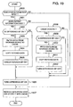
- This operation includes three processings, that is, a processing for generation of a remote copy pair, a processing at the time of writing from the CPU 120 to the storage system (S) 100, and a processing for operation switching from the storage system (S) 100 to the storage system (T) 110. In the following, each of these processings will be described.
- Fig. 4 shows the flow of the remote copy pair generation processing.
- a logical volume 104 made an object subjected to remote copying and an area made an object of remote copying are designated at the primary site, as shown.
- the designation is made by a user to the controller (S) 101 from the exterior of the storage system (S) 100, for example, the CPU (S) 120, an external terminal (hereinafter referred to as "SVP: service processor" connected to the controller (S) 101, or the like.
- SVP service processor
- the controller (S) 101 When the designation of a number of the logical volume 104 made the object subjected to remote copying and the area made the object of remote copying is made to the controller (S) 101, the controller (S) 101 operates in the above-mentioned method so that the definition as "COPY SOURCE" is made into the original/copy information 304 of a logical volume information table 300 corresponding to the designated number of the logical volume 104 and addresses defined by the remote copy area are stored into the copy address range 305. Thereafter or in step 401, a request for remote copy pair generation accompanied with parameters including at least an emulation type, the capacity of the corresponding logical volume 104 and the area made the object of remote copying is issued from the controller (S) 101 to the controller (T) 111. Regarding the value of each parameter, the emulation type and the capacity of the corresponding logical volume 104 are determined from the emulation information 303 and a remote copy address area is determined by referring to the copy address range 305.
- the controller (T) 111 assigns a logical volume (T) (step 410). More especially, an unused logical volume (T) 114 is first ensured. This logical volume may be ensured in such a manner that an unused logical volume is designated from the exterior or the controller (T) 111 assigns any unused logical volume. Next, unused logical storage devices (T) 210 are assigned to the logical volume (T) 114 so that the area designated by the controller (S) 101 as the object of remote copying is involved in terms of the capacity. Further, the definition as "COPY DESTINATION" is made into the original/copy information 304 of a logical volume information table 300 corresponding to the logical volume (T) 114.
- a number of each logical storage device (T) 120 assigned to the logical volume (T) 114 is stored into the logical storage device numbers 301 of the logical volume information table 300 corresponding to the earlier assigned logical volume (T) 114.
- "COPY PRESENT" is stored into the copy presence/absence information 302 of the logical volume information table 300.
- the logical address range received from the controller (S) 101 as including the area made the object of remote copying is mapped on each assigned logical storage device (T) 210.
- the mapped logical addresses are stored into the logical address range 308 of the logical volume information table 300 in an entry corresponding to that logical storage device (T) 210.
- the copy address range 305 of the logical volume information table 300 in an entry corresponding to each assigned logical storage device (T) 210 is stored with that address range of the area made the object of remote copying which is included in the logical address range mapped on that logical storage device (T) 210.
- addresses n to 4n-1 of the logical volume (S) 104 are the area made the object of remote copying and two logical storage devices numbered by i and j each having a capacity of 2n are assigned to the logical volume (T) so that addresses n to 3n-1 are mapped on the i-numbered logical storage device (T) 210 and addresses 3n to 5n-1 are mapped on the j-numbered logical storage device (T) 210.
- the range of n to 3n-1 is stored into both the logical address range 308 and the copy address range 305 in an entry of the logical volume information table 300 indexed with 0 and having the logical storage device number 301 of i
- the range of 3n to 5n-1 and the range of 3n to 4n-1 are respectively stored into the logical address range 308 and the copy address range 305 in an entry indexed with 1 and having the logical storage device number 301 of j.
- the assignment is made, for example, as shown in Figs. 2A and 2B .
- two meshed logical storage devices (T) 211 and 212 are assigned to a logical volume (T) 114 formed for that area made an object of remote copying on which two logical storage devices (S) 201 and 202 are mapped.
- the logical storage devices (T) 210 may be placed at physically distanced positions on the storage devices (T) 113.
- the logical storage devices (T) 210 may be positioned on separate RAID groups (T) 215.
- the controller (T) 111 stores the emulation type and the capacity received from the controller (S) 101 into the emulation information 303 of the logical volume information table 300 of the logical volume (T) 114.
- the controller (T) 111 informs the controller (S) 101 of the completion of the processing.
- the controller (S) 101 informed by the controller (T) 111 of the processing completion operates so that a number of the logical volume (T) 114 assigned by the controller (T) 111 is stored into the pair logical volume number 315 of a logical storage device information table 310 corresponding to a logical storage device 200 including a part of the area made the object of remote copying.
- the number of the logical volume (T) 114 may be given by the user to the controller (S) 101 from the exterior. Otherwise, when the controller (T) 111 gives the information of processing completion, the controller (T) 111 may inform the controller (S) 101 of the number of the logical volume (T) 114 at the same time.
- the controller (S) 101 operates so that the area on the logical volume (S) 104 made the object of remote copying is copied into the logical volume (T) 114 with the pair state 307 of the logical volume information table 300 of the logical volume (S) 104 turned into an under-copying state (step 402). Namely, in accordance with the value of the copy pointer 306, an uncopied region in the area made the object of remote copying is transferred to the controller (T) 111 of the storage system (T) 110 with a logical address of that region taken as a destination of transfer.
- the controller (T) 111 stores each data into a storage device (T) 113 on which a logical storage device (T) 210 mapped with the logical address of the destination of transfer is mapped. As the copying proceeds, the copy pointer 306 is updated. At a point of time when the copying of the area made of remote copying is completed, the pair state 307 of the logical volume information table 300 of the logical volume (S) 104 is turned into a duplex state.
- logical storage devices (T) 210 cannot be assigned on storage devices (T) 113 notwithstanding that a request for remote copy pair generation is made from the controller (S) 101.
- the controller (T) 111 informs the controller (S) 101 that it is impossible to generate a copy.
- the designation of an area made an object of remote copying is given to only the controller (S) 101 and the controller (T) 111 is then informed by the controller (S) 101.
- the user can designate the area made the object of remote copying not only to the controller (S) 101 but also to the controller (T) 111.
- the controller (T) 111 makes the assignment of a logical volume 114 by means of the above-mentioned method.
- the user may designate a number of an unused logical volume (T) 114 in the storage system (T) 110 to both the controller (S) 101 and the controller (T) 111.
- the user is enabled to make the designation as to whether only a capacity corresponding to the minimum logical storage devices (T) 210 required for the area designated from the controller (S) 101 as the object of remote copying should be ensured as the capacity of the logical volume (T) 114 or a capacity equivalent to the logical volume (S) 104 should be ensured as the capacity of the logical volume (T) 114, and the controller (T) 111 ensures the capacity of the logical volume (T) 114 in accordance with the user's designation.
- This user's designation may be made to the controller (S) 101 so that the controller (T) 111 is then informed by the controller (S). Otherwise, the designation may be made to the controller (T) 111 directly.
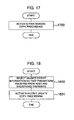
- a write processing will be described. This processing is performed at the time of writing from the CPU 120 into the storage system (S) 100.
- Fig. 5 shows the flow of the write processing.
- the controller (S) 101 When receiving a request for writing from the CPU 120 to the storage system (S) 100 (step 500), the controller (S) 101 writes the write data transferred from the CPU (S) 120 into the cache memory of the controller (S) 101 (step 501). Thereafter, the reference to the logical volume information table 300 and the logical storage device information table 310 is made so that the write data is written into a storage device (S) 103 corresponding to a logical address.
- step 502 if the write request received from the CPU (S) 102 is one for a logical volume for which the definition as "COPY SOURCE" is made as the original/copy information 304 of the logical volume information table 300, the judgement is made of whether or not this write request is the writing to an area made an object of remote copying. More particularly, a number of a logical storage device including an area to be accessed is further determined from the logical volume information table 300 so that the examination based on the copy presence/absence information 302 of the logical volume information table 300 is made as to whether or not the corresponding logical storage device (S) 200 includes a part of the area made the object of remote copying.
- the examination based on the copy address range 305 is made as to whether or not the area accessed by the CPU (S) 120 is included in the area made the object of remote copying. If the area accessed by the CPU (S) 120 is included in the area made the object of remote copying, the write data is transferred to the controller (T) 111 through the inter-controller path 160 on the basis of a predetermined protocol (step 503). Namely, the writing from the controller (S) 101 is made for a logical volume (T) 114 defined by the controller (T) 111.
- a controller device number and a logical volume number of the destination of writing are recorded in the logical storage device information table 310 of the controller (S) 101. Since an actual example of the predetermined protocol includes, for example, a CKD protocol in the case of a main frame and a fiber channel protocol in the case of an open system, these protocols are used.
- An address for writing from the controller (S) 101 to the controller (T) 111 is the same as an address for writing from the CPU 120 to the logical volume (S) 104.
- the controller (T) 111 informs the controller (S) 101 of the completion of writing (step 511) at a point of time when the write data received from the controller (S) 101 is stored into the cache (step 510). Thereafter, the reference is made to the logical volume information table 300 and the logical storage device information table 310 to perform the writing to a storage device (T) 113 which corresponds to a logical address.
- the controller (S) 101 informed by the controller (T) 111 of the writing completion informs the CPU 120 of the completion of writing (step 504), thereby completing the write processing. Such a writing processing is also performed when a copy pair is being generated.
- step 502 whether or not an area made the object of access has already been subjected to copying is judged from the copy presence/ absence information 302 and the copy pointer 306 and write data is transferred to the controller (T) 111 when the area has already been subjected to copying. Also, in the case where the write request from the CPU 120 is the writing to an area other than the area made the object of remote copying (step 502), the flow goes to step 504 in which the CPU 120 is informed of the completion of writing, thereby completing the write processing.
- This processing is performed in the case where the storage system (S) 100 becomes impossible of use due to a disaster or the like.
- a CPU 140 is first connected to the storage system (T) 110. If possible, the CPU (S) 120 having been connected in the storage system (S) 100 is used as the CPU 140 to be connected. If the connection of the CPU (S) 120 is impossible and a CPU (T) 140 has already existed, this CPU (T) 140 can be used. Also, if necessary, a new CPU (T) 140 may be installed and connected.
- the contents of the logical volume information table 300 of the logical volume (S) 114 stored in the controller (T) 111 are first obtained in step 601, as shown in Fig. 6 . More particularly, the contents of the logical volume information table 300 are read from the CPU (T) 140 or read from an SVP or the like connected to the controller (T) 111.
- the contents of the logical volume information table 300 include the capacity of the logical volume (T) 114, the capacity of the logical volume (S) 104, the remote copy address range, the emulation type, and so forth.
- the logical volume (T) 114 has only a copy of a partial area of the logical volume (S) 104. Therefore, it is required that the logical volume (T) should be turned into a physically and logically noncontradictory condition and into a usable condition on the basis of the read logical volume information table 300 of the logical volume (T) 114.
- the capacity of the logical volume (T) 114 is made equal to the capacity of the logical volume (S) 104.
- dataset and file management information such as VTOC or i-node information is operated to erase dataset and file management information which does not exist in the logical volume (T) 114.
- This processing is required only when there is a difference between the capacity of the logical volume (S) 104 and the capacity of the logical volume (T) 114. Also, this processing is performed in response to a user's request.
- the controller (T) 111 first obtains a difference between the capacity of the logical volume (S) and the capacity of the logical volume (T). More particularly, the emulation type and the capacity of the logical volume (S) 104 are acquired from the logical volume information table 300 of the logical volume (T) 114. Further, on the basis of the logical volume information table 300 of the logical volume (T) 114, the capacity of the logical volume (T) 114 is obtained from the number and the capacity of logical storage devices 210 which are assigned to the logical volume (T) 114.
- the CPU (T) 140 or the SVP instructs the controller (T) 111 to assign logical storage devices 210 having a capacity corresponding to the difference in capacity.
- the instructed controller (T) 111 searches for logical storage devices 210 in unused states to assign logical storage devices 210 which correspond to the designated capacity.
- a track format of the assigned logical storage device 210 must be conformable to the emulation type.
- the unused logical storage device 210 should be formatted beforehand. Also, in the case where no unused logical storage device 210 exists, it is necessary to cope with this, for example, by additionally installing storage devices 113.
- logical addresses having existed on the logical volume (S) 104 are assigned to those newly assigned logical storage devices 210. More particularly, an address range excepting an address range having already been assigned (that is, an address range in an area made an object of remote copying) is mapped in order.
- two logical storage devices 210 are newly assigned (with their logical storage device numbers set to i and j) so that logical addresses 0 to 2n-1 are assigned to the i-numbered logical storage device 210 and logical addresses 3n to 4n-1 are assigned to the j-numbered logical storage device 210.
- the number and the logical address range of the newly assigned logical storage 210 are stored into the logical storage device number 301 and the copy address range 305 of the logical volume information table 300.
- logical storage devices (T) 210 corresponding to a value obtained by subtracting the total of the capacities of all logical volumes (T) 114 from the capacity of the logical volume (S) 104 are newly assigned to one logical volume (T) 114 and there are applied logical addresses which are not mapped on all the logical volumes (T) 114 but have already existed on the logical volume (S) 104.
- one logical volume (T) 114 is formed by an assembly of the logical storage devices (T) 210 assigned to all the logical volumes (T) 114 and is assigned with a logical volume number.
- the logical volume number to be assigned may be one of logical volume numbers hitherto used for the logical volumes (T) 114 or may be given by the user from the exterior.
- the user changes file management information (step 603). This is performed for making dataset and file management information logically noncontradictory.
- the file management information includes logical volume numbers, the names of datasets and files stored, addresses on logical volumes, and so forth.
- the change of the file management information is made by erasing that one of information of datasets and files stored in the file management information which is not included in the area made the object of copying (or which is included in an area other than the area made the object of copying), thereby making a change in definition so that the other area is rendered into an unused area.
- addresses outside of the area made the object of remote copying are first determined on the basis of the copy address range 305 of the logical volume information table 300 held in the controller (T) 111.
- the file management information is searched for datasets and files included in an area other than the area made the object of remote copying. If such datasets and files exist, management information thereof is erased so that the other area is rendered into an unused area, thereby updating the file management information.
- the CPU 140 is caused to execute a utility program having the above-mentioned function.
- the service at the secondary site is restarted in step 604.
- the storage system 1000 serving as a copy destination has a controller 1010 and storage devices 1030
- the storage system 1100 serving as a copy source has a controller 1110 and storage devices 1130.
- the storage system 1100 serving as the copy source and the constituent elements thereof will be denoted with (S) and the storage system 1000 serving as the copy destination and the constituent elements thereof will be denoted with (T).
- a CPU 1200 is placed in a state connected to the storage system (S) 1100, that is, the storage system which serves as the data migrating copy source.
- the new storage system (T) 1000 is carried therein and the connection path from the CPU 1200 to the storage system (S) 1100 is changed so that the connection to the storage system (T) 1000 is effected.
- the controller (T) 1010 and the controller (S) 1110 are connected by an inter-controller path 1600. This state is shown in Fig. 7 .
- the storage system (T) 1000 is a storage system in which the controller (T) 1010 manages a logical volume (T) 104 by means of logical storage devices 200 described and shown in conjunction with the first embodiment and holds logical volume information tables 300 and logical storage device information tables 310 (see Fig. 3 ) therein.
- the controller (S) 1110 of the storage system (S) 1100 is not required to hold those tables. Accordingly, the storage system serving as the copy source may be the conventional storage system.
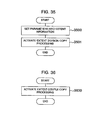
- Fig. 8 shows the flow of a processing for migratory copying.
- step 701 the controller (T) 1010 assigns the logical volume (T) 104 in accordance with the user's instruction.
- logical storage devices 200 in unused states are assigned to provide a capacity equal to or larger than the designated logical volume capacity and the storage device numbers thereof are stored into the logical storage device numbers 301 of the logical volume information table 300 in accordance with the order of assignment.
- the designated emulation type and capacity are stored into the emulation information 303, thereby completing the assignment of the logical volume (T) 104.
- the user can designate the capacity of the logical volume (T) 104. Accordingly, it is possible to form a logical volume (T) 104 of any capacity which includes an area made an object of copying.
- the user changes file management information of a logical volume (S) 114 of the copy source (step 702). More particularly, the file management information is searched for datasets and files included in an area other than the area made the object of migratory copying so that management information of the searched-out datasets and files is erased.
- step 703 the logical volume (S) 114 of the copy source is brought into an off-line condition disconnected from the CPU 1200 so that it cannot be accessed.
- step 704 the controller (T) 1010 is instructed to perform migratory copying with at least a controller number and a logical volume number of the copy source, a logical volume number of the destination of migratory copying and an area of the object of migratory copying taken as parameters.
- the controller (T) 1010 When receiving the instruction for the start of migratory copying, the controller (T) 1010 starts the migratory copying from the designated area of the designated logical volume (S) 114 of the storage system (S) 1100 (step 711).
- the copy pointer 306 of the logical volume information table 300 Prior to the migratory copying, the copy pointer 306 of the logical volume information table 300 is first initialized, that is, a leading address of the area made the object of migratory copying is stored into the copy pointer 306.
- "MIGRATORY COPY PRESENT" is stored into the copy presence/absence information 302 for a logical storage device 200 including a part of the area made the object of migratory copying.
- the copy address range 305 is stored with those logical addresses of the area of the object of migratory copying which are included in a logical address range mapped on the corresponding logical storage device 200. For example, provided that logical addresses m (0 ⁇ m ⁇ k-1) to n (k-1 ⁇ n) are designated for the area made the object of migratory copying, the logical addresses m to k-1 are stored into the copy address range 305 of a logical storage device (T) 200 on which the logical addresses 0 to k-1 are mapped. Subsequently, the pair state 307 of the logical volume information table 300 is turned into an under-migratory-copying state. And, the designated controller number and logical volume number are stored into the pair controller number 314 and the pair logical volume number 315 of the logical storage device information table 310.
- the controller (T) 1010 starts the copying of the area made the object of migratory copying.
- the controller (T) 1010 reads data from a predetermined region of the logical volume (S) 114 in an order from the lead of the designated area in accordance with the value of the copy pointer and writes the data into a storage device (T) 1030 which forms a logical storage device (T) 200 corresponding to the read logical address.
- the copy presence/absence information 302 in the logical volume information table 300 corresponding to the copy-completed logical storage device (T) 200 is turned into "COPY ABSENT".
- the pair state is turned into a simplex state, thereby completing the migratory copying.
- the user brings the data migratory copy destination logical volume (T) 104 of the storage system (T) 1000 into an on-line condition for the CPU 1200 to restart the service (step 705).
- the CPU 1200 is enabled to issue an input/output request to the storage system (T) 1000.
- the controller (T) 1010 uses the copy presence/absence information 302, the copy address range 302, the pair state 307 and the copy pointer 306 to examine whether or not an access address from the CPU 1200 falls in an area having not yet been subjected to copying. If the case is so, the controller (T) 1010 reads the corresponding data from the storage system (S) 1100 to store it into a cache memory of the controller (T) 1010 and copes with the access from the CPU 1200 by use of the stored data.
- a logical volume is distributively arranged/rearranged on a plurality of RAID groups.
- Fig. 9 shows the construction of a storage system according to the third embodiment.
- a storage system 1001 has a controller 1011 and a plurality of storage devices 1031 which form a plurality of RAID groups 205.
- the storage system 1001 is connected to a CPU 1201.
- the storage system 1001 is a storage system in which the controller 1011 manages a logical volume 104 by means of logical storage devices 200 described and shown in conjunction with the first embodiment and holds logical volume information tables 300 and logical storage device information tables 310 (see Fig. 3 ) therein.
- the logical storage devices 200 are obtained by dividing, for each of the RAID groups 205, the address space of that RAID group by every fixed length. Accordingly, one logical storage device 200 is sure to be a part of the address space of one RAID group 205 and never extends over the address spaces of plural RAID groups 205.
- a logical storage device 200 forming a logical volume 104 is selected from any RAID group 205, thereby making it possible to arrange a logical volume on any RAID group by every any area of the volume. The details will now be described.
- a user designates at least a logical volume number, an area of the logical volume 104 and a number of a RAID group 205 in which that area is to be stored.
- the user's designation is given to the controller 1011.
- the controller 1011 assigns unused logical storage devices 200 from the designated RAID group 205 to provide a capacity equal to or larger than the capacity of the designated area and maps a logical address range inclusive of the designated area onto the assigned logical storage devices 200. If the unused logical storage devices 200 do not exist, the controller 1011 informs the user that the assignment is impossible.
- Numbers of the assigned logical storage devices 200 are stored into the logical storage device numbers 301 of the logical volume information table 300 in accordance with the order of assignment. Thereafter, the controller 1011 informs the user of the logical address range mapped on the assigned logical storage devices 200. Thereby, the user is enabled to designate the next area in reference to the notified logical address range so that the overlapping of areas is not generated.
- the logical volume 104 If the logical volume 104 has already been operating so that valid data is stored in the designated area, it is necessary to rearrange logical storage devices 200 in which the valid data is stored. For this rearrangement, it is necessary that not only the mapping of logical addresses of logical storage devices 200 is changed but also data from logical storage devices having valid data therein is copied into newly assigned logical storage devices 200. Namely, in the case where the logical volume 104 has already hold valid data, there exists the corresponding logical volume table 300.
- the controller 1011 stores a number of the copy destination logical storage device 200 into the pair logical volume number 315 of a logical storage device information table 310 of a copy source logical storage device 200 and records "COPY PRESENT" into the copy presence/absence information 302 for the copy source logical storage device 200 in the logical volume information table 300. This operation is performed for all of the copy destination logical storage devices 200.
- the copy pointer 306 is initialized or set to address 0 so as to start the copying from the leading address of a leading copy source logical storage device 200 and the pair state 307 is turned into an under-copying state to start the copying.
- the copy source logical storage device number 301 registered in the logical volume information table 300 is rewritten to a copy destination logical storage device number stored in the pair logical volume number 315 of the logical storage device information table 310 of the copy source logical storage device 200 and the copy presence/absence information 302 in an entry having this logical storage device number is turned into "COPY ABSENT".
- "COPY PRESENT" is set as the copy presence/absence information 302 in a logical volume information table 300 for a logical storage device 200 on which a write area is mapped in the logical volume information table 300. In this case, it is necessary to write the write data into a copy destination logical storage device 200 as follows.
- the examination based on the logical volume information table 300, more especially, the copy presence/absence information 302 for the logical storage device 200 having the write area mapped thereon and the copy pointer 306 is made as to whether the write area is an area having already been subjected to copying, an area having not yet been subjected to copying or an area other than an area made an object of copying. If the write area is an area having already been subjected to copying, the data is written into a copy destination logical storage device 200 indicated by a copy destination logical storage device number stored in the pair logical volume number 315 of a logical storage device information table 310 for the logical storage device 200 on which the write area is mapped. If the write area is an area having not yet been subjected to copying or an area other than an area made an object of copying, the write data is written into the logical storage device 200 on which the write area is mapped.
- data is read from a copy destination logical storage device 200 if a read area or an area to be subjected to reading is an area having already been subjected to copying and from a copy source logical storage device 200 if the read area is an area having not yet been subjected to copying or an area other than an area made an object of copying. While a input/output request from the CPU 1201 is thus processed, the copying is performed. When the copying is completed for the entire area, the pair state is turned into a simplex state (or a copy pair absent state), thereby completing the reconstruction of the logical volume 104.
- a logical volume 104 has been rearranged in accordance with the user's designation of a logical volume number, an area of the logical volume 104 and a number of a RAID group 205 in which that area is to be stored.
- an access pattern and statistical information such as operation information are acquired for each logical storage device 200 so that a logical volume 104 is rearranged automatically or manually by virtue of the characteristic of the acquired information.
- the read rate and write rate of a random access, the read rate and write rate of a sequential access, the utilization rate of a logical storage device 200, and so forth are acquired for each logical storage device 200.
- Such statistical information is examined at a certain fixed period to calculate the optimum arrangement of logical storage devices 200.
- An example of a method for determining the optimum arrangement includes determining the utilization rate of each RAID group 205 from the sum of the utilization rates of logical storage devices 200 which form that RAID group 205. If the utilization rates of the respective RAID groups 205 have a large dispersion or difference, the logical storage devices 200 are rearranged on the RAID groups 205 so that the utilization rates are leveled.
- the arrangement is determined taking an access pattern into consideration additionally. For example, in the case where a random access is frequently made, the shortening of a response time becomes important. Therefore, a logical storage device subjected to such access is arranged on a RAID group which is formed by high-speed, small-capacity storage devices and has a RAID level of RAID 1. In the case where a sequential access is frequently made, a throughput (or the number of I/O processings per unit time) becomes important. Therefore, a logical storage device subjected to such access is arranged on a RAID group which has a RAID level of RAID 5. With such arrangement, many storage devices are simultaneously operated to improve the throughput.
- a processing for determination of the rearrangement mentioned above may be performed by a processor provided in the controller 101 or an external terminal connected to the controller 101.
- the copying is performed in a manner similar to that in the third embodiment so that the arrangement of logical storage devices 200 are actually changed.
- a memory area for ensuring logical storage device information tables 310 is required to be larger as the capacity of the logical storage device 200 is made smaller. This deteriorates the efficiency in the case where only a part of the logical volume 104 is made an object of remote copying.
- the construction of an information system according to the fifth embodiment is similar to that shown in Fig. 1 .
- the fifth embodiment is different in that the controller (S) 101 and the controller (T) 111 are provided with tables shown in Figs. 10 and 11 in lieu of the logical volume and logical storage device information tables 300 and 310 shown in Fig. 3 .
- the details will now be described.
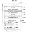
- the controller (S) 101 holds logical volume information tables 800, RAID group management tables 840, group tables 820 and pair management tables 830 as shown in Fig. 10 .
- the logical volume information table 800 and the group table 820 are provided for each logical volume.
- the RAID group management table 840 is provided for each RAID group.
- the area of the logical volume 104 is divided into groups by every equal size and these groups are sequentially numbered.
- the grouping is made in terms of the number of blocks in the case of an open system and in terms of the number of cylinders or the number of tracks in the case of a main frame, and the groups are numbered with 0, 1, --- in a sequence from a group including a leading address.
- the logical volume information table 800 is composed of a RAID group number 801 indicating a number of a RAID group 205 forming a logical volume 104, an address range 802 indicating an address range of the logical volume on the RAID group 205, emulation information 803, original/ copy information 804, and a group table number 805.
- the address range on the RAID group 205 is an address range on storage devices 103 forming the RAID group 205, that is, a leading address and the number of blocks.
- An area indicated by this address range forms a logical volume 104.
- one logical volume 104 is defined by a common address range of storage devices 103 forming a RAID group, a leading address of this common address range and the number of blocks therein are stored into the address range 802.
- the emulation information 803 and the original/ copy information 804 are the same as the emulation information 303 and the original/copy information 304 (see Fig. 3 ) shown in conjunction with the first embodiment. If the corresponding logical volume 104 is made an object of copying, "COPY SOURCE" is stored into the original/copy information 804. On that particular case, the value of the group table number 805 becomes valid.
- the group table number 805 is stored with a number of a group table 820 assigned to the logical volume.
- the RAID group management table 840 is a table for associating a RAID group 205 with storage devices 103.
- the table 840 is composed of storage device numbers 841 stored with numbers of storage devices 103 forming a RAID group 205, a RAID level 842 stored with the RAID level of the RAID group, and an idle address range 843 representing an unused area of the RAID group 205.
- the group table 820 is a table by which each of groups of a logical volume 104 assigned with that group table 820 is associated with a pair management table 830 managing a copy destination logical volume 114 of that group.
- the table 820 stores a pair management table number 821 associated with each group. By making access to the group table 820 with a group number taken as an index, it is possible to know a pair management table number of the corresponding group.
- the pair management table 830 is a table for associating a copy source logical volume 104 with a copy destination logical volume 114.
- the table 830 is composed of an opposite-side controller number 831 stored with a number of a copy destination controller (T) 111, an opposite-side logical volume number 832 stored with a number of a logical volume (T) 114 of a copy destination storage system (T) 110, a self-side logical volume number 833 stored with a number of a copy source logical volume (S) 104, a copy source leading address 834 and a copy source tailing address 835 stored with leading and tailing addresses of the logical volume (S) 104 which are made an object of copying, a pair state 836 indicating the state of a copy pair, and a copy pointer 837 representing the progression of the copying.
- the group tables 820 and the pair management tables 830 are held by a number defined in the system beforehand, and the number is determined a memory capacity of the controller (S) 101 and the maximum number of pairs. Also, these tables are dynamically assigned and opened, as required. Namely, when a pair is generated, an unused table is assigned. When the pair is released, the table is opened or turned into an unused condition again. Accordingly, there is no fear that a large-capacity storage resource is consumed for storing the group tables 820 and the pair management tables 830.
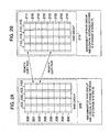
- the controller (T) 111 holds logical volume information tables 900 shown in Fig. 11 and the RAID group management tables 840 shown in Fig. 10 .
- the logical volume information table 900 is provided for each logical volume (T) 114.
- the table 900 is composed of a copy source controller number 905 stored with a number of a controller (S) 110 as a copy source of the logical volume (T) 114, a copy source logical volume number 906 stored with a number of a logical volume (S) 104 of a copy source storage system (S) 100, and a copy address range 907 stored with an address range of the copy source logical volume (S) 104 made an object of copying.
- the table 900 further holds a RAID group number 901, an address range 902, emulation information 903, and original/copy information 904, the contents thereof are similar to those shown in Fig. 10 .
- this operation includes three processings, that is, a processing for generation of a remote copy pair, a processing at the time of writing from the CPU 120 to the storage system (S) 100, and a processing for operation switching from the storage system (S) 100 to the storage system (T) 110.
- a processing for generation of a remote copy pair a processing at the time of writing from the CPU 120 to the storage system (S) 100
- a processing for operation switching from the storage system (S) 100 to the storage system (T) 110 a processing for operation switching from the storage system (S) 100 to the storage system (T) 110.
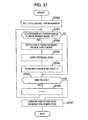
- step 400 of Fig. 4 a user gives an instruction for remote copy pair generation to the controller (S) 101 together with information similar to that in the first embodiment.
- the controller (S) 101 When receiving the instruction for remote copy pair generation in step 400, the controller (S) 101 assigns one unused pair management table 830. If there is no unused pair management table 830, it is impossible to newly generate a copy pair and hence the controller (S) 101 informs the user of that effect, thereby completing the processing. In this case, it is necessary for the user to release a copy pair having already been generated, thereby opening a pair management table 830.
- a number of a copy destination controller (T) 111 given from the user is stored into the opposite-side controller number 831 of the pair management table 830 and a number of a copy source logical volume (S) 104 is stored into the self-side logical volume number 833 thereof. Also, a copy leading (head) address and a copy tailing (end) address given from the user are stored into the copy source leading address 834 and the copy source tailing address 835 of the pair management table 830, respectively.
- an unused group table 820 is assigned to this logical volume.
- a number of the now assigned pair management table 830 is stored into an entry corresponding to a group including a portion of an area made an object of remote copying and a null value is stored into an entry corresponding to a group in an area other than the area made the object of remote copying. Since each group has a fixed length, logical addresses corresponding to each group are uniquely defined by a group number.
- a number of the now assigned group table 820 is stored into the group table number 805 of a logical volume information table 800 corresponding to the logical volume instructed for remote copy pair generation and "COPY SOURCE" is stored into the original/copy information 804 thereof.
- step 401 a request for remote copy pair generation is issued to the controller (T) 111.
- Parameters transferred to the controller (T) 111 together with the request for remote copy pair generation are similar to those in the first embodiment.
- the controller (T) 111 assigns an unused logical volume 114 as a logical volume (T) 114 (step 410).
- a capacity conformable to the area designated from the controller (S) 101 as the object of remote copying is assigned to the logical volume (T) 114, as follows. Namely, the controller (T) 111 refers to the idle address ranges 843 of RAID group management tables 840 to judge whether or not the required capacity can be ensured from a certain RAID group (T) 215. If the insurance is possible, the required capacity is ensured from an idle area and the idle address range is correspondingly updated.
- An unused logical volume information table 900 is assigned so that a number of the RAID group 215 and the address range as ensured are stored into the RAID group number 901 and the address range 902. If the idle address range 843 corresponding to the required capacity does not exist, a search is made for an assignable RAID group (T) 215 and the table 900 is assigned to the RAID group. Otherwise, the user may designate an assignable RAID group 215 beforehand.
- an emulation type and the capacity of the copy source logical volume (S) 104 received from the controller (S) 101 are stored into the emulation information 903 of the logical volume information table 900 corresponding to the assigned logical volume (T) 114, and "COPY DESTINATION" is stored into the original/copy information 904.
- a number of the copy source controller (S) 101 and a number of the copy source logical volume (S) 104 are stored into the copy source controller number 905 and the copy source logical volume number 906 of the logical volume information table 900, respectively.
- an address range of the area made the object of remote copying is stored into the copy address range 907.
- step 411 the controller (T) 111 informs the controller (S) 101 of a number of the assigned logical volume (T) 114.
- step 402 the controller (S) 101 stores the number of the logical volume (T) 114 received from the controller (T) 111 into the opposite-side logical volume number 832 of the pair management table 830, turns the pair state 836 into an under-copying state and stores the value of the copy leading address 834 into the copy pointer 837 to start a copy processing.
- the copy processing is performed in a manner similar to that in the first embodiment while updating the copy pointer 837.
- a group table 820 corresponding to the corresponding logical volume 104 has already been ensured and hence only a pair management table 830 is newly assigned to store information mentioned above. Also, a number of the newly assigned pair management table 830 is stored into an entry in the group table 820 corresponding to the group number of a group including the newly designated area portion of the object of remote copying. The subsequent processing is similar to that described until now.
- the difference of the present embodiment from the first embodiment with respect to a write processing lies in a method of judging whether or not an area made an object of writing falls in a copy range.
- the original/copy information 804 of a logical volume information table 800 corresponding to a logical volume (S) 104 made an object of access is looked at to examine whether or not the logical volume (S) 104 forms a remote copy pair as "COPY SOURCE". If it forms a remote copy pair as "COPY SOURCE", the group table number 805 is looked at so that a group number including addresses to be accessed is used as an index to access a group table 820. Then, a number of a pair management table 830 is known.
- the pair management table 830 indicated by this number is accessed.
- the judgement of whether or not a pair state is an under-copying state is made from the pair state 836.
- the pair state is an under-copying state
- the examination of whether or not the addresses to be accessed are included in an area having already been subjected to copying is made from the values of the copy leading address 834 and the copy pointer 837. If the addresses are included in that area, write data is transferred to the storage system (T) 110 and is then written.
- the judgement based on the copy leading address 834 and the copy tailing address 835 is made as to whether or not the addresses to be accessed are included in this range. If the addresses are included in that range, the write data is transferred to the storage system (T) 110 and is then written.
- a CPU 140 is first connected to the storage system (T) 110.
- a logical volume (S) 104 is held by a logical volume (T) 114. Therefore, if necessary, the logical volume (T) 114 is extended in terms of capacity so that it is conformable to the capacity of the logical volume (S) 104.
- a logical volume satisfying a required capacity is newly assigned to the storage system (T) 110 and data of the remote copy destination logical storage volume (T) 114 is copied into the newly assigned logical volume.
- the remote copy destination logical storage volume (T) 114 will be denoted by a logical volume A 114 and the newly assigned logical volume 114 will be denoted by a logical volume B 114.
- a user first reads capacity information of the logical volume A 114 from the CPU 140 or an external terminal connected to the controller (T) 111 (step 1001). Next, the judgement is made of whether the logical volume A 114 should be used as it is or the logical volume A 114 should be used in a form extended in terms of capacity so that it corresponds to the logical volume (S) 104.
- the emulation information 903 of a logical volume information table 900 corresponding to the logical volume A 114 is read to acquire the emulation type and capacity of the logical volume (S) 104 and the user instructs the controller (T) 111 on the basis of the acquired information to newly assign a logical volume B 114.
- the user designates at least the emulation type. Further, the user designates a logical volume number, as required.
- step 1010 the controller (T) 111 assigns the logical volume B 114 of the designated emulation type and capacity.
- the assignment of the new logical volume B 114 is not necessarily required.
- a logical volume 114 defined on the storage system 110 of the secondary site may be used.
- step 1003 the user makes an instruction for the copying of data from the logical volume A 114 into the logical volume B 114.
- the user looks at the copy address range 907 of the read logical volume information table 900 to designate an area to be copied.
- the controller (T) 111 copies data of the designated area from the logical volume A 114 into the logical volume B 114. Since addresses on the remote copy source logical volume (S) 104 are stored in the copy address range 907, the copying is performed for an area of the logical volume B 114 corresponding to these addresses. For example, provided that addresses m to n are stored in the copy address range 907, data of the logical volume A 114 is copied into an area of the logical volume B 114 corresponding to addresses m to n.
- file management information is updated in a manner similar to that in the first embodiment (step 1004) and the operation at the secondary site is thereafter started (step 1005).
- the file management information is updated and the operation at the secondary site is then started.
- the updating of the file management information and the subsequent start of the operation may be possible in the midst of copying. This can be realized by making access to the logical volume A 114 if the logical volume A 114 has already been subjected to copying and access to the logical volume B 114 if the logical volume A 114 has not yet been subjected to copying.
- the storage system (T) 1000 shown in Fig. 7 is different from that in the second embodiment, that is, the controller (T) 1010 holds the logical volume information tables 800, the RAID group management tables 840, the group tables 820 and the pair management tables 830 (see Fig. 10 ) described in conjunction with the fifth embodiment and performs a processing by use of these tables.
- a user designates at least an emulation type and a capacity to be assigned.
- the controller (T) 1010 instructed to assign the logical volume (T) 104 assigns the logical volume (T) 104 in a manner similar to the assignment of the logical volume B 114 in the fifth embodiment.
- the user may designate a logical volume 104 having already been defined on the storage system (T) 1000.
- step 711 the controller (T) 1010 receiving the instruction for the start of migratory copying assigns an unused pair management table 830, stores a number of the migratory copy source controller (S) 1110 and a number of a migratory copy source logical volume (S) 114 into the opposite-side controller number 831 and the opposite-side logical volume number 833 of the pair management table 830 respectively, stores a number of the migratory copy destination logical volume (T) 104 into the self-side logical volume number 833, a leading address and a tailing address of an area made an object of migratory copying into the copy leading address 834 and the copy tailing address 835 respectively, stores a leading address of the migratory copying into the copy pointer 837 of the pair management table 830, and turns the pair state 836 into "UNDER MIGRATORY COPYING".
- an unused group table 820 is assigned and a number of the above-assigned pair management table 830 is stored into the pair management table number 821 corresponding to a group including a portion of the area made the object of migratory copying.
- a number of the assigned group table is stored into the group table number 805 of a logical volume information table 800 corresponding to the logical volume (T) 104, and "COPY DESTINATION" is stored into the original/copy information 804.
- the controller (T) 1010 performs the copying by reading data from the logical volume (S) 114 in an order from an address indicated by the copy pointer 837 and storing the read data into the logical volume (T) 104.
- NULL is stored into the original/copy information 804 of the logical volume information table 800 corresponding to the logical volume (T) 104 to indicate that a pair is not generated. Also, NULL is stored into the group table number 805. The group table 820 and the pair management table 830 are opened so that they are turned into unused conditions.
- the logical volume 104 subjected to access is an object of migratory copying is examined from the original/copy information 804 of the corresponding logical volume information table 800. If the original/copy information 804 indicates "COPY DESTINATION", the group table number 805 is looked at to make access to the corresponding group table 820. A group number on which addresses to be accessed are mapped is used as an index to make access to the group table, thereby acquiring the corresponding pair management table number. Access to the corresponding pair management table 830 is made to look at the copy pointer 837. If the address to be accessed is anterior to the copy pointer 837, there has already been copied and hence the logical volume (T) 104 is accessed.
- T logical volume
- a read request for the logical volume (S) of the storage system 1100 is issued on the basis of the opposite-side controller number 831 and the opposite-side logical volume number 832 of the pair management table 830 to read the intended data.
- a copy destination storage system uses only a capacity corresponding to that partial area, that is, the copy destination storage system is not required to use a capacity corresponding to a copy source logical volume though such requirement has been made in the prior art.
- a copy destination storage system uses only a capacity corresponding to that partial area, that is, the copy destination storage system is not required to use a capacity corresponding to a copy source logical volume though such requirement has been made in the prior art.
- each partial area of a logical volume can be arranged/rearranged on a desired RAID group or a RAID group suitable for the access characteristic of that partial area.
- each processing is performed in such a manner that a logical address range of a logical volume made an object of remote copying, migratory copying or arrangement on RAID groups is divided into logical storage devices or blocks in order to make it possible to perform the processing easily and at a high speed.
- each processing may be performed in such a manner that the logical address range of the logical volume made the object of remote copying, migratory copying or arrangement on RAID groups is rather directly managed than divided into logical storage devices or blocks.
- Fig. 13 is a block diagram of a system according to a seventh embodiment of the present invention.
- the system includes a host 1300, a controller 1312 and storage devices 1313.
- the host 1300 issues various requests to the controller 1312 in accordance with a user's instruction or a user program.
- the storage device 1313 stores data therein.
- the controller 1312 performs the reading of data from the storage device 1313 or the writing of data into the storage device 1313 in accordance with a request from the host 1300.
- the controller 1312 is composed of control processors 1301, a control store 1309 and a cache memory 1311.
- the control processor 1301 controls the controller 1312.
- a pair generation processing 1302, a pair division processing 1303, an extent update processing 1304, a write processing 1305, a pair generation copy processing 1306, a pair division copy processing 1307 and an extent update copy processing 1308 operate in the control processor 1301.
- the control store 1309 stores control information such as pair information 1310 which is needed by the control processor 1301 to control the controller 1312.
- the cache memory 1311 temporarily stores data received from the host 1300 and data read from the storage device 1313.
- Fig. 14 shows the data structure of the pair information 1310.
- the pair information 1310 is composed of a use flag 1400, an original volume number 1401, a copy volume number 1402, a pair state 1403, difference information 1404 and extent information 1405.
- the use flag 1400 is a flag indicating whether or not the corresponding pair information 1310 is being used, that is, whether or not information in the corresponding pair information 1310 is valid. When the use flag 1400 is "1", validness is indicated. When it is "0", invalidness is indicated.
- the original volume number 1401 indicates a number of a volume which serves as an original when a copy of the volume is to be generated in accordance with a request from the host 1300.
- the copy volume number 1402 indicates a number of a volume which is stored with a copy of data of a volume serving as an original when a copy of the volume is to be generated in accordance with a request from the host 1300.
- the pair state 1403 indicates where is a volume copy generating process advancing up to.
- the pair state 1403 has four values of "UNDER GENERATION”, “GENERATION COMPLETED”, “UNDER DIVISION” and "DIVISION COMPLETED”.
- the difference information 1404 is information representing locations at which data is different between a volume indicated by the original volume number 1401 and a volume indicated by the copy volume number 1402.
- the extent information 1405 is information indicating a location in a volume in which an area such as dataset or file is stored.
- the extent information 1405 is composed of a use flag 1406, a start address 1407 and an end address 1408.
- the use flag 1406 is a flag indicating whether or not the corresponding extent information 1405 is valid. When the use flag 1406 is "1", validness is indicated. When it is "0", invalidness is indicated.
- the start address 1407 is an address indicating a starting extreme of an area such as dataset or file
- the end address 1408 is an address indicating a trailing extreme of the area such as dataset or file.
- Fig. 15 shows the structure of the difference information 1404.
- the difference information 1404 is composed of three kinds of bit maps which include under-generation difference information 1500, under-division difference information 1501 and under-update difference information 1502.
- One bit corresponds to one track.
- the bit value is "0" it is indicated that data of the corresponding track is coincident between a volume indicated by the original volume number 1401 and a volume indicated by the copy volume number 1402.
- the bit value is "1”
- one bit may be applied to (or caused to correspond to) another unit.
- Fig. 16 shows the flow of the pair generation processing 1302.
- the host 1300 issues a pair generation request to the controller 1312 when the controller 1312 is caused to generate the copy of a certain volume.
- the control processor 1301 starts a pair generation processing 1302.
- the pair generation request has two parameters, that is, a volume number of a volume the copy of which is to be generated (referred to as an original volume) and a volume number of a volume in which copied data is to be stored (referred to as a copy volume).
- step 1600 unused pair information 1310 having the use flag 1400 of "0 is selected.
- the use flag 1400 is set to be "1"
- a volume number of an original volume received from the host 1300 is set into the original volume number 1401
- a volume number of a copy volume received from the host 1300 is set into the copy volume number 1402
- "UNDER GENERATION” is set into the pair state 1403
- all bits of the under-generation information 1500 in the difference information 1404 are set to "1”
- all bits of the under-division information 1501 are set to "0”
- all bits of the under-update information 1502 are set to "0”
- the use flag 1406 in the extent information 1405 is set to "0”.
- a pair generation copy processing 1306 is activated, thereby completing the present pair generation processing.
- Fig. 17 shows the flow of the pair division processing 1303.
- the host 1300 issues a pair division request to the controller 1312 when data stored in a copy volume is settled to enable the use of the data stored in the copy volume.
- the control processor 1301 starts a pair division processing.
- the pair division request has two parameters, that is, a volume number of an original volume and a volume number of a copy volume.
- step 1700 pair information 1310 having the volume number of the original volume in the original volume number 1401 and the volume number of the copy volume in the copy volume number 1402 is first selected and "UNDER DIVISION" is set into the pair state 1403 of the selected pair information 1310.
- a pair division copy processing 1307 is activated, thereby completing the present pair division processing.
- Fig. 18 shows the flow of the extent update processing 1304.
- data thereafter written in an original volume is not reflected by a copy volume. Accordingly, data stored in the copy volume becomes gradually old so that it differs from the latest data stored in the original volume.
- the host 1300 issues an extent update request to the controller 1312.
- the extent update request has four parameters, that is, a volume number of an original volume, a volume number of a copy volume, and a start address and an end address of an area such as dataset or file with respect to which the coincidence of data between the original volume and the copy volume is desired.
- the start address and the end address may exist in a plurality of sets.
- the control processor 1301 starts an extent update processing 1304.
- pair information 1310 having the volume number of the original volume received as the parameter in the original volume number 1401 and the volume number of the copy volume received as the parameter in the copy volume number 1402 is first selected.
- extent information 1405 having the use flag 1406 of "0" is selected.
- step 1801 an extent update copy processing 1308 is activated, thereby completing the present extent update processing.
- Fig. 19 shows the flow of the write processing 1305.
- the control processor 1301 starts a write processing 1305.
- the write request has three parameters, that is, write data, a volume number of a volume in which the write data is to be stored, and an address in the volume in which the write data is stored.
- step 1900 pair information 1310 having the original volume number 1401 corresponding to the volume number received as the parameter is selected from among pair information 1310 having the use flag 1400 of "1". In the case where pair information 1310 satisfying the above condition does not exist, the flow proceeds to step 1907. In the case where pair information 1310 satisfying the above condition exists, the flow proceeds to step 1901.
- step 1901 with respect to the pair information 1310 selected in step 1900, the examination is made of whether or not extent information 1405 having the start address 1407 and the end address 1408 between which the address received as the parameter is included exists among extent information 1405 which has the use flag 1406 of "1". In the case where extent information 1405 satisfying the above condition does not exist, the flow proceeds to step 1908. In the case where extent information 1405 satisfying the above condition exists, the flow proceeds to step 1902.
- step 1902 the reference to the under-division difference information 1501 in the difference information 1404 of the pair information 1310 selected in step 1900 is made to examine whether a bit corresponding to a track corresponding to the address received as the parameter is "0" or ""1". In the case where the bit is "1”, the flow proceeds to step 1903. In the case where the bit is "0”, the flow proceeds to step 1906.
- step 1903 data stored in the track corresponding to the address received as the parameter is fetched from the storage device 1313 into the cache memory 1311.
- step 1904 a copy of the data fetched in step 1903 is generated in the cache memory 1311.
- the generated copy is data of a copy volume indicated by the copy volume number 1402 in the pair information 1310 selected in step 1900, the time of writing of this data into the storage device 1313 may be arbitrary.
- step 1905 "0" is set into the bit examined in step 1902.
- step 1906 the difference bit of the difference information 1404 in the pair information 1310 selected in step 1900 is turned into "1".
- the pair state 1403 is "UNDER GENERATION” or “GENERATION COMPLETED”
- “1” is set into that bit in the under-generation difference information 1500 which corresponds to a track corresponding to the address received as the parameter.
- the pair state 1403 is "UNDER DIVISION”
- "1" is set into that bit in the under-division difference information 1501 which corresponds to a track corresponding to the address received as the parameter.
- step 1907 the write data received as the parameter is stored into the cache memory 1311, thereby completing the present processing.
- step 1908 the pair state 1403 is examined. In the case where the pair state 1403 is "UNDER DIVISION", the flow proceeds to step 1909. In the case where the pair state 1403 is not "UNDER DIVISION", the flow proceeds to step 1906.
- step 1909 the reference to the under-generation difference information 1500 in the difference information 1404 of the pair information 1310 selected in step 1900 is made to examine whether a bit corresponding to a track corresponding to the address received as the parameter is "1" or "0". In the case where the bit is "1”, the flow proceeds to step 1910. In the case where the bit is "0”, the flow proceeds to step 1906.
- step 1910 data stored in the track corresponding to the address received as the parameter is fetched from the storage device 1313 into the cache memory 1311.
- step 1911 a copy of the data fetched in step 1910 is generated in the cache memory 1311.
- the generated copy is data of a copy volume indicated by the copy volume number 1402 in the pair information 1310 selected in step 1900, the time of writing of this data into the storage device 1313 may be arbitrary.
- step 1912 "0" is set into the bit examined in step 1909.
- Fig. 20 shows the flow of the pair generation copy processing 1306.
- the pair generation copy processing 1306 is activated from the pair generation processing 1302.
- a volume number of an original volume and a volume number of a copy volume are given as parameters.
- a variable i is set to a track number of a leading track of the original volume.
- step 2001 pair information 1310 having the volume number of the original volume given as the parameter in the original volume number 1401 and the volume number of the copy volume given as the parameter in the copy volume number 1402 is first selected.
- the reference to the under-generation difference information 1500 in the difference information 1404 of the selected pair information 1310 is made to examine whether a bit corresponding to a track having a track number equal to the variable i is "0" or "1". In the case where the bit is "0", the flow proceeds to step 2005. In the case where the bit is "1", the flow proceeds to step 2002.
- step 2002 data of the track having a track number equal to the variable i is fetched from the storage device 1313 into the cache memory 1311.
- step 2003 a copy of the data fetched in step 2002 is generated in the cache memory 1311.
- the generated copy is data of a volume corresponding to the copy volume number given as the parameter, the time of writing of this data into the storage device 1313 may be arbitrary.
- step 2004 "0" is set into the bit examined in step 2001.
- step 2005 the examination is made of whether or not the track subjected to the generation of the copy is a track corresponding to a trailing extreme of the volume. In the case where it is the trailing track, the flow proceeds to step 2007. In the case where it is not the trailing track, the flow proceeds to step 2006.
- step 2006 1 is added to the variable i. Then, the flow goes to step 2001 to perform a processing for the next track.
- step 2007, "GENERATION COMPLETED” is set into the pair state 1403, thereby completing the present processing.
- Fig. 21 shows the flow of the pair division copy processing 1307.
- the pair division copy processing 1307 is activated from the pair division processing 1303.
- a volume number of an original volume and a volume number of a copy volume are given as parameters.
- a variable i is set to a track number of a leading track of the original volume.
- step 2101 pair information 1310 having the volume number of the original volume given as the parameter in the original volume number 1401 and the volume number of the copy volume given as the parameter in the copy volume number 1402 is first selected.
- the reference to the under-generation difference information 1500 in the difference information 1404 of the selected pair information 1310 is made to examine whether a bit corresponding to a track having a track number equal to the variable i is "0" or "1". In the case where the bit is "0", the flow proceeds to step 2105. In the case where the bit is "1", the flow proceeds to step 2102.
- step 2102 data of the track having a track number equal to the variable i is fetched from the storage device 1313 into the cache memory 1311.
- step 2103 a copy of the data fetched in step 2102 is generated in the cache memory 1311.
- the generated copy is data of a volume corresponding to the copy volume number given as the parameter, the time of writing of this data into the storage device 1313 may be arbitrary.
- step 2104 "0" is set into the bit examined in step 2101.
- step 2105 the examination is made of whether or not the track subjected to the generation of the copy is a track corresponding to a trailing extreme of the volume. In the case where it is the trailing track, the flow proceeds to step 2107. In the case where it is not the trailing track, the flow proceeds to step 2106.
- step 2106 1 is added to the variable i. Then, the flow goes to step 2001 to perform a processing for the next track.
- step 2107 "DIVISION COMPLETED" is set into the pair state 1403, thereby completing the present processing.
- Fig. 22 shows the flow of the extent update copy processing 1308.
- the extent update copy processing 1308 is activated from the extent update processing 1304.
- a volume number of an original volume, a volume number of a copy volume, a start address of an area such as dataset or file and an end address thereof are given as parameters.
- a variable i is set to a track number of a track corresponding to the start address given as the parameter.
- step 2201 pair information 1310 having the volume number of the original volume given as the parameter in the original volume number 1401 and the volume number of the copy volume given as the parameter in the copy volume number 1402 is first selected.
- the reference to the under-division difference information 1501 in the difference information 1404 of the selected pair information 1310 is made to examine whether a bit corresponding to a track having a track number equal to the variable i is "0" or "1". In the case where the bit is "0", the flow proceeds to step 2205. In the case where the bit is "1", the flow proceeds to step 2202.
- step 2202 data of the track having a track number equal to the variable i is fetched from the storage device 1313 into the cache memory 1311.
- step 2203 a copy of the data fetched in step 2202 is generated in the cache memory 1311.
- the generated copy is data of a volume corresponding to the copy volume number given as the parameter, the time of writing of this data into the storage device 1313 may be arbitrary.
- step 2204 "0" is set into the bit examined in step 2201.
- step 2205 the examination is made of whether or not the track subjected to the generation of the copy is a track corresponding to the end address given as the parameter. In the case where it is the corresponding track, the flow proceeds to step 2207. In the case where it is not the corresponding track, the flow proceeds to step 2206.
- step 2206 1 is added to the variable i. Then, the flow goes to step 2201 to perform a processing for the next track.
- step 2207 bits of the under-update difference information 1502 in a range between the start address and the end address given as the parameters are first fetched and the fetched values are written into the under-division information 1501.
- "0" is set into the use flag 1406 of the extent information 1405 to invalidate the extent information 1405, thereby completing the present processing.
- Fig. 23 is a block diagram of a system according to an eighth embodiment of the present invention.
- the system includes a host 2300, a controller 2312 and storage devices 2313.
- the host 2300 issues various requests to the controller 2312 in accordance with a user's instruction or a user program.
- the storage device 2313 stores data therein.
- the controller 2312 performs the reading of data from the storage device 2313 or the writing of data into the storage device 2313 in accordance with a request from the host 2300.
- the controller 2312 is composed of control processors 2301, a control store 2309 and a cache memory 2311.
- the control processor 2301 controls the controller 2312.
- a pair generation processing 2302, a pair division processing 2303, a write processing 2305, a pair generation copy processing 2306 and a pair division copy processing 2307 operate in the control processor 2301.
- the control store 2309 stores control information such as pair information 2310 which is needed by the control processor 2301 to control the controller 2312.
- the cache memory 2311 temporarily stores data received from the host 2300 and data read from the storage device 2313.
- Fig. 24 shows the data structure of the pair information 2310.
- the pair information 2310 is composed of a use flag 2400, an original volume number 2401, a copy volume number 2402, a pair state 2403, difference information 2404, a start address 2405 and an end address 2406.
- the use flag 2400 is a flag indicating whether or not the corresponding pair information 2310 is being used, that is, whether or not information in the corresponding pair information 2310 is valid. When the use flag 2400 is "1", validness is indicated. When it is "0", invalidness is indicated.
- the original volume number 2401 indicates a number of a volume which serves as an original when a copy of the volume is to be generated in accordance with a request from the host 2300.
- the copy volume number 2402 indicates a number of a volume which is stored with a copy of data of a volume serving as an original when a copy of the volume is to be generated in accordance with a request from the host 2300.
- the pair state 2403 indicates where is a volume copy generating process advancing up to.
- the pair state 2403 has four values of "UNDER GENERATION”, “GENERATION COMPLETED”, “UNDER DIVISION” and "DIVISION COMPLETED”.
- the difference information 2404 is information representing locations at which data is different between a volume indicated by the original volume number 2401 and a volume indicated by the copy volume number 2402.
- the start address 2405 is an address indicating a starting extreme of an area such as dataset or file
- the end address 2406 is an address indicating a trailing extreme of the area such as dataset or file.
- Fig. 25 shows the structure of the difference information 2404.
- the difference information 2404 is composed of a plurality of bits. One bit corresponds to one track. When the bit value is "0", it is indicated that data of the corresponding track is coincident between a volume indicated by the original volume number 2401 and a volume indicated by the copy volume number 2402. When the bit value is "1", it is indicated that data of the corresponding track is not coincident. Of course, one bit may be caused to correspond to another unit.
- Fig. 26 shows the flow of the pair generation processing 2302.
- the host 2300 issues a pair generation request to the controller 2312 when the controller 2312 is caused to generate the copy of a certain area such as dataset or file.
- the control processor 2301 starts a pair generation processing 2302.
- the pair generation request has four parameters, that is, a volume number of a volume inclusive of an area such as dataset or file the copy of which is to be generated (referred to as a copy source volume), a volume number of a volume in which copied data is to be stored (referred to as a copy destination volume), an address indicating a starting extreme of the area such as dataset or file the copy of which is to be generated, and an address indicating a trailing extreme of the area such as dataset or file the copy of which is to be generated.
- a dataset, file or the like is formed by a plurality of areas in a volume
- the host 2300 delivers a plurality of sets of starting and trailing addresses as parameters to the controller 2312.
- step 2600 unused pair information 2310 having the use flag 2400 of "0" is selected.
- the use flag 2400 is set to be "1"
- a volume number of a copy source volume received from the host 2300 is set into the original volume number 2401
- a volume number of a copy destination volume received from the host 2300 is set into the copy volume number 2402
- "UNDER GENERATION” is set into the pair state 2403
- all bits in the difference information 2404 are set to "1”
- the address indicative of the starting extreme the area such as dataset or file received from the host 2300 is set into the start address 2405
- the address indicative of the trailing extreme the area such as dataset or file received from the host 2300 is set into the end address 2406.
- Fig. 27 shows the flow of the pair division processing 2303.
- the host 2300 issues a pair division request to the controller 2312 when an area such as dataset or file included in a copy source volume is to be settled.
- the control processor 2301 starts a pair division processing 2303.
- the pair division request has four parameters, that is, a volume number of a copy source volume, a volume number of a copy destination volume, an address indicating a starting extreme of the area such as dataset or file which is to be settled, and an address indicating a trailing extreme of the area such as dataset or file which is to be settled.
- step 2700 pair information 2310 having the original volume number 2401 corresponding to the volume number of the copy source volume and the copy volume number 2402 corresponding to the volume number of the copy destination volume is first selected and "UNDER DIVISION" is set into the pair state 2403 of the selected pair information 2310.
- a pair division copy processing 2307 is activated, thereby completing the present pair division processing.
- Fig. 28 shows the flow of the write processing 2305.
- the control processor 2301 starts a write processing 2305.
- the write request has three parameters, that is, write data, a volume number of a volume in which the write data is to be stored, and an address in the volume in which the write data is stored.
- step 2800 from among pair information 2310 having the use flag 2400 of "1" or being used is selected pair information 2310 having the original volume number 2401 which corresponds to the volume number received as the parameter and having the start address 2405 and the end address 2406 between which the address received as the parameter is included.
- pair information 2310 satisfying the above condition does not exist
- the flow proceeds to step 2807.
- pair information 2310 satisfying the above condition exists, the flow proceeds to step 2801.
- step 2801 the reference is made to the pair state 2403 in the pair information 2310 selected in step 2800.
- the pair state 2403 is "UNDER DIVISION"
- the flow proceeds to step 2802.
- the pair state 2403 is not "UNDER DIVISION”
- the flow proceeds to step 2808.
- step 2802 the reference is made to the difference information 2404 of the pair information 2310 selected in step 2800.
- the examination is made of whether or not a bit corresponding to a track corresponding to the address received as the parameter is "1". In the case where the bit is "1”, the flow proceeds to step 2803. In the case where the bit is "0”, the flow proceeds to step 2807.
- step 2803 data of the track corresponding to the address received as the parameter is fetched from the storage device 2313 into the cache memory 2311.
- step 2804 a copy of the data fetched in step 2803 is generated in the cache memory 2311.
- the generated copy is data of a volume indicated by the copy volume number 2402, the time of writing of this data into the storage device 2313 may be arbitrary.
- step 2805 "0" is set into the bit examined in step 2802.
- step 2807 the write data received as the parameter is stored into the cache memory 2311, thereby completing the present processing.
- step 2808 the reference is made to the pair state 2403 of the pair information 2810 selected in step 2800.
- the pair state 2403 is "UNDER GENERATION” or "GENERATION COMPLETED”
- the flow proceeds to step 2806.
- the pair state 2403 is neither "UNDER GENERATION” nor “GENERATION COMPLETED”
- the flow proceeds to step 2807.
- step 2806 "1" is set into a bit of the difference information 2404 corresponding to the track corresponding to the address received as the parameter.
- Fig. 29 shows the flow of the pair generation copy processing 2306.
- the pair generation copy processing 2306 is activated from the pair generation processing 2302.
- a volume number of a copy source volume, a volume number of a copy destination volume, an address indicating a starting extreme of the area such as dataset or file, and an address indicating a trailing extreme of the area such as dataset or file are given as parameters.
- step 2900 from among pair information 2310 having the use flag 2400 of "1" or being used is first selected pair information 2310 which has the original volume number 2401 corresponding to the copy source volume number given as the parameter, the copy volume number 2402 corresponding to the copy destination volume number given as the parameter, the start address 2405 corresponding to the starting extreme indicating address given as the parameter, and the end address 2406 corresponding to the trailing extreme indicating address given as the parameter.
- a variable i is set to a track number of a track corresponding to the start address 2405 of the selected pair information 2310.
- step 2901 the reference to the difference information 2404 of the pair information 2310 selected in step 2900 is made to examine whether a bit corresponding to a track having a track number equal to the variable i is "0" or "1". In the case where the bit is "0”, the flow proceeds to step 2905. In the case where the bit is "1”, the flow proceeds to step 2902.
- step 2902 data of the track having a track number equal to the variable i is fetched from the storage device 2313 into the cache memory 2311.
- step 2903 a copy of the data fetched in step 2902 is generated in the cache memory 2311.
- the generated copy is data of a volume corresponding to the copy destination volume number given as the parameter, the time of writing of this data into the storage device 2313 may be arbitrary.
- step 2904 "0" is set into the bit examined in step 2901.
- step 2905 the examination is made of whether or not the track subjected to the generation of the copy is a track corresponding to the end address 2406. In the case where it is the end track, the flow proceeds to step 2907. In the case where it is not the end track, the flow proceeds to step 2906.
- step 2906 1 is added to the variable i. Then, the flow goes to step 2901 to perform a processing for the next track.
- step 2907 "GENERATION COMPLETED" is set into the pair state 2403, thereby completing the present processing.
- Fig. 30 shows the flow of the pair division copy processing 2307.
- the pair division copy processing 2307 is activated from the pair division processing 2303.
- a volume number of an original volume and a volume number of a copy volume are given as parameters.
- step 3000 from among pair information 2310 having the use flag 2400 of "1" or being used is first selected pair information 2310 which has the original volume number 2401 corresponding to the copy source volume number given as the parameter, the copy volume number 2402 corresponding to the copy destination volume number given as the parameter, the start address 2405 corresponding to the starting extreme indicating address given as the parameter, and the end address 2406 corresponding to the trailing extreme indicating address given as the parameter.
- a variable i is set to a track number of a track corresponding to the start address 2405 of the selected pair information 2310.
- step 3001 the reference to the difference information 2404 of the pair information 2310 selected in step 2900 is made to examine whether a bit corresponding to a track having a track number equal to the variable i is "0" or "1". In the case where the bit is "0”, the flow proceeds to step 3005. In the case where the bit is "1”, the flow proceeds to step 3002.
- step 3002 data of the track having a track number equal to the variable i is fetched from the storage device 2313 into the cache memory 2311.
- step 3003 a copy of the data fetched in step 3002 is generated in the cache memory 2311.
- the generated copy is data of a volume corresponding to the copy destination volume number given as the parameter, the time of writing of this data into the storage device 2313 may be arbitrary.
- step 3004 "0" is set into the bit examined in step 3001.
- step 3005 the examination is made of whether or not the track subjected to the generation of the copy is a track corresponding to the end address 2406. In the case where it is the end track, the flow proceeds to step 3007. In the case where it is not the end track, the flow proceeds to step 3006.
- step 3006 1 is added to the variable i. Then, the flow goes to step 3001 to perform a processing for the next track.
- step 3007 "DIVISION COMPLETED" is set into the pair state 2403, thereby completing the present processing.
- Fig. 31 is a block diagram of a system according to a ninth embodiment of the present invention.
- the system includes a host 3100, a controller 3101 and storage devices 3112.
- the host 3100 issues various requests to the controller 3101 in accordance with a user's instruction or a user program.
- the storage device 3112 stores data therein.
- the controller 3112 performs the reading of data from the storage device 3112 or the writing of data into the storage device 3112 in accordance with a request from the host 3112.
- the controller 3101 is composed of control processors 3102, a control store 3110 and a cache memory 3111.
- the control processor 3102 controls the controller 3101.
- a pair generation processing 3103, an extent division processing 3104, an extent couple processing 3105, a write processing 3106, an extent division copy processing 3107, an extent couple copy processing 3108 and a pair generation copy processing 3113 operate in the control processor 3102.
- the control store 3110 stores control information such as pair information 3109 which is needed by the control processor 3102 to control the controller 3101.
- the cache memory 3111 temporarily stores data received from the host 3100 and data read from the storage device 3112.
- Fig. 32 shows the data structure of the pair information 3109.
- the pair information 3109 is composed of a use flag 3201, an original volume number 3202, a copy volume number 3203, difference information 3204, a pair state 3205 and extent information 3206.
- the use flag 3201 is a flag indicating whether or not the corresponding pair information 3109 is being used, that is, whether or not information in the corresponding pair information 3109 is valid. When the use flag 3201 is "1", validness is indicated. When it is "0", invalidness is indicated.
- the original volume number 3202 indicates a number of a volume which serves as an original when a copy of the volume is to be generated in accordance with a request from the host 3100.
- the copy volume number 3203 indicates a number of a volume which is stored with a copy of data of a volume serving as an original when a copy of the volume is to be generated in accordance with a request from the host 3100.
- the difference information 3204 is information representing locations at which data is different between a volume indicated by the original volume number 3202 and a volume indicated by the copy volume number 3203.
- the pair state 3205 indicates where is a volume copy generating process advancing up to.
- the pair state 3205 has five values of "UNDER GENERATION”, “GENERATION COMPLETED”, “UNDER EXTENT DIVISION”, “EXTENT DIVISION COMPLETED” and "UNDER EXTENT COUPLE".
- the extent information 3206 is information indicating a location in a volume in which an area such as dateset or file is stored.
- the extent information 3206 is composed of a start address 3207 and an end address 3208.
- the start address 3207 is an address indicating a starting extreme of an area such as dataset or file
- the start address 3208 is an address indicating a trailing extreme of the area such as dataset or file.
- Fig. 33 shows the structure of the difference information 3204.
- the difference information 3204 is composed of two kinds of bit maps which include under-generation difference information 3300 and under-division difference information 3301. One bit corresponds to one track. When the bit value is "0", it is indicated that data of the corresponding track is coincident between a volume indicated by the original volume number 3202 and a volume indicated by the copy volume number 3203. When the bit value is "1", it is indicated that data of the corresponding track is not coincident. Of course, one bit may be caused to correspond to another unit.
- Fig. 34 shows the flow of the pair generation processing 3103.
- the host 3100 issues a pair generation request to the controller 3101 when the controller 3101 is caused to generate the copy of a certain volume.
- the control processor 3102 starts a pair generation processing 3103.
- the pair generation request has two parameters, that is, a volume number of a volume the copy of which is to be generated (referred to as an original volume) and a volume number of a volume in which copied data is to be stored (referred to as a copy volume).
- step 3400 unused pair information 3109 which has the use flag 3201 of "0 is selected.
- the use flag 3201 is set to be "1"
- a volume number of an original volume received from the host 3100 is set into the original volume number 3202
- a volume number of a copy volume received from the host 3100 is set into the copy volume number 3203
- "UNDER GENERATION” is set into the pair state 3205
- all bits of the under-generation information 3300 in the difference information 3204 are set to "1”
- all bits of the under-division information 3301 are set to "0".
- step 3401 a pair generation copy processing 3113 is activated, thereby completing the present pair generation processing.
- Fig. 35 shows the flow of the extent division processing 3104.
- the host 3100 issues an extent division request when data to be stored in a copy volume is to be settled with respect to a specified area of a volume.
- the control processor 3102 starts an extent division processing.
- the extent division request has parameters composed of a volume number of one original volume, a volume number of one copy volume, a start address indicating a starting extreme of one or more areas for which data is to be settled, and an end address indicating a trailing extreme of the one or more areas for which data is to be settled.
- step 3500 there is first selected pair information 3109 which has the original volume number 3202 corresponding to the volume number of the original volume received as the parameter and the copy volume number 3203 corresponding to the volume number of the copy volume received as the parameter.
- "UNDER EXTENT DIVISION" is set into the pair state 3205 of the selected pair information 3109.
- the start address received as the parameter is set into the start address 3207 of the extent information 3206 of the selected pair information 3109 and the end address received as the parameter is set into the end address 3208 thereof.
- step 3501 an extent division copy processing is activated, thereby completing the present extent division processing.
- Fig. 36 shows the flow of the extent couple processing 3105.
- the control processor 3102 When receiving an extent couple request issued by the host 3100, the control processor 3102 starts an extent couple processing 3105.
- the extent couple request has parameters composed of a volume number of an original volume and a volume number of a copy volume.
- step 3600 there is first selected pair information 3109 which has the original volume number 3202 corresponding to the volume number of the original volume received as the parameter and the copy volume number 3203 corresponding to the volume number of the copy volume received as the parameter.
- "UNDER EXTENT COUPLE” is set into the pair state 3205 of the selected pair information 3109.
- an extent couple copy processing 3108 is activated, thereby completing the present extent couple processing.
- Fig. 37 shows the flow of the pair generation copy processing 3113.
- the pair generation copy processing 3113 is activated from the pair generation processing 3103.
- a volume number of an original volume and a volume number of a copy volume are given as parameters.
- a variable i is set to a track number of a leading track of the original volume given as the parameter.
- step 3701 there is first selected pair information 1310 which has the original volume number 3202 corresponding to the volume number of the original volume given as the parameter and the copy volume number 3203 corresponding to the volume number of the copy volume given as the parameter.
- the reference to the under-generation difference information 3300 in the difference information 3204 of the selected pair information 3109 is made to examine whether a bit corresponding to a track having a track number equal to the variable i is "0" or "1". In the case where the bit is "0", the flow proceeds to step 3705. In the case where the bit is "1", the flow proceeds to step 3702.
- step 3702 data of the track having a track number equal to the variable i is fetched from the storage device 3112 into the cache memory 3111.
- step 3703 a copy of the data fetched in step 3702 is generated in the cache memory 3111.
- the generated copy is data of a volume corresponding to the copy volume number given as the parameter, the time of writing of this data into the storage device 3112 may be arbitrary.
- step 3704 "0" is set into the bit examined in step 3701.
- step 3705 the examination is made of whether or not the track having a track number equal to the variable i is a track corresponding to a trailing extreme of a volume corresponding to the volume number of the original volume given as the parameter. In the case where it is the trailing track, the flow proceeds to step 3707. In the case where it is not the trailing track, the flow proceeds to step 3706.
- step 3706 the variable i is updated. Then, the flow goes to step 3701 to perform a processing for the next track.
- step 3707 "GENERATION COMPLETED" is set into the pair state 3205 of the pair information 3109 selected in step 3701, thereby completing the present processing.
- Fig. 38 shows the flow of the write processing 3106.
- the control processor 3102 starts a write processing 3106.
- the write request has three parameters, that is, write data, a volume number of a volume in which the write data is to be stored, and an address in the volume in which the write data is stored.
- step 3800 pair information 3109 having the original volume number 3202 corresponding to the volume number received as the parameter is selected from among pair information 3109 having the use flag 3201 of "1".
- step 3808 the flow proceeds to step 3801.
- step 3801 the pair state 3205 of the pair information selected in step 3800 is examined. In the case where the pair state 3205 is "UNDER EXTENT DIVISION", the flow proceeds to step 3802. In the other case, the flow proceeds to step 3807.
- step 3802 the reference to the extent information 3206 in the pair information 3109 selected in step 3800 is made to examine whether or not the in-volume address received as the parameter is included between the start address 3207 and the end address 3208 of the extent information. In the case where the address is included, the flow proceeds to step 3803. In the case where the address is not included, the flow proceeds to step 3807.
- step 3803 the reference to the under-generation difference information 3300 in the difference information 3204 of the pair information 3109 selected in step 3800 is made to examine whether a bit corresponding to a track corresponding to the in-volume address received as the parameter is "0" or "1". In the case where the bit is "0”, the flow proceeds to step 3807. In the case where the bit is "1”, the flow proceeds to step 3804.
- step 3804 data of the track corresponding to the in-volume address received as the parameter is fetched from the storage device 3112 into the cache memory 3111.
- step 3805 a copy of the data fetched in step 3804 is generated in the cache memory 3111.
- the generated copy is data of a copy volume indicated by the copy volume number 3203 in the pair information 3109 selected in step 3800, the time of writing of this data into the storage device 3112 may be arbitrary.
- step 3806 "0" is set into the bit examined in step 3803.
- step 3807 the pair state 3205 of the pair information 3109 selected in step 3800 is first examined.
- the pair state 3205 is "UNDER GENERATION”, “GENERATION COMPLETED” or “UNDER EXTENT COUPLE”
- "1" is set into that bit in the under-generation difference information 3300 of the difference information 3204 which corresponds to a track corresponding to the in-volume address received as the parameter.
- the pair state 3205 is "UNDER EXTENT DIVISION” or "EXTENT DIVISION COMPLETED”
- "1" is set into that bit in the under-division difference information 3301 of the difference information 3204 which corresponds to a track corresponding to the in-volume address received as the parameter.
- step 3808 the write data received as the parameter is stored into the cache memory 3111, thereby completing the present processing.
- Fig. 39 shows the flow of the extent division copy processing 3107.
- the extent division copy processing 3107 is activated from the extent division processing 3104.
- a volume number of an original volume and a volume number of a copy volume are given as parameters.
- step 3900 there is first selected pair information 3109 which has the original volume number 3202 corresponding to the volume number of the original volume given as the parameter and the copy volume number 3203 corresponding to the volume number of the copy volume given as the parameter.
- one extent information 3206 of the selected pair information 3109 is selected and a variable i is set into the start address 3207.
- step 3901 the reference to the under-generation difference information 3300 in the difference information 3204 of the selected pair information 3109 is made to examine a bit which corresponds to a track having a track number equal to the variable i. In the case where the bit is "0”, the flow proceeds to step 3905. In the case where the bit is "1”, the flow proceeds to step 3902.
- step 3902 data of the track having a track number equal to the variable i is fetched from the storage device 3112 into the cache memory 3111.
- step 3903 a copy of the data fetched in step 3902 is generated in the cache memory 3111.
- the generated copy is data of a volume corresponding to the copy volume number given as the parameter, the time of writing of this data into the storage device 3112 may be arbitrary.
- step 3904 "0" is set into the bit examined in step 3901.
- step 3905 the examination is made of whether or not the track having a track number equal to the variable i is a track corresponding to the end address 3208. In the case where it is the corresponding track, the flow proceeds to step 3908. In the case where it is not the corresponding track, the flow proceeds to step 3906.
- step 3906 1 is added to the variable i. Then, the flow goes to step 3901 to perform a processing for the next track.
- step 3908 the examination is made of whether or not the processings in steps 3900 to 3906 have already been performed for all extent information 3206 of the pair information 3109 selected in step 3900. In the case where the processings have already been performed, the flow proceeds to step 3907. In the case where there is extent information 3206 which has not yet been processed, the flow goes to step 3900 to perform a processing for a range defined by the next extent information 3206.
- step 3907 "EXTENT DIVISION COMPLETED" is set into the pair state 3205 of the pair information 3109 selected in step 3900, thereby completing the present processing. Thereby, that data of a specified area of the original volume given as the parameter of the extent division request which is data at a point of time of issuance of the extent division request is generated into the copy volume.
- Fig. 40 shows the flow of the extent couple copy processing 3108.
- the extent couple copy processing 3108 is activated from the extent couple processing 3105.
- a volume number of an original volume and a volume number of a copy volume are given as parameters.
- step 4000 there is first selected pair information 3109 which has the original volume number 3202 corresponding to the volume number of the original volume given as the parameter and the copy volume number 3203 corresponding to the volume number of the copy volume given as the parameter.
- one extent information 3206 of the selected pair information 3109 is selected and a variable i is set into the start address 3207.
- step 4001 the reference to the under-division difference information 3301 in the difference information 3204 of the selected pair information 3109 is made to examine a bit which corresponds to a track having a track number equal to the variable i. In the case where the bit is "0”, the flow proceeds to step 4005. In the case where the bit is "1”, the flow proceeds to step 4002.
- step 4002 data of the track having a track number equal to the variable i is fetched from the storage device 3112 into the cache memory 3111.
- step 4003 a copy of the data fetched in step 4002 is generated in the cache memory 3111.
- the generated copy is data of a volume corresponding to the copy volume number given as the parameter, the time of writing of this data into the storage device 3112 may be arbitrary.
- step 4004 "0" is set into the bit examined in step 3901.
- step 4005 the examination is made of whether or not the track having a track number equal to the variable i is a track corresponding to the end address 3208. In the case where it is the corresponding track, the flow proceeds to step 4008. In the case where it is not the corresponding track, the flow proceeds to step 4006.
- step 4006 the variable i is updated. Then, the flow goes to step 4001 to perform a processing for the next track.
- step 4008 the examination is made of whether or not the processings in steps 4000 to 4006 have already been performed for all extent information 3206 of the pair information 3109 selected in step 4000. In the case where the processings have already been performed, the flow proceeds to step 4007. In the case where there is extent information 3206 which has not yet been processed, the flow goes to step 4000 to perform a processing for a range defined by the next extent information 3206.
- step 4007 "FORMATION COMPLETED" is set into the pair state 3205 of the pair information 3109 selected in step 4000, thereby completing the present processing.
- the volume disclosed in the seventh, eighth and ninth embodiments may be formed through the application of the disk array technique.
- the volume disclosed in the first, second and third embodiments may be an area stored in a single disk with no application of the disk array technique.
- the original volume disclosed in the first, second and third embodiments may be formed through the application of the disk array technique whereas the copy volume may be an area stored in a single disk with no application of the disk array technique.
- the original volume disclosed in the first, second and third embodiments may be an area stored in a single disk with no application of the disk array technique whereas the copy volume may be formed through the application of the disk array technique.
- a remote terminal 4302 and a maintenance terminal 4303 are added to the system according to the seventh, eighth or ninth embodiment.
- the remote terminal 4303 is a device which issues various requests to the controller 1312 from a place remote from a place where the controller 1312 is installed.
- the controller 1312 has a remote terminal I/F 4300 which is an interface for the remote terminal 4302.
- the remote terminal I/F 4300 has a function with which a request issued by the remote terminal 4302 is delivered to the control processor 1301.
- the maintenance terminal 4303 forms a storage subsystem 4307 together with the controller 1312 and the storage device 1313.
- the maintenance terminal 4303 is a device which issues various requests to the controller 1312.
- the controller 1312 has a maintenance terminal I/F 4301 which is an interface for the maintenance terminal 4303.
- the maintenance terminal I/F 4301 has a function with which a request issued by the maintenance terminal 4303 is delivered to the control processor 1301.
- Each of the remote terminal 4302 and the maintenance terminal 4303 has a function of issuing a request which the host 1300, the host 2300 or the host 3100 described in conjunction with the seventh, eighth or ninth embodiment issues.
- a LAN 4304, a host 4305 and a magnetic tape drive 4306 are added to the system according to the seventh, eighth or ninth embodiment.
- the host 1300 informs the host 4305 through the LAN 4304 of the formation of a copy volume.
- the host 4305 has a function of storing data of the copy volume into the magnetic tape drive 4306, thereby acquiring backup.
- the host 1300 issues a pair generation request first and a pair division request thereafter to the controller 1312 to generate a copy volume and informs the host 4305 through the LAN 4304 of a logical volume number of the copy volume.
- the host 4305 operates so that data of a logical volume corresponding to the received logical volume number is read from the storage device 1313 through the controller 1312 and the read data is written into the magnetic tape drive 4306 to acquire backup.
- the host 1300 issues an extent update request to the controller 1312 to update data of a partial area of the copy volume.
- the host 1300 informs the host 4305 through the LAN 4304 of the logical volume number of the copy volume and an address indicating the updated area.
- the host 4305 operates so that data stored in that area of a logical volume corresponding to the received logical volume number which corresponds to the received address indicating the updated area is read from the storage device 1313 through the controller 1312 and the read data is written into the magnetic tape drive 4306 to acquire backup.
- the above flow in which the host 1300 issues an extent update request to update a partial area of the copy volume and the host 4305 acquires the backup of that area is repeatedly carried out, as required.
- the host 2300 issues a pair generation request first and a pair division request thereafter to the controller 2312 to generate a copy volume and informs the host 4305 through the LAN 4304 of a logical volume number of the copy volume and an address indicating a partial area of the copy volume.
- the informed host 4305 reads data of the partial area of the copy volume from the storage device 2313 through the controller 2312 and writes the read data into the magnetic tape drive 4306 to acquire backup.
- the host 3100 issues a pair generation request first and an extent division request thereafter to the controller 3101 to generate a partial area of a copy volume and informs the host 4305 through the LAN 4304 of a logical volume number of the copy volume and an address indicating the partial area of the copy volume.
- the informed host 4305 reads data of the partial area of the copy volume from the storage device 3112 through the controller 3101 and writes the read data into the magnetic tape drive 4306 to acquire backup.
- the backup of the whole of a volume or a partial area such as file or dataset in a volume is acquired.
- the host different from the host issuing a request for copy volume formation reads data from the storage device and writes the read data into the magnetic tape drive.
- these hosts may be the same.
Claims (8)
- Procédé pour exécuter une copie à distance entre deux systèmes de mémorisation (100, 110) utilisés en tant que mémoires externes d'une unité centrale de traitement (CPU) (120) qui émet une demande en vue d'un accès à un volume logique afin d'effectuer une entrée/sortie de données, les systèmes de mémorisation (100, 110) incluant chacun un contrôleur (101, 111) et l'un (100) des deux systèmes de mémorisation servant de source de copie, dans lequel
la désignation d'une zone partielle d'un volume logique (104) sur le système de mémorisation de source de copie par la CPU est acceptée,
le système de mémorisation de source de copie examine si la zone partielle désignée d'un volume logique est oui ou non incluse dans une zone objet de copie distante, et
si la zone partielle désignée d'un volume logique est incluse dans la zone objet de copie distante, des données de la zone partielle acceptée de désignation du volume logique sont transférées vers un volume logique (114) sur l'autre (110) des deux systèmes de mémorisation en tant que destination de copie sous la commande du contrôleur du système de mémorisation source de copie et sans l'intervention de ladite CPU,
alors que dans le système de mémorisation de destination de copie, les données de la zone partielle transférées depuis le système de mémorisation de source de copie sont écrites dans le volume logique sur le système de mémorisation de destination de copie,
dans lequel le contrôleur comporte un tableau d'informations de volume de mémorisation logique (300) incluant une plage d'adresses de copie qui est utilisée pour l'examen par le système de mémorisation source de copie. - Système de mémorisation (100) utilisé en tant que mémoire externe d'une CPU (120) qui émet une demande en vue d'un accès à un volume logique afin d'effectuer une entrée/sortie de données, dans lequel
le système de mémorisation (100) comporte
une pluralité de dispositifs de mémorisation (103) et
un contrôleur (101) pour appliquer ledit volume logique (104) sur un espace d'adresse formé par ladite pluralité de dispositifs de mémorisation et créer un accès à l'espace d'adresse appliqué au volume logique conformément à la demande pour un accès audit volume logique délivrée par ladite CPU,
dans lequel ledit contrôleur (101) inclut
des moyens de gestion (300, 310 ; 800, 820, 830, 840) pour gérer une zone partielle dudit volume logique désignée par un utilisateur,
des moyens pour examiner si oui ou non la zone partielle désignée du volume logique est incluse dans une zone objet de copie distante, et
des moyens (402) pour copier, si la zone partielle désignée d'un volume logique est incluse dans la zone objet de copie distante, des données de la zone partielle gérée dudit volume logique dans un volume logique (114) sur un autre système de mémorisation (110) sous la commande du contrôleur du système de mémorisation et sans l'intervention de ladite CPU,
dans lequel le contrôleur comporte un tableau d'informations de volume de mémorisation logique (300) incluant une plage d'adresses de copie qui est utilisée pour l'examen par le système de mémorisation. - Système d'informations muni d'une pluralité de systèmes de mémorisation (100, 110) utilisés en tant que mémoires externes d'une CPU (120) qui émet une demande en vue d'un accès à un volume logique afin d'effectuer une entrée/sortie de données, dans lequel
chaque système parmi ladite pluralité de systèmes de mémorisation comporte une pluralité de dispositifs de mémorisation (103 ; 113) et un contrôleur (101 ; 111) pur appliquer ledit volume logique sur un espace d'adresse formé par ladite pluralité de dispositifs de mémorisation et effectuer un accès à l'espace d'adresse appliqué au volume logique conformément à la demande en vue d'un accès audit volume logique émise par ladite CPU,
le contrôleur (101) d'un premier système de mémorisation (100) dans ladite pluralité de systèmes de mémorisation inclut
des moyens de gestion (300, 310 ; 800, 820, 830, 840) pour gérer une zone partielle d'un volume logique (104) sur ledit premier système de mémorisation désignée depuis un utilisateur,
des moyens pour examiner si oui ou non la zone partielle désignée du volume logique est incluse dans une zone objet de copie distante, et
des moyens (402) pour copier, si la zone partielle désignée d'un volume logique est incluse dans la zone objet de copie distante, des données de la zone partielle gérée du volume logique sur ledit premier système de mémorisation dans un volume logique (114) sur un second système de mémorisation (110) de ladite pluralité de systèmes de mémorisation sous la commande du contrôleur dudit premier système de mémorisation et sans l'intervention de ladite CPU, et
le contrôleur (111) dudit second système de mémorisation (110) est adapté pour appliquer un espace d'adresse desdits dispositifs de mémorisation correspondant à la capacité de ladite zone partielle sur le volume logique sur ledit second système de mémorisation
dans lequel des données de ladite zone partielle doivent être copiées,
dans lequel le contrôleur du premier système de mémorisation comporte un tableau d'informations de volume de mémorisation logique (300) incluant une plage d'adresse de copie qui est utilisée pour l'examen par le premier système de mémorisation. - Système de mémorisation selon la revendication 2, dans lequel ledit contrôleur (101) est adapté pour appliquer un espace d'adresse desdits dispositifs de mémorisation (103) correspondant à la capacité de ladite zone partielle sur le volume logique (114) sur ledit autre système de mémorisation (110) dans lequel les données de ladite zone partielle doivent être copiées.
- Système de mémorisation selon la revendication 2, dans lequel lesdits moyens de gestion (300, 310 ; 800, 820, 830, 840) dudit contrôleur (101 ; 1010) sont adaptés pour gérer ladite zone partielle en unités d'une zone (200 ; 210) ayant une longueur fixe,
dans lequel le système de mémorisation est adapté pour détecter des caractéristiques d'accès de la zone partielle, et
dans lequel le système de mémorisation est adapté pour agencer/réagencer un groupe RAID basé sur la détection. - Système de mémorisation selon la revendication 1 ayant une fonction à l'aide de laquelle un volume de copie en tant que copie de données mémorisée dans un volume origine à un instant particulier est généré conformément à une instruction provenant d'un hôte (1300 ; 2300 ; 3100),
le système de mémorisation comportant
des moyens (1301 ; 2301 ; 3102) pour recevoir une adresse de début (1407 ; 2405 ; 3207) et une adresse de fin (1408 ; 2406 ; 3208) en provenance dudit hôte, ladite adresse de début et ladite adresse de fin indiquant une plage incluse dans ledit volume original, et des moyens (1301 ; 2301 ; 3102) pour effectuer la lecture à partir dudit volume original et l'écriture dans ledit volume de copie pour des données d'une plage spécifiée par l'adresse de début reçue et l'adresse de fin reçue de sorte que des données d'une plage dudit volume de copie spécifiée par ladite adresse de début et ladite adresse de fin sont à nouveau mises en concordance avec des données dudit volume original. - Système de mémorisation selon la revendication 6, comportant
des moyens (1309 ; 2309 ; 3110) pour mémoriser un emplacement (1404 ; 2404 ; 3204) au niveau duquel il existe une différence entre ledit volume original et ledit volume de copie générée dans le traitement d'écriture par ledit hôte, et
des moyens (1301 ; 2301 ; 3102) pour lire, lorsque des données d'une plage dudit volume de copie spécifiée par ladite adresse de début et ladite adresse de fin doivent être à nouveau mises en concordance avec des données dudit volume original, uniquement l'emplacement de différence mémorisé depuis ledit volume original et écrire celui-ci dans ledit volume de copie. - Système de mémorisation selon la revendication 1 connecté à un hôte (1300 ; 2300 ; 3100) comportant
des moyens (1301 ; 2301 ; 3102) pour recevoir en provenance dudit hôte une adresse de début (1407 ; 2405 ; 3207) et une adresse de fin (1408 ; 2406 ; 3208) qui indiquent une plage spécifiée appartenant à un volume, et
des moyens (1301 ; 2301 ; 3102) pour générer une copie de données incluse dans ladite plage spécifiée.
Applications Claiming Priority (2)
| Application Number | Priority Date | Filing Date | Title |
|---|---|---|---|
| JP23386098 | 1998-08-20 | ||
| JP23386098 | 1998-08-20 |
Publications (3)
| Publication Number | Publication Date |
|---|---|
| EP0981091A2 EP0981091A2 (fr) | 2000-02-23 |
| EP0981091A3 EP0981091A3 (fr) | 2006-10-25 |
| EP0981091B1 true EP0981091B1 (fr) | 2008-03-19 |
Family
ID=16961715
Family Applications (1)
| Application Number | Title | Priority Date | Filing Date |
|---|---|---|---|
| EP99116045A Expired - Lifetime EP0981091B1 (fr) | 1998-08-20 | 1999-08-16 | Replication de données dans des systèmes de stockage |
Country Status (3)
| Country | Link |
|---|---|
| US (2) | US6681303B1 (fr) |
| EP (1) | EP0981091B1 (fr) |
| DE (1) | DE69938378T2 (fr) |
Cited By (1)
| Publication number | Priority date | Publication date | Assignee | Title |
|---|---|---|---|---|
| US7937513B2 (en) | 2002-04-26 | 2011-05-03 | Hitachi, Ltd. | Method for controlling storage system, and storage control apparatus |
Families Citing this family (103)
| Publication number | Priority date | Publication date | Assignee | Title |
|---|---|---|---|---|
| US6029168A (en) * | 1998-01-23 | 2000-02-22 | Tricord Systems, Inc. | Decentralized file mapping in a striped network file system in a distributed computing environment |
| TW454120B (en) * | 1999-11-11 | 2001-09-11 | Miralink Corp | Flexible remote data mirroring |
| JP3868708B2 (ja) * | 2000-04-19 | 2007-01-17 | 株式会社日立製作所 | スナップショット管理方法及び計算機システム |
| JP2001306414A (ja) * | 2000-04-25 | 2001-11-02 | Hitachi Ltd | 記憶装置のリモートコピーシステム |
| JP2001337790A (ja) * | 2000-05-24 | 2001-12-07 | Hitachi Ltd | 記憶システム及びその階層管理制御方法 |
| US6718404B2 (en) * | 2000-06-02 | 2004-04-06 | Hewlett-Packard Development Company, L.P. | Data migration using parallel, distributed table driven I/O mapping |
| KR20020004041A (ko) * | 2000-06-30 | 2002-01-16 | 임경환 | 인터넷을 통한 파일 검색 서비스 시스템 및 방법 |
| US6766430B2 (en) * | 2000-07-06 | 2004-07-20 | Hitachi, Ltd. | Data reallocation among storage systems |
| US7275100B2 (en) | 2001-01-12 | 2007-09-25 | Hitachi, Ltd. | Failure notification method and system using remote mirroring for clustering systems |
| US6748467B2 (en) * | 2001-01-30 | 2004-06-08 | Hitachi, Ltd. | High speed data transfer between mainframe storage systems |
| US20030028719A1 (en) * | 2001-08-06 | 2003-02-06 | Rege Satish L. | Disc drives divided into multiple logical containers |
| US7296125B2 (en) * | 2001-11-29 | 2007-11-13 | Emc Corporation | Preserving a snapshot of selected data of a mass storage system |
| JP4168626B2 (ja) * | 2001-12-06 | 2008-10-22 | 株式会社日立製作所 | 記憶装置間のファイル移行方法 |
| US6839824B2 (en) * | 2001-12-28 | 2005-01-04 | Hewlett-Packard Development Company, L.P. | System and method for partitioning a storage area network associated data library employing element addresses |
| US7363425B2 (en) | 2001-12-28 | 2008-04-22 | Hewlett-Packard Development Company, L.P. | System and method for securing drive access to media based on medium identification numbers |
| US7000085B2 (en) * | 2001-12-28 | 2006-02-14 | Hewlett-Packard Development Company, L.P. | System and method for securing drive access to data storage media based on medium identifiers |
| US8788611B2 (en) * | 2001-12-28 | 2014-07-22 | Hewlett-Packard Development Company, L.P. | Method for using partitioning to provide capacity on demand in data libraries |
| US7082497B2 (en) | 2001-12-28 | 2006-07-25 | Hewlett-Packard Development Company, L.P. | System and method for managing a moveable media library with library partitions |
| US6999999B2 (en) * | 2001-12-28 | 2006-02-14 | Hewlett-Packard Development Company, L.P. | System and method for securing fiber channel drive access in a partitioned data library |
| US7062614B2 (en) * | 2001-12-28 | 2006-06-13 | Hewlett-Packard Development Company, L.P. | System and method for managing access to multiple devices in a partitioned data library |
| US20030126225A1 (en) * | 2001-12-28 | 2003-07-03 | Camble Peter Thomas | System and method for peripheral device virtual functionality overlay |
| JP2003202964A (ja) * | 2002-01-09 | 2003-07-18 | Hitachi Ltd | 計算機システムの制御方法、計算機システム、記憶装置の制御方法及び記憶装置 |
| JP2003316522A (ja) | 2002-04-26 | 2003-11-07 | Hitachi Ltd | 計算機システムおよび計算機システムの制御方法 |
| JP3966459B2 (ja) * | 2002-05-23 | 2007-08-29 | 株式会社日立製作所 | ストレージ機器管理方法、システム、およびプログラム |
| JP2004013215A (ja) * | 2002-06-03 | 2004-01-15 | Hitachi Ltd | ストレージシステム、ストレージサブシステム、および、それらを含む情報処理システム |
| JP2004110367A (ja) * | 2002-09-18 | 2004-04-08 | Hitachi Ltd | 記憶装置システムの制御方法、記憶制御装置、および記憶装置システム |
| JP4318902B2 (ja) * | 2002-10-15 | 2009-08-26 | 株式会社日立製作所 | 記憶装置システムの制御方法、記憶装置システム、およびプログラム |
| US7076687B2 (en) | 2002-10-16 | 2006-07-11 | Hitachi, Ltd. | System and method for bi-directional failure detection of a site in a clustering system |
| US7263593B2 (en) * | 2002-11-25 | 2007-08-28 | Hitachi, Ltd. | Virtualization controller and data transfer control method |
| JP2004178254A (ja) * | 2002-11-27 | 2004-06-24 | Hitachi Ltd | 情報処理システム、ストレージシステム、記憶デバイス制御装置、及びプログラム |
| JP4037257B2 (ja) * | 2002-12-26 | 2008-01-23 | 株式会社日立製作所 | 情報処理システムの制御方法、情報処理システム、及びプログラム |
| JP2004220450A (ja) * | 2003-01-16 | 2004-08-05 | Hitachi Ltd | ストレージ装置、その導入方法、及びその導入プログラム |
| JP4411929B2 (ja) | 2003-02-28 | 2010-02-10 | 株式会社日立製作所 | バックアップ方法、システム、及びプログラム |
| JP4322031B2 (ja) | 2003-03-27 | 2009-08-26 | 株式会社日立製作所 | 記憶装置 |
| JP4267353B2 (ja) | 2003-03-28 | 2009-05-27 | 株式会社日立製作所 | データ移行支援システム、および、データ移行支援方法 |
| JP2004302556A (ja) | 2003-03-28 | 2004-10-28 | Hitachi Ltd | 複数の計算機システム間でのデータ共有方法およびディスク制御装置 |
| JP2004302713A (ja) * | 2003-03-31 | 2004-10-28 | Hitachi Ltd | 記憶システム及びその制御方法 |
| JP2004334574A (ja) | 2003-05-08 | 2004-11-25 | Hitachi Ltd | ストレージの運用管理プログラム、運用管理方法及び管理計算機 |
| JP2005018193A (ja) * | 2003-06-24 | 2005-01-20 | Hitachi Ltd | ディスク装置のインタフェースコマンド制御方法ならびに計算機システム |
| JP4537022B2 (ja) * | 2003-07-09 | 2010-09-01 | 株式会社日立製作所 | データ配置に制限を設けるデータ処理方法、記憶領域制御方法、および、データ処理システム。 |
| JP4559046B2 (ja) | 2003-08-04 | 2010-10-06 | 株式会社日立製作所 | 仮想テープライブラリ装置 |
| JP2007502470A (ja) | 2003-08-14 | 2007-02-08 | コンペレント・テクノロジーズ | 仮想ディスク・ドライブのシステムおよび方法 |
| US9489150B2 (en) | 2003-08-14 | 2016-11-08 | Dell International L.L.C. | System and method for transferring data between different raid data storage types for current data and replay data |
| JP4386694B2 (ja) * | 2003-09-16 | 2009-12-16 | 株式会社日立製作所 | 記憶システム及び記憶制御装置 |
| US7219201B2 (en) | 2003-09-17 | 2007-05-15 | Hitachi, Ltd. | Remote storage disk control device and method for controlling the same |
| JP4598387B2 (ja) * | 2003-09-17 | 2010-12-15 | 株式会社日立製作所 | 記憶システム |
| JP4307202B2 (ja) * | 2003-09-29 | 2009-08-05 | 株式会社日立製作所 | 記憶システム及び記憶制御装置 |
| US7152183B2 (en) | 2003-11-20 | 2006-12-19 | Hitachi, Ltd. | Method and apparatus for volume replication management at planned and unplanned link down |
| JP4307964B2 (ja) | 2003-11-26 | 2009-08-05 | 株式会社日立製作所 | アクセス制限情報設定方法および装置 |
| JP4412989B2 (ja) | 2003-12-15 | 2010-02-10 | 株式会社日立製作所 | 複数の記憶システムを有するデータ処理システム |
| JP4282464B2 (ja) | 2003-12-17 | 2009-06-24 | 株式会社日立製作所 | リモートコピーシステム |
| JP2005202893A (ja) * | 2004-01-19 | 2005-07-28 | Hitachi Ltd | 記憶デバイス制御装置、ストレージシステム、プログラムを記録した記録媒体、情報処理装置、及びストレージシステムの制御方法 |
| JP4520755B2 (ja) * | 2004-02-26 | 2010-08-11 | 株式会社日立製作所 | データ移行方法およびデータ移行装置 |
| JP4391265B2 (ja) | 2004-02-26 | 2009-12-24 | 株式会社日立製作所 | ストレージサブシステムおよび性能チューニング方法 |
| US7162647B2 (en) * | 2004-03-11 | 2007-01-09 | Hitachi, Ltd. | Method and apparatus for cryptographic conversion in a data storage system |
| US7343449B2 (en) * | 2004-03-22 | 2008-03-11 | Hitachi, Ltd. | Storage subsystem and storage system |
| JP4790283B2 (ja) * | 2005-02-22 | 2011-10-12 | 株式会社日立製作所 | ストレージサブシステム及びストレージシステム |
| JP4439960B2 (ja) * | 2004-03-22 | 2010-03-24 | 株式会社日立製作所 | ストレージ装置 |
| JP2005276017A (ja) | 2004-03-26 | 2005-10-06 | Hitachi Ltd | ストレージシステム |
| JP2005321913A (ja) * | 2004-05-07 | 2005-11-17 | Hitachi Ltd | ファイル共有装置を有する計算機システム、および、ファイル共有装置の移行方法 |
| JP4452557B2 (ja) * | 2004-05-27 | 2010-04-21 | 株式会社日立製作所 | Worm保証付きリモートコピー |
| US7360044B2 (en) * | 2004-07-20 | 2008-04-15 | Hewlett-Packard Development Company, L.P. | Storage system with primary mirror shadow |
| JP4575059B2 (ja) * | 2004-07-21 | 2010-11-04 | 株式会社日立製作所 | ストレージ装置 |
| JP4646574B2 (ja) * | 2004-08-30 | 2011-03-09 | 株式会社日立製作所 | データ処理システム |
| JP2006127028A (ja) * | 2004-10-27 | 2006-05-18 | Hitachi Ltd | 記憶システム及び記憶制御装置 |
| JP2006139477A (ja) * | 2004-11-11 | 2006-06-01 | Hitachi Ltd | 計算機システム、管理方法及びストレージネットワークシステム |
| US7574464B2 (en) * | 2005-02-14 | 2009-08-11 | Netapp, Inc. | System and method for enabling a storage system to support multiple volume formats simultaneously |
| JP2006293850A (ja) | 2005-04-13 | 2006-10-26 | Hitachi Ltd | リモートコピーシステムおよびリモートコピー方法 |
| US20060272997A1 (en) * | 2005-06-06 | 2006-12-07 | Hsin-Fa Liu | Reverse osmosis filtering assembly |
| US7634627B1 (en) * | 2005-08-19 | 2009-12-15 | Symantec Operating Corporation | System and method for performing extent level backups that support single file restores |
| US8190588B1 (en) * | 2005-09-19 | 2012-05-29 | Amazon Technologies, Inc. | Providing a distributed transaction information storage service |
| JP4827564B2 (ja) * | 2006-03-15 | 2011-11-30 | 株式会社日立製作所 | コピーペアのペア状態の表示方法 |
| JP4842720B2 (ja) * | 2006-06-29 | 2011-12-21 | 株式会社日立製作所 | ストレージシステム及びデータ複製方法 |
| US8745315B2 (en) * | 2006-11-06 | 2014-06-03 | Rambus Inc. | Memory Systems and methods supporting volatile and wear-leveled nonvolatile physical memory |
| US8001327B2 (en) * | 2007-01-19 | 2011-08-16 | Hitachi, Ltd. | Method and apparatus for managing placement of data in a tiered storage system |
| WO2009047751A2 (fr) * | 2007-10-08 | 2009-04-16 | Axxana (Israel) Ltd. | Système de récupération de données rapide |
| US8139595B2 (en) * | 2008-01-11 | 2012-03-20 | International Business Machines Corporation | Packet transfer in a virtual partitioned environment |
| US9659073B2 (en) * | 2008-06-18 | 2017-05-23 | Oracle International Corporation | Techniques to extract and flatten hierarchies |
| US8380657B2 (en) * | 2008-09-19 | 2013-02-19 | Oracle International Corporation | Techniques for performing ETL over a WAN |
| WO2010095174A1 (fr) * | 2009-02-19 | 2010-08-26 | Hitachi, Ltd. | Système de stockage et son procédé de commande de copie à distance |
| US8468292B2 (en) * | 2009-07-13 | 2013-06-18 | Compellent Technologies | Solid state drive data storage system and method |
| US8849758B1 (en) | 2010-12-28 | 2014-09-30 | Amazon Technologies, Inc. | Dynamic data set replica management |
| EP2570925A1 (fr) * | 2011-09-19 | 2013-03-20 | Thomson Licensing | Procédé pour la réparation exacte de paires de nýuds de stockage défaillants dans un système de stockage de données distribué et dispositif correspondant |
| US9229637B2 (en) | 2011-11-18 | 2016-01-05 | Hitachi, Ltd. | Volume copy management method on thin provisioning pool of storage subsystem |
| US9146851B2 (en) | 2012-03-26 | 2015-09-29 | Compellent Technologies | Single-level cell and multi-level cell hybrid solid state drive |
| US8850152B2 (en) * | 2012-05-17 | 2014-09-30 | Hitachi, Ltd. | Method of data migration and information storage system |
| US20150363128A1 (en) * | 2013-03-18 | 2015-12-17 | Hitachi, Ltd. | Computer system and management system and management method of storage system |
| JP6203592B2 (ja) * | 2013-10-07 | 2017-09-27 | 株式会社日立製作所 | 計算機システム、キャッシュ管理方法及び計算機 |
| US20190056995A1 (en) * | 2014-01-31 | 2019-02-21 | International Business Machines Corporation | Managing migration of encoded data slices in a dispersed storage network |
| WO2016013116A1 (fr) * | 2014-07-25 | 2016-01-28 | 株式会社日立製作所 | Dispositif de stockage |
| US9773004B2 (en) * | 2014-10-24 | 2017-09-26 | Netapp, Inc. | Methods for replicating data and enabling instantaneous access to data and devices thereof |
| US10089307B2 (en) * | 2014-12-31 | 2018-10-02 | International Business Machines Corporation | Scalable distributed data store |
| JP2016162261A (ja) * | 2015-03-03 | 2016-09-05 | 富士通株式会社 | 情報処理装置、情報処理システム、および制御プログラム |
| US10223222B2 (en) * | 2015-12-21 | 2019-03-05 | International Business Machines Corporation | Storage system-based replication for disaster recovery in virtualized environments |
| JP6915459B2 (ja) | 2017-08-30 | 2021-08-04 | 富士通株式会社 | 情報処理装置、情報処理システム及びプログラム |
| US10852951B1 (en) * | 2017-10-18 | 2020-12-01 | EMC IP Holding Company, LLC | System and method for improving I/O performance by introducing extent pool level I/O credits and user I/O credits throttling on Mapped RAID |
| US10852966B1 (en) * | 2017-10-18 | 2020-12-01 | EMC IP Holding Company, LLC | System and method for creating mapped RAID group during expansion of extent pool |
| CN108847879B (zh) * | 2018-06-14 | 2021-05-11 | 上海卫星工程研究所 | 基于总线控制器的双机故障检测及恢复方法 |
| US11892983B2 (en) | 2021-04-29 | 2024-02-06 | EMC IP Holding Company LLC | Methods and systems for seamless tiering in a distributed storage system |
| US11922071B2 (en) | 2021-10-27 | 2024-03-05 | EMC IP Holding Company LLC | Methods and systems for storing data in a distributed system using offload components and a GPU module |
| US20230127387A1 (en) * | 2021-10-27 | 2023-04-27 | EMC IP Holding Company LLC | Methods and systems for seamlessly provisioning client application nodes in a distributed system |
| US11677633B2 (en) | 2021-10-27 | 2023-06-13 | EMC IP Holding Company LLC | Methods and systems for distributing topology information to client nodes |
| US11762682B2 (en) | 2021-10-27 | 2023-09-19 | EMC IP Holding Company LLC | Methods and systems for storing data in a distributed system using offload components with advanced data services |
Family Cites Families (19)
| Publication number | Priority date | Publication date | Assignee | Title |
|---|---|---|---|---|
| JPS5833768A (ja) * | 1981-08-21 | 1983-02-28 | Canon Inc | 情報処理装置 |
| JPH0547484Y2 (fr) | 1987-08-20 | 1993-12-14 | ||
| JPH0259934A (ja) | 1988-08-26 | 1990-02-28 | Nec Corp | 二重化装置の他装置間接続切替制御方式 |
| JPH0715413B2 (ja) | 1989-01-30 | 1995-02-22 | 東京電力株式会社 | 光ファイバ式分布形温度センサ |
| JP2969216B2 (ja) | 1989-09-06 | 1999-11-02 | リグナイト株式会社 | 建築用材の製造方法 |
| US5155845A (en) | 1990-06-15 | 1992-10-13 | Storage Technology Corporation | Data storage system for providing redundant copies of data on different disk drives |
| US5544347A (en) * | 1990-09-24 | 1996-08-06 | Emc Corporation | Data storage system controlled remote data mirroring with respectively maintained data indices |
| US5511177A (en) * | 1991-11-21 | 1996-04-23 | Hitachi, Ltd. | File data multiplexing method and data processing system |
| US5263154A (en) * | 1992-04-20 | 1993-11-16 | International Business Machines Corporation | Method and system for incremental time zero backup copying of data |
| JPH0667809A (ja) | 1992-08-20 | 1994-03-11 | Fuji Xerox Co Ltd | 多重化ディスク制御装置 |
| US5555371A (en) * | 1992-12-17 | 1996-09-10 | International Business Machines Corporation | Data backup copying with delayed directory updating and reduced numbers of DASD accesses at a back up site using a log structured array data storage |
| KR0128271B1 (ko) * | 1994-02-22 | 1998-04-15 | 윌리암 티. 엘리스 | 재해회복을 위한 일관성 그룹 형성방법 및 레코드갱싱의 섀도잉 방법, 주시스템, 원격데이타 섀도잉 시스템과 비동기 원격데이타 복제 시스템 |
| JPH07234811A (ja) | 1994-02-25 | 1995-09-05 | Fujitsu Ltd | リモートファイル制御方法 |
| JP3209634B2 (ja) | 1994-03-28 | 2001-09-17 | 株式会社日立製作所 | 計算機システム |
| JP3686457B2 (ja) | 1995-08-31 | 2005-08-24 | 株式会社日立製作所 | ディスクアレイサブシステム |
| US5680640A (en) | 1995-09-01 | 1997-10-21 | Emc Corporation | System for migrating data by selecting a first or second transfer means based on the status of a data element map initialized to a predetermined state |
| US6101497A (en) * | 1996-05-31 | 2000-08-08 | Emc Corporation | Method and apparatus for independent and simultaneous access to a common data set |
| JPH09325863A (ja) | 1996-06-04 | 1997-12-16 | Hitachi Ltd | 外部記憶制御装置間データ転送制御方法 |
| US6351792B1 (en) * | 1999-02-02 | 2002-02-26 | Storage Technology Corporation | Selective remote storage copy system and methods |
-
1999
- 1999-08-16 EP EP99116045A patent/EP0981091B1/fr not_active Expired - Lifetime
- 1999-08-16 DE DE69938378T patent/DE69938378T2/de not_active Expired - Lifetime
- 1999-08-19 US US09/376,991 patent/US6681303B1/en not_active Expired - Fee Related
-
2003
- 2003-11-26 US US10/721,088 patent/US7162598B2/en not_active Expired - Fee Related
Cited By (1)
| Publication number | Priority date | Publication date | Assignee | Title |
|---|---|---|---|---|
| US7937513B2 (en) | 2002-04-26 | 2011-05-03 | Hitachi, Ltd. | Method for controlling storage system, and storage control apparatus |
Also Published As
| Publication number | Publication date |
|---|---|
| US6681303B1 (en) | 2004-01-20 |
| US20040107315A1 (en) | 2004-06-03 |
| DE69938378T2 (de) | 2009-04-30 |
| EP0981091A3 (fr) | 2006-10-25 |
| EP0981091A2 (fr) | 2000-02-23 |
| US7162598B2 (en) | 2007-01-09 |
| DE69938378D1 (de) | 2008-04-30 |
Similar Documents
| Publication | Publication Date | Title |
|---|---|---|
| EP0981091B1 (fr) | Replication de données dans des systèmes de stockage | |
| US6460054B1 (en) | System and method for data storage archive bit update after snapshot backup | |
| EP1624376B1 (fr) | Système de stockage et système de traitement de données | |
| JP3792258B2 (ja) | ディスク記憶システムのバックアップ装置および方法 | |
| US6880102B1 (en) | Method and system for managing storage systems containing multiple data storage devices | |
| US7822939B1 (en) | Data de-duplication using thin provisioning | |
| US5089958A (en) | Fault tolerant computer backup system | |
| JP4199993B2 (ja) | スナップショット取得方法 | |
| US7890720B2 (en) | Snapshot system | |
| US7644244B2 (en) | Storage system and snapshot management method | |
| US5881311A (en) | Data storage subsystem with block based data management | |
| US7062621B2 (en) | Storage system and method for backup | |
| US5778394A (en) | Space reclamation system and method for use in connection with tape logging system | |
| US7730275B2 (en) | Information processing system and management device for managing relocation of data based on a change in the characteristics of the data over time | |
| JP3505093B2 (ja) | ファイル管理システム | |
| US6915403B2 (en) | Apparatus and method for logical volume reallocation | |
| JP2000132343A (ja) | 記憶装置システム | |
| US6510491B1 (en) | System and method for accomplishing data storage migration between raid levels | |
| JP6317524B2 (ja) | ストレージシステム、計算機システム、およびストレージシステムの制御方法 | |
| JP2004259079A (ja) | データ処理システム | |
| US6629203B1 (en) | Alternating shadow directories in pairs of storage spaces for data storage | |
| JP2018129074A (ja) | ストレージシステム、計算機システム、およびストレージシステムの制御方法 | |
| JP4375062B2 (ja) | 記憶装置システム | |
| US6732194B1 (en) | Method and apparatus for multi-sequential data operations | |
| US10846012B2 (en) | Storage system for minimizing required storage capacity during remote volume replication pair duplication |
Legal Events
| Date | Code | Title | Description |
|---|---|---|---|
| PUAI | Public reference made under article 153(3) epc to a published international application that has entered the european phase |
Free format text: ORIGINAL CODE: 0009012 |
|
| AK | Designated contracting states |
Kind code of ref document: A2 Designated state(s): AT BE CH CY DE DK ES FI FR GB GR IE IT LI LU MC NL PT SE |
|
| AX | Request for extension of the european patent |
Free format text: AL;LT;LV;MK;RO;SI |
|
| 17P | Request for examination filed |
Effective date: 20060331 |
|
| PUAL | Search report despatched |
Free format text: ORIGINAL CODE: 0009013 |
|
| AK | Designated contracting states |
Kind code of ref document: A3 Designated state(s): AT BE CH CY DE DK ES FI FR GB GR IE IT LI LU MC NL PT SE |
|
| AX | Request for extension of the european patent |
Extension state: AL LT LV MK RO SI |
|
| 17Q | First examination report despatched |
Effective date: 20061201 |
|
| 17Q | First examination report despatched |
Effective date: 20061201 |
|
| AKX | Designation fees paid |
Designated state(s): DE FR GB |
|
| GRAP | Despatch of communication of intention to grant a patent |
Free format text: ORIGINAL CODE: EPIDOSNIGR1 |
|
| GRAS | Grant fee paid |
Free format text: ORIGINAL CODE: EPIDOSNIGR3 |
|
| GRAA | (expected) grant |
Free format text: ORIGINAL CODE: 0009210 |
|
| AK | Designated contracting states |
Kind code of ref document: B1 Designated state(s): DE FR GB |
|
| REG | Reference to a national code |
Ref country code: GB Ref legal event code: FG4D |
|
| REF | Corresponds to: |
Ref document number: 69938378 Country of ref document: DE Date of ref document: 20080430 Kind code of ref document: P |
|
| ET | Fr: translation filed | ||
| PLBE | No opposition filed within time limit |
Free format text: ORIGINAL CODE: 0009261 |
|
| STAA | Information on the status of an ep patent application or granted ep patent |
Free format text: STATUS: NO OPPOSITION FILED WITHIN TIME LIMIT |
|
| 26N | No opposition filed |
Effective date: 20081222 |
|
| PGFP | Annual fee paid to national office [announced via postgrant information from national office to epo] |
Ref country code: FR Payment date: 20120823 Year of fee payment: 14 |
|
| REG | Reference to a national code |
Ref country code: FR Ref legal event code: ST Effective date: 20140430 |
|
| PG25 | Lapsed in a contracting state [announced via postgrant information from national office to epo] |
Ref country code: FR Free format text: LAPSE BECAUSE OF NON-PAYMENT OF DUE FEES Effective date: 20130902 |
|
| PGFP | Annual fee paid to national office [announced via postgrant information from national office to epo] |
Ref country code: DE Payment date: 20140813 Year of fee payment: 16 |
|
| PGFP | Annual fee paid to national office [announced via postgrant information from national office to epo] |
Ref country code: GB Payment date: 20140813 Year of fee payment: 16 |
|
| REG | Reference to a national code |
Ref country code: DE Ref legal event code: R119 Ref document number: 69938378 Country of ref document: DE |
|
| GBPC | Gb: european patent ceased through non-payment of renewal fee |
Effective date: 20150816 |
|
| PG25 | Lapsed in a contracting state [announced via postgrant information from national office to epo] |
Ref country code: GB Free format text: LAPSE BECAUSE OF NON-PAYMENT OF DUE FEES Effective date: 20150816 Ref country code: DE Free format text: LAPSE BECAUSE OF NON-PAYMENT OF DUE FEES Effective date: 20160301 |