EP0974386A1 - Séparateur avec collecteur de boues - Google Patents
Séparateur avec collecteur de boues Download PDFInfo
- Publication number
- EP0974386A1 EP0974386A1 EP99112818A EP99112818A EP0974386A1 EP 0974386 A1 EP0974386 A1 EP 0974386A1 EP 99112818 A EP99112818 A EP 99112818A EP 99112818 A EP99112818 A EP 99112818A EP 0974386 A1 EP0974386 A1 EP 0974386A1
- Authority
- EP
- European Patent Office
- Prior art keywords
- chamber
- sludge
- sludge trap
- separator
- separation chamber
- Prior art date
- Legal status (The legal status is an assumption and is not a legal conclusion. Google has not performed a legal analysis and makes no representation as to the accuracy of the status listed.)
- Withdrawn
Links
Images


Classifications
-
- B—PERFORMING OPERATIONS; TRANSPORTING
- B01—PHYSICAL OR CHEMICAL PROCESSES OR APPARATUS IN GENERAL
- B01D—SEPARATION
- B01D21/00—Separation of suspended solid particles from liquids by sedimentation
- B01D21/30—Control equipment
- B01D21/34—Controlling the feed distribution; Controlling the liquid level ; Control of process parameters
-
- B—PERFORMING OPERATIONS; TRANSPORTING
- B01—PHYSICAL OR CHEMICAL PROCESSES OR APPARATUS IN GENERAL
- B01D—SEPARATION
- B01D17/00—Separation of liquids, not provided for elsewhere, e.g. by thermal diffusion
- B01D17/005—Separation of liquids, not provided for elsewhere, e.g. by thermal diffusion by thermal diffusion
-
- B—PERFORMING OPERATIONS; TRANSPORTING
- B01—PHYSICAL OR CHEMICAL PROCESSES OR APPARATUS IN GENERAL
- B01D—SEPARATION
- B01D17/00—Separation of liquids, not provided for elsewhere, e.g. by thermal diffusion
- B01D17/02—Separation of non-miscible liquids
- B01D17/0208—Separation of non-miscible liquids by sedimentation
-
- B—PERFORMING OPERATIONS; TRANSPORTING
- B01—PHYSICAL OR CHEMICAL PROCESSES OR APPARATUS IN GENERAL
- B01D—SEPARATION
- B01D17/00—Separation of liquids, not provided for elsewhere, e.g. by thermal diffusion
- B01D17/12—Auxiliary equipment particularly adapted for use with liquid-separating apparatus, e.g. control circuits
-
- B—PERFORMING OPERATIONS; TRANSPORTING
- B01—PHYSICAL OR CHEMICAL PROCESSES OR APPARATUS IN GENERAL
- B01D—SEPARATION
- B01D21/00—Separation of suspended solid particles from liquids by sedimentation
- B01D21/0024—Inlets or outlets provided with regulating devices, e.g. valves, flaps
-
- B—PERFORMING OPERATIONS; TRANSPORTING
- B01—PHYSICAL OR CHEMICAL PROCESSES OR APPARATUS IN GENERAL
- B01D—SEPARATION
- B01D21/00—Separation of suspended solid particles from liquids by sedimentation
- B01D21/10—Settling tanks with multiple outlets for the separated liquids
-
- B—PERFORMING OPERATIONS; TRANSPORTING
- B01—PHYSICAL OR CHEMICAL PROCESSES OR APPARATUS IN GENERAL
- B01D—SEPARATION
- B01D21/00—Separation of suspended solid particles from liquids by sedimentation
- B01D21/24—Feed or discharge mechanisms for settling tanks
- B01D21/2405—Feed mechanisms for settling tanks
-
- B—PERFORMING OPERATIONS; TRANSPORTING
- B01—PHYSICAL OR CHEMICAL PROCESSES OR APPARATUS IN GENERAL
- B01D—SEPARATION
- B01D21/00—Separation of suspended solid particles from liquids by sedimentation
- B01D21/24—Feed or discharge mechanisms for settling tanks
- B01D21/2427—The feed or discharge opening located at a distant position from the side walls
-
- B—PERFORMING OPERATIONS; TRANSPORTING
- B01—PHYSICAL OR CHEMICAL PROCESSES OR APPARATUS IN GENERAL
- B01D—SEPARATION
- B01D21/00—Separation of suspended solid particles from liquids by sedimentation
- B01D21/24—Feed or discharge mechanisms for settling tanks
- B01D21/2433—Discharge mechanisms for floating particles
-
- B—PERFORMING OPERATIONS; TRANSPORTING
- B01—PHYSICAL OR CHEMICAL PROCESSES OR APPARATUS IN GENERAL
- B01D—SEPARATION
- B01D21/00—Separation of suspended solid particles from liquids by sedimentation
- B01D21/24—Feed or discharge mechanisms for settling tanks
- B01D21/2444—Discharge mechanisms for the classified liquid
-
- B—PERFORMING OPERATIONS; TRANSPORTING
- B01—PHYSICAL OR CHEMICAL PROCESSES OR APPARATUS IN GENERAL
- B01D—SEPARATION
- B01D21/00—Separation of suspended solid particles from liquids by sedimentation
- B01D21/24—Feed or discharge mechanisms for settling tanks
- B01D21/245—Discharge mechanisms for the sediments
-
- B—PERFORMING OPERATIONS; TRANSPORTING
- B01—PHYSICAL OR CHEMICAL PROCESSES OR APPARATUS IN GENERAL
- B01D—SEPARATION
- B01D21/00—Separation of suspended solid particles from liquids by sedimentation
- B01D21/30—Control equipment
- B01D21/302—Active control mechanisms with external energy, e.g. with solenoid valve
-
- B—PERFORMING OPERATIONS; TRANSPORTING
- B01—PHYSICAL OR CHEMICAL PROCESSES OR APPARATUS IN GENERAL
- B01D—SEPARATION
- B01D21/00—Separation of suspended solid particles from liquids by sedimentation
- B01D21/30—Control equipment
- B01D21/307—Passive control mechanisms without external energy, e.g. using a float
-
- B—PERFORMING OPERATIONS; TRANSPORTING
- B01—PHYSICAL OR CHEMICAL PROCESSES OR APPARATUS IN GENERAL
- B01D—SEPARATION
- B01D21/00—Separation of suspended solid particles from liquids by sedimentation
- B01D21/009—Heating or cooling mechanisms specially adapted for settling tanks
Definitions
- the invention relates to a separator with an upstream Sludge trap, the separator being preferred a light-weight separator such as grease, petrol or oil separators acts.
- the separator can also be used as a starch separator be trained.
- a gasoline or oil separator is known with a cylindrical separator tank that passes through a horizontal partition into an upper sludge trap and a lower separation chamber is divided.
- the sludge trap and separation chamber are separated by a vertical one Manhole with overflow edge in the sludge trap and mouth connected in the deposition chamber.
- floating petrol or oil can over a Overflow edge into a drain room and from there down into a below the separation chamber in the separation tank the arranged light material collection chamber.
- a controlled one Deduction of only the separated light materials without any water components, and also a controlled one Deduction of the sludge deposited in the sludge trap chamber is not possible.
- DE-OS 42 35 454 is a device for static Separating liquid mixtures, emulsions or the like known, with a standing cylindrical container that through an inclined partition into an upper, separating space tapering downwards and into a lower, chamber tapered to the top, where in the chamber a separate, downstream separator is housed. It is a two-stage Separator for separating specifically lighter Liquids from water, with an upstream Sludge trapping is not provided.
- the invention has for its object a separator, preferably light liquid separator with upstream Form sludge traps so that they are simple, robust and compact design optimal separation both the sediments (sludge) as well as the other ingredients of the water to be cleaned and a simple deduction of the deposited substances using the specified hydrostatic Pressure ratios.
- a separator preferably light liquid separator with upstream Form sludge traps so that they are simple, robust and compact design optimal separation both the sediments (sludge) as well as the other ingredients of the water to be cleaned and a simple deduction of the deposited substances using the specified hydrostatic Pressure ratios.
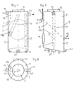
- the grease separator shown in FIGS. 1-3 for separation of fresh fat, e.g. B. from waste water from commercial kitchens or the like, consists of a separating tank 1 in the form of an upright, circular cylinder, the through an inclined partition 3 into an upper sludge trap chamber 5 and a lower separation chamber 7 divided is.
- the partition 3 is flat and can be vertical Axis of the container 1 an inclination z. B. in the area from 30 ° to 60 °, preferably an inclination of approximately 45 °.
- the sludge trap chamber 5 is through an inspection opening 9 accessible with cover in the upper container wall, access to the deposition chamber 7 enables lateral inspection opening 11 with cover in the peripheral wall of the container.
- In the sludge trap chamber 5 opens at its upper end Inlet 13 for the waste water or for the liquid mixture to be separated.
- the inlet 13 is a baffle 15 for Subsequent flow calming.
- the contained in the wastewater Sediments settle as mud on the top of the partition 3 and slide along this down to the bottom of the sludge trap chamber 5, the forms a sludge sump that tapers downwards the lowest point of a mud vent 17 with a closure member is arranged.
- a connecting tube 19 is arranged in the container 1, that connects the sludge trap chamber 5 to the separation chamber 7 and penetrates the partition 3.
- the upper confluence the connecting tube 19 is preferably located near the axis Area of the separation chamber 7 and at such a distance under the free water level in the mud trap 5, that the flowing down in the connecting tube 19 Water creates a suction that is already floating Greases in the sludge trap 1 entrained. How 1, the connecting pipe 19 runs slanted downwards towards a near the peripheral wall lying position.
- riser 25 which is at least approximately perpendicular runs within the container 1, from the lower region of the Separation chamber 7 goes out, penetrates the partition 3 and at the upper end with a branch pipe branching off to the side 27 for the pure water is connected.
- the bottom 29 of the deposition chamber 7 is slightly against the horizontal inclined, and at the lowest point of the deposition chamber 7 an emptying connection 31 with a shut-off device is arranged, to empty the entire separator.
- the separator tank 1 can on the (not shown) foundation at the lowest point of its bottom 29 and with two additional provided legs 33 to be supported. Underneath the ground can be arranged a vibration exciter 35, the separator can vibrate to detach from Suspended substances or light substances from the walls of the separator tank to favor.
- the separator shown in Figs. 1-3 offers a special simple, inexpensive and space-saving design the following operational advantages: d. H. the sediments from the upper sludge trap and the light materials from the lower separation chamber through the specified hydrostatic pressure conditions removed and z. B. withdrawn into barrels without an additional pressure increase for this removal process (e.g. using a hand pump, generating a jam in the Clean water drain etc.) is required. That at the Bottom of the separating plate 3 grease protrudes the partition 3 in thermal contact with the incoming wastewater in the sludge trap chamber 5. Since the incoming wastewater, e.g. B.
- the partition 3 can be designed as a double wall inside of which there is a heated liquid, e.g. B. heating water or electrically heated carrier oil, circulates.
- a heated liquid e.g. B. heating water or electrically heated carrier oil
- the embodiment of the fat separator shown in FIGS. 4-6 largely corresponds to that according to FIGS. 1-3 with the exception that the separator tank 41 has none round but rectangular plan.
- a level mezzanine 43, the separator tank 41 in the upper Sludge trap chamber 5 and the lower separation chamber 7 separates, is installed so that it is parallel to the narrow sides of the separator tank 41 an inclination of approx. 30 ° (Fig. 5) and also parallel to the long sides the separating tank 41 has an inclination of z. B. about 10 ° (Fig. 4), so that it is in the direction of its greatest gradient is inclined by approx. 40 ° to the horizontal.
- the rest Devices of the separator are designed analogously as in the embodiment of FIGS.
- FIGS. 7-9 corresponds in construction to that of FIGS. 1-3.
- the corresponding components have the same reference numerals provided and will not be discussed in more detail below explained.
- the embodiment according to FIGS. 7-9 is however additionally provided with an emptying and rinsing device.
- the outgoing from the lowest point of the deposition chamber 7 Drain port 31 is on the suction side Pump 51 connected, the pressure side via selective controllable valves 53, 55 optionally with an emptying riser 57 or connectable with two rinsing tubes 59, 61 is.
- One flushing pipe 59 runs on the outside of the Separation tank 1 upwards, then with a horizontal one Section 59a into the interior of the separating container 1 and ends up with an upward mouth a beam splitter 63 for generating one radially after all Sides of the flat jet emerging when the separating tank is full 1 brushed the water surface and at increasing emptying the inner walls of the sludge trap 5 rinses off.
- the other flushing pipe 61 runs from the shut-off element 53 obliquely upwards into the interior of the separation chamber 7 and ends in a beam distributor 65, which is close to the bottom of the partition 3 is arranged and one this bottom surface can produce a flat jet.
- the first step is the shut-off device 55 for the drain pipe 57 closed and the shut-off device 53 to the flushing pipes 59, 61 open.
- the pump 51 is started up so that Pumped water out of the drain port 31 and over the rinsing pipes 59, 61 into the sludge trap chamber 5 and the separation chamber 7 is pumped back, creating a vigorous Circulation and mixing of the separator content and at the same time rinsing of the inner walls via the jet distributors 63, 65 and in particular the underside of the partition 3 is effected.
- shut-off device 53 closed and the unlocking device 55 opened, so that now the entire separation content from the drain connection 31 pumped out and over the drain pipe 57 z. B. in a connected transport vehicle is pumped away.
- An additional filling connection 67 can be provided in the separator his.
- the deepest area of the Partition 3 provided an opening with a closure member 69, which is shown on a larger scale in FIG. 8A and Z. B. can be designed as a float valve. As long as the lower separation compartment 7 is filled Float flap 69 closed. If the separation chamber 7 drained via the drain connection 31 and the pump 51, so the float flap 69 opens, so that the content the sludge trap chamber 5 through the opening in the partition 3 flow into the separation chamber 7 and via the drain connection 31 can be pumped out.
- FIG. 8B shows an alternative embodiment in which the Closure member as a float ball 71 with associated ball cage 73 is formed.
- FIG. 10-12 show an embodiment of the separator, intended for the separation of starch from waste water is.
- the design largely corresponds to that of Fig. 1 - 3, and corresponding parts have the same reference numerals as shown in Figs. 1-3.
- the round separator tank 1 is inclined by approx. 45 ° Partition 3 in the upper sludge trap chamber 1 and the lower Separation chamber 7 divided.
- the separation chamber 7 serves in this case not to separate from floating Lightweight, but for separating strength, the heavier is as water. That is why it is at the top the separation chamber 7 only the vent 23, but no exhaust line.
- Which are on the inclined bottom 29 of the separation chamber 7 settling starch is withdrawn via the deduction 31 and can e.g. B. filled into barrels or a recycling be fed.
- the wastewater inlet 13 is a collecting basket or bucket 37 subordinate to catch coarse impurities.
- For better Allowing access to the grass catcher 37 is the upper inspection opening 9 eccentric to the axis of the separating tank 1 arranged. The same applies to all other parts given with reference to FIGS. 1-3.
- the separator shown in Figs. 13-15 is a gasoline separator, its basic construction in turn with the according Fig. 1 - 3 matches and so far with the same reference numerals is provided. That via the inlet 13 with a downstream Baffle 15 tapered, contaminated with gasoline Waste water enters the sludge trap chamber 5, where the sediments on the top of the inclined partition 3 settle and at the deepest point of the sludge trap 5 can be deducted on the mud vent 17.
- FIGS. 1-3 In contrast to the embodiment according to FIGS. 1-3, it runs the riser 25 of the pure water drain 27 outside the separator tank 1 and is with one in the center of the floor 29 of the separation chamber 7 arranged, vertically upwards Directed drain connector 39 connected.
- the top of the Drain connector 39 is a valve seat for a float valve 75 formed, which is guided in a cage 77 and whose float 79 on the density difference between gasoline and water is balanced, so that the float valve 75 closes the drain port 39 when the under the separating floor 3 accumulating separated gasoline layer has reached a predetermined layer thickness.
- the embodiment of the separator shown in Figs. 16-18 largely agrees with that of FIGS. 13-15 match and is so far provided with the same reference numerals.
- the separator according to FIGS. 16-18 is an oil separator trained and is also in the sludge trap chamber 5th provided with a coalescence filter 81, which the inlet of the leading from the sludge trap chamber 5 to the separation chamber 7 Connection tube 19 is connected upstream.
- the coalescence filter 81 consists of a variety of horizontal, at spaced filter mats 83, the arranged in a tubular housing open at the top are, which with the upper end of the connecting tube 19th connected is.
- a modified embodiment of the separator according to Fig. 16-18 is only shown in section in FIG. 19. It makes a difference different from the previous embodiment only by the design of the coalescence filter 81 ', which in this Case is designed as a ring filter, with a cylindrical Coalescing filter medium 83 by a support basket is worn, and upper and lower, waterproof End walls 85, 87. Water from the sludge trap 5 must flow through the coalescing filter medium 83 before it from above into the connecting pipe 19 and through this into the Separation chamber 7 can flow. Regarding all the usual ones Details are referred to the description of FIGS. 16-18.
- a level compensation channel 89 is known to the inlet 13 Design assigned to the maintenance of a possible constant water level 91 in the sludge trap chamber 5 ensures, and thus constant running-in conditions in the upper opening of the connecting pipe leading to the separation chamber 7 19.
- the clear water flows over a long time Weir edge 105 into the ring gutter, so that inlet impacts are intercepted and only to slight fluctuations in level 91 to lead.
- the one arranged at the lowest point of the inclined partition 3 Sludge discharge 17 is via a gate valve 93, a releasable coupling 95 and a flexible connecting piece 97 connected to a sludge collecting container 99, at appropriate intervals from the sludge trap chamber 5 withdrawn sludge, so that the volume of the Sludge trap 5 largely for the separation process remains available.
- a sludge collecting container 99 One from the sludge collector 99 after The leading nozzle is with a vent valve 101 Mistake.
- the sludge collecting container 99 has a bottom Drain connection 103 with shut-off device to the e.g. B. the suction hose of a disposal vehicle Pump can be connected.
- the sludge collection tank 99 has under the vent valve 101 a cavity 101A, in which when closed Valve 101 is air. After opening the valve can the sludge or residual water in the cavity rise the cavity. When changing the container nevertheless no sludge or residual water spilled.
- the overflow edge 107 is at such a height that the fat is due to the Difference in weight compared to water and therefore constantly can expire.
- the overflow edge is the one in front of it Heated fat area.
- About the Grease overflowing edge 107 enters a grease drain pipe 109, which is preferably completely or partially transparent is to be able to observe the flow of the fat.
- Via a gate valve 111 and a flexible connection 113 is the fat drain pipe 109 with a fat collecting container 115 connected to a vent 117 and a drain outlet 119 near the floor, each with shut-off device, is provided.
- Valve 117 Cavity corresponding to cavity 101A, in the open state Valve 117 grease can enter, so that from the Swap body no grease escapes when the clutch is released becomes.
- the uppermost region of the dividing plate adjacent to the fat deduction 21 3 is designed as a heatable surface 121, so that the separated fat in this area in a deductible, can be kept in a liquid state. That too is the fat loss 21 forming exhaust pipe and the overflow edge 7 are provided with suitable heating devices, such as. B. at 123 indicated. This way, a continuous Out of the fat kept liquid by heating the separation chamber 7 via the exhaust pipe 21, the overflow edge 107 and the fat drain pipe 109 in the fat collection container 115 into it, under the hydrostatic Pressure of the water volume in the separating tank 1, whose mirror height 91 through the inlet 13th assigned overflow edge 89 is set.
- the bottom 29 of the separation chamber 7 is funnel-shaped, so that the drain port 31 (with a shutoff device) (not shown) at the lowest point of the Riser 25 is located. Furthermore, the vent nozzle 117 extended as a bridge 118 to the upper separator tank.
- the shut-off device 93 is Sludge collection tank 99 (preferably with a capacity of over 100 liters) always open.
- the container 99 is filled with water when connected to the nozzle 97, the when sludge flows back into the clear water zone of the Mud trap is displaced.
- the container 99 is thus part of the sludge trap volume and a sludge thickening occurs in it by the pressure of the water column.
- the shut-off device 93 When the container 99 is filled, what on a sight glass can be seen, the shut-off device 93 is closed and that Shut-off device 101 opened. This allows the in the connecting piece 97 existing water residue in the room under the shut-off device 101 flow and runs when the clutch 95 is released not from.
- the coupling is on the container side with a lid is closed and the vent valve 101 is closed. In this state, the container can be removed and an interchangeable container can be connected.
- Figures 21 and 22 show a side view and a top view an installation variant for the separator according to the invention.
- the separator 1 which is essentially based on FIGS to 3 has been described, is preferred in this installation variant recorded underground in a concrete housing 123 and stands elevated on feet 124.
- the housing 123 has in the supervision a circular cross-section, and inside of the housing are radially extending partitions 135 and 137 are provided, which are brought together in the middle (cf. Fig. 22) and in height up to just below the bottom edge of the separator 1 extend.
- This will be sector-shaped Storage compartments 139 and 141 are formed.
- the Sludge discharge 17 is arranged above the storage compartment 139 and flows into this storage compartment, the fat, Gasoline or oil drain 21 is above the storage compartment 141 arranged and opens into this storage compartment.
- the corresponding fume cupboards are connected by a control room from remote controlled so that mud and Fat is released into the corresponding storage compartments in a controlled manner can be.
- the fill level of the storage compartments will sensed by sensors (not shown).
- the inflow is connected to a corresponding inlet line 131 and the drain 27 with a corresponding drain line 133.
- the container 123 is provided with a lid 127, one Inspection opening 147 and pumping openings 143 and 145 having.
- the fat collected in the storage compartment 139 is sucked off via the pumping opening 143 and that in the storage compartment 141 collected sludge through opening 145.
- the three openings 143, 145 and 147 are with removable covers lockable.
Applications Claiming Priority (2)
| Application Number | Priority Date | Filing Date | Title |
|---|---|---|---|
| DE19832959A DE19832959A1 (de) | 1998-07-22 | 1998-07-22 | Abscheider mit Schlammfang |
| DE19832959 | 1998-07-22 |
Publications (1)
| Publication Number | Publication Date |
|---|---|
| EP0974386A1 true EP0974386A1 (fr) | 2000-01-26 |
Family
ID=7874912
Family Applications (1)
| Application Number | Title | Priority Date | Filing Date |
|---|---|---|---|
| EP99112818A Withdrawn EP0974386A1 (fr) | 1998-07-22 | 1999-07-02 | Séparateur avec collecteur de boues |
Country Status (2)
| Country | Link |
|---|---|
| EP (1) | EP0974386A1 (fr) |
| DE (1) | DE19832959A1 (fr) |
Cited By (4)
| Publication number | Priority date | Publication date | Assignee | Title |
|---|---|---|---|---|
| EP1232779A1 (fr) * | 2001-02-15 | 2002-08-21 | Evac International Oy | Séparateur |
| EP2156871A1 (fr) * | 2008-08-22 | 2010-02-24 | Markus Baumann | Bassin d'épuration doté d'un dispositif d'évacuation |
| EP2156872A1 (fr) * | 2008-08-22 | 2010-02-24 | Markus Baumann | Bassin d'épuration doté d'un dispositif d'évacuation |
| DE102008056496A1 (de) * | 2008-11-06 | 2010-05-12 | Noah, Jörg | Fettabscheider |
Citations (11)
| Publication number | Priority date | Publication date | Assignee | Title |
|---|---|---|---|---|
| US1557340A (en) * | 1924-06-19 | 1925-10-13 | Sandmann Benno | Settling and separating apparatus |
| US1851172A (en) * | 1930-08-25 | 1932-03-29 | Gordon Arthur | Grease trap |
| DE2837554A1 (de) * | 1978-08-29 | 1980-03-06 | Ludwig Hunkel | Fluessigkeitsabscheider, insbesondere benzin- oder oelabscheider |
| US4396508A (en) * | 1981-08-27 | 1983-08-02 | Broughton Amos W | Separator for multi-phase liquids |
| DE3412500A1 (de) * | 1984-04-03 | 1985-10-10 | Passavant-Werke AG & Co KG, 6209 Aarbergen | Abscheider fuer schwimm- und sinkstoffe |
| DE4235454A1 (de) * | 1992-10-21 | 1994-04-28 | Eugen Schloetzer | Vorrichtung zum statischen Trennen von Flüssigkeitsgemischen, Emulsionen o. dgl. |
| DE4321075A1 (de) * | 1992-11-17 | 1994-05-19 | Bernhard Kessel | Fettabscheide-Anlage |
| DE9417998U1 (de) * | 1994-11-10 | 1995-01-19 | Passavant Werke | Abscheider für hochviskose Leichtstoffe, wie Fette u.dgl. aus Abwasser |
| DE4443662C1 (de) * | 1994-12-08 | 1996-06-20 | Passavant Werke | Abscheider für in Abwasser mitgeführte hochviskose Leichtstoffe |
| DE29701550U1 (de) * | 1997-01-30 | 1997-06-12 | Marcegaglia Werner | Fett- und Grobschmutzabscheider |
| DE19623869A1 (de) * | 1996-01-05 | 1997-07-10 | Hartwig Langenberg | Schmutzwassereinlauf |
-
1998
- 1998-07-22 DE DE19832959A patent/DE19832959A1/de not_active Withdrawn
-
1999
- 1999-07-02 EP EP99112818A patent/EP0974386A1/fr not_active Withdrawn
Patent Citations (11)
| Publication number | Priority date | Publication date | Assignee | Title |
|---|---|---|---|---|
| US1557340A (en) * | 1924-06-19 | 1925-10-13 | Sandmann Benno | Settling and separating apparatus |
| US1851172A (en) * | 1930-08-25 | 1932-03-29 | Gordon Arthur | Grease trap |
| DE2837554A1 (de) * | 1978-08-29 | 1980-03-06 | Ludwig Hunkel | Fluessigkeitsabscheider, insbesondere benzin- oder oelabscheider |
| US4396508A (en) * | 1981-08-27 | 1983-08-02 | Broughton Amos W | Separator for multi-phase liquids |
| DE3412500A1 (de) * | 1984-04-03 | 1985-10-10 | Passavant-Werke AG & Co KG, 6209 Aarbergen | Abscheider fuer schwimm- und sinkstoffe |
| DE4235454A1 (de) * | 1992-10-21 | 1994-04-28 | Eugen Schloetzer | Vorrichtung zum statischen Trennen von Flüssigkeitsgemischen, Emulsionen o. dgl. |
| DE4321075A1 (de) * | 1992-11-17 | 1994-05-19 | Bernhard Kessel | Fettabscheide-Anlage |
| DE9417998U1 (de) * | 1994-11-10 | 1995-01-19 | Passavant Werke | Abscheider für hochviskose Leichtstoffe, wie Fette u.dgl. aus Abwasser |
| DE4443662C1 (de) * | 1994-12-08 | 1996-06-20 | Passavant Werke | Abscheider für in Abwasser mitgeführte hochviskose Leichtstoffe |
| DE19623869A1 (de) * | 1996-01-05 | 1997-07-10 | Hartwig Langenberg | Schmutzwassereinlauf |
| DE29701550U1 (de) * | 1997-01-30 | 1997-06-12 | Marcegaglia Werner | Fett- und Grobschmutzabscheider |
Cited By (5)
| Publication number | Priority date | Publication date | Assignee | Title |
|---|---|---|---|---|
| EP1232779A1 (fr) * | 2001-02-15 | 2002-08-21 | Evac International Oy | Séparateur |
| US6645387B2 (en) * | 2001-02-15 | 2003-11-11 | Evac International Oy | Separator device |
| EP2156871A1 (fr) * | 2008-08-22 | 2010-02-24 | Markus Baumann | Bassin d'épuration doté d'un dispositif d'évacuation |
| EP2156872A1 (fr) * | 2008-08-22 | 2010-02-24 | Markus Baumann | Bassin d'épuration doté d'un dispositif d'évacuation |
| DE102008056496A1 (de) * | 2008-11-06 | 2010-05-12 | Noah, Jörg | Fettabscheider |
Also Published As
| Publication number | Publication date |
|---|---|
| DE19832959A1 (de) | 2000-01-27 |
Similar Documents
| Publication | Publication Date | Title |
|---|---|---|
| DE2805672C2 (de) | Vorrichtung zum Trennen von zwei nichtmischbaren Flüssigkeiten | |
| DE4200379A1 (de) | Geraet zum abscheiden von oel aus einem oel/wasser-gemisch | |
| DE2536644C2 (fr) | ||
| DE19623869A1 (de) | Schmutzwassereinlauf | |
| DE543898C (de) | Trennbehaelter fuer ineinander unloesliche Fluessigkeiten | |
| WO1997047829A1 (fr) | Element d'admission d'eau usee | |
| DE3908355A1 (de) | Fluessigkeitsabscheider | |
| DE2837554C2 (de) | Leichtflüssigkeitsabscheider | |
| EP0167950B1 (fr) | Appareil de séparation de liquides | |
| EP0522265B1 (fr) | Séparateur de liquide | |
| DE19632911C3 (de) | Flüssigkeitsabscheider mit Separationsvorrichtung | |
| EP0974386A1 (fr) | Séparateur avec collecteur de boues | |
| EP0588778A1 (fr) | Installation pour la purification d'eau de lavage, particulièrement dans les installations de lavage de véhicules | |
| EP0533075B1 (fr) | Séparateur de liquides | |
| AT410543B (de) | Vorrichtung zum kontinuierlichen trennen von aufschwimmbaren und sedimentierbaren stoffen aus damit verunreinigtem wasser | |
| DE3604011A1 (de) | Abscheider fuer insbesondere fette aus waessern | |
| DE102014018119B4 (de) | Vorrichtung zum Auffangen einer Flüssigkeit und zum Abscheiden von Öl aus der Flüssigkeit | |
| EP1507045A1 (fr) | Bouche d'égout dans le sol ou la chaussée avec un dispositif de retenue de liquides legères | |
| DE2418669A1 (de) | Verfahren zum reinigen von wasser und zum durchfuehren dieses verfahrens verwendete vorrichtung | |
| DE2848629A1 (de) | Fluessigkeitsabscheider | |
| DE8121718U1 (de) | Vorrichtung zum trennen zweier fluessigkeiten unterschiedlicher dichte | |
| DE10033370B4 (de) | Anlage zum Abscheiden von Sink- und fetthaltigen Schwimmstoffen aus diese Stoffe enthaltenden Abwässern | |
| EP0605777B1 (fr) | Séparateur de liquide | |
| AT399712B (de) | Vorrichtung zum entnehmen von leichtflüssigkeiten aus leichtflüssigkeitsabscheidern | |
| EP0512538B1 (fr) | Séparateur de liquides |
Legal Events
| Date | Code | Title | Description |
|---|---|---|---|
| PUAI | Public reference made under article 153(3) epc to a published international application that has entered the european phase |
Free format text: ORIGINAL CODE: 0009012 |
|
| AK | Designated contracting states |
Kind code of ref document: A1 Designated state(s): AT BE CH CY DE DK ES FI FR GB GR IE IT LI LU MC NL PT SE |
|
| AX | Request for extension of the european patent |
Free format text: AL;LT;LV;MK;RO;SI |
|
| 17P | Request for examination filed |
Effective date: 20000223 |
|
| AKX | Designation fees paid |
Free format text: AT BE CH CY DE DK ES FI FR GB GR IE IT LI LU MC NL PT SE |
|
| AXX | Extension fees paid |
Free format text: LT PAYMENT 20000223;MK PAYMENT 20000223;RO PAYMENT 20000223;SI PAYMENT 20000223 |
|
| RAP1 | Party data changed (applicant data changed or rights of an application transferred) |
Owner name: ACO SEVERIN AHLMANN GMBH & CO. KG |
|
| 17Q | First examination report despatched |
Effective date: 20021029 |
|
| STAA | Information on the status of an ep patent application or granted ep patent |
Free format text: STATUS: THE APPLICATION IS DEEMED TO BE WITHDRAWN |
|
| 18D | Application deemed to be withdrawn |
Effective date: 20040115 |