EP0974386A1 - Separator with sludge collector - Google Patents
Separator with sludge collector Download PDFInfo
- Publication number
- EP0974386A1 EP0974386A1 EP99112818A EP99112818A EP0974386A1 EP 0974386 A1 EP0974386 A1 EP 0974386A1 EP 99112818 A EP99112818 A EP 99112818A EP 99112818 A EP99112818 A EP 99112818A EP 0974386 A1 EP0974386 A1 EP 0974386A1
- Authority
- EP
- European Patent Office
- Prior art keywords
- chamber
- sludge
- sludge trap
- separator
- separation chamber
- Prior art date
- Legal status (The legal status is an assumption and is not a legal conclusion. Google has not performed a legal analysis and makes no representation as to the accuracy of the status listed.)
- Withdrawn
Links
Images


Classifications
-
- B—PERFORMING OPERATIONS; TRANSPORTING
- B01—PHYSICAL OR CHEMICAL PROCESSES OR APPARATUS IN GENERAL
- B01D—SEPARATION
- B01D21/00—Separation of suspended solid particles from liquids by sedimentation
- B01D21/30—Control equipment
- B01D21/34—Controlling the feed distribution; Controlling the liquid level ; Control of process parameters
-
- B—PERFORMING OPERATIONS; TRANSPORTING
- B01—PHYSICAL OR CHEMICAL PROCESSES OR APPARATUS IN GENERAL
- B01D—SEPARATION
- B01D17/00—Separation of liquids, not provided for elsewhere, e.g. by thermal diffusion
- B01D17/005—Separation of liquids, not provided for elsewhere, e.g. by thermal diffusion by thermal diffusion
-
- B—PERFORMING OPERATIONS; TRANSPORTING
- B01—PHYSICAL OR CHEMICAL PROCESSES OR APPARATUS IN GENERAL
- B01D—SEPARATION
- B01D17/00—Separation of liquids, not provided for elsewhere, e.g. by thermal diffusion
- B01D17/02—Separation of non-miscible liquids
- B01D17/0208—Separation of non-miscible liquids by sedimentation
-
- B—PERFORMING OPERATIONS; TRANSPORTING
- B01—PHYSICAL OR CHEMICAL PROCESSES OR APPARATUS IN GENERAL
- B01D—SEPARATION
- B01D17/00—Separation of liquids, not provided for elsewhere, e.g. by thermal diffusion
- B01D17/12—Auxiliary equipment particularly adapted for use with liquid-separating apparatus, e.g. control circuits
-
- B—PERFORMING OPERATIONS; TRANSPORTING
- B01—PHYSICAL OR CHEMICAL PROCESSES OR APPARATUS IN GENERAL
- B01D—SEPARATION
- B01D21/00—Separation of suspended solid particles from liquids by sedimentation
- B01D21/0024—Inlets or outlets provided with regulating devices, e.g. valves, flaps
-
- B—PERFORMING OPERATIONS; TRANSPORTING
- B01—PHYSICAL OR CHEMICAL PROCESSES OR APPARATUS IN GENERAL
- B01D—SEPARATION
- B01D21/00—Separation of suspended solid particles from liquids by sedimentation
- B01D21/10—Settling tanks with multiple outlets for the separated liquids
-
- B—PERFORMING OPERATIONS; TRANSPORTING
- B01—PHYSICAL OR CHEMICAL PROCESSES OR APPARATUS IN GENERAL
- B01D—SEPARATION
- B01D21/00—Separation of suspended solid particles from liquids by sedimentation
- B01D21/24—Feed or discharge mechanisms for settling tanks
- B01D21/2405—Feed mechanisms for settling tanks
-
- B—PERFORMING OPERATIONS; TRANSPORTING
- B01—PHYSICAL OR CHEMICAL PROCESSES OR APPARATUS IN GENERAL
- B01D—SEPARATION
- B01D21/00—Separation of suspended solid particles from liquids by sedimentation
- B01D21/24—Feed or discharge mechanisms for settling tanks
- B01D21/2427—The feed or discharge opening located at a distant position from the side walls
-
- B—PERFORMING OPERATIONS; TRANSPORTING
- B01—PHYSICAL OR CHEMICAL PROCESSES OR APPARATUS IN GENERAL
- B01D—SEPARATION
- B01D21/00—Separation of suspended solid particles from liquids by sedimentation
- B01D21/24—Feed or discharge mechanisms for settling tanks
- B01D21/2433—Discharge mechanisms for floating particles
-
- B—PERFORMING OPERATIONS; TRANSPORTING
- B01—PHYSICAL OR CHEMICAL PROCESSES OR APPARATUS IN GENERAL
- B01D—SEPARATION
- B01D21/00—Separation of suspended solid particles from liquids by sedimentation
- B01D21/24—Feed or discharge mechanisms for settling tanks
- B01D21/2444—Discharge mechanisms for the classified liquid
-
- B—PERFORMING OPERATIONS; TRANSPORTING
- B01—PHYSICAL OR CHEMICAL PROCESSES OR APPARATUS IN GENERAL
- B01D—SEPARATION
- B01D21/00—Separation of suspended solid particles from liquids by sedimentation
- B01D21/24—Feed or discharge mechanisms for settling tanks
- B01D21/245—Discharge mechanisms for the sediments
-
- B—PERFORMING OPERATIONS; TRANSPORTING
- B01—PHYSICAL OR CHEMICAL PROCESSES OR APPARATUS IN GENERAL
- B01D—SEPARATION
- B01D21/00—Separation of suspended solid particles from liquids by sedimentation
- B01D21/30—Control equipment
- B01D21/302—Active control mechanisms with external energy, e.g. with solenoid valve
-
- B—PERFORMING OPERATIONS; TRANSPORTING
- B01—PHYSICAL OR CHEMICAL PROCESSES OR APPARATUS IN GENERAL
- B01D—SEPARATION
- B01D21/00—Separation of suspended solid particles from liquids by sedimentation
- B01D21/30—Control equipment
- B01D21/307—Passive control mechanisms without external energy, e.g. using a float
-
- B—PERFORMING OPERATIONS; TRANSPORTING
- B01—PHYSICAL OR CHEMICAL PROCESSES OR APPARATUS IN GENERAL
- B01D—SEPARATION
- B01D21/00—Separation of suspended solid particles from liquids by sedimentation
- B01D21/009—Heating or cooling mechanisms specially adapted for settling tanks
Definitions
- the invention relates to a separator with an upstream Sludge trap, the separator being preferred a light-weight separator such as grease, petrol or oil separators acts.
- the separator can also be used as a starch separator be trained.
- a gasoline or oil separator is known with a cylindrical separator tank that passes through a horizontal partition into an upper sludge trap and a lower separation chamber is divided.
- the sludge trap and separation chamber are separated by a vertical one Manhole with overflow edge in the sludge trap and mouth connected in the deposition chamber.
- floating petrol or oil can over a Overflow edge into a drain room and from there down into a below the separation chamber in the separation tank the arranged light material collection chamber.
- a controlled one Deduction of only the separated light materials without any water components, and also a controlled one Deduction of the sludge deposited in the sludge trap chamber is not possible.
- DE-OS 42 35 454 is a device for static Separating liquid mixtures, emulsions or the like known, with a standing cylindrical container that through an inclined partition into an upper, separating space tapering downwards and into a lower, chamber tapered to the top, where in the chamber a separate, downstream separator is housed. It is a two-stage Separator for separating specifically lighter Liquids from water, with an upstream Sludge trapping is not provided.
- the invention has for its object a separator, preferably light liquid separator with upstream Form sludge traps so that they are simple, robust and compact design optimal separation both the sediments (sludge) as well as the other ingredients of the water to be cleaned and a simple deduction of the deposited substances using the specified hydrostatic Pressure ratios.
- a separator preferably light liquid separator with upstream Form sludge traps so that they are simple, robust and compact design optimal separation both the sediments (sludge) as well as the other ingredients of the water to be cleaned and a simple deduction of the deposited substances using the specified hydrostatic Pressure ratios.
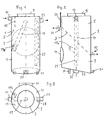
- the grease separator shown in FIGS. 1-3 for separation of fresh fat, e.g. B. from waste water from commercial kitchens or the like, consists of a separating tank 1 in the form of an upright, circular cylinder, the through an inclined partition 3 into an upper sludge trap chamber 5 and a lower separation chamber 7 divided is.
- the partition 3 is flat and can be vertical Axis of the container 1 an inclination z. B. in the area from 30 ° to 60 °, preferably an inclination of approximately 45 °.
- the sludge trap chamber 5 is through an inspection opening 9 accessible with cover in the upper container wall, access to the deposition chamber 7 enables lateral inspection opening 11 with cover in the peripheral wall of the container.
- In the sludge trap chamber 5 opens at its upper end Inlet 13 for the waste water or for the liquid mixture to be separated.
- the inlet 13 is a baffle 15 for Subsequent flow calming.
- the contained in the wastewater Sediments settle as mud on the top of the partition 3 and slide along this down to the bottom of the sludge trap chamber 5, the forms a sludge sump that tapers downwards the lowest point of a mud vent 17 with a closure member is arranged.
- a connecting tube 19 is arranged in the container 1, that connects the sludge trap chamber 5 to the separation chamber 7 and penetrates the partition 3.
- the upper confluence the connecting tube 19 is preferably located near the axis Area of the separation chamber 7 and at such a distance under the free water level in the mud trap 5, that the flowing down in the connecting tube 19 Water creates a suction that is already floating Greases in the sludge trap 1 entrained. How 1, the connecting pipe 19 runs slanted downwards towards a near the peripheral wall lying position.
- riser 25 which is at least approximately perpendicular runs within the container 1, from the lower region of the Separation chamber 7 goes out, penetrates the partition 3 and at the upper end with a branch pipe branching off to the side 27 for the pure water is connected.
- the bottom 29 of the deposition chamber 7 is slightly against the horizontal inclined, and at the lowest point of the deposition chamber 7 an emptying connection 31 with a shut-off device is arranged, to empty the entire separator.
- the separator tank 1 can on the (not shown) foundation at the lowest point of its bottom 29 and with two additional provided legs 33 to be supported. Underneath the ground can be arranged a vibration exciter 35, the separator can vibrate to detach from Suspended substances or light substances from the walls of the separator tank to favor.
- the separator shown in Figs. 1-3 offers a special simple, inexpensive and space-saving design the following operational advantages: d. H. the sediments from the upper sludge trap and the light materials from the lower separation chamber through the specified hydrostatic pressure conditions removed and z. B. withdrawn into barrels without an additional pressure increase for this removal process (e.g. using a hand pump, generating a jam in the Clean water drain etc.) is required. That at the Bottom of the separating plate 3 grease protrudes the partition 3 in thermal contact with the incoming wastewater in the sludge trap chamber 5. Since the incoming wastewater, e.g. B.
- the partition 3 can be designed as a double wall inside of which there is a heated liquid, e.g. B. heating water or electrically heated carrier oil, circulates.
- a heated liquid e.g. B. heating water or electrically heated carrier oil
- the embodiment of the fat separator shown in FIGS. 4-6 largely corresponds to that according to FIGS. 1-3 with the exception that the separator tank 41 has none round but rectangular plan.
- a level mezzanine 43, the separator tank 41 in the upper Sludge trap chamber 5 and the lower separation chamber 7 separates, is installed so that it is parallel to the narrow sides of the separator tank 41 an inclination of approx. 30 ° (Fig. 5) and also parallel to the long sides the separating tank 41 has an inclination of z. B. about 10 ° (Fig. 4), so that it is in the direction of its greatest gradient is inclined by approx. 40 ° to the horizontal.
- the rest Devices of the separator are designed analogously as in the embodiment of FIGS.
- FIGS. 7-9 corresponds in construction to that of FIGS. 1-3.
- the corresponding components have the same reference numerals provided and will not be discussed in more detail below explained.
- the embodiment according to FIGS. 7-9 is however additionally provided with an emptying and rinsing device.
- the outgoing from the lowest point of the deposition chamber 7 Drain port 31 is on the suction side Pump 51 connected, the pressure side via selective controllable valves 53, 55 optionally with an emptying riser 57 or connectable with two rinsing tubes 59, 61 is.
- One flushing pipe 59 runs on the outside of the Separation tank 1 upwards, then with a horizontal one Section 59a into the interior of the separating container 1 and ends up with an upward mouth a beam splitter 63 for generating one radially after all Sides of the flat jet emerging when the separating tank is full 1 brushed the water surface and at increasing emptying the inner walls of the sludge trap 5 rinses off.
- the other flushing pipe 61 runs from the shut-off element 53 obliquely upwards into the interior of the separation chamber 7 and ends in a beam distributor 65, which is close to the bottom of the partition 3 is arranged and one this bottom surface can produce a flat jet.
- the first step is the shut-off device 55 for the drain pipe 57 closed and the shut-off device 53 to the flushing pipes 59, 61 open.
- the pump 51 is started up so that Pumped water out of the drain port 31 and over the rinsing pipes 59, 61 into the sludge trap chamber 5 and the separation chamber 7 is pumped back, creating a vigorous Circulation and mixing of the separator content and at the same time rinsing of the inner walls via the jet distributors 63, 65 and in particular the underside of the partition 3 is effected.
- shut-off device 53 closed and the unlocking device 55 opened, so that now the entire separation content from the drain connection 31 pumped out and over the drain pipe 57 z. B. in a connected transport vehicle is pumped away.
- An additional filling connection 67 can be provided in the separator his.
- the deepest area of the Partition 3 provided an opening with a closure member 69, which is shown on a larger scale in FIG. 8A and Z. B. can be designed as a float valve. As long as the lower separation compartment 7 is filled Float flap 69 closed. If the separation chamber 7 drained via the drain connection 31 and the pump 51, so the float flap 69 opens, so that the content the sludge trap chamber 5 through the opening in the partition 3 flow into the separation chamber 7 and via the drain connection 31 can be pumped out.
- FIG. 8B shows an alternative embodiment in which the Closure member as a float ball 71 with associated ball cage 73 is formed.
- FIG. 10-12 show an embodiment of the separator, intended for the separation of starch from waste water is.
- the design largely corresponds to that of Fig. 1 - 3, and corresponding parts have the same reference numerals as shown in Figs. 1-3.
- the round separator tank 1 is inclined by approx. 45 ° Partition 3 in the upper sludge trap chamber 1 and the lower Separation chamber 7 divided.
- the separation chamber 7 serves in this case not to separate from floating Lightweight, but for separating strength, the heavier is as water. That is why it is at the top the separation chamber 7 only the vent 23, but no exhaust line.
- Which are on the inclined bottom 29 of the separation chamber 7 settling starch is withdrawn via the deduction 31 and can e.g. B. filled into barrels or a recycling be fed.
- the wastewater inlet 13 is a collecting basket or bucket 37 subordinate to catch coarse impurities.
- For better Allowing access to the grass catcher 37 is the upper inspection opening 9 eccentric to the axis of the separating tank 1 arranged. The same applies to all other parts given with reference to FIGS. 1-3.
- the separator shown in Figs. 13-15 is a gasoline separator, its basic construction in turn with the according Fig. 1 - 3 matches and so far with the same reference numerals is provided. That via the inlet 13 with a downstream Baffle 15 tapered, contaminated with gasoline Waste water enters the sludge trap chamber 5, where the sediments on the top of the inclined partition 3 settle and at the deepest point of the sludge trap 5 can be deducted on the mud vent 17.
- FIGS. 1-3 In contrast to the embodiment according to FIGS. 1-3, it runs the riser 25 of the pure water drain 27 outside the separator tank 1 and is with one in the center of the floor 29 of the separation chamber 7 arranged, vertically upwards Directed drain connector 39 connected.
- the top of the Drain connector 39 is a valve seat for a float valve 75 formed, which is guided in a cage 77 and whose float 79 on the density difference between gasoline and water is balanced, so that the float valve 75 closes the drain port 39 when the under the separating floor 3 accumulating separated gasoline layer has reached a predetermined layer thickness.
- the embodiment of the separator shown in Figs. 16-18 largely agrees with that of FIGS. 13-15 match and is so far provided with the same reference numerals.
- the separator according to FIGS. 16-18 is an oil separator trained and is also in the sludge trap chamber 5th provided with a coalescence filter 81, which the inlet of the leading from the sludge trap chamber 5 to the separation chamber 7 Connection tube 19 is connected upstream.
- the coalescence filter 81 consists of a variety of horizontal, at spaced filter mats 83, the arranged in a tubular housing open at the top are, which with the upper end of the connecting tube 19th connected is.
- a modified embodiment of the separator according to Fig. 16-18 is only shown in section in FIG. 19. It makes a difference different from the previous embodiment only by the design of the coalescence filter 81 ', which in this Case is designed as a ring filter, with a cylindrical Coalescing filter medium 83 by a support basket is worn, and upper and lower, waterproof End walls 85, 87. Water from the sludge trap 5 must flow through the coalescing filter medium 83 before it from above into the connecting pipe 19 and through this into the Separation chamber 7 can flow. Regarding all the usual ones Details are referred to the description of FIGS. 16-18.
- a level compensation channel 89 is known to the inlet 13 Design assigned to the maintenance of a possible constant water level 91 in the sludge trap chamber 5 ensures, and thus constant running-in conditions in the upper opening of the connecting pipe leading to the separation chamber 7 19.
- the clear water flows over a long time Weir edge 105 into the ring gutter, so that inlet impacts are intercepted and only to slight fluctuations in level 91 to lead.
- the one arranged at the lowest point of the inclined partition 3 Sludge discharge 17 is via a gate valve 93, a releasable coupling 95 and a flexible connecting piece 97 connected to a sludge collecting container 99, at appropriate intervals from the sludge trap chamber 5 withdrawn sludge, so that the volume of the Sludge trap 5 largely for the separation process remains available.
- a sludge collecting container 99 One from the sludge collector 99 after The leading nozzle is with a vent valve 101 Mistake.
- the sludge collecting container 99 has a bottom Drain connection 103 with shut-off device to the e.g. B. the suction hose of a disposal vehicle Pump can be connected.
- the sludge collection tank 99 has under the vent valve 101 a cavity 101A, in which when closed Valve 101 is air. After opening the valve can the sludge or residual water in the cavity rise the cavity. When changing the container nevertheless no sludge or residual water spilled.
- the overflow edge 107 is at such a height that the fat is due to the Difference in weight compared to water and therefore constantly can expire.
- the overflow edge is the one in front of it Heated fat area.
- About the Grease overflowing edge 107 enters a grease drain pipe 109, which is preferably completely or partially transparent is to be able to observe the flow of the fat.
- Via a gate valve 111 and a flexible connection 113 is the fat drain pipe 109 with a fat collecting container 115 connected to a vent 117 and a drain outlet 119 near the floor, each with shut-off device, is provided.
- Valve 117 Cavity corresponding to cavity 101A, in the open state Valve 117 grease can enter, so that from the Swap body no grease escapes when the clutch is released becomes.
- the uppermost region of the dividing plate adjacent to the fat deduction 21 3 is designed as a heatable surface 121, so that the separated fat in this area in a deductible, can be kept in a liquid state. That too is the fat loss 21 forming exhaust pipe and the overflow edge 7 are provided with suitable heating devices, such as. B. at 123 indicated. This way, a continuous Out of the fat kept liquid by heating the separation chamber 7 via the exhaust pipe 21, the overflow edge 107 and the fat drain pipe 109 in the fat collection container 115 into it, under the hydrostatic Pressure of the water volume in the separating tank 1, whose mirror height 91 through the inlet 13th assigned overflow edge 89 is set.
- the bottom 29 of the separation chamber 7 is funnel-shaped, so that the drain port 31 (with a shutoff device) (not shown) at the lowest point of the Riser 25 is located. Furthermore, the vent nozzle 117 extended as a bridge 118 to the upper separator tank.
- the shut-off device 93 is Sludge collection tank 99 (preferably with a capacity of over 100 liters) always open.
- the container 99 is filled with water when connected to the nozzle 97, the when sludge flows back into the clear water zone of the Mud trap is displaced.
- the container 99 is thus part of the sludge trap volume and a sludge thickening occurs in it by the pressure of the water column.
- the shut-off device 93 When the container 99 is filled, what on a sight glass can be seen, the shut-off device 93 is closed and that Shut-off device 101 opened. This allows the in the connecting piece 97 existing water residue in the room under the shut-off device 101 flow and runs when the clutch 95 is released not from.
- the coupling is on the container side with a lid is closed and the vent valve 101 is closed. In this state, the container can be removed and an interchangeable container can be connected.
- Figures 21 and 22 show a side view and a top view an installation variant for the separator according to the invention.
- the separator 1 which is essentially based on FIGS to 3 has been described, is preferred in this installation variant recorded underground in a concrete housing 123 and stands elevated on feet 124.
- the housing 123 has in the supervision a circular cross-section, and inside of the housing are radially extending partitions 135 and 137 are provided, which are brought together in the middle (cf. Fig. 22) and in height up to just below the bottom edge of the separator 1 extend.
- This will be sector-shaped Storage compartments 139 and 141 are formed.
- the Sludge discharge 17 is arranged above the storage compartment 139 and flows into this storage compartment, the fat, Gasoline or oil drain 21 is above the storage compartment 141 arranged and opens into this storage compartment.
- the corresponding fume cupboards are connected by a control room from remote controlled so that mud and Fat is released into the corresponding storage compartments in a controlled manner can be.
- the fill level of the storage compartments will sensed by sensors (not shown).
- the inflow is connected to a corresponding inlet line 131 and the drain 27 with a corresponding drain line 133.
- the container 123 is provided with a lid 127, one Inspection opening 147 and pumping openings 143 and 145 having.
- the fat collected in the storage compartment 139 is sucked off via the pumping opening 143 and that in the storage compartment 141 collected sludge through opening 145.
- the three openings 143, 145 and 147 are with removable covers lockable.
Abstract
Description
Die Erfindung betrifft einen Abscheider mit vorgeschaltetem Schlammfang, wobei es sich bei dem Abscheider vorzugsweise um einen Leichtstoffabscheider wie Fett-, Benzin- oder Ölabscheider handelt. Der Abscheider kann aber auch als Stärkeabscheider ausgebildet sein.The invention relates to a separator with an upstream Sludge trap, the separator being preferred a light-weight separator such as grease, petrol or oil separators acts. The separator can also be used as a starch separator be trained.
Aus DE-OS 28 37 554 ist ein Benzin- oder Ölabscheider bekannt mit einem zylindrischen Abscheidebehälter, der durch einen horizontalen Trennboden in eine obere Schlammfangkammer und eine untere Abscheidekammer unterteilt ist. Schlammfangkammer und Abscheidekammer sind durch einen lotrechten Schacht mit Überlaufkante in der Schlammfangkammer und Ausmündung in der Abscheidekammer verbunden. In der Abscheidekammer aufschwimmendes Benzin oder Öl kann über eine Überlaufkante in einen Ablaufraum und von dort nach unten in eine unterhalb der Abscheidekammer im Abscheidebehälter angeordnete Leichtstoffsammelkammer ablaufen. Ein kontrollierter Abzug lediglich der abgeschiedenen Leichtstoffe ohne mitgeführte Wasseranteile, und ebenso ein kontrollierter Abzug des in der Schlammfangkammer abgesetzten Schlammes ist dabei jedoch nicht möglich.From DE-OS 28 37 554 a gasoline or oil separator is known with a cylindrical separator tank that passes through a horizontal partition into an upper sludge trap and a lower separation chamber is divided. The sludge trap and separation chamber are separated by a vertical one Manhole with overflow edge in the sludge trap and mouth connected in the deposition chamber. In the separation chamber floating petrol or oil can over a Overflow edge into a drain room and from there down into a below the separation chamber in the separation tank the arranged light material collection chamber. A controlled one Deduction of only the separated light materials without any water components, and also a controlled one Deduction of the sludge deposited in the sludge trap chamber is not possible.
Aus DE-OS 42 35 454 ist eine Vorrichtung zum statischen Trennen von Flüssigkeitsgemischen, Emulsionen oder dergleichen bekannt, mit einem stehend zylindrischen Behälter, der durch einen schräg geneigten Trennboden in einen oberen, nach unten spitz zulaufenden Abscheideraum und in eine untere, nach oben spitz zulaufende Kammer unterteilt ist, wobei in der Kammer ein gesonderter, nachgeschalteter Abscheider untergebracht ist. Es handelt sich um einen zweistufigen Abscheider für das Abtrennen spezifisch leichterer Flüssigkeiten aus Wasser, wobei ein vorgeschalteter Schlammfang nicht vorgesehen ist.DE-OS 42 35 454 is a device for static Separating liquid mixtures, emulsions or the like known, with a standing cylindrical container that through an inclined partition into an upper, separating space tapering downwards and into a lower, chamber tapered to the top, where in the chamber a separate, downstream separator is housed. It is a two-stage Separator for separating specifically lighter Liquids from water, with an upstream Sludge trapping is not provided.
Der Erfindung liegt die Aufgabe zugrunde, einen Abscheider, vorzugsweise Leichtflüssigkeitsabscheider mit vorgeschaltetem Schlammfang so auszubilden, daß er bei einfacher, robuster und kompakter Bauweise eine optimale Trennung sowohl der Sinkstoffe (Schlamm) als auch der übrigen Inhaltstoffe des zu reinigenden Wassers und einen einfachen Abzug der abgeschiedenen Stoffe unter Ausnützung der vorgegebenen hydrostatischen Druckverhältnisse ermöglicht.The invention has for its object a separator, preferably light liquid separator with upstream Form sludge traps so that they are simple, robust and compact design optimal separation both the sediments (sludge) as well as the other ingredients of the water to be cleaned and a simple deduction of the deposited substances using the specified hydrostatic Pressure ratios.
Die erfindungsgemäße Lösung der Aufgabe für einen Leichtflüssigkeitsabscheider
ist im Anspruch 1 angegeben. Eine
weitere vorteilhafte Lösung bei Anwendung auf einen Stärkeabscheider
ist in Anspruch 13 angegeben.The inventive solution to the problem for a light liquid separator
is specified in
In den Zeichnungen sind verschiedene Ausführungsformen des erfindungsgemäßen Abscheiders in stark vereinfachten schematischen Ansichten dargestellt, und zwar, soweit nicht anders angegeben, jeweils in einer Ansicht von vorn, von der Seite und von oben. Es zeigen:
- Fig. 1 - 3
- einen Fettabscheider in runder Bauweise;
- Fig. 4 - 6
- einen Fettabscheider in Rechteckbauweise;
- Fig. 7 - 9
- einen Fettabscheider ähnlich Fig. 1 - 3, jedoch mit zusätzlicher Entleer- und Spüleinrichtung;
- Fig. 8A und 8B
- ein Detail von Fig. 8 in zwei Alternativen;
- Fig. 10 - 12
- einen Stärkeabscheider;
- Fig. 13 - 15
- einen Benzinabscheider mit Schwimmerverschluß (Fig. 14 teilweise im Schnitt);
- Fig. 16 - 18
- einen Ölabscheider mit zusätzlicher Koaleszenz-Abscheidestute (Fig. 16 teilweise und Fig. 17 ganz geschnitten);
- Fig. 19
- ähnlich Fig. 17 einen Ölabscheider mit anderer Bauart des Koaleszenzfilters;
- Fig. 20
- einen erfindungsgemäßen Fettabscheider mit zusätzlichen Sammelbehältern, nur in Seitenansicht;
- Fig. 21 und 22
- einen Abscheider in unterirdischer Installation
- 1 - 3
- a round grease separator;
- 4 - 6
- a rectangular grease separator;
- Fig. 7-9
- a grease separator similar to Figures 1-3, but with additional emptying and rinsing;
- Figures 8A and 8B
- a detail of Figure 8 in two alternatives;
- Figures 10-12
- a starch separator;
- Figures 13-15
- a gasoline separator with float lock (Fig. 14 partially in section);
- Figures 16-18
- an oil separator with additional coalescence separating mare (Fig. 16 partially and Fig. 17 completely cut);
- Fig. 19
- similar to FIG. 17, an oil separator with a different type of coalescence filter;
- Fig. 20
- a grease separator according to the invention with additional collecting containers, only in side view;
- 21 and 22
- a separator in an underground installation
Der in Fig. 1 - 3 dargestellte Fettabscheider zum Abscheiden
von Frischfett, z. B. aus Abwässern von Großküchenanlagen
oder dergleichen, besteht aus einem Abscheidebehälter 1
in Form eines aufrechtstehenden, kreisrunden Zylinders, der
durch einen schrägen Trennboden 3 in eine obere Schlammfangkammer
5 und eine untere Abscheidekammer 7 unterteilt
ist. Der Trennboden 3 ist eben und kann gegenüber der vertikalen
Achse des Behälters 1 eine Neigung z. B. im Bereich
von 30° - 60°, vorzugsweise eine Neigung von ca. 45°, aufweisen.
Die Schlammfangkammer 5 ist durch eine Revisionsöffnung
9 mit Deckel in der oberen Behälterwandung zugänglich,
den Zugang zur Abscheidekammer 7 ermöglicht eine
seitliche Revisionsöffnung 11 mit Deckel in der Behälterumfangswandung.The grease separator shown in FIGS. 1-3 for separation
of fresh fat, e.g. B. from waste water from commercial kitchens
or the like, consists of a separating
In die Schlammfangkammer 5 mündet an ihrem oberen Ende ein
Zulauf 13 für das Abwasser bzw. für das zu trennende Flüssigkeitsgemisch.
Dem Zulauf 13 ist eine Prallwand 15 zur
Strömungsberuhigung nachgeordnet. Die im Abwasser enthaltenen
Sinkstoffe setzen sich als Schlamm auf der Oberseite
des Trennbodens 3 ab und rutschen auf diesem entlang nach
unten bis zum unteren Bereich der Schlammfangkammer 5, der
einen nach unten spitz zulaufenden Schlammsumpf bildet, an
dessen tiefsten Stelle ein Schlammabzug 17 mit Verschlußorgan
angeordnet ist.In the
In dem Behälter 1 ist ein Verbindungsrohr 19 angeordnet,
das die Schlammfangkammer 5 mit der Abscheidekammer 7 verbindet
und den Trennboden 3 durchdringt. Die obere Einmündung
des Verbindungsrohres 19 liegt vorzugsweise im achsnahen
Bereich der Abscheidekammer 7 und in solchem Abstand
unter dem sich im Schlammfang 5 einstellenden freien Wasserspiegel,
daß das im Verbindungsrohr 19 nach unten strömende
Wasser einen Sog erzeugt, der etwa bereits aufschwimmende
Fettanteile in der Schlammfangkammer 1 mitreißt. Wie
aus Fig. 1 ersichtlich, verläuft das Verbindungsrohr 19
schräg nach unten geneigt in Richtung auf eine nahe der Umfangswandung
liegende Stelle. Dort ist am unteren Ende des
Verbindungsrohres 19 ein Rohrstutzen 19a angefügt, der ungefähr
in Tangentialrichtung und mit einer nach oben gerichteten
Neigung verläuft, so daß das aus der Schlammfangkammer
5 durch das Verbindungsrohr 19 in die Abscheidekammer
7 fließende Flüssigkeitsgemisch mit einer tangential
und nach oben gerichteten Bewegungskomponente in die Abscheidekammer
7 eintritt. In der Abscheidekammer trennen
sich die spezifisch leichteren Stoffe, insbesondere Fett,
von dem Wasser und sammeln sich im oberen Bereich der Abscheidekammer
7 unterhalb der Trennwand 3 an, der einen
nach oben spitz zulaufenden Leichtstoffsammelraum bildet.
An dessen höchsten Stelle ist ein Fettabzug 21 mit Absperrorgan
vorgesehen, durch den das abgeschiedene Fett abgezogen
und z. B. in einem Sammelbehälter aufgefangen werden
kann. Der Fettabzug 21 ist ferner mit einer schematisch
dargestellten Entlüftung 23 versehen, die dafür sorgt, daß
die Abscheidekammer 7 immer ohne Freispiegel vollständig
bis zu ihrem höchsten Punkt gefüllt ist.A connecting
Für den Abzug des Reinwassers aus der Abscheidekammer 7
dient ein Steigrohr 25, das mindestens annähernd lotrecht
innerhalb des Behälters 1 verläuft, vom unteren Bereich der
Abscheidekammer 7 ausgeht, die Trennwand 3 durchdringt und
am oberen Ende mit einer seitlich abzweigenden Abzugsleitung
27 für das Reinwasser verbunden ist.For the removal of the pure water from the
Der Boden 29 der Abscheidekammer 7 ist leicht gegen die Horizontale
geneigt, und am tiefsten Punkt der Abscheidekammer
7 ist ein Entleeranschluß 31 mit Absperrorgan angeordnet,
um den gesamten Abscheider zu entleeren. Der Abscheidebehälter
1 kann auf dem (nicht dargestellten) Fundament
am tiefsten Punkt seines Bodens 29 und mit zwei zusätzlich
vorgesehenen Beinen 33 aufgestützt sein. Unter dem Boden
kann ein Schwingungserreger 35 angeordnet sein, der den Abscheider
in Vibration versetzen kann, um die Ablösung von
Sinkstoffen oder Leichtstoffen von den Wänden des Abscheidebehälters
zu begünstigen.The bottom 29 of the
Der in Fig. 1 - 3 dargestellte Abscheider bietet bei besonders
einfacher, preisgünstiger und platzsparender Bauweise
die folgenden betrieblichen Vorteile: Das Abscheidegut,
d. h. die Sinkstoffe aus der oberen Schlammfangkammer und
die Leichtstoffe aus der unteren Abscheidekammer, können
durch die vorgegebenen hydrostatischen Druckverhältnisse
entnommen und z. B. in Fässer abgezogen werden, ohne daß
für diesen Entnahmevorgang eine zusätzliche Druckerhöhung
(z. B. Verwendung einer Handpumpe, Erzeugen eines Staus im
Reinwasserablauf usw.) erforderlich ist. Das sich an der
Unterseite des Trennbodens 3 ansammelnde Fett steht über
den Trennboden 3 in Wärmekontakt mit dem zulaufenden Abwasser
in der Schlammfangkammer 5. Da das zulaufende Abwasser,
z. B. aus Großküchen und ähnlichen Betrieben, in der Regel
mit erhöhter Temperatur zufließt, trägt es dazu bei, das
Fett an der Unterseite des Trennbodens 3 zu erwärmen und in
flüssigem, abzugsfähigen Zustand zu erhalten. Eine zusätzliche
Beheizung der Leichtstoffe ist daher entbehrlich,
kann aber, falls erforderlich, ebenfalls vorgesehen werden.
Beispielsweise kann der Trennboden 3 als Doppelwand ausgebildet
werden, in deren Innenraum eine erwärmte Flüssigkeit,
z. B. Heizungswasser oder elektrisch beheiztes Trägeröl,
zirkuliert.The separator shown in Figs. 1-3 offers a special
simple, inexpensive and space-saving design
the following operational advantages:
d. H. the sediments from the upper sludge trap and
the light materials from the lower separation chamber
through the specified hydrostatic pressure conditions
removed and z. B. withdrawn into barrels without
an additional pressure increase for this removal process
(e.g. using a hand pump, generating a jam in the
Clean water drain etc.) is required. That at the
Bottom of the separating
Die in Fig. 4 - 6 dargestelle Ausführungsform des Fettabscheiders
stimmt mit der gemäß Fig. 1 - 3 weitgehend überein
mit der Ausnahme, daß der Abscheidebhälter 41 keinen
runden, sondern rechteckigen Grundriß hat. Ein ebener Zwischenboden
43, der den Abscheidebehälter 41 in die obere
Schlammfangkammer 5 und die untere Abscheidekammer 7
trennt, ist so eingebaut, daß er in Richtung parallel zu
den Schmalseiten des Abscheidebehälters 41 eine Neigung von
ca. 30° (Fig. 5) und zusätzlich parallel zu den Längsseiten
des Abscheidebehälters 41 eine Neigung von z. B. ca. 10°
(Fig. 4) aufweist, so daß er in Richtung seines größten Gefälles
um ca. 40° zur Horizontalen geneigt ist. Alle übrigen
Einrichtungen des Abscheiders sind analog ausgebildet
wie bei der Ausführungsform nach Fig. 1 - 3 und sind deshalb
auch mit den gleichen Bezugszeichen bezeichnet. Der
Zulauf 13 mit nachgeordneter Prallwand 15, der Reinwasserablauf
27 und der Schlammabzug 17 sind alle an der gleichen
Schmalseite 45 des Abscheidebehälters 41 angeordnet (vgl.
Fig. 4 und Fig. 6), während auf der gegenüberliegenden
Schmalseite 47 nur der Fettabzug 21 mit Entlüftung 23 an
der höchsten Stelle unterhalb des Zwischenbodens 43 angeordnet
ist. Nahe dieser Schmalseitenwand 47 erstreckt sich
das Verbindungsrohr 19, das die Schlammfangkammer 5 mit der
Abscheidekammer 7 verbindet, senkrecht nach unten. Mit der
Ausführungsform nach Fig. 4 - 6 werden bei ähnlich einfacher,
preisgünstiger, robuster und platzsparender Bauweise
die gleichen betrieblichen Vorteile erzielt wie bei der
Ausführungsform nach Fig. 1 - 3.The embodiment of the fat separator shown in FIGS. 4-6
largely corresponds to that according to FIGS. 1-3
with the exception that the
Die in Fig. 7 - 9 darstellte Ausführungsform des Fettabscheiders
entspricht in ihrer Bauweise der nach Fig. 1 - 3.
Die übereinstimmenden Bauteile sind mit den gleichen Bezugszeichen
versehen und werden im folgenden nicht näher
erläutert. Die Ausführungsform nach Fig. 7 - 9 ist jedoch
zusätzlich mit einer Entleer- und Spüleinrichtung versehen.
Der von der tiefsten Stelle der Abscheidekammer 7 ausgehende
Entleerungsanschluß 31 ist an die Saugseite einer
Pumpe 51 angeschlossen, deren Druckseite über selektiv
steuerbare Ventile 53, 55 wahlweise mit einem Entleerungssteigrohr
57 oder mit zwei Spülrohren 59, 61 verbindbar
ist. Das eine Spülrohr 59 verläuft an der Außenseite des
Abscheidebehälters 1 nach oben, dann mit einem horizontalen
Abschnitt 59a in das Innere des Abscheidebehälters 1 hinein
und hat am Ende eine nach oben gerichtete Ausmündung mit
einem Strahlverteiler 63 zum Erzeugen eines radial nach allen
Seiten austretenden Flachstrahls, der bei vollem Abscheidebehälter
1 die Wasseroberfläche bestreicht und bei
zunehmender Entleerung die Innenwände der Schlammfangkammer
5 abspült. Das andere Spülrohr 61 verläuft vom Absperrorgan
53 schräg nach oben in das Innere der Abscheidekammer 7
hinein und endet in einem Strahlverteiler 65, der dicht an
der Unterseite des Trennbodens 3 angeordnet ist und einen
diese Unterseite abspülenden Flachstrahl erzeugen kann.The embodiment of the fat separator shown in FIGS. 7-9
corresponds in construction to that of FIGS. 1-3.
The corresponding components have the same reference numerals
provided and will not be discussed in more detail below
explained. The embodiment according to FIGS. 7-9 is however
additionally provided with an emptying and rinsing device.
The outgoing from the lowest point of the
Soll der Abscheidebehälter 1 entleert werden, so wird zunächst
das Absperrorgan 55 für das Entleerungssteigrohr 57
geschlossen und das Absperrorgan 53 zu den Spülrohren 59,
61 geöffnet. Die Pumpe 51 wird in Betrieb genommen, so daß
Wasser aus dem Entleerungsanschluß 31 abgepumpt und über
die Spülrohre 59, 61 in die Schlammfangkammer 5 und die Abscheidekammer
7 zurückgepumpt wird, wodurch eine kräftige
Umwälzung und Vermischung des Abscheiderinhalts und gleichzeitig
über die Strahlverteiler 63, 65 ein Abspülen der Innenwände
und insbesondere der Unterseite des Trennbodens 3
bewirkt wird. Nach ausreichendem Spülvorgang wird das Absperrorgan
53 geschlossen und das Aufsperrorgan 55 geöffnet,
so daß nun der gesamte Abscheideinhalt aus dem Entleerungsanschluß
31 abgepumpt und über das Entleerungssteigrohr
57 z. B. in ein angeschlossenes Transportfahrzeug
weggempumpt wird. Für ein anschließendes Wiederbefüllen des
Abscheiders kann ein zusätzlicher Füllanschluß 67 vorgesehen
sein.If the
Beim Entleeren des Abscheiders ist es wichtig, daß auch
der Inhalt der oberen Schlammfangkammer 5 nicht über den
Schlammabzug 17, sondern über den Entleerungsanschluß 31
abgezogen wird. Zu diesem Zweck ist im tiefsten Bereich des
Trennbodens 3 eine Öffnung mit einem Verschlußorgan 69 vorgesehen,
das in Fig. 8A in größerem Maßstab dargestellt ist
und z. B. als Schwimmerklappe ausgebildet sein kann. Solange
das untere Abscheideabteil 7 gefüllt ist, ist die
Schwimmerklappe 69 geschlossen. Wird die Abscheidekammer 7
über den Entleerungsanschluß 31 und die Pumpe 51 entleert,
so öffnet die Schwimmerklappe 69, so daß auch der Inhalt
der Schlammfangkammer 5 durch die Öffnung im Trennboden 3
in die Abscheidekammer 7 abfließen und über den Entleerungsanschluß
31 abgepumpt werden kann.When emptying the separator it is important that too
the content of the upper
Fig. 8B zeigt eine alternative Ausführungsform, bei der das
Verschlußorgan als Schwimmerkugel 71 mit zugehörigem Kugelkäfig
73 ausgebildet ist.8B shows an alternative embodiment in which the
Closure member as a
Fig. 10 - 12 zeigen eine Ausführungsform des Abscheiders,
der für das Abscheiden von Stärke aus Abwasser bestimmt
ist. Die Bauform stimmt weitgehend überein mit der von Fig.
1 - 3, und entsprechende Teile sind mit den gleichen Bezugszeichen
wie in Fig. 1 - 3 bezeichnet. Der runde Abscheidebehälter
1 wird durch den um ca. 45° geneigten
Trennboden 3 in die obere Schlammfangkammer 1 und die untere
Abscheidekammer 7 geteilt. Die Abscheidekammer 7 dient
in diesem Fall nicht zum Abscheiden von aufschwimmendem
Leichtstoff, sondern zum Abscheiden von Stärke, die schwerer
ist als Wasser. Deshalb befindet sich am obersten Punkt
der Abscheidekammer 7 nur die Entlüftung 23, aber keine Abzugsleitung.
Die sich am geneigten Boden 29 der Abscheidekammer
7 absetzende Stärke wird über den Abzug 31 entnommen
und kann z. B. in Fässer abgefüllt bzw. einer Verwertung
zugeführt werden. In der Schlammfangkammer 5 setzt sich auf
der Oberseite des Trennbodens 3 Schlamm vermischt mit
Stärke ab, der über den Schlammabzug 17 entnommen werden
kann. Dem Abwasserzulauf 13 ist ein Fangkorb oder -eimer 37
zum Auffangen grober Verunreinigungen nachgeordnet. Um besseren
Zugang zu dem Fangkorb 37 zu ermöglichen, ist die
obere Revisionsöffnung 9 exzentrisch zur Achse des Abscheidebehälters
1 angeordnet. Für alle übrigen Teile gilt die
anhand von Fig. 1 - 3 gegebene Beschreibung.10-12 show an embodiment of the separator,
intended for the separation of starch from waste water
is. The design largely corresponds to that of Fig.
1 - 3, and corresponding parts have the same reference numerals
as shown in Figs. 1-3. The
Der in Fig. 13 - 15 dargestellte Abscheider ist ein Benzinabscheider,
dessen Grundkonstruktion wiederum mit der gemäß
Fig. 1 - 3 übereinstimmt und insoweit mit gleichen Bezugszeichen
versehen ist. Das über den Zulauf 13 mit nachgeschalteter
Prallwand 15 zulaufende, mit Benzin verunreinigte
Abwasser gelangt in die Schlammfangkammer 5, wo sich
die Sinkstoffe an der Oberseite des geneigten Trennbodens 3
absetzen und an der tiefsten Stelle der Schlammfangkammer 5
am Schlammabzug 17 abgezogen werden können. Nahe dem Wasserspiegel
in der Schlammfangkammer 5, dessen Höhe durch
die Höhe des Reinwasserabzugs 27 festgelegt ist, strömt das
Wasser in die Einlauföffnung des Verbindungsrohrs 19, wobei
Leichtstoffe mitgerissen werden, und gelangt in die untere
Abscheidekammer 7, wo das Benzin bzw. die sonstigen Leichtstoffe
aufschwimmen, sich an der Unterseite des Trennbodens
3 ansammeln und an der höchsten Stelle der Abscheidekammer
7 über den mit Entlüftung 23 versehenen Benzinabzug 21 abgezogen
werden können.The separator shown in Figs. 13-15 is a gasoline separator,
its basic construction in turn with the according
Fig. 1 - 3 matches and so far with the same reference numerals
is provided. That via the
Im Unterschied zur Ausführungsform nach Fig. 1 - 3 verläuft
das Steigrohr 25 des Reinwasserabzugs 27 außerhalb des Abscheidebehälters
1 und ist mit einem im Zentrum des Bodens
29 der Abscheidekammer 7 angeordneten, senkrecht nach oben
gerichteten Ablaufstutzen 39 verbunden. Das obere Ende des
Ablaufstutzens 39 ist als Ventilsitz für ein Schwimmerventil
75 ausgebildet, das in einem Käfig 77 geführt ist und
dessen Schwimmer 79 auf den Dichteunterschied zwischen Benzin
und Wasser austariert ist, so daß das Schwimmerventil
75 den Ablaufstutzen 39 verschließt, wenn die sich unter
dem Trennboden 3 ansammelnde abgeschiedene Benzinschicht
eine vorgegebene Schichtdicke erreicht hat.In contrast to the embodiment according to FIGS. 1-3, it runs
the
Die in Fig. 16 - 18 dargestellte Ausführungsform des Abscheiders
stimmt mit der gemäß Fig. 13 - 15 weitgehend
überein und ist insoweit mit gleichen Bezugszeichen versehen.
Der Abscheider nach Fig. 16 - 18 ist als Ölabscheider
ausgebildet und ist zusätzlich in der Schlammfangkammer 5
mit einem Koaleszenzfilter 81 versehen, welches dem Einlauf
des von der Schlammfangkammer 5 zur Abscheidekammer 7 führenden
Verbindungsrohres 19 vorgeschaltet ist. Das Koaleszenzfiler
81 besteht aus einer Vielzahl von horizontalen,
in Abständen voneinander angeordneten Filtermatten 83, die
in einem oben offenen, rohrförmigen Gehäuse angeordnet
sind, welches mit dem oberen Ende des Verbindungsrohres 19
verbunden ist. Das vom freien Wasserspiegel in der Schlammfangkammer
5 in das Koaleszenzfilter 81 einströmende Wasser
muß die Koaleszenzfiltermatten 83 durchströmen, bevor es
durch das Verbindungsrohr 19 in die Abscheidekammer 7 gelangt,
wo sich verbliebenes Öl oder sonstige Leichtstoffe
an der Unterseite des Trennbodens 3 ansammeln und an der
höchsten Stelle durch den Ölabzug 21 abgezogen werden
können. The embodiment of the separator shown in Figs. 16-18
largely agrees with that of FIGS. 13-15
match and is so far provided with the same reference numerals.
The separator according to FIGS. 16-18 is an oil separator
trained and is also in the sludge trap chamber 5th
provided with a
Eine abgewandelte Ausführungsform des Abscheiders nach Fig.
16 - 18 ist in Fig. 19 nur im Schnitt dargestellt. Sie unterscheidet
sich von der vorhergehenden Ausführungsform nur
durch die Bauform des Koaleszenzfilters 81', das in diesem
Fall als Ringfilter ausgebildet ist, mit einem zylindrischen
Koaleszenzfiltermedium 83, das von einem Stützkorb
getragen wird, und oberen und unteren, wasserundurchlässigen
Abschlußwänden 85, 87. Wasser aus der Schlammfangkammer
5 muß durch das Koaleszenzfiltermedium 83 strömen, bevor es
von oben in das Verbindungsrohr 19 und durch dieses in die
Abscheidekammer 7 strömen kann. Bezüglich aller üblichen
Einzelheiten wird auf die Beschreibung zu Fig. 16 - 18 verwiesen.A modified embodiment of the separator according to Fig.
16-18 is only shown in section in FIG. 19. It makes a difference
different from the previous embodiment only
by the design of the coalescence filter 81 ', which in this
Case is designed as a ring filter, with a cylindrical
Coalescing filter medium 83 by a support basket
is worn, and upper and lower,
Die in Fig. 20 schematisch in Seitenansicht dargestellte
Ausführungsform des erfindungsgemäßen Abscheiders stimmt,
soweit es den eigentlichen Abscheidebehälter 1 betrifft,
weitgehend mit der in Fig. 1 - 3 gezeigten Ausführungsform
überein. Es werden deshalb gleiche Bezugszeichen wie in
Fig. 1 - 3 verwendet, und für die Detailbeschreibung wird
auf die Beschreibung zu Fig. 1 - 3 verwiesen. Nachstehend
werden nur die von Fig. 1 - 3 abweichenden Details beschrieben.The schematically shown in Fig. 20 in side view
Embodiment of the separator according to the invention is correct,
as far as the
Dem Zulauf 13 ist eine Niveauausgleichsrinne 89 bekannter
Bauart zugeordnet, die für die Aufrechterhaltung eines möglichst
konstanten Wasserspiegels 91 in der Schlammfangkammer
5 sorgt, und damit für konstante Einlaufbedingungen in
die obere Öffnung des zur Abscheidekammer 7 führenden Verbindungsrohres
19. Das Klarwasser fließt über eine lange
Wehrkante 105 in die Ringrinne, so daß Zulaufstöße abgefangen
werden und nur zu geringen Schwankungen des Niveaus 91
führen. A
Der an der tiefsten Stelle des geneigten Trennbodens 3 angeordnete
Schlammabzug 17 ist über einen Absperrschieber
93, eine lösbare Kupplung 95 und einen flexiblen Anschlußstutzen
97 mit einem Schlammsammelbehälter 99 verbunden,
der in geeigneten Zeitabständen aus der Schlammfangkammer 5
abgezogenen Schlamm aufnehmen kann, so daß das Volumen der
Schlammfangkammer 5 weitgehend für den Abscheidevorgang
verfügbar bleibt. Ein vom Schlammsammelbehälter 99 nach
oben führender Stutzen ist mit einem Entlüftungsventil 101
versehen. Ferner hat der Schlammsammelbehälter 99 einen bodennahen
Entleerungsanschluß 103 mit Absperrorgan, an den
z. B. der Absaugschlauch eines Entsorgungsfahrzeugs mit
Pumpe angeschlossen werden kann.The one arranged at the lowest point of the
Der Schlammsammelbehälter 99 hat unter dem Entlüftungsventil
101 einen Hohlraum 101A, in dem sich bei geschlossenem
Ventil 101 Luft befindet. Nach dem Öffnen des Ventils kann
der unter dem Hohlraum stehende Schlamm bzw. Restwasser in
den Hohlraum steigen. Beim Auswechseln des Behälters wird
dennoch kein Schlamm oder Restwasser verschüttet.The
Aus der Abscheidekammer 7 führt im Inneren des Abscheidebehälters
1 das Steigrohr 25 zum Reinwasserablauf 27, dem das
Überlaufwehr 105 vorgelagert ist.From the
An dem höchsten Punkt der Abscheidekammer 7 ist unterhalb
des Trennbodens 3 der Fettabzug 21 angeschlossen, der als
beheiztes Rohr ausgebildet ist, das bis zu einer Überlaufkante
107 nach oben gezogen ist. Die Überlaufkante 107
liegt in einer solchen Höhe, daß sich das Fett aufgrund des
Wichteunterschiedes zu Wasser überschichten und somit ständig
ablaufen kann. Die Überlaufkante ist mit dem davor liegenden
Bereich, in dem sich Fett bewegt, beheizt. Über die
Kante 107 überlaufendes Fett gelangt in ein Fettablaufrohr
109, das vorzugsweise ganz oder teilweise transparent ausgebildet
ist, um den Ablauf des Fettes beobachten zu können.
Über einen Absperrschieber 111 und eine Flexverbindung
113 ist das Fettablaufrohr 109 mit einem Fettsammelbehälter
115 verbunden, der mit einem Entlüftungsstutzen 117 und einem
bodennahen Entleerungsauslaß 119, jeweils mit Absperrorgan,
versehen ist.At the highest point of the
Auch unterhalb des Entlüftungsventils 117 befindet sich ein Hohlraum, entsprechend dem Hohlraum 101A, in dem bei geöffnetem Ventil 117 Fett eintreten kann, so daß aus dem Wechselbehälter kein Fett austritt, wenn die Kupplung gelöst wird.There is also a below the vent valve 117 Cavity, corresponding to cavity 101A, in the open state Valve 117 grease can enter, so that from the Swap body no grease escapes when the clutch is released becomes.
Der dem Fettabzug 21 benachbarte oberste Bereich des Trennbodens
3 ist als beheizbare Fläche 121 ausgebildet, so daß
das abgeschiedene Fett in diesem Bereich in abzugsfähigem,
flüssigem Zustand gehalten werden kann. Auch das den Fettabzug
21 bildende Abzugsrohr und die Überlaufkante 7 sind
mit geeigneten Heizeinrichtungen versehen, wie z. B. bei
123 angedeutet. Auf diese Weise kann ein kontinuierlicher
Ablauf des durch Erwärmung flüssig gehaltenen Fettes aus
der Abscheidekammer 7 über das Abzugsrohr 21, die Überlaufkante
107 und das Fettablaufrohr 109 in den Fettsammelbehälter
115 hinein erfolgen, und zwar unter dem hydrostatischen
Druck des im Abscheidebehälter 1 befindlichen Wasservolumens,
dessen Spiegelhöhe 91 durch die dem Einlauf 13
zugeordnete Überlaufkante 89 festgelegt ist.The uppermost region of the dividing plate adjacent to the
Der Boden 29 der Abscheidekammer 7 ist trichterförmig ausgebildet,
so daß der Entleerungsanschluß 31 (mit einem
nichtdargestellten Absperrorgan) am tiefsten Punkt des
Steigrohrs 25 liegt. Desweiteren ist der Entlüftungsstutzen
117 als Brücke 118 zum oberen Abscheidebehälter verlängert.The bottom 29 of the
Im Betrieb der Abscheideanlage ist das Absperrorgan 93 zum
Schlammsammelbehälter 99 (mit vorzugsweise einem Fassungsvermögen
von über 100 Litern) immer offen. Der Behälter 99
ist beim Anschluß an den Stutzen 97 mit Wasser gefüllt, das
beim Einlaufen von Schlamm zurück in die Klarwasserzone des
Schlammfangs verdrängt wird. Der Behälter 99 ist somit Teil
des Schlammfangvolumens, und in ihm tritt eine Schlammeindickung
durch den Druck der Wassersäule auf.In the operation of the separating system, the shut-off device 93 is
Sludge collection tank 99 (preferably with a capacity
of over 100 liters) always open. The
Wenn der Behälter 99 gefüllt ist, was an einem Schauglas
erkennbar ist, wird das Absperrorgan 93 geschlossen und das
Absperrorgan 101 geöffnet. Dadurch kann der im Anschlußstutzen
97 vorhandene Wasserrest in den Raum unter dem Absperrorgan
101 fließen und läuft beim Lösen der Kupplung 95
nicht aus. Die Kupplung wird behälterseitig mit einem Deckel
geschlossen, und das Entlüftungsventil 101 wird geschlossen.
In diesem Zustand kann der Behälter abtransportiert
und ein Wechselbehälter angeschlossen werden.When the
Die Figuren 21 und 22 zeigen in Seitenansicht bzw. Aufsicht
eine Einbauvariante für den erfindungsgemäßen Abscheider.
Der Abscheider 1, der im wesentlichen anhand der Figuren 1
bis 3 beschrieben wurde, ist bei dieser Einbauvariante vorzugsweise
unterirdisch in einem Betongehäuse 123 aufgenommen
und steht erhöht auf Füßen 124. Das Gehäuse 123 hat in
der Aufsicht einen kreisförmigen Querschnitt, und im Inneren
des Gehäuses sind radial verlaufende Trennwände 135 und
137 vorgesehen, die in der Mitte zusammengeführt sind (vgl.
Fig. 22) und sich in der Höhe bis kurz unter die Unterkante
des Abscheiders 1 erstrecken. Auf diese Weise werden sektorförmige
Speicherabteile 139 und 141 gebildet. Der
Schlammabzug 17 ist oberhalb des Speicherabteils 139 angeordnet
und mündet in dieses Speicherabteil, der Fett-,
Benzin- oder Ölabzug 21 ist oberhalb des Speicherabteils
141 angeordnet und mündet in dieses Speicherabteil. Die mit
den entsprechenden Abzügen verbundenen Ventile werden von
einer Schaltwarte aus ferngesteuert, so daß Schlamm und
Fett in die entsprechenden Speicherabteile gesteuert abgegeben
werden kann. Der Füllstand der Speicherabteile wird
durch Sensoren (nicht dargestellt) abgefühlt. Der Zulauf
ist mit einer entsprechenden Zulaufleitung 131 verbunden
und der Ablauf 27 mit einer entsprechenden Ablaufleitung
133.Figures 21 and 22 show a side view and a top view
an installation variant for the separator according to the invention.
The
Der Behälter 123 ist mit einem Deckel 127 versehen, der eine
Revisionsöffnung 147 und Abpumpöffnungen 143 und 145
aufweist. Das in dem Speicherabteil 139 gesammelte Fett
wird über die Abpumpöffnung 143 abgesaugt und der im Speicherabteil
141 gesammelte Schlamm über die Öffnung 145. Die
drei Öffnungen 143, 145 und 147 sind mit lösbaren Deckeln
verschließbar. The
- 11
- AbscheidebehälterSeparation tank
- 33rd
- TrennbodenPartition
- 55
- SchlammfangkammerSludge trap
- 77
- AbscheidekammerSeparation chamber
- 99
- RevisionsöffnungInspection opening
- 1111
- RevisionsöffnungInspection opening
- 1313
- ZulaufIntake
- 1515
- PrallwandBaffle
- 1717th
- SchlammabzugSludge discharge
- 1919th
- VerbindungsrohrConnecting pipe
- 19a19a
- RohrstutzenPipe socket
- 2121
- Fettabzug, Benzinabzug, ÖlabzugGrease trigger, gasoline trigger, oil trigger
- 2323
- EntlüftungVenting
- 2525th
- SteigrohrRiser pipe
- 2727
- AbzugsleitungExhaust line
- 2929
- Bodenground
- 3131
- EntleerungsanschlußDrain connection
- 3333
- Beinelegs
- 3535
- SchwingungserregerVibration exciter
- 3737
- FangkorbGrass catcher
- 3939
- AblaufstutzenDrain connector
- 4141
- AbscheidebehälterSeparation tank
- 4343
- ZwischenbodenMezzanine
- 4545
- SchmalseiteNarrow side
- 4747
- SchmalseiteNarrow side
- 5151
- Pumpepump
- 5353
- VentilValve
- 5555
- VentilValve
- 5757
- EntleerungssteigrohrDrain pipe
- 5959
- SpülrohrFlushing pipe
- 59a59a
- horizontaler Abschnitthorizontal section
- 6161
- SpülrohrFlushing pipe
- 6363
- StrahlverteilerBeam distributor
- 6565
- StrahlverteilerBeam distributor
- 6767
- FüllanschlußFilling connection
- 6969
- SchwimmerklappeFloat flap
- 7171
- Schwimmerkugel Float ball
- 7373
- KugelkäfigBall cage
- 7575
- SchwimmerventilFloat valve
- 7777
- KäfigCage
- 7979
- Schwimmerswimmer
- 8181
- KoaleszenzfilterCoalescence filter
- 8383
- KoaleszenzfiltermattenCoalescence filter mats
- 8585
- AbschlußwandEnd wall
- 8787
- AbschlußwandEnd wall
- 8989
- NiveauausgleichsrinneLeveling channel
- 9191
- WasserspiegelWater level
- 9393
- AbsperrschieberGate valve
- 9595
- Kupplungclutch
- 9797
- AnschlußstutzenConnecting piece
- 9999
- SchlammsammelbehälterSludge collection tank
- 101101
- EntlüftungsventilVent valve
- 101a101a
- Luftraumairspace
- 103103
- EntleerungsanschlußDrain connection
- 105105
- ÜberlaufwehrOverflow weir
- 107107
- ÜberlaufkanteOverflow edge
- 109109
- FettablaufrohrGrease drain pipe
- 111111
- AbsperrschieberGate valve
- 113113
- FlexverbindungFlex connection
- 115115
- FettsammelbehälterFat collection container
- 117117
- EntlüftungsstutzenVent connector
- 118118
- Verlängerung des EntlüftungsstutzenExtension of the vent connector
- 119119
- EntleerungsauslaßDrain outlet
- 121121
- beheizbare Flächeheated area
- 123123
- BetongehäuseConcrete housing
- 124124
- StandfüßeFeet
- 127127
- Deckelcover
- 131131
- ZulaufrohrInlet pipe
- 133133
- AblaufrohrDrain pipe
- 139139
- FettsammelabteilFat collection compartment
- 141141
- SchlammsammelabteilSludge collection compartment
- 137137
- Trennwandpartition wall
- 135135
- Trennwandpartition wall
- 143143
- AbpumpöffnungPump opening
- 145145
- AbpumpöffnungPump opening
- 147147
- RevisionsöffnungInspection opening
Claims (13)
dadurch gekennzeichnet, daß der Trennboden (3) gegen die Horizontale geneigt ist und in der Schlammfangkammer (5) einen nach unten spitz zulaufenden Schlammsumpf und in der Abscheidekammer (7) einen nach oben spitz zulaufenden Leichtstoffsammelraum begrenzt, und daß eine Schlammabzugsleitung (17) im Bereich des tiefsten Punktes der Schlammfangkammer (5) und die Leichtstoffabzugsleitung (21) im Bereich des höchsten Punktes der Abscheidekammer angeschlossen ist.Separator for separating sediments and light materials from water, with a separating tank (1) which is divided by a partition (3) into an upper sludge trap chamber (5) and a lower separating chamber (7), the sludge trap chamber (5) having an inlet ( 13) for the water to be cleaned and the separation chamber (7) has a pure water outlet (25, 27) with an overflow edge and a deduction (21) for light materials, and a connection line (19) with an overflow between the sludge trap chamber (5) and the separation chamber (7) is provided in the sludge trap chamber (5),
characterized in that the partition (3) is inclined to the horizontal and delimits a sludge sump tapering downwards in the sludge trap chamber (5) and a light material collecting space tapering upwards in the separation chamber (7), and in that a sludge discharge line (17) in the Area of the lowest point of the sludge trap chamber (5) and the light material discharge line (21) in the area of the highest point of the separation chamber is connected.
Applications Claiming Priority (2)
| Application Number | Priority Date | Filing Date | Title |
|---|---|---|---|
| DE19832959 | 1998-07-22 | ||
| DE19832959A DE19832959A1 (en) | 1998-07-22 | 1998-07-22 | Mud trap separator |
Publications (1)
| Publication Number | Publication Date |
|---|---|
| EP0974386A1 true EP0974386A1 (en) | 2000-01-26 |
Family
ID=7874912
Family Applications (1)
| Application Number | Title | Priority Date | Filing Date |
|---|---|---|---|
| EP99112818A Withdrawn EP0974386A1 (en) | 1998-07-22 | 1999-07-02 | Separator with sludge collector |
Country Status (2)
| Country | Link |
|---|---|
| EP (1) | EP0974386A1 (en) |
| DE (1) | DE19832959A1 (en) |
Cited By (4)
| Publication number | Priority date | Publication date | Assignee | Title |
|---|---|---|---|---|
| EP1232779A1 (en) * | 2001-02-15 | 2002-08-21 | Evac International Oy | Separator device |
| EP2156872A1 (en) * | 2008-08-22 | 2010-02-24 | Markus Baumann | Clarifier with drainage device |
| EP2156871A1 (en) * | 2008-08-22 | 2010-02-24 | Markus Baumann | Clarifier with drainage device |
| DE102008056496A1 (en) * | 2008-11-06 | 2010-05-12 | Noah, Jörg | Fat separator for arranging on sink, comprises five chambers for fat separation, where the first chamber is a collection chamber having an inlet for the waste water and a coarse sieve, and the second chamber is a sedimentation chamber |
Citations (11)
| Publication number | Priority date | Publication date | Assignee | Title |
|---|---|---|---|---|
| US1557340A (en) * | 1924-06-19 | 1925-10-13 | Sandmann Benno | Settling and separating apparatus |
| US1851172A (en) * | 1930-08-25 | 1932-03-29 | Gordon Arthur | Grease trap |
| DE2837554A1 (en) * | 1978-08-29 | 1980-03-06 | Ludwig Hunkel | Petrol and oil separation from water - is performed in cylindrical tank containing sludge collector and separator chambers |
| US4396508A (en) * | 1981-08-27 | 1983-08-02 | Broughton Amos W | Separator for multi-phase liquids |
| DE3412500A1 (en) * | 1984-04-03 | 1985-10-10 | Passavant-Werke AG & Co KG, 6209 Aarbergen | Separator for float and sink materials |
| DE4235454A1 (en) * | 1992-10-21 | 1994-04-28 | Eugen Schloetzer | Emulsion and fluid mixt. separator - has wedge shaped zones to break material down into its components for separate removal |
| DE4321075A1 (en) * | 1992-11-17 | 1994-05-19 | Bernhard Kessel | Sewage and waste water grease separator assembly - includes conversion set to allow removal and disposal of grease in small and manageable charges |
| DE9417998U1 (en) * | 1994-11-10 | 1995-01-19 | Passavant Werke | Separator for highly viscous light materials such as fats and the like. from wastewater |
| DE4443662C1 (en) * | 1994-12-08 | 1996-06-20 | Passavant Werke | Separator for highly viscous material, e.g. fat or oil, in water |
| DE29701550U1 (en) * | 1997-01-30 | 1997-06-12 | Marcegaglia Werner | Grease and coarse dirt separator |
| DE19623869A1 (en) * | 1996-01-05 | 1997-07-10 | Hartwig Langenberg | Drainage water inlet for roads, flats etc. |
-
1998
- 1998-07-22 DE DE19832959A patent/DE19832959A1/en not_active Withdrawn
-
1999
- 1999-07-02 EP EP99112818A patent/EP0974386A1/en not_active Withdrawn
Patent Citations (11)
| Publication number | Priority date | Publication date | Assignee | Title |
|---|---|---|---|---|
| US1557340A (en) * | 1924-06-19 | 1925-10-13 | Sandmann Benno | Settling and separating apparatus |
| US1851172A (en) * | 1930-08-25 | 1932-03-29 | Gordon Arthur | Grease trap |
| DE2837554A1 (en) * | 1978-08-29 | 1980-03-06 | Ludwig Hunkel | Petrol and oil separation from water - is performed in cylindrical tank containing sludge collector and separator chambers |
| US4396508A (en) * | 1981-08-27 | 1983-08-02 | Broughton Amos W | Separator for multi-phase liquids |
| DE3412500A1 (en) * | 1984-04-03 | 1985-10-10 | Passavant-Werke AG & Co KG, 6209 Aarbergen | Separator for float and sink materials |
| DE4235454A1 (en) * | 1992-10-21 | 1994-04-28 | Eugen Schloetzer | Emulsion and fluid mixt. separator - has wedge shaped zones to break material down into its components for separate removal |
| DE4321075A1 (en) * | 1992-11-17 | 1994-05-19 | Bernhard Kessel | Sewage and waste water grease separator assembly - includes conversion set to allow removal and disposal of grease in small and manageable charges |
| DE9417998U1 (en) * | 1994-11-10 | 1995-01-19 | Passavant Werke | Separator for highly viscous light materials such as fats and the like. from wastewater |
| DE4443662C1 (en) * | 1994-12-08 | 1996-06-20 | Passavant Werke | Separator for highly viscous material, e.g. fat or oil, in water |
| DE19623869A1 (en) * | 1996-01-05 | 1997-07-10 | Hartwig Langenberg | Drainage water inlet for roads, flats etc. |
| DE29701550U1 (en) * | 1997-01-30 | 1997-06-12 | Marcegaglia Werner | Grease and coarse dirt separator |
Cited By (5)
| Publication number | Priority date | Publication date | Assignee | Title |
|---|---|---|---|---|
| EP1232779A1 (en) * | 2001-02-15 | 2002-08-21 | Evac International Oy | Separator device |
| US6645387B2 (en) * | 2001-02-15 | 2003-11-11 | Evac International Oy | Separator device |
| EP2156872A1 (en) * | 2008-08-22 | 2010-02-24 | Markus Baumann | Clarifier with drainage device |
| EP2156871A1 (en) * | 2008-08-22 | 2010-02-24 | Markus Baumann | Clarifier with drainage device |
| DE102008056496A1 (en) * | 2008-11-06 | 2010-05-12 | Noah, Jörg | Fat separator for arranging on sink, comprises five chambers for fat separation, where the first chamber is a collection chamber having an inlet for the waste water and a coarse sieve, and the second chamber is a sedimentation chamber |
Also Published As
| Publication number | Publication date |
|---|---|
| DE19832959A1 (en) | 2000-01-27 |
Similar Documents
| Publication | Publication Date | Title |
|---|---|---|
| DE2805672C2 (en) | Device for separating two immiscible liquids | |
| DE4200379A1 (en) | DEVICE FOR SEPARATING OIL FROM AN OIL / WATER MIXTURE | |
| DE2536644C2 (en) | ||
| DE19623869A1 (en) | Drainage water inlet for roads, flats etc. | |
| DE543898C (en) | Separating container for mutually insoluble liquids | |
| WO1997047829A1 (en) | Sewerage inlet | |
| DE3908355A1 (en) | LIQUID SEPARATOR | |
| DE2837554C2 (en) | Light liquid separator | |
| EP0167950B1 (en) | Apparatus for separating liquids | |
| EP0522265B1 (en) | Liquid separator | |
| DE19632911C3 (en) | Liquid separator with separation device | |
| EP0974386A1 (en) | Separator with sludge collector | |
| EP0588778A1 (en) | Installation for purification of wash water, especially in vehicle washing installations | |
| EP0533075B1 (en) | Liquid separator | |
| AT410543B (en) | DEVICE FOR CONTINUOUSLY SEPARATING FLOATABLE AND SEDIMENTABLE MATERIALS FROM WATER POLLUTED WITH IT | |
| DE3604011A1 (en) | SEPARATOR FOR PARTICULAR FATS FROM WATER | |
| DE102014018119B4 (en) | Device for collecting a liquid and for separating oil from the liquid | |
| EP1507045A1 (en) | Inlet in roads or floors with retaining device for light liquids | |
| DE2848629A1 (en) | Separator for two=phase liq. mixts. - having heavy liq. run=off as stand pipe from base with baffle plate to separate it from light liq. run=off | |
| DE8121718U1 (en) | DEVICE FOR SEPARATING TWO LIQUIDS OF DIFFERENT DENSITY | |
| DE10033370B4 (en) | Plant for the separation of sinking and greasy floating substances from wastewater containing these substances | |
| EP0605777B1 (en) | Liquid separator | |
| AT399712B (en) | Apparatus for taking off light liquids from light-liquid separators | |
| EP0512538B1 (en) | Liquid separator | |
| DE2441401A1 (en) | Grease separator with sludge and settling compartments - in one vessel septd. by partition contg. communicating and flushing passages |
Legal Events
| Date | Code | Title | Description |
|---|---|---|---|
| PUAI | Public reference made under article 153(3) epc to a published international application that has entered the european phase |
Free format text: ORIGINAL CODE: 0009012 |
|
| AK | Designated contracting states |
Kind code of ref document: A1 Designated state(s): AT BE CH CY DE DK ES FI FR GB GR IE IT LI LU MC NL PT SE |
|
| AX | Request for extension of the european patent |
Free format text: AL;LT;LV;MK;RO;SI |
|
| 17P | Request for examination filed |
Effective date: 20000223 |
|
| AKX | Designation fees paid |
Free format text: AT BE CH CY DE DK ES FI FR GB GR IE IT LI LU MC NL PT SE |
|
| AXX | Extension fees paid |
Free format text: LT PAYMENT 20000223;MK PAYMENT 20000223;RO PAYMENT 20000223;SI PAYMENT 20000223 |
|
| RAP1 | Party data changed (applicant data changed or rights of an application transferred) |
Owner name: ACO SEVERIN AHLMANN GMBH & CO. KG |
|
| 17Q | First examination report despatched |
Effective date: 20021029 |
|
| STAA | Information on the status of an ep patent application or granted ep patent |
Free format text: STATUS: THE APPLICATION IS DEEMED TO BE WITHDRAWN |
|
| 18D | Application deemed to be withdrawn |
Effective date: 20040115 |