EP0969166B1 - Sitzaufbau und falteinrichtung für einen transportierbaren zuschauerplatz - Google Patents
Sitzaufbau und falteinrichtung für einen transportierbaren zuschauerplatz Download PDFInfo
- Publication number
- EP0969166B1 EP0969166B1 EP98929824A EP98929824A EP0969166B1 EP 0969166 B1 EP0969166 B1 EP 0969166B1 EP 98929824 A EP98929824 A EP 98929824A EP 98929824 A EP98929824 A EP 98929824A EP 0969166 B1 EP0969166 B1 EP 0969166B1
- Authority
- EP
- European Patent Office
- Prior art keywords
- swing arm
- leg portion
- raising
- chair
- deck
- Prior art date
- Legal status (The legal status is an assumption and is not a legal conclusion. Google has not performed a legal analysis and makes no representation as to the accuracy of the status listed.)
- Expired - Lifetime
Links
Images


Classifications
-
- E—FIXED CONSTRUCTIONS
- E04—BUILDING
- E04H—BUILDINGS OR LIKE STRUCTURES FOR PARTICULAR PURPOSES; SWIMMING OR SPLASH BATHS OR POOLS; MASTS; FENCING; TENTS OR CANOPIES, IN GENERAL
- E04H3/00—Buildings or groups of buildings for public or similar purposes; Institutions, e.g. infirmaries or prisons
- E04H3/10—Buildings or groups of buildings for public or similar purposes; Institutions, e.g. infirmaries or prisons for meetings, entertainments, or sports
- E04H3/12—Tribunes, grandstands or terraces for spectators
- E04H3/123—Telescopic grandstands
-
- A—HUMAN NECESSITIES
- A47—FURNITURE; DOMESTIC ARTICLES OR APPLIANCES; COFFEE MILLS; SPICE MILLS; SUCTION CLEANERS IN GENERAL
- A47C—CHAIRS; SOFAS; BEDS
- A47C1/00—Chairs adapted for special purposes
- A47C1/12—Theatre, auditorium or similar chairs
- A47C1/126—Theatre, auditorium or similar chairs stowable in floor or wall
Definitions
- the present invention relates to chair-raising and folding constructions for moving stands which are applied to not only indoor facilities such as gymnasiums, lecture halls, and multi-purpose halls, but also indoor or outdoor athletic facilities, and public halls, etc.
- This moving stand is substantially of a telescopic construction as a whole and so constructed as that a plurality of stages of decks are protracted step-wise on occasion demands, and the decks can be, after use, accommodated while being arranged in an up-and-down directions.
- this chair-raising and folding constructions only folding operation of a plurality of chairs, which are arranged continuously to one another or independently on each of the decks, is automated.
- a bed frame 103 is disposed on a deck 101, and a chair leg 105 is arranged on the bed frame 103 raisably and foldably.
- a three-pronged lock ring 111 has a locking and unlocking roller 107 as a weight, and a hook portion 109 at a lower pronged portion thereof.
- the leg 105 is connected with the three-pronged lock ring 111 with a front end penetrating shaft 113 as a fulcrum in such a manner that the roller 107 can move downward.
- a locking angle 115 Disposed on a back side of the leg 105 is a locking angle 115 for holding the leg 105 in the raised state due to the engagement with the hook portion 109 of the lock ring 111 with the roller 107 moving downward; therefore, when the deck 101 is retreated, the roller 107 abuts against the upper stage-side deck 117, thereby causing the hook portion 109 and the locking angle 115 to be released disengaged from each other.
- protracting each of the decks causes the chairs to be automatically raised, and accommodating each of the decks causes the chairs to be automatically folded forward.
- the proposed technique has, however, disadvantages that the construction of the apparatus becomes complicated, and further the weight of the apparatus, in its turn the weight of each stage of the decks is increased.
- the moving stage when the moving stage is used with only intermediate stages of the decks, i.e. the lowest two stages of the decks out of six stages of the decks protracted, suitably seating on the chairs of the second deck, i.e. raising up backrests of the chairs, disposed on the second deck, above a passage B of the third deck A requires causing the third deck A also to take the protracted attitude.
- protracting the third deck A causes the chairs C disposed on the deck to necessarily take the raised attitude; therefore, there is a disadvantage, from the viewpoint of spectator-guide-countermeasure, that the spectators, etc. are required to be prevented from entering into the passage B by taking a suitable countermeasure of surely preventing the spectators from using the chairs C, e.g. roping off, or fencing in the place, or guiding the spectators, etc. by guides, guards, etc.
- automatic raising and reversing apparatuses are independently arranged for respective chairs on the same deck.
- the first stage deck D retreats during the protracted decks are accommodated while being inclined in the fore and rear direction, i.e. in the advancing and retreating direction, under the influence of the condition, such as unevenness of the floor on which the moving stand is disposed, and so on, even when the chairs disposed on one end portion of the deck D in the longitudinal direction, in its turn the leg 105 of the chair is unlocked, and hence the leg 105 is started being folded, the legs 105 of the other chairs may be still in the locked condition.
- the occurrence of the above-mentioned state provides a problem that the connected chairs undergo an unexpected large torsional external force, etc. not only thereby causing the connected chairs to be damaged worst of all, but also thereby causing the deck D to be retreated to disable the other chairs to be smoothly unlocked.
- the same is true of the advancing and retreating direction-wise inclination of the deck when the specified deck is advanced to thereby be protracted.
- the present invention has been made as a result of investigating the subject of solving the above-mentioned problem included in the above proposed technique. It is therefore an object of the present invention to provide a chair-raising and folding construction for a moving stand, which is capable of precluding the possibility of increasing the weight of decks, and effectively preventing spectators, etc.
- the present invention provides a chair-raising and folding construction for a moving stand, which is capable of substantially telescopically accommodating and protracting a plurality stages of horizontal decks arranged at spaces in up-and-down directions, each of the decks having a plurality of chairs thereon raisably and foldably, wherein a leg portion of the chair is hinge-connected foldably forward to a base frame disposed on the deck, a crank member, comprising a swing arm protruding upward from the base frame, and a hook protruding forward from a lower end portion of the swing arm, is rotatably supported on a rear portion of the leg portion at a corner portion thereof, the swing arm has such a protruding length as that a distal end portion thereof abuts against a front end surface of the upper stage-side deck, and the leg portion is provided with a lock member engaged with the hook when the leg portion takes the raised attitude.
- the construction as a whole becomes simple, and the total weight is reduced. Also, in this construction, when a desired number of stages of decks are retracted, the connected chairs or the respective independent chairs disposed on each of the decks, which takes the folded attitude, are raised by the workers, thereby causing the lock member disposed on the leg portion of the chair to be engaged to the hook disposed on the crank member, which enables the chair to surely take the raised attitude.
- the chair taking the raised attitude is folded by causing the front end surface of the upper stage-side deck to abut, when retracting or accommodating the decks, against the swing arm of the crank member disposed on the deck to thereby swing the swing arm forward, which enables the hook and the lock member of the leg portion to be disengaged from each other.
- This enables the chairs to be automatically folded with the accommodation of the decks.
- the chairs disposed on a surplus stage of the decks which is obliged to be protracted can be maintained in the folded state, thereby not only preventing the spectators, etc. from sitting on the chairs disposed on the surplus stage of the decks, but also effectively preventing the spectators, etc. from unexpectedly entering into the surplus stage of the decks without disposing special entering-restricting means, stationing guides, etc.
- shafts of rotatably supporting the crank members to the base frames are constructed as a common shaft of all the crank members arranged on the same deck. This enables the action of one of the crank members, in its turn its swing arm to be transmitted to all the crank members.
- this chair-raising and folding construction further comprises leg portion spring means for urging the leg portion of the chair in the raising direction, and a stopper for preventing the leg portion from being inclined rearward.
- This leg portion spring means functions to assist the manual raising operation of the chairs. Also, the stopper functions to prevent, when the chairs are locked in the raised condition, the chairs from being displaced more rearward to stabilize its raised attitude.
- auxiliary spring means such as an extension spring; a compression spring, a torsion spring, etc., for urging the swing arm rearward, and positioning means for restricting the rearward inclined position of the swing arm.
- each of the auxiliary means and the positioning member is capable of returning the crank member in such arm-raised attitude as that the swing arm abuts against the positioning member, and further of automatically and surely locking the chair to the raised position without the manual work under the action of the auxiliary spring means.
- the leg portion of the chair and the crank member are connected to each other by a link member, such as a pressing or tensile link member, forcing the swing arm to be folded forward with the folded movement of the leg portion, and the construction comprises auxiliary spring means, such as an extension spring, a compression spring, a torsion spring, etc., for urging the swing arm rearward.
- a link member such as a pressing or tensile link member
- the action of the auxiliary spring means for urging the swing arm rearward causes the lock member of the leg portion and the hook of the crank member to be surely engaged to each other when the leg portion is raised.
- abutment between the distal end of the swing arm and the front end surface of the upper stage-side deck causes the above-mentioned engagement to be released, thereby enabling the leg portion, in its turn the chair to be folded forward, as is the case with those above mentioned.
- the link member functions to cause the arm to be folded forward against the spring force of the auxiliary means, and then the swing arm is maintained in the folded state even when it is accommodated below the upper stage-side deck, which eliminates the need for arm guide means arranged on the back surface of the upper stage-side deck at a plurality of locations in the longitudinal direction of the deck, or the lateral direction of the stand, for preventing the distal end of the swing arm from abutting against the main body of the upper stage-side deck when the upper side deck is contacted to the distal end of the swing arm to be advanced, as is the case in which the swing arm is maintained in the raised attitude even when the leg portion is in the folded state.
- over center type spring means such as a pressing or tensile spring, for urging the swing arm in a forward and a rearward direction with the folding-displacement and the raising-displacement of the leg portion, respectively, and positioning means for restricting the rearward inclined position of the swing arm.
- the action of the over center type spring means causes the swing arm to undergo a click movement, thereby enabling the swing arm to be, as is the case with those above mentioned, maintained in the folded attitude forward during the time the leg portion is folded, which provides the same effect as those above mentioned. Furthermore, there is no need for providing the auxiliary spring means for urging the swing arm rearward.
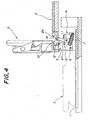
- Fig. 4 is a partially sectional side view showing an embodiment of the present invention in association with a specified deck.
- reference numeral 1 designates a lower stage-side deck arranged in the horizontal attitude, and 2 an upper side deck arranged in the horizontal attitude also, while the decks 1 and 2 taking the protracted attitude.
- Frames 4 are arranged on a rear end portion of each of the decks, i.e. the lower stage-side deck 1 in Fig. 4 so as to be positioned corresponding to chairs 3, respectively, and leg portions 5 of the chairs 3 is hinge-connected to the base frames 4, respectively, thereby enabling the leg portions 5, in its turn the chairs 3 to be rotated between the raised position shown by the actual line in Fig. 4 and the forward folded position shown by the imaginary line in Fig. 4.
- leg portion spring means e.g. a coil spring 7 for urging the leg portion 5 in the raised direction is connected to the leg portion 5 and the base frame 4, respectively.
- a stopper e.g. a bolt 8 is, as shown in Figs. 5(a) and 5(b), attached to the base frame 4 so as to protrude toward the leg portion, and a lock member, e.g. a horizontal rod 9 is fixed or secured to the leg portion 5, thereby enabling the horizontal rod 9 to abut against a front surface of the bolt 8, with the leg portion 5 taking the right raised attitude.
- a corner portion of a crank member 11 is rotatably supported, through a shaft 11, on a rear portion of the base frame 4 with respect to a hinge-connection position of the leg portion 5.
- the shaft 11 is penetrated through all the crank members on the same deck as a common shaft.
- this common shaft may not be a single shaft continuous over the whole length, and may consist of a plurality of shaft members connected to one another.
- each of the crank members 11 is provided with a swing arm 12 protruding from the base frame 4, and a hook 13 protruding from a lower end portion of the swing arm 12 forward, i.e. on a side of the leg portion, thereby enabling the hook 13 to be engaged with the horizontal rod 9 of the leg 5 which is in the raised attitude.
- the swing arm 12 has an upward protruding length as that its distal end portion abuts, as apparent from Fig. 4, against a front end surface 2a of the upper stage-side deck 2 when the hook 3 is engaged with the horizontal rood 9. More preferably, the distal end portion is rotatably attached with a roller 14, thereby decreasing a friction force between the swing arm 12 and the upper stage-side deck 2.
- auxiliary spring means e.g. an extension coil spring 15 for urging the swing arm 12 rearward
- the other end of the coil spring 15 is connected to the base frame 4.
- a rearward swing limit position of the swing arm 12 is specified by a notch end face 4b, as a positioning means, which is formed on a top wall 4a of the base frame 4, as shown in a perspective view of Fig. 5.
- the respective decks are retracted in the ascending order from the lowest stage-side with the chairs 3 maintained in the raised state, thereby causing the decks to be accommodated with the respective chairs 3 automatically folded forward.
- the chairs 3 are, according to the decks' retracting-displacement, automatically folded as follows:
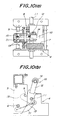
- Fig. 10 is a view showing another embodiment of the present invention. This embodiment is different from that of Fig. 5 in that a portion of the raised leg portion 5 below the hinge pin 6 is connected through a pressing link member 31 to a portion of the corner portion of the crank portion 10 opposite to the hook 13 with respect to the rotatably supporting shaft 11.
- the pressing link member 31 shown in the drawings is shaped like a slight curve protruding downward in order to prevent interference with the pin 6 and the shaft 11, and also has, e.g. an oblong hole, at a portion thereof connected to the crank member 10, for allowing the crank member 10 to slightly swing around the shaft 11 in order to ensure the hook 13 engaging to and disengaging from the horizontal rod 9.
- the extension coil spring 15 as auxiliary spring means for urging the swing arm 12 rearward is bridged between respective connecting pins of the pressing link member 31, thereby decreasing a required extending amount of the extension coil spring 15 compared with that of the above-mentioned embodiment.
- the swing arm 12 takes, also when the leg portion 5 and the chair 3 are perfectly folded, the raising attitude shown in Figs. 6(a), 8(d), etc., or the rearward inclined attitude.
- attaching arm guide means e.g. a guide rod 32, positioned corresponding to the swing arm 12, to the back surface of the upper stage-side deck 2 so as to extend in the longitudinal direction of the deck substantially eliminates the unevenness of the back surface of the deck, and hence, when the lower stage-side deck is entered into below the upper stage-side deck together with the chairs, etc. and protracted from below the upper stage-side deck, the guide rod 32 guides the movement of the distal end of the swing arm, which requires preventing the swing arm from unexpectedly abutting against the back surface of the deck.
- the construction shown in Fig. 10 eliminates, compared with the above case, the need for the design man-hours of determining the attaching position of the guide rod 32 and the man-hours of attaching the guide rod 32, and hence effectively reduces the weight of the deck, the cost, etc.
- leg portion 5 is raised by the worker applying an upward external force to the leg portion 5 taking the attitude shown in Fig. 11(b) to thereby rotate it, functioning the link member 31 as an tension member in this case to thereby displace the swing arm 12 together with the leg portion 5 in the raising direction, finally engaging the horizontal rod 9 to the hook 13 with leg portion 5 taking the perfect raised attitude shown in Fig. 10(b).
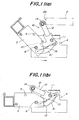
- Fig. 13 is a sectional side view of a main part of another embodiment.
- the link member is comprised of an tension link member 33, one end of which is connected to a portion of the leg portion 5, which is slightly above the pin 6 when the leg portion 5 takes the raised attitude, and the other end is connected to a portion of the crank member 10, which is on a side of the swing arm with respect to the rotatably supporting shaft 11.
- the extension coil spring 15 is connected to the corner portion of the crank member 10 and the base frame 4, respectively.
- the leg portion 5 which is in the perfect raised state as shown in Fig. 13(a), is folded by causing the distal end of the swing arm 12 to abut against the upper stage-side deck 2 as shown in Fig. 13(b), to thereby rotate the swing arm 12, preferably together with the rotatably supporting shaft 11, thereby causing the hook 13 to be separated from the horizontal rod 9, and continuously pressing the leg portion 5 through the swing arm 12.
- Such folding-displacement of the leg portion 5 causes the tension link member 33 to undergo a tension force, thereby causing the swing arm 12 to be folded in the same direction, which causes the swing arm 12 also to be maintained in the folded attitude when the leg portion 5 takes the perfect folded attitude as shown in Fig. 13(c).
- the leg portion 5 is raised by rotating the swing arm 12 also in the raising direction using the pressing function of the link member 33 exhibited when the leg portion 5 is rotated in the raised direction, and finally engaging the horizontal rod 9 to the hook 13 as shown in Fig. 13(a).
- Fig. 14 is a sectional side view of a main part of still another embodiment.
- a compression spring 34 as one example of spring means is connected, at one end thereof, to the corner portion of the crank member 10 opposite to the hook 13 and the swing arm 12 with respect to the rotatably supporting shaft 11 of the crank member 10, and connected to the base frame 4 at the other end thereof, which makes the spring 34 a so-called over center type of functioning as a compression spring even when a center line of the spring 14 is positioned at either sides of a center of the shaft 11 according to the rotation-displacement of the crank member 10. This causes the swing arm 12 to undergo a click movement in the raising direction and the folding direction.
- this construction is provided with positioning means, e.g. the notch end surface 4b of the base frame top wall 4a, described using Fig. 5(c), for restricting the rearward inclination position of the swing arm 12 in order to prevent the swing arm 12 from being excessively displaced in the raised direction.
- positioning means e.g. the notch end surface 4b of the base frame top wall 4a, described using Fig. 5(c)
- the raised direction-wise movement of the swing arm 12 is defined by abutment of the swing arm 12 or the crank member 10 to the leg portion 5, which eliminates the need for providing special positioning means.
- the leg portion 5 is folded as is the case with each of the above mentioned embodiments, the rotational movement of the swing arm 12 based on abutment of the swing arm 12 to the upper stage-side deck causes the hook 13 to be separated from the horizontal rod 9, and then the leg portion 5 to be folded, as shown in Fig. 14(b).
- the compression spring 34 is displaced in a direction opposite to that of the shaft 11 while being slightly compression-deformed in itself, thereby causing the swing arm 12 to be, when the leg portion 5 takes the perfect folded attitude shown in Fig. 14(b), urged in the raised direction.
- this raising and folding construction also is capable of sufficiently eliminating a fear that the distal end of the swing arm 12 abuts against the back surface of the upper stage-side deck, etc. without providing special arm guide means on the back surface of the upper stage-side deck.
- Fig 15 shows a case in which an extension spring 35 is used as the spring means.
- the point of application of force of the extension spring 35 is arranged on the crank member 10 at a side of the hook 13 and the swing arm 12 with respect to the rotatably supporting shaft 11 of the crank member 10, and also an escape piece 36 is interposed between the extension spring 35 and the point of application of force in order to prevent interference between the rotatably supporting shaft 11 and the extension spring 35.
- the above-mentioned spring 35 also functions as the so-called over center type spring as is the case with the above-mentioned compression spring 34, thereby causing the swing arm 12 to undergo a click movement. Also, selection of the point of application of force increases the engagement force between the hook 13 and the horizontal rod 9 when the leg portion 5 takes the raised attitude as shown in Fig. 15(a), and maintains the swing arm 12 in the folded state when leg portion 5 takes the folded attitude as shown in Fig. 15(b).
- the present invention provides a chair-raising and folding construction for a moving stand which is simple in construction, and reduced in weight and occupied space, and which is capable of, when using the moving stand with lower stages of decks protracted, effectively preventing spectators, etc. from entering into non-used decks protracted.
Landscapes
- Engineering & Computer Science (AREA)
- Architecture (AREA)
- Health & Medical Sciences (AREA)
- Dentistry (AREA)
- General Health & Medical Sciences (AREA)
- Civil Engineering (AREA)
- Structural Engineering (AREA)
- Chairs For Special Purposes, Such As Reclining Chairs (AREA)
Claims (8)
- Konstruktion zum Aufstellen und Zusammenklappen eines Stuhls für einen fliegenden Stand, bei dem man eine Anzahl vertikal beabstandeter waagrechter Bühnenebenen (1, 2) im Wesentlichen teleskopartig zusammen- und vorschieben kann und auf den Ebenen jeweils eine Anzahl aufstell- und zusammenklappbarer Stühle (3) sind , wobei
ein Beinteil (5) des Stuhls über ein Gelenk nach vorne zu einem auf der Ebene angeordneten Grundrahmen (4) klappbar ist,
ein Kurbelglied (10), umfassend einen Schwenkhebel (12), der nach oben aus dem Grundrahmen vorsteht, und einen Haken (13), der aus dem unteren Endabschnitt des Schwenkhebels (12) nach vorne vorsteht, drehbar auf einem rückwärtigen Bereich des Beinteils an einem Eckenabschnitt davon gehaltert ist,
der Schwenkhebel (12) eine solche vorstehende Länge besitzt, dass dessen entfernter Endbereich eine Stirnseite (89) der oberen bühnenseitigen Ebene (2) beanschlagt, dadurch gekennzeichnet, dass das Beinteil (5) mit einem Riegelglied (9) versehen ist, das mit dem Haken (13) eingreift, wenn das Beinteil (5) in aufrechter Stellung ist. - Konstruktion zum Aufstellen und Zusammenklappen eines Stuhls für einen fliegenden Stand nach Anspruch 1, wobei die Achsen (11) zum drehbaren Haltern der Kurbelglieder (10) am Grundrahmen als eine gemeinsame Achse aller Kurbelglieder, welche auf der gleichen Ebene angeordnet sind, ausgeführt ist.
- Konstruktion zum Aufstellen und Zusammenklappen eines Stuhls für einen fliegenden Stand nach Anspruch 1 oder 2, zudem umfassend eine Beinteil-Federeinrichtung (7) zum Drücken des Beinteils in die aufrechte Stellung und einen Stopper zum Verhindern, dass das Beinteil nach hinten geneigt ist.
- Konstruktion zum Aufstellen und Zusammenklappen eines Stuhls für einen fliegenden Stand nach einem der Ansprüche 1 bis 3, zudem umfassend eine Hilfsfedereinrichtung (15) zum Drücken des Schwenkhebels nach hinten und eine Positioniereinrichtungen zum Begrenzen der nach hinten geneigten Stellung des Schwenkhebels.
- Konstruktion zum Aufstellen und Zusammenklappen eines Stuhls für einen fliegenden Stand nach einem der Ansprüche 1 bis 3, wobei das Beinteil (5) und das Kurbelglied (10) miteinander verbunden sind über ein Bindeglied (31), welches den Schwenkhebel beim Zusammenklappen des Beinteils zwangsweise mit nach vorne klappt, wobei die Konstruktion Hilfsfedereinrichtungen (15) umfasst zum Drücken des Schwenkhebels nach hinten.
- Konstruktion zum Aufstellen und Zusammenklappen eines Stuhls für einen fliegenden Stand nach Anspruch 5, wobei das Bindeglied (31) ein drückendes oder elastisches Bindeglied umfasst.
- Konstruktion zum Aufstellen und Zusammenklappen eines Stuhls für einen fliegenden Stand nach einem der Ansprüche 1 bis 3, umfassend eine Art Federeinrichtung (34) zum Drücken des Schwenkhebels mit der Klapp- beziehungsweise der Aufstellverschiebung des Beinteils nach vorne oder hinten und Positioniereinrichtungen zum Begrenzen der nach hinten geneigten Stellung des Schwenkhebels.
- Konstruktion zum Aufstellen und Zusammenklappen eines Stuhls für einen fliegenden Stand nach Anspruch 7, wobei die Feder (34) eine anpressende oder eine elastische Feder ist.
Applications Claiming Priority (3)
| Application Number | Priority Date | Filing Date | Title |
|---|---|---|---|
| JP569998 | 1998-01-14 | ||
| JP569998 | 1998-01-14 | ||
| PCT/JP1998/003007 WO1999036645A1 (en) | 1998-01-14 | 1998-07-03 | Seat erecting/folding structure for movable spectators' stand |
Publications (3)
| Publication Number | Publication Date |
|---|---|
| EP0969166A1 EP0969166A1 (de) | 2000-01-05 |
| EP0969166A4 EP0969166A4 (de) | 2004-03-17 |
| EP0969166B1 true EP0969166B1 (de) | 2007-02-28 |
Family
ID=11618361
Family Applications (1)
| Application Number | Title | Priority Date | Filing Date |
|---|---|---|---|
| EP98929824A Expired - Lifetime EP0969166B1 (de) | 1998-01-14 | 1998-07-03 | Sitzaufbau und falteinrichtung für einen transportierbaren zuschauerplatz |
Country Status (6)
| Country | Link |
|---|---|
| US (1) | US6244657B1 (de) |
| EP (1) | EP0969166B1 (de) |
| JP (1) | JP3714968B2 (de) |
| DE (1) | DE69837196T2 (de) |
| ES (1) | ES2278413T3 (de) |
| WO (1) | WO1999036645A1 (de) |
Families Citing this family (32)
| Publication number | Priority date | Publication date | Assignee | Title |
|---|---|---|---|---|
| CA2323271A1 (en) * | 1999-10-15 | 2001-04-15 | Richard L. Patterson | Deployable bleacher/chair combination |
| US6484450B1 (en) * | 2000-11-09 | 2002-11-26 | Scott Suprina | Demountable indoor/outdoor seating system components |
| ES2200635B1 (es) * | 2001-04-27 | 2005-03-01 | Cecilia Vila Torra | Sistema automatico para levantar y/o abatir las butacas de cada una de las filas de las gradas de una tribuna telescopica. |
| AU2002342029A1 (en) | 2001-10-09 | 2003-05-06 | Flexible Seating Systems, Llc | Folding seat module system and method of using same |
| ES2200650B1 (es) * | 2001-10-26 | 2005-03-01 | Cecilia Vila Torra | Sistema de abatimiento de cada una de las filas de butacas de las gradas de una tribuna telescopica. |
| US6474024B1 (en) * | 2001-11-07 | 2002-11-05 | Macintyre James R. | Variable riser seating system |
| US7107724B2 (en) | 2002-03-19 | 2006-09-19 | Ri, Inc. | Interchangeable stadium seating and entertainment stage |
| US6925760B2 (en) | 2002-04-24 | 2005-08-09 | Scott Suprina | Stackable modular arena seating |
| ES1056003Y (es) * | 2003-11-05 | 2004-06-01 | Figueras Int Seating Sa | Disposicion perfeccionada de plegado en butacas. |
| US7303235B1 (en) * | 2004-01-20 | 2007-12-04 | Preferred Engineering | Chair for venues with tiered seating |
| US7337583B1 (en) | 2004-03-10 | 2008-03-04 | Irwin Seating Company | Extendable deck for seating system |
| US7267403B2 (en) * | 2004-03-11 | 2007-09-11 | Irwin Seating Company | Foldable bleacher seats |
| KR100751386B1 (ko) * | 2004-08-31 | 2007-08-22 | 주식회사 유니테크 시스템 | 보조관람석단을 갖는 수납식 관람석 |
| US20070200409A1 (en) * | 2006-02-28 | 2007-08-30 | Interkal, Llc | Forward folding seat assembly |
| US7617635B2 (en) * | 2007-02-14 | 2009-11-17 | Track Corp. | Multi-configurable platform seating system |
| CN101796254B (zh) | 2007-06-08 | 2012-12-05 | 斯蒂尔戴科工业有限公司 | 讲台及用于讲台的支撑结构 |
| CA2740563C (en) * | 2008-11-21 | 2017-09-12 | Gestion Laforest Inc. | Removable seats system |
| KR100919514B1 (ko) * | 2008-12-01 | 2009-09-28 | 주식회사대동이엔지 | 모바일 데크 지지장치 |
| US8438786B2 (en) * | 2009-07-23 | 2013-05-14 | Irwin Seating Company | Flexible venue system |
| ES2365342B1 (es) * | 2009-10-29 | 2012-05-08 | Sohosevilla, S.L. | Silla de cuatro patas paralelas plegable. |
| US8407943B2 (en) * | 2009-10-30 | 2013-04-02 | Irwin Seating Company | Bleacher seating system |
| US8544945B2 (en) * | 2010-06-04 | 2013-10-01 | The Product People Pty. Limited | Armrest construction and method |
| CN202269691U (zh) | 2011-04-25 | 2012-06-13 | 克斯克管理公司 | 折叠椅 |
| KR200471306Y1 (ko) * | 2011-05-13 | 2014-02-12 | 이낙철 | 의자 |
| US9115505B2 (en) * | 2011-07-22 | 2015-08-25 | Irwin Seating Company | Nosemount seating system |
| BE1020294A3 (nl) * | 2011-11-10 | 2013-07-02 | Cos Nv | Telescopische tribune met automatisch op-en neerklapbare stoelen. |
| EP2909397B1 (de) * | 2012-09-11 | 2020-05-06 | Steeldeck Industries Limited | Trägerstruktur für podium und stapelmethodthe hierfür |
| US9326610B2 (en) * | 2013-08-21 | 2016-05-03 | Frederick JACOBS | Telescopic seating systems, and foldable chairs and related components for use within telescopic seating systems |
| KR101510601B1 (ko) * | 2014-11-18 | 2015-04-20 | 주식회사 유니테크 시스템 | 관람석 다단 시스템 |
| CN105962668B (zh) * | 2016-06-23 | 2019-07-16 | 周云翔 | 一种活动看台座椅翻转装置 |
| US11035138B2 (en) * | 2018-11-02 | 2021-06-15 | Hussey Seating Company | Bleacher deck interlock apparatus and method |
| US11659929B2 (en) * | 2019-09-06 | 2023-05-30 | Hussey Seating Company | Double action nose mount quattro stanchion |
Family Cites Families (10)
| Publication number | Priority date | Publication date | Assignee | Title |
|---|---|---|---|---|
| US4211450A (en) * | 1979-04-05 | 1980-07-08 | Hussey Manufacturing Company, Inc. | Release mechanism for rows of collapsible seats |
| JPS60102468A (ja) * | 1983-11-07 | 1985-06-06 | 株式会社コトブキ | 伸縮式階段状観覧席の椅子起立転倒装置 |
| JPS62201109A (ja) | 1986-02-28 | 1987-09-04 | 株式会社コトブキ | 伸縮式階段状観覧席の椅子自動起立転倒装置 |
| JPH01142753A (ja) | 1987-11-30 | 1989-06-05 | Toshiba Corp | 現像装置 |
| JP2582387B2 (ja) | 1987-12-15 | 1997-02-19 | 富士通株式会社 | 半導体装置及びその試験方法 |
| JPH0427965Y2 (de) * | 1988-03-28 | 1992-07-06 | ||
| JPH01158753U (de) * | 1988-04-22 | 1989-11-02 | ||
| JP2778464B2 (ja) * | 1994-05-06 | 1998-07-23 | コクヨ株式会社 | 収納式椅子 |
| JP3309032B2 (ja) * | 1995-02-28 | 2002-07-29 | 株式会社コトブキ | 観覧席用シートおよび折り畳み式のシートを有する観覧席 |
| JP2948516B2 (ja) * | 1995-09-29 | 1999-09-13 | 株式会社コトブキ | 伸縮式階段状観覧席の起立転倒装置 |
-
1998
- 1998-07-03 EP EP98929824A patent/EP0969166B1/de not_active Expired - Lifetime
- 1998-07-03 ES ES98929824T patent/ES2278413T3/es not_active Expired - Lifetime
- 1998-07-03 WO PCT/JP1998/003007 patent/WO1999036645A1/ja not_active Ceased
- 1998-07-03 DE DE69837196T patent/DE69837196T2/de not_active Expired - Lifetime
- 1998-07-03 JP JP53699399A patent/JP3714968B2/ja not_active Expired - Lifetime
- 1998-07-03 US US09/380,960 patent/US6244657B1/en not_active Expired - Fee Related
Also Published As
| Publication number | Publication date |
|---|---|
| US6244657B1 (en) | 2001-06-12 |
| DE69837196T2 (de) | 2007-06-28 |
| JP3714968B2 (ja) | 2005-11-09 |
| DE69837196D1 (de) | 2007-04-12 |
| HK1024725A1 (en) | 2000-10-20 |
| ES2278413T3 (es) | 2007-08-01 |
| EP0969166A1 (de) | 2000-01-05 |
| WO1999036645A1 (en) | 1999-07-22 |
| EP0969166A4 (de) | 2004-03-17 |
Similar Documents
| Publication | Publication Date | Title |
|---|---|---|
| EP0969166B1 (de) | Sitzaufbau und falteinrichtung für einen transportierbaren zuschauerplatz | |
| US4475763A (en) | Rear seat arrangement for motor vehicle and the like | |
| US5580130A (en) | Seat for bleachers | |
| JPWO1999036645A1 (ja) | 移動観覧席の椅子の起立倒伏構造 | |
| DE69211651T2 (de) | Faltbarer Sitz | |
| MXPA00010591A (es) | Mesa plegable y transportable. | |
| US20260070769A1 (en) | Lift device | |
| CA2631395A1 (en) | Improvements in accessing an upper bed | |
| DE102004061852A1 (de) | Vorrichtung zum Umklappen eines Sitzes eines Fahrzeugs | |
| HK1024725B (en) | Seat erecting/folding structure for movable spectators' stand | |
| US5701826A (en) | Table for recreational vehicles | |
| US4702043A (en) | Apparatus for turning up and down seats for a telescopic seating system | |
| JP3992897B2 (ja) | 床下格納シート構造 | |
| US5513398A (en) | Futon tilt mechanism | |
| JPS646350Y2 (de) | ||
| KR102501858B1 (ko) | 확장 테이블이 구비된 캠핑 장치 | |
| JPH0354608Y2 (de) | ||
| JPH037218Y2 (de) | ||
| JPH0535003Y2 (de) | ||
| JP3547631B2 (ja) | 自動車のシート装置 | |
| JP7442981B2 (ja) | 荷受台昇降装置におけるストッパ装置 | |
| JP2597198Y2 (ja) | 椅子収納型床装置 | |
| KR20240113091A (ko) | 플랫 리어 시트 | |
| JP2602279Y2 (ja) | 車両の荷受台昇降装置 | |
| CN110883724A (zh) | 应用于后排座椅坐垫和靠背的在线可折叠装配夹具 |
Legal Events
| Date | Code | Title | Description |
|---|---|---|---|
| PUAI | Public reference made under article 153(3) epc to a published international application that has entered the european phase |
Free format text: ORIGINAL CODE: 0009012 |
|
| 17P | Request for examination filed |
Effective date: 19991006 |
|
| AK | Designated contracting states |
Kind code of ref document: A1 Designated state(s): DE ES FR GB |
|
| A4 | Supplementary search report drawn up and despatched |
Effective date: 20040130 |
|
| GRAP | Despatch of communication of intention to grant a patent |
Free format text: ORIGINAL CODE: EPIDOSNIGR1 |
|
| GRAS | Grant fee paid |
Free format text: ORIGINAL CODE: EPIDOSNIGR3 |
|
| GRAA | (expected) grant |
Free format text: ORIGINAL CODE: 0009210 |
|
| AK | Designated contracting states |
Kind code of ref document: B1 Designated state(s): DE ES FR GB |
|
| REG | Reference to a national code |
Ref country code: GB Ref legal event code: FG4D |
|
| REF | Corresponds to: |
Ref document number: 69837196 Country of ref document: DE Date of ref document: 20070412 Kind code of ref document: P |
|
| REG | Reference to a national code |
Ref country code: HK Ref legal event code: GR Ref document number: 1024725 Country of ref document: HK |
|
| ET | Fr: translation filed | ||
| REG | Reference to a national code |
Ref country code: ES Ref legal event code: FG2A Ref document number: 2278413 Country of ref document: ES Kind code of ref document: T3 |
|
| PLBE | No opposition filed within time limit |
Free format text: ORIGINAL CODE: 0009261 |
|
| STAA | Information on the status of an ep patent application or granted ep patent |
Free format text: STATUS: NO OPPOSITION FILED WITHIN TIME LIMIT |
|
| 26N | No opposition filed |
Effective date: 20071129 |
|
| PGFP | Annual fee paid to national office [announced via postgrant information from national office to epo] |
Ref country code: ES Payment date: 20080829 Year of fee payment: 11 |
|
| REG | Reference to a national code |
Ref country code: ES Ref legal event code: FD2A Effective date: 20090704 |
|
| PG25 | Lapsed in a contracting state [announced via postgrant information from national office to epo] |
Ref country code: ES Free format text: LAPSE BECAUSE OF NON-PAYMENT OF DUE FEES Effective date: 20090704 |
|
| PGFP | Annual fee paid to national office [announced via postgrant information from national office to epo] |
Ref country code: FR Payment date: 20110728 Year of fee payment: 14 |
|
| PGFP | Annual fee paid to national office [announced via postgrant information from national office to epo] |
Ref country code: DE Payment date: 20110729 Year of fee payment: 14 |
|
| REG | Reference to a national code |
Ref country code: FR Ref legal event code: ST Effective date: 20130329 |
|
| PG25 | Lapsed in a contracting state [announced via postgrant information from national office to epo] |
Ref country code: DE Free format text: LAPSE BECAUSE OF NON-PAYMENT OF DUE FEES Effective date: 20130201 Ref country code: FR Free format text: LAPSE BECAUSE OF NON-PAYMENT OF DUE FEES Effective date: 20120731 |
|
| REG | Reference to a national code |
Ref country code: DE Ref legal event code: R119 Ref document number: 69837196 Country of ref document: DE Effective date: 20130201 |
|
| PGFP | Annual fee paid to national office [announced via postgrant information from national office to epo] |
Ref country code: GB Payment date: 20170628 Year of fee payment: 20 |
|
| REG | Reference to a national code |
Ref country code: GB Ref legal event code: PE20 Expiry date: 20180702 |
|
| PG25 | Lapsed in a contracting state [announced via postgrant information from national office to epo] |
Ref country code: GB Free format text: LAPSE BECAUSE OF EXPIRATION OF PROTECTION Effective date: 20180702 |