EP0968498B1 - Anwenderspezifische graphiken für optische platten - Google Patents
Anwenderspezifische graphiken für optische platten Download PDFInfo
- Publication number
- EP0968498B1 EP0968498B1 EP98911794A EP98911794A EP0968498B1 EP 0968498 B1 EP0968498 B1 EP 0968498B1 EP 98911794 A EP98911794 A EP 98911794A EP 98911794 A EP98911794 A EP 98911794A EP 0968498 B1 EP0968498 B1 EP 0968498B1
- Authority
- EP
- European Patent Office
- Prior art keywords
- layer
- data
- disc
- image
- optical disc
- Prior art date
- Legal status (The legal status is an assumption and is not a legal conclusion. Google has not performed a legal analysis and makes no representation as to the accuracy of the status listed.)
- Expired - Lifetime
Links
- 230000003287 optical effect Effects 0.000 title claims description 106
- 239000002355 dual-layer Substances 0.000 title claims description 63
- 239000010410 layer Substances 0.000 claims description 257
- 238000002310 reflectometry Methods 0.000 claims description 35
- 230000002829 reductive effect Effects 0.000 claims description 19
- 239000011241 protective layer Substances 0.000 claims description 14
- 239000000758 substrate Substances 0.000 description 16
- 230000036961 partial effect Effects 0.000 description 13
- 238000000034 method Methods 0.000 description 12
- 239000000463 material Substances 0.000 description 10
- 239000000853 adhesive Substances 0.000 description 7
- 230000001070 adhesive effect Effects 0.000 description 7
- 230000009977 dual effect Effects 0.000 description 6
- 239000004922 lacquer Substances 0.000 description 6
- 229920002120 photoresistant polymer Polymers 0.000 description 6
- 238000002372 labelling Methods 0.000 description 5
- 239000011521 glass Substances 0.000 description 4
- 230000001427 coherent effect Effects 0.000 description 3
- 230000001419 dependent effect Effects 0.000 description 3
- 230000000737 periodic effect Effects 0.000 description 3
- 229920000515 polycarbonate Polymers 0.000 description 3
- 239000004417 polycarbonate Substances 0.000 description 3
- VYZAMTAEIAYCRO-UHFFFAOYSA-N Chromium Chemical compound [Cr] VYZAMTAEIAYCRO-UHFFFAOYSA-N 0.000 description 2
- 229910052782 aluminium Inorganic materials 0.000 description 2
- XAGFODPZIPBFFR-UHFFFAOYSA-N aluminium Chemical compound [Al] XAGFODPZIPBFFR-UHFFFAOYSA-N 0.000 description 2
- 230000002238 attenuated effect Effects 0.000 description 2
- 238000006243 chemical reaction Methods 0.000 description 2
- 239000011248 coating agent Substances 0.000 description 2
- 238000000576 coating method Methods 0.000 description 2
- 238000010586 diagram Methods 0.000 description 2
- 238000001746 injection moulding Methods 0.000 description 2
- 229910052751 metal Inorganic materials 0.000 description 2
- 239000002184 metal Substances 0.000 description 2
- 238000000465 moulding Methods 0.000 description 2
- 230000001681 protective effect Effects 0.000 description 2
- 230000002441 reversible effect Effects 0.000 description 2
- 239000002356 single layer Substances 0.000 description 2
- 125000006850 spacer group Chemical group 0.000 description 2
- 239000010409 thin film Substances 0.000 description 2
- 239000012790 adhesive layer Substances 0.000 description 1
- 239000003086 colorant Substances 0.000 description 1
- 230000008878 coupling Effects 0.000 description 1
- 238000010168 coupling process Methods 0.000 description 1
- 238000005859 coupling reaction Methods 0.000 description 1
- 230000006870 function Effects 0.000 description 1
- PCHJSUWPFVWCPO-UHFFFAOYSA-N gold Chemical compound [Au] PCHJSUWPFVWCPO-UHFFFAOYSA-N 0.000 description 1
- 229910052737 gold Inorganic materials 0.000 description 1
- 239000010931 gold Substances 0.000 description 1
- 239000010453 quartz Substances 0.000 description 1
- VYPSYNLAJGMNEJ-UHFFFAOYSA-N silicon dioxide Inorganic materials O=[Si]=O VYPSYNLAJGMNEJ-UHFFFAOYSA-N 0.000 description 1
Images


Classifications
-
- G—PHYSICS
- G11—INFORMATION STORAGE
- G11B—INFORMATION STORAGE BASED ON RELATIVE MOVEMENT BETWEEN RECORD CARRIER AND TRANSDUCER
- G11B7/00—Recording or reproducing by optical means, e.g. recording using a thermal beam of optical radiation by modifying optical properties or the physical structure, reproducing using an optical beam at lower power by sensing optical properties; Record carriers therefor
- G11B7/24—Record carriers characterised by shape, structure or physical properties, or by the selection of the material
- G11B7/24094—Indication parts or information parts for identification
-
- G—PHYSICS
- G11—INFORMATION STORAGE
- G11B—INFORMATION STORAGE BASED ON RELATIVE MOVEMENT BETWEEN RECORD CARRIER AND TRANSDUCER
- G11B23/00—Record carriers not specific to the method of recording or reproducing; Accessories, e.g. containers, specially adapted for co-operation with the recording or reproducing apparatus ; Intermediate mediums; Apparatus or processes specially adapted for their manufacture
- G11B23/38—Visual features other than those contained in record tracks or represented by sprocket holes the visual signals being auxiliary signals
- G11B23/40—Identifying or analogous means applied to or incorporated in the record carrier and not intended for visual display simultaneously with the playing-back of the record carrier, e.g. label, leader, photograph
-
- G—PHYSICS
- G11—INFORMATION STORAGE
- G11B—INFORMATION STORAGE BASED ON RELATIVE MOVEMENT BETWEEN RECORD CARRIER AND TRANSDUCER
- G11B7/00—Recording or reproducing by optical means, e.g. recording using a thermal beam of optical radiation by modifying optical properties or the physical structure, reproducing using an optical beam at lower power by sensing optical properties; Record carriers therefor
- G11B7/24—Record carriers characterised by shape, structure or physical properties, or by the selection of the material
- G11B7/26—Apparatus or processes specially adapted for the manufacture of record carriers
- G11B7/261—Preparing a master, e.g. exposing photoresist, electroforming
-
- G—PHYSICS
- G11—INFORMATION STORAGE
- G11B—INFORMATION STORAGE BASED ON RELATIVE MOVEMENT BETWEEN RECORD CARRIER AND TRANSDUCER
- G11B7/00—Recording or reproducing by optical means, e.g. recording using a thermal beam of optical radiation by modifying optical properties or the physical structure, reproducing using an optical beam at lower power by sensing optical properties; Record carriers therefor
- G11B7/24—Record carriers characterised by shape, structure or physical properties, or by the selection of the material
- G11B7/2403—Layers; Shape, structure or physical properties thereof
- G11B7/24035—Recording layers
- G11B7/24038—Multiple laminated recording layers
Definitions
- the present invention relates generally to optical discs.
- the present invention includes a dual layer optical disc having images within a diffraction pattern encoded in one or more layers in the disc.
- Optical discs such as CD-ROM (Compact Disc-Read Only Memory) or DVD (Digital Versatile Disc or Digital Video Disc) media have data stored as a series of lower reflectance "pits" formed within a plane of higher reflectance "lands".
- the pits may be coated with the same material as the lands, but due to pit geometry, will diffract more light than the flatter lands, and therefore return less light to the reading sensor.
- the pits bottoms may be illuminated and read resembling bumps, which also diffract more light than the flatter lands.
- the pits are arranged in a spiral track originating at the disc center hub and ending at the disc outer rim.
- the data may be considered to lie in a series of tracks spaced radially from the center hub.
- Disc layers having no data thereon may contain a spiral groove or a series of concentric grooves, creating a diffraction pattern. Whether a spiral or a series of concentric grooves, the resulting grooves are substantially
- the track typically begins in a "pre-user data" area near the center hub.
- the pre-user area contains descriptor information of the disc itself.
- a "user-data” area follows the pre-user data area, and contains the data of the disc.
- a "lead-out” area follows the user-data area, lying closer to the outer edge of the disc.
- the lead-out area contains no user data, but may contain a pattern of pits which can be a repeating pattern or a random pattern having no data readout value or information content.
- the pre-user data area, user-data area, and lead-out area collectively comprise the "information area" of the disc.
- the information content is encoded in the length of the slightly arcuate, circumferential pits.
- the track consists of a series of pits.
- the aligned pits appear to form a continual groove, with the spiral groove forming a diffraction pattern.
- the diffraction pattern reflects light of varying colors, as described by Bragg's law.
- the spiral track may be a continuous spiral groove, having a very long pit, formed not for information content but for appearance.
- the optical disc may contain a spiral pattern to the outer rim, there may be very little user-data present, with the lead-out area comprising a majority of the disc surface in a sparsely populated disc. In even a fully populated disc, the lead-out area comprises a few millimeters near the outer rim.
- a master optical disc is typically manufactured by coating a glass substrate with a positive photosensitive layer, followed by baking the coated substrate.
- a laser is thereafter used to expose portions of the photoresist in a spiral pattern of circumferential arcs of varying length, corresponding to the later formed pits.
- the master disc is thereafter developed, with the exposed areas being washed away, forming pits. The unexposed areas remain, forming a plane of higher "lands.” As such, the master disc is said to be "pre-recorded" optical disc.
- the master disc is used as a mold to form one or more harder, metallised, "stampers", having bumps corresponding to the pits in the master disc.
- the stampers are used to form the optical discs via injection molding, the final discs having pits corresponding to the bumps in the stampers corresponding to the pits in the master disc.
- the readable side includes a transparent polycarbonate bottom layer having the reflective layer thereover, which in turn has a protective "lacquer" layer thereover, which can include a label.
- the readable side is typically placed face down over a laser reader which penetrates the transparent layer to the single reflective layer having pits.
- pits are formed in such a way to give a high contrast signal relative to the land.
- DVDs are optical discs having increased capacity relative to CD-ROMs. In one example, this is achieved in part by having double sided discs. Double sided DVDs have two reflective layers, each facing outward, requiring flipping the disc to read both sides or an additional device to read the second side.
- Double sided DVDs require each side to be transparent, and thus have a special labelling requirement, as covering one side with lacquer and label is no longer possible. Any label or image on the disc must be both visible, and transparent to a laser in the region containing data. Double sided discs consist of two single sided discs bonded back to back with an adhesive.
- Dual layer discs include an innermost data layer having a reflective layer thereon, and an outermost data layer having a reflective layer thereon.
- the outermost reflective layer is sometimes referred to as the "semi-reflective layer” and the innermost reflective layer as the "fully reflective layer”.
- the outermost reflective layer has optically readable differences in reflectivity between lands and pits, yet being sufficiently transparent to allow reading of the innermost reflective layer below.
- the desired innermost or outermost layer is optically read by focusing the optical disc reader at the proper depth for the layer of interest.
- dual layer optical discs may also be double sided.
- a double-sided, dual layer optical disc includes two optically readable layers on each side of the disc.
- Labelling of the previously described optical discs is important. Labelling can operate as a deterrent to piracy.
- the data on optical discs, being digital, can be read perfectly, and reproduced perfectly, in unlimited quantities.
- Standard labels on the lacquer side of CD-ROMs can also easily be reproduced, using techniques similar to those used to produce the original labels. Labelling requiring the creation of art-work on the master discs or stampers themselves would require significantly more effort and/or specialized equipment to produce copies capable of passing as the original discs.
- the present invention is a dual layer optical disc having optically viewable images encoded on selected layers of the disc.
- the invention may include a double sided disc, where each side can have images encoded therein.
- the present invention as defined in claim 1 includes a dual layer optical disc having images encoded therein.
- the dual layer optical disc includes a first data layer and a second data layer coupled to the first data layer.
- An optically viewable image is encoded within the first data layer.
- a second optically viewable image may be encoded within the second data layer.
- the first data layer having an optically viewable image therein, may include a data region and an image region, each region having a plurality of lands and pits.
- the lands in the image region may have a height less than the height of the lands located within the data region relative to the pits.
- the dual layer optical disc may further include optically readable data encoded within the second layer and/or first layer.
- the optically viewable image may be a light contrast image, a medium contrast image, or heavy contrast image. If the optically viewable image is a light contrast image, the optically viewable image may further include optically readable data encoded therein.
- the optically viewable image may be a holographic image.
- the first data layer and the second data layer may have a balanced reflectivity value. In another application, the first data layer and the second data layer may have an unbalanced reflectivity value. In one preferred embodiment, the first data layer is semi-reflective and the second data layer is reflective.
- the dual layer optical disc may further include a second side, having a third data layer and a fourth data layer.
- the third data layer or the fourth data layer may also include an optically viewable image encoded therein.
- the present invention includes a dual layer optical disc having an image encoded therein.
- the dual layer optical disc includes a first protective layer and a first layer, the first layer including a first data layer having a first reflective layer formed thereover.
- a second layer is interposed between the first protective layer and the first layer, including a second data layer having a second reflective layer formed thereover.
- An optically viewable image may be encoded within the first layer or the second layer.
- the first layer and the second layer may have a balanced reflectivity value. In another application, the first layer and the second layer may have an unbalanced reflectivity value. In one embodiment, the first reflective layer is semi-reflective and the second reflective layer is reflective.
- the dual layer optical disc in accordance with the present invention may further include a third layer including a third data layer having a third reflective layer formed thereover, wherein the first protective layer is formed of an adhesive and couples the second layer to the third layer.
- An optically viewable image may be encoded within the third layer.
- a fourth layer may be coupled to the third layer, the fourth layer including a fourth data layer having a fourth reflective layer formed thereover.
- dual-layer optical discs are used in the exemplary embodiments described herein, it is recognized that the field to which this invention pertains includes all types of dual-layer optical data discs having information contained in data structures therein as data features.
- the data features may include data pits, grooves, bumps or ridges, and lands or land areas. This includes current formats of dual layer DVD, as well as future formats which use data features described herein.
- Figure 1 illustrates a readable side of a dual layer optical disc 20 having an image 22 located therein, in accordance with the present invention.
- the side shown is capable of being illuminated and read by an optical disc laser or reader.
- Disc 20 is a dual layer optical disc, such as a dual layered DVD optical disc.
- the opposite side (not shown in Figure 1) may be either an opaque, labeled, non-read side, or a second, readable side which also may be dual layered.
- Disc 20 includes an inner rim 23, an inner annular ring 24, an information area 25, an outer annular ring 32, and an outer rim 34.
- each layer may include an information area 25.
- the information area 25 is defined as the area on the disc 20 capable of containing user data.
- the information area 25 includes a pre-user data area 26, a user-data area 28, and a lead-out area 30.
- the pre-user data area 26 typically contains information about the disc contents, such as descriptive information.
- the user-data area 28 contains the user accessible contents of the disc.
- the lead-out area 30 typically appears as a spiral track similar to that in the user-data area, but may contain no information readable by an optical disc player.
- the information area 25 is the area available for information storage, even though much of it may be taken up with the lead-out area 30 when the disc has little user-data encoded.
- the information area 25 contains image 22, such as the Imation logo shown consisting of a design and alphanumeric characters. As shown, the image 22 is located in the lead-out area 30 of the information area 25.
- each layer of the dual layer disc has a pre-user data area 26, a user-data area 28 and a lead-out area 30.
- the disc reader begins reading the first layer pre-user data area 26, then reads the user-data area 28, and then travels from the lead-out area 30 to the second layer pre-user data area 26, and then reads the user-data area 28 of the second layer.
- the first layer has a pre-user data area 26 and a user-data area 28, and the second layer has a user-data area 28 and a lead-out area 30.
- the optical disc reader reads the first layer pre-user data area 26 and the user-data area 28, and then continues to the second layer and reads the user-data area 28 and ends at the lead-out area 30.
- FIGS. 2-17 illustrate different embodiments of a dual layer disc in accordance with the present invention having an image contained (encoded) on one of the layers therein. Each of these embodiments will be discussed in detail in the following paragraphs.
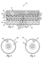
- disc 20 is a single-sided dual layer optical disc.
- Dual layer optical disc 20 includes a read side 40 and a non-read side 41. Starting at read side 40, the optical disc 20 further includes a first layer 42 having a first data layer 44 and a first reflective layer 46, and a second layer 43 having a second data layer (or spacer layer) 48 and a second reflective layer 50, and a protective layer 52.
- the first reflective layer 46 is interposed between the first data layer 44 and the second data layer 48
- the second reflective layer 50 is interposed between the second data layer 48 and the protective layer 52.
- the first data layer 44 and the second data layer 48 are generally transparent and include a series of lands 54 and pits 56.
- the first data layer 44 and the second data layer 48 are formed of a generally clear material.
- the first data layer 44 may be formed of a substantially clear polycarbonate and the second data layer 48 may be formed of a substantially clear photopolymer.
- the first reflective layer 46 and the second reflective layer 50 are formed of a reflective material, such as aluminum, gold, or a dielectric, such as is described in U.S. Patent No. 5,540,966, entitled "Dual Layer Optical Medium Having Partially Reflecting Thin Film Layer", issued July 30, 1996, having varied degrees of reflectivity, as will be described in detail later herein.
- the protective layer 52 may be formed of a protective material, such as lacquer, which may be opaque or clear. If the lacquer is clear, and no label is contained on non-read side 42, the reverse of image 22 may be viewed through the non-read side 42.
- the first layer 42 has data encoded therein, indicated by data region 58.
- the second layer 43 may also have data encoded therein, indicated by data region 60, but also includes image region 62.
- the data region 58 includes a series of full height lands 54 and pits 56.
- the data region 60 includes full height lands 54 and pits 56.
- the lands are reduced height lands 64. If a reference plane were drawn through the bottoms of the pits 56, the reduced height lands 64 appear reduced in height relative to full height lands 54. Reducing the difference in the height between reduced height lands 64 and full height lands 54, disturbs the periodic diffraction grating within image region 62, creating optically viewable image 22.
- the reduced height lands 64 within image region 62 produce a contrast in the diffraction grating between the image region 62 and the data region 60.
- the contrast in the diffraction grating within image region 62 results in a viewable image within the disc substrate, such as image 22.
- the image 22 can be a low contrast, medium contrast, or high contrast image. Whether the image 22 is a low contrast, medium contrast or high contrast image depends greatly upon the height of the reduced height lands 64 within image region 62 relative to the level of the pits 56 and the (full height) lands 54 within data region 58, and the reflectivity values of each layer (42 and 48).
- reduced height lands 64 are shorter than lands 54, relative to the bottom of pits 56, being reduced sufficient enough to create a viewable image, but not sufficient to destroy optical readability. Therefore, a light contrast image may be located within image region 62 using reduced height lands 64, yet reduced height lands 64 have a height sufficient to contain encoded data which is readable by an optical disc reader.
- image region 62 For heavy contrast images within image region 62, the lands are substantially or totally removed to the level of the bottom of the pits 56. The resulting difference in the diffraction pattern between image region 62 and data region 60 is a high contrast image located in image region 62.
- reduced height lands 64 are totally obliterated or substantially removed to form a high contrast image, no data may be encoded within the image region 62 which could be readable by an optical disc reader. As such, image region 62 can be said to be optically viewable, but not optically readable.
- a medium contrast image is produced using reduced height lands 64 having a medium height (as shown in Figure 2) within image region 62.
- a medium height land is a land having a height which can be defined within the range between where the height of the land is such that the image region 62 may be no longer readable by an optical disc reader when data is encoded therein, down to the point where the lands are substantially or completely removed or obliterated.
- the resulting difference in diffraction pattern between the image region 62 and data region 60 is a medium contrast image relative to the previously defined light contrast and heavy contrast images.
- data may be encoded within first layer 42 and images may be encoded in second layer 43.
- the images on second layer 43 may be light contrast, medium contrast or heavy contrast images.
- data may be encoded within first layer 42, and data may also be encoded within data region 60 of second layer 43, with light contrast, medium contrast or heavy contrast images encoded within image region 62. If the images encoded within image region 62 are light contrast images due to the height of the reduced height lands 64, then data may also be encoded within image region 62 which is not only optically viewable, but optically readable by an optical disc reader.
- Optical disc 20 has an effective reflectivity value, substantially caused by the reflectivity of first reflective layer 46 and second reflective layer 50, but also affected by the reflectivities and losses caused by the passage of light through the various substrates, including first data layer 44 and second data layer 48.
- First layer 42 has an effective reflectivity, indicated as R1, which is defined by the fraction or intensity of incident light that is reflected by first reflective layer 46 to a receiver (not shown) outside of first read side 40.
- the second reflective layer 50 has an effective reflectivity, indicated by R2, which may be defined as the fraction of incident light that is reflected by the second reflective layer 50 to a receiver (not shown) outside of first read side 40.
- the effective reflectivity values R1 and R2 are also affected by the various substrates which hight passes through.
- FIG 2 one exemplary embodiment of the attenuation of light (or signal) caused by first layer 42 and second layer 43 is shown.
- Incident light (70) enters first data layer 44, becoming attenuated (at 72) by surface reflection (not shown) at first data layer 44.
- the light is further attenuated as it passes through first data layer 44, and is reflected on first reflective layer 46 (74).
- the light reflected by the first reflective layer 46 again exits the first data layer 44 (76), which has been previously referred to as R1.
- the effective reflectivity of the first layer 42 and the second layer 43 may be balanced or unbalanced.
- R1 is equal to R2.
- Reflectance of the disc 20 materials are selected such that the resulting signal effective reflectivity value (or signal strength) of R1 is equal to R2.
- R1 is greater than R2 or R2 is greater than R1.
- An unbalanced effective reflectivity value may be desirable when other factors are considered, such as the desired visibility of an image encoded within one of the layers.
- the first reflective layer 46 is "semi-reflective" being formed of a metal or dielectric, such as those previously described herein, having a reflectivity rating in the range of 25 percent to 40 percent.
- the second reflective layer 50 is reflective, and may also be formed of a metal or dielectric having a greater reflectivity than first reflective layer 46. In one embodiment, the reflective layer 50 may have a reflectivity rating of 70 percent or greater and may be aluminum.
- the effective reflectivity value of the first layer 42 is not equal to the effective reflectivity value of the second layer 43 (for example, R1 is not equal to R2).
- the effective reflectivity value of the first reflective layer 46 is less than the effective reflectivity value of the second reflective layer 50, resulting in R1 less than R2.
- the ratio of R2 to R1 may be two to one or ten to one. It is also recognized that R1 may be greater than R2.
- first layer R1 may be varied to make images contained/encoded in one layer more visible or viewable than the other layer.
- data is encoded in first layer 42 and image 22 is encoded within second layer 43.
- First data layer 44, second data layer 48, and protective layer 52 are substantially clear.
- First reflective layer 46 is less reflective than second reflective layer 50, and in combination with other disc materials, results in an unbalanced reflectivity of R1 less than R2.
- Figure 3 is a plan view of optical disc 20 when viewed from the non-read side 41. Since protective layer 52 is substantially clear, image 22 may be viewed from the non-read side.
- a plan view of the optical disc 20 is shown, as viewed from the read side 40. Since the effective reflectivity value of first layer 42 (R1) is less than the effective reflectivity value of second layer 43 (R2), the image 22 may also be viewed from the read side 40.
- the diffraction grating contrast of image 22 when viewed from read side 40 is dependent upon the height of reduced height lands 64, as previously described herein, and is further dependent upon the difference in the reflectivity of the first layer 42 and the second layer 43.
- First layer 42 includes data region 58 and image region 62, having reduced height lands 64 for producing image 22.
- Second layer 43 includes data region 60 having data encoded therein. Similar to the previous embodiment, the first data layer 44, the second data layer 48, and the protective layer 52 are substantially clear. Further, the first layer 42 and the second layer 43 have an unbalanced reflectivity rating, wherein the first reflective layer 46 is less reflective than the second reflective layer 50.
- a plan view of dual layer optical disc 20 is shown as viewed from the non-read side 41. It is noted that since image 22 is contained within first layer 42, and the first reflective layer 46 is semi-reflective and the second reflective layer 50 is reflective, no change in diffraction grating is visible from the non-read side 41 and image 22 is not viewed.
- a plan view of dual layer optical disc 20 is shown as viewed from the read side.
- Image 22 located within first layer 42 is visible from the read side 40.
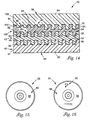
- first layer 42 and second layer 43 include visible (optically viewable) images thereon.
- second layer 43 includes reduced height lands 64 in image region 62 to disturb the periodic diffraction grating, creating the optically viewable image 22.
- First layer 42 includes reduced height lands 64 within image region 62 to disturb the periodic diffraction grating, creating an optically viewable alphanumeric image 90.
- image 22 or image 90 are a light contrast image resulting from the height of reduced height lands 64, optically readable data may also be encoded therein.
- first data layer 44, second data layer 48 and protective layer 52 are substantially clear. Further, the effective reflectivity of first layer 42 and second layer 43 is "unbalanced". Specifically, first layer 42 is semi-reflective and second layer 43 is reflective.
- a plan view of dual layer optical disc 20 is shown as viewed from non-read side 41. Since second layer 43 is reflective, only image 22 contained in second layer 43 is visible from the non-read side 41.
- a plan view of optical disc 20 is shown as viewed from the read side. In this view, alphanumeric image 90 contained within first layer 42 is visible. Further, since first layer 42 is semi-reflective and second layer 43 is reflective, the reverse of image 22 is also visible from the read side 40.
- Optical disc 20 includes first side 92, as previously described in detail in the embodiment of Figure 8, and also includes a second side 94.
- Second side 94 includes a read side 96 and a non-read side 98.
- second side 94 merely consists of a substrate formed of a material which can be similar to first data layer 44, such as a polycarbonate.
- the first side non-read side 41 is securely coupled to the second side non-read side 98 using protective layer (or coating) 52, which in this embodiment is preferably a clear adhesive.
- a plan view of optical disc 20 is shown as viewed from the second side 94 read side 96. Similar to Figure 9, only the diffraction grating resulting in image 22 is visible therein.
- a plan view of optical disc 20 is shown as viewed from the first side read side 40. Similar to Figure 10, both the image 22 and the alphanumeric image 90 are visible therein.
- first side 92 can be similar to the dual layer optical disc 20 as previously described herein.
- Second side 94 has an image 22 encoded therein.
- second side 94 further includes a third layer 100, including a third data substrate 102 and a third reflective layer 104.
- the third data substrate 102 and third reflective layer 104 may be formed of materials as previously described herein for first side 92.
- the first side 92 is coupled to second side 94 at protective layer 52, which may be an opaque adhesive.
- a plan view of optical disc 20 is shown as viewed from first side 92 read side 40. In this embodiment, image 22 is not visible from first side 92 read side 40.
- a plan view of optical disc 20 is shown as viewed from second side read side 96. As shown, the contrast in the diffraction grating between image region 62 and data region 106, results in an optically viewable image 22.
- First side 92 functions as a data side having optically readable data encoded within first layer 42 and second layer 43.
- Second side 94 operates as a label side, having image 22 in the form of a disc content label.
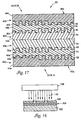
- FIG 17 a partial cross-sectional view of another embodiment of the optical disc 20 in accordance with the present invention is shown, wherein the optical disc 20 is a dual layer double-sided disc, wherein each side includes a dual layer. As shown, the optical disc 20 includes side A and side B, wherein each side includes images and data encoded within a layer therein.
- Each side, side A and side B can be similar to any of the dual layer optical disc embodiments as previously described herein.
- side A and side B are each similar to the embodiment of Figure 8, having both data and images encoded within each layer therein.
- the dual layer dual-sided optical disc 20 is formed by coupling two dual layer optical discs together, back to back, with an opaque adhesive 52.
- FIG 18 a process of creating a master disc 100 for use in creating a dual layer optical disc 20 in accordance with the present invention is shown.
- the process includes providing a substrate 102 coated with a photosensitive layer 104.
- the photosensitive layer 104 may be secured to the substrate 102 using an adhesive (not shown).
- the photosensitive layer 104 is responsive to a light source.
- the substrate 102 is formed of quartz or glass and the photosensitive layer 104 is formed of photoresist.
- a mask 106 is placed over and parallel to the plane of the photosensitive layer 104.
- the mask 106 may include a chrome pattern on a glass substrate.
- the glass substrate has an absence of chrome corresponding to the desired pattern.
- the mask 106 is a diffraction mask having an image pattern located therein to create a diffraction pattern disturbed in image regions within the photosensitive layer 104.
- a light source 108 is used for transferring the mask 106 pattern to the master disc 100.
- the light source 108 is a UV light source.
- the pattern mask 106 is positioned between the master disc 100 and the light source 108.
- the light source 108 emitting light 110 is placed over the pattern mask 106, and photosensitive layer 104 is exposed to the light 110 for a period of time sufficient to create the desired reaction.
- the amount of exposure reaction is dependent upon the light source intensity and the duration of the exposure of the photosensitive layer 104 to the light source 108.
- the master disc 100 is a pre-recorded master, meaning it has user-data already encoded on the disc.
- the master disc 100 is pre-recorded using a laser beam writer to record data by exposing photoresist in regions corresponding to future data pits as is well known in the art.
- both user-data, diffraction patterns and images may be developed in a development step.
- master disc 100 may not be previously recorded, and may have pre-user data and user-data portions encoded using a mask similar to mask 106, but encoding data pits in addition to the diffraction pattern.
- a laser beam is not required to either write data or form images on the disc.
- a laser beam may be used for recording images within the photosensitive layer 104 by exposing the photosensitive layer 104 in regions corresponding to the image regions. If a laser beam writer is utilized, the light source 108 and mask 106 are not necessary for forming images within photosensitive layer 104.
- light exposure region 114 is shown, which would correspond to a light contrast image being formed within one layer of optical disc 20.
- a medium exposure is shown, resulting in a medium contrast image in optical disc 20.
- a heavy exposure is shown, resulting in a heavy contrast image viewable within optical disc 20.
- the master disc 100 is used to form a metallized stamper to form a single layer of the dual layer disc in a disc molding process.
- the stamper will have ridges or stamper bumps corresponding to the pits within master 100.
- the stamper will be used to produce replica discs in an injection molding process.
- the replica disc may be used for making single sided dual layered discs or dual sided dual layered discs, such as shown in Figures 1-17.
- the first reflective layer 46 is deposited on the first data layer 44 to form first layer 42.
- the first layer 42 is coated with an embossable material, such as a photopolymer, and the data regions or image regions of the second data layer 48 are embossed within the embossable material.
- a second reflective layer 50 is deposited on the second data layer 48 to form the second layer 43.
- the second layer 43 is then covered with a protective layer 52, such as lacquer.
- a similar process is used for forming a second molded layer containing the second data layer 48 therein.
- a first reflective layer 46 is deposited on the first data layer 44, and a second reflective layer 50 is deposited on a second molded data layer.
- the first molded layer 42 and the second molded layer are secured together using a clear adhesive layer, which becomes the second data or spacer layer 48.
- individual dual layer discs or a dual layer disc and a single layer disc are coupled back to back using an adhesive, as previously indicated herein.
- the image encoded within one of the layers of the dual layer disc may be a holographic image.
- the holographic image may be formed in a master disc for creating a dual layer disc using methods as disclosed in U.S. Patent No. 5,607,188, previously incorporated herein by reference.
- a holographic image is produced in a layer of a dual layer optical disc, as previously described herein, using a coherent light source and a phase altering mask.
- the light source 108 is a coherent light source, such as a laser light.
- Mask 106 is a phase altering mask such as a holographic thin film phase grating.
- a hologram is formed on the master disc 100 when light from the phase altering mask 106 is interfered with non-defracted light that passes through the phase altering mask 106.
- the master disc 100 is developed and processed using methods as previously described herein, and contains a holographic image therein.
- a reflective object 130 is used to form the holographic image in the master disc 100.
- a reflective hologram 132 such as a Denisyuk hologram, is placed adjacent the master 100 (containing photoresist layer 104 over substrate 102) with the reflective side of the reflective hologram facing the photoresist layer 104.
- a coherent light source 134 such as a laser light is passed through the master 100 from the side opposite the photoresist layer 104. Laser light (indicated at 136) which passes through the master disc 100 will interfere with light reflected from the hologram 132 (indicated at 138), which will duplicate the reflective hologram on the master disc 100 (photosensitive layer 104).
- the master disc 100 is then developed as previously described herein, and contains a holographic image therein.
- the master disc 100 is used for making a dual layer optical disc with a holographic image encoded in at least one of the layers therein, as shown in the embodiments of Figures 1-17.
- any reflective object may be positioned adjacent the master disc 100 photosensitive layer 106 such that the light reflected from the object will duplicate the reflective object onto the master disc 100.
Claims (9)
- Optische Zweischichtplatte (20) mit einem darin codierten Bild (22), wobei die optische Zweischichtplatte aufweist:eine erste Datenschicht (44) mit mehreren Stegen (54) und mehreren Pits (56), und eine erste reflektierende Schicht (46);eine zweite Datenschicht (48), die mit der ersten Datenschicht gekoppelt ist und die gleiche Orientierung wie die erste Datenschicht hat, wobei die zweite Datenschicht mehrere Stege (54) und mehrere Pits (56) hat, und eine zweite reflektierende Schicht (50), und wobei die erste Datenschicht einen ersten Effektivwert für das Reflexionsvermögen hat und die zweite Datenschicht einen zweiten Effektivwert für das Reflexionsvermögen hat; undein optisch wahrnehmbares Bild (22), das in der ersten Datenschicht codiert ist, wobei das optisch wahrnehmbare Bild durch eine Region in der ersten Datenschicht mit höhenreduzierten Stegen (64) gebildet ist.
- Platte nach Anspruch 1, ferner mit einem zweiten optisch wahrnehmbaren Bild, das in der zweiten Datenschicht codiert ist.
- Platte nach Anspruch 1, wobei das optisch wahrnehmbare Bild ein kontrastarmes Bild mit darin codierten optisch lesbaren Daten ist.
- Platte nach Anspruch 1, wobei die erste Datenschicht halbreflektierend (46) ist und die zweite Datenschicht reflektierend (50) ist.
- Platte nach Anspruch 1, ferner mit einer Schutzschicht (52), die mit der zweiten Datenschicht gekoppelt ist.
- Platte nach Anspruch 1, wobei das optisch wahrnehmbare Bild ein holographisches Bild ist.
- Platte nach Anspruch 1, wobei das optisch wahrnehmbare Bild durch die zweite Datenschicht betrachtet werden kann.
- Platte nach Anspruch 1, wobei die erste Datenschicht und die zweite Datenschicht einen abgeglichenen Effektivwert für das Retroreflexionsvermögen haben.
- Platte nach Anspruch 1, wobei die erste Datenschicht und die zweite Datenschicht einen nich abgeglichenen Effektivwert für das Retroreflexionsvermögen haben.
Applications Claiming Priority (3)
| Application Number | Priority Date | Filing Date | Title |
|---|---|---|---|
| US821241 | 1977-08-02 | ||
| US08/821,241 US5946286A (en) | 1997-03-20 | 1997-03-20 | Customized graphics for dual layer optical discs |
| PCT/US1998/005355 WO1998041982A1 (en) | 1997-03-20 | 1998-03-18 | Customized graphics for dual layer optical discs |
Publications (2)
| Publication Number | Publication Date |
|---|---|
| EP0968498A1 EP0968498A1 (de) | 2000-01-05 |
| EP0968498B1 true EP0968498B1 (de) | 2002-05-29 |
Family
ID=25232894
Family Applications (1)
| Application Number | Title | Priority Date | Filing Date |
|---|---|---|---|
| EP98911794A Expired - Lifetime EP0968498B1 (de) | 1997-03-20 | 1998-03-18 | Anwenderspezifische graphiken für optische platten |
Country Status (7)
| Country | Link |
|---|---|
| US (1) | US5946286A (de) |
| EP (1) | EP0968498B1 (de) |
| JP (1) | JP2001516489A (de) |
| CN (1) | CN1250539A (de) |
| AU (1) | AU6566498A (de) |
| DE (1) | DE69805615D1 (de) |
| WO (1) | WO1998041982A1 (de) |
Families Citing this family (27)
| Publication number | Priority date | Publication date | Assignee | Title |
|---|---|---|---|---|
| JP3861269B2 (ja) | 1996-07-16 | 2006-12-20 | ソニー株式会社 | 光ディスク装置、光ディスクの記録方法、光ディスク及び光ディスクの製造方法 |
| DE69834604T2 (de) * | 1997-01-27 | 2007-02-22 | Koninklijke Philips Electronics N.V. | System zum kopierschutz von aufgezeichneten signalen |
| US6440248B1 (en) * | 1998-02-02 | 2002-08-27 | Wea Manufacturing Inc. | Two-sided graphical image DVDs and methods for making same |
| WO2001022413A1 (en) * | 1999-09-24 | 2001-03-29 | Optek Limited | Optically readable data carrier and manufacture thereof |
| DE10004870A1 (de) * | 2000-02-04 | 2001-08-09 | Hsm Gmbh | Optisches Speichermedium |
| US6423478B1 (en) * | 2000-04-05 | 2002-07-23 | Eastman Kodak Company | Method of forming a watermark image in a hybrid optical master disc |
| US7151729B1 (en) * | 2000-06-29 | 2006-12-19 | Samsung Electronics Co., Ltd. | Optical recording medium having read-only storage area and writeable storage area and recording/reproducing apparatus and method therefor |
| US20080123491A1 (en) * | 2000-09-07 | 2008-05-29 | Samsung Electronics Co., Ltd | Optical recording medium having read-only storage area and writeable storage area and recording/reproducing apparatus and method therefor |
| JP3754917B2 (ja) * | 2001-12-05 | 2006-03-15 | ソニー株式会社 | データ記録媒体、データ記録方法および装置 |
| AU2003210870B2 (en) * | 2002-02-07 | 2008-05-22 | Verification Technologies, Inc. | Method and system for optical disc copy-protection |
| US6983475B2 (en) | 2002-03-26 | 2006-01-03 | Hewlett-Packard Development Company, L.P. | Method and data storage device that utilizes blocking material |
| US7187637B2 (en) * | 2002-04-15 | 2007-03-06 | Hewlett-Packard Development Company, L.P. | Opto-mechanical adjustment based on sensing label side of optical disc |
| US7202984B2 (en) * | 2002-04-26 | 2007-04-10 | Research Investment Network, Inc. | Double faced double storage capacity medium |
| US7460463B2 (en) * | 2002-05-10 | 2008-12-02 | Panasonic Corporation | Method of and apparatus for manufacturing multi-layer optical information recording medium |
| JP4066927B2 (ja) * | 2003-09-30 | 2008-03-26 | ヤマハ株式会社 | 可視画像形成方法、プログラムおよび可視画像形成システム |
| DE602004032002D1 (de) * | 2003-10-08 | 2011-05-12 | Panasonic Corp | Verfahren zur Aufzeichnung von Indentifikationsinformationen, Vorrichtung dafür und Informationsaufzeichnungsmedium |
| JP4077781B2 (ja) * | 2003-11-18 | 2008-04-23 | 富士フイルム株式会社 | 光情報記録媒体への可視情報記録方法、及び記録装置 |
| RU2007103842A (ru) * | 2004-07-07 | 2008-08-20 | ЭнЭмЕ, ИНК. (GB) | Многослойный оптический диск, способ и устройство для его изготовления |
| WO2006009302A1 (en) * | 2004-07-23 | 2006-01-26 | Fujifilm Corporation | Optical recording medium |
| JP2006085788A (ja) * | 2004-09-15 | 2006-03-30 | Funai Electric Co Ltd | 光記録媒体及び光ディスク処理装置 |
| JP2006107600A (ja) * | 2004-10-04 | 2006-04-20 | Taiyo Yuden Co Ltd | 光情報記録媒体及びその製造方法 |
| US20060193023A1 (en) * | 2004-10-18 | 2006-08-31 | Research Investment Network, Inc. | Double facing double storage capacity |
| JP2007035194A (ja) * | 2005-07-28 | 2007-02-08 | Toshiba Corp | 情報記憶媒体、情報記録再生装置、および情報記録再生方法 |
| TWI376687B (en) * | 2005-09-30 | 2012-11-11 | Fuji Photo Film Co Ltd | Optical disc and method for image forming thereon |
| JP2008047270A (ja) * | 2006-08-11 | 2008-02-28 | Taiyo Yuden Co Ltd | 光情報記録媒体及び光情報記録媒体へのホログラム形成方法 |
| JP5222524B2 (ja) * | 2007-10-19 | 2013-06-26 | 株式会社日立製作所 | 光情報記録媒体、光情報記録再生装置、及び光情報記録再生方法 |
| US20110003107A1 (en) | 2009-07-01 | 2011-01-06 | Moser Baer India Limited | Optical discs with uniform appearance |
Family Cites Families (26)
| Publication number | Priority date | Publication date | Assignee | Title |
|---|---|---|---|---|
| US4819223A (en) * | 1968-06-06 | 1989-04-04 | Discovision Associates | Video record disc |
| US4656106A (en) * | 1984-10-26 | 1987-04-07 | Ciba-Geigy Ag | Method of preparing a multicolored holographic image |
| EP0296172B1 (de) * | 1986-03-12 | 1993-12-29 | SKIDATA COMPUTER GESELLSCHAFT m.b.H. | Fälschungsgesicherter datenträger und vorrichtung zur behandlung, bearbeitung und kontrolle des datenträgers |
| DE3715315A1 (de) * | 1987-05-08 | 1988-11-24 | Philips & Du Pont Optical | Verfahren zur markierung von plattenfoermigen informationstraegern |
| EP0360969B1 (de) * | 1988-09-30 | 1993-12-15 | Landis & Gyr Business Support AG | Beugungselement |
| GB2277827A (en) * | 1990-11-17 | 1994-11-09 | Taiyo Yuden Kk | Making an optical information record substrate |
| JP3109866B2 (ja) * | 1990-11-17 | 2000-11-20 | 太陽誘電株式会社 | 光学式情報記録担体用基板及びその製造方法 |
| GB9112791D0 (en) * | 1991-06-13 | 1991-07-31 | Applied Holographics | Optical data storage disc |
| GB9122247D0 (en) * | 1991-10-19 | 1991-12-04 | Applied Holographics | Optical data storage disc |
| JP2616529B2 (ja) * | 1992-04-13 | 1997-06-04 | 松下電器産業株式会社 | ハブ付きディスク、ディスクカートリッジおよびディスク基板用射出成形金型 |
| US5346654A (en) * | 1992-07-31 | 1994-09-13 | Sanyo Laser Products, Inc. | Mehod of forming indicia on compact disks and indicia-bearing compact disks |
| US5267756A (en) * | 1992-09-30 | 1993-12-07 | The Upper Deck Company | Authentication system |
| WO1994010684A1 (en) * | 1992-10-27 | 1994-05-11 | Pmdc, Inc. | Optically readable information disc including visible ornamental hologram, and method of fabricating same |
| DE4311683C2 (de) * | 1993-04-08 | 1996-05-02 | Sonopress Prod | Plattenförmiger optischer Speicher und Verfahren zu dessen Herstellung |
| KR950007299B1 (ko) * | 1993-08-31 | 1995-07-07 | 대우전자주식회사 | 라벨층이 증착된 광 디스크 제조법 |
| EP0643391B1 (de) * | 1993-09-07 | 2000-02-02 | Hitachi, Ltd. | Informationsaufzeichnungsträger, optische Platten und Wiedergabesystem |
| DE69422156T2 (de) * | 1993-11-29 | 2000-07-13 | Sega Enterprises Kk | Eine ein informationsspeichermedium verwendende elektronische vorrichtung |
| US5607188A (en) * | 1994-06-24 | 1997-03-04 | Imation Corp. | Marking of optical disc for customized identification |
| US5540966A (en) * | 1994-08-05 | 1996-07-30 | Minnesota Mining And Manufacturing Company | Dual layer optical medium having partially reflecting thin film layer |
| US5751690A (en) * | 1994-12-15 | 1998-05-12 | Pioneer Video Corporation | Optical disk having pattern displayed thereon and apparatus for manufacturing same |
| JPH08167170A (ja) * | 1994-12-15 | 1996-06-25 | Pioneer Video Corp | 光ディスク及びその製造装置 |
| JPH08180463A (ja) * | 1994-12-20 | 1996-07-12 | Pioneer Video Corp | 光学式ディスク |
| JPH08273331A (ja) * | 1995-03-29 | 1996-10-18 | Toshiba Corp | 光ディスクおよびその製造方法 |
| US5608728A (en) * | 1995-04-13 | 1997-03-04 | Lancity Corp. | System and method for equalization of forward and reverse channels of a communication network system |
| US5729533A (en) * | 1995-09-12 | 1998-03-17 | Wae Manufacturing Inc. | Two-sided, light-readable information recording disc stacks and methods of making same |
| US5958651A (en) * | 1996-07-11 | 1999-09-28 | Wea Manufacturing Inc. | Methods for providing artwork on plastic information discs |
-
1997
- 1997-03-20 US US08/821,241 patent/US5946286A/en not_active Expired - Fee Related
-
1998
- 1998-03-18 EP EP98911794A patent/EP0968498B1/de not_active Expired - Lifetime
- 1998-03-18 AU AU65664/98A patent/AU6566498A/en not_active Abandoned
- 1998-03-18 JP JP54077998A patent/JP2001516489A/ja not_active Ceased
- 1998-03-18 DE DE69805615T patent/DE69805615D1/de not_active Expired - Lifetime
- 1998-03-18 CN CN98803359A patent/CN1250539A/zh active Pending
- 1998-03-18 WO PCT/US1998/005355 patent/WO1998041982A1/en active IP Right Grant
Also Published As
| Publication number | Publication date |
|---|---|
| JP2001516489A (ja) | 2001-09-25 |
| AU6566498A (en) | 1998-10-12 |
| DE69805615D1 (de) | 2002-07-04 |
| US5946286A (en) | 1999-08-31 |
| EP0968498A1 (de) | 2000-01-05 |
| CN1250539A (zh) | 2000-04-12 |
| WO1998041982A1 (en) | 1998-09-24 |
Similar Documents
| Publication | Publication Date | Title |
|---|---|---|
| EP0968498B1 (de) | Anwenderspezifische graphiken für optische platten | |
| US5843626A (en) | Method for manufacturing a master disc for optical discs | |
| EP0980070B1 (de) | Beugungsoptische Sicherheitsvorrichtung auf Kompaktdisks | |
| JP3555813B2 (ja) | 光情報記録媒体 | |
| US5809003A (en) | Optical disk and optical information reproducing apparatus | |
| US6556234B1 (en) | Method for personalizing a data storage medium | |
| EP0970469B1 (de) | Anwenderspezifische graphiken für optische platten | |
| TW561478B (en) | Optical information medium | |
| JPH08287526A (ja) | 光ディスク原盤製造方法 | |
| AU760869B2 (en) | Dual data recorded compact disc | |
| JPH07272317A (ja) | 情報記録媒体及びその製造方法 | |
| KR100254904B1 (ko) | 광 디스크 제조방법과 그 제조방법에 의한 광디스크 | |
| JP2596474B2 (ja) | 光情報記録媒体 | |
| JPH08287525A (ja) | 光ディスク原盤製造方法 | |
| JPH08273331A (ja) | 光ディスクおよびその製造方法 | |
| JP5364085B2 (ja) | 光ディスク、その製造方法及び再生装置 | |
| JP3228148B2 (ja) | 光ディスク及び光ディスクの製造方法 | |
| JP2596476B2 (ja) | 光情報記録媒体 | |
| JP2596477B2 (ja) | 光情報記録媒体 | |
| JP2000285519A (ja) | 光ディスク | |
| JP2596475B2 (ja) | 光情報記録媒体 | |
| JPH0991762A (ja) | 光学式記録媒体 | |
| JPH07176080A (ja) | 光記録媒体及びその製造方法 | |
| JP2751458B2 (ja) | 光学式記録媒体 | |
| JP2000021028A (ja) | 回折格子パターンを有する光データ記録ディスクおよび記録情報の読み取り方法 |
Legal Events
| Date | Code | Title | Description |
|---|---|---|---|
| PUAI | Public reference made under article 153(3) epc to a published international application that has entered the european phase |
Free format text: ORIGINAL CODE: 0009012 |
|
| 17P | Request for examination filed |
Effective date: 19991014 |
|
| AK | Designated contracting states |
Kind code of ref document: A1 Designated state(s): DE FR |
|
| GRAG | Despatch of communication of intention to grant |
Free format text: ORIGINAL CODE: EPIDOS AGRA |
|
| 17Q | First examination report despatched |
Effective date: 20010208 |
|
| GRAG | Despatch of communication of intention to grant |
Free format text: ORIGINAL CODE: EPIDOS AGRA |
|
| GRAH | Despatch of communication of intention to grant a patent |
Free format text: ORIGINAL CODE: EPIDOS IGRA |
|
| GRAH | Despatch of communication of intention to grant a patent |
Free format text: ORIGINAL CODE: EPIDOS IGRA |
|
| GRAA | (expected) grant |
Free format text: ORIGINAL CODE: 0009210 |
|
| AK | Designated contracting states |
Kind code of ref document: B1 Designated state(s): DE FR |
|
| REF | Corresponds to: |
Ref document number: 69805615 Country of ref document: DE Date of ref document: 20020704 |
|
| PG25 | Lapsed in a contracting state [announced via postgrant information from national office to epo] |
Ref country code: DE Free format text: LAPSE BECAUSE OF FAILURE TO SUBMIT A TRANSLATION OF THE DESCRIPTION OR TO PAY THE FEE WITHIN THE PRESCRIBED TIME-LIMIT Effective date: 20020830 |
|
| ET | Fr: translation filed | ||
| PLBE | No opposition filed within time limit |
Free format text: ORIGINAL CODE: 0009261 |
|
| STAA | Information on the status of an ep patent application or granted ep patent |
Free format text: STATUS: NO OPPOSITION FILED WITHIN TIME LIMIT |
|
| 26N | No opposition filed |
Effective date: 20030303 |
|
| PGFP | Annual fee paid to national office [announced via postgrant information from national office to epo] |
Ref country code: FR Payment date: 20050302 Year of fee payment: 8 |
|
| REG | Reference to a national code |
Ref country code: FR Ref legal event code: ST Effective date: 20071130 |
|
| PG25 | Lapsed in a contracting state [announced via postgrant information from national office to epo] |
Ref country code: FR Free format text: LAPSE BECAUSE OF NON-PAYMENT OF DUE FEES Effective date: 20070402 |
|
| PG25 | Lapsed in a contracting state [announced via postgrant information from national office to epo] |
Ref country code: FR Free format text: LAPSE BECAUSE OF NON-PAYMENT OF DUE FEES Effective date: 20060331 |