EP0965488A1 - Vorrichtung zur Ermöglichung des Durchlasses zwischen Sitz- u. Kofferraum eines Kraftfahrzeuges - Google Patents
Vorrichtung zur Ermöglichung des Durchlasses zwischen Sitz- u. Kofferraum eines Kraftfahrzeuges Download PDFInfo
- Publication number
- EP0965488A1 EP0965488A1 EP99111376A EP99111376A EP0965488A1 EP 0965488 A1 EP0965488 A1 EP 0965488A1 EP 99111376 A EP99111376 A EP 99111376A EP 99111376 A EP99111376 A EP 99111376A EP 0965488 A1 EP0965488 A1 EP 0965488A1
- Authority
- EP
- European Patent Office
- Prior art keywords
- hook
- vehicle
- compartment
- vehicle compartment
- closure member
- Prior art date
- Legal status (The legal status is an assumption and is not a legal conclusion. Google has not performed a legal analysis and makes no representation as to the accuracy of the status listed.)
- Granted
Links
Images


Classifications
-
- B—PERFORMING OPERATIONS; TRANSPORTING
- B60—VEHICLES IN GENERAL
- B60N—SEATS SPECIALLY ADAPTED FOR VEHICLES; VEHICLE PASSENGER ACCOMMODATION NOT OTHERWISE PROVIDED FOR
- B60N2/00—Seats specially adapted for vehicles; Arrangement or mounting of seats in vehicles
- B60N2/24—Seats specially adapted for vehicles; Arrangement or mounting of seats in vehicles for particular purposes or particular vehicles
- B60N2/30—Non-dismountable or dismountable seats storable in a non-use position, e.g. foldable spare seats
-
- B—PERFORMING OPERATIONS; TRANSPORTING
- B60—VEHICLES IN GENERAL
- B60N—SEATS SPECIALLY ADAPTED FOR VEHICLES; VEHICLE PASSENGER ACCOMMODATION NOT OTHERWISE PROVIDED FOR
- B60N2/00—Seats specially adapted for vehicles; Arrangement or mounting of seats in vehicles
- B60N2/02—Seats specially adapted for vehicles; Arrangement or mounting of seats in vehicles the seat or part thereof being movable, e.g. adjustable
- B60N2/22—Seats specially adapted for vehicles; Arrangement or mounting of seats in vehicles the seat or part thereof being movable, e.g. adjustable the back-rest being adjustable
- B60N2/2245—Seats specially adapted for vehicles; Arrangement or mounting of seats in vehicles the seat or part thereof being movable, e.g. adjustable the back-rest being adjustable provided with a lock mechanism on the upper part of the back-rest
-
- B—PERFORMING OPERATIONS; TRANSPORTING
- B60—VEHICLES IN GENERAL
- B60R—VEHICLES, VEHICLE FITTINGS, OR VEHICLE PARTS, NOT OTHERWISE PROVIDED FOR
- B60R5/00—Compartments within vehicle body primarily intended or sufficiently spacious for trunks, suit-cases, or the like
- B60R5/006—Compartments within vehicle body primarily intended or sufficiently spacious for trunks, suit-cases, or the like stowing or holding means for elongated articles, e.g. skis inside vehicles
-
- B—PERFORMING OPERATIONS; TRANSPORTING
- B60—VEHICLES IN GENERAL
- B60N—SEATS SPECIALLY ADAPTED FOR VEHICLES; VEHICLE PASSENGER ACCOMMODATION NOT OTHERWISE PROVIDED FOR
- B60N2205/00—General mechanical or structural details
- B60N2205/40—Dual or redundant actuating means, e.g. backrest tilting can be actuated alternatively by a lever at the backrest or a lever in the luggage compartment
Definitions
- the present invention relates to an apparatus disposed between a vehicle compartment and a trunk room of an automobile, for permitting pass-through between the vehicle compartment and trunk room.
- the seat back includes a forward foldable portion which can be reclined from the upright position to the folded position in which the vehicle compartment and the trunk room communicate with each other, to enable one in the vehicle compartment to put cargo into or take it out of the trunk room.
- the forward foldable portion is allowed to lean forward to the folded position relative to the rest of the seat back.
- the apparatus is also provided with a lock device for locking or holding the forward foldable portion in the upright position.
- the lock device can be normally released from only one side of the vehicle compartment and the trunk room, which is inconvenient when one wishes to release the lock device from the other side.
- a recessed portion is formed in the side face of the base portion of the seat back, so as to extend through the seat back to the front and back thereof, and an operating lever for reclining the seat back forward to the folded position is provided in the recessed portion such that the lever can be operated from the front and back sides of the seat back.
- the seat back can be reclined forward to the folded position, or held in the upright position.
- a lock device for causing an engaging member on the side of the seat back to engage with an engaging member on the side of the vehicle body, so as to prevent the seat back from leaning forward
- an operating mechanism is provided for moving the engaging member of the seat back in the direction opposite to the engaging direction, so as to allow the seat back to be reclined forward to the folded position.
- a stopper mechanism that is engageable with the operating mechanism is provided for inhibiting the operating mechanism from moving the engaging member of the seat back in the releasing direction, and one on the side of the trunk room is able to operate the stopper mechanism for engagement with or release from the operating mechanism.
- a release mechanism is provided for moving the operating mechanism in the direction for releasing the engagement of the engaging member on the side of the seat back with the engaging member on the side of the vehicle body when the stopper mechanism and operating mechanism are placed in the released state.
- the recessed portion is formed in the side face of the base portion of the seat back so as to extend through the seat back to the front and back thereof, and the operating lever mounted in the recessed portion may be operated from both sides of the vehicle compartment and trunk room, so that the seat back can be reclined forward to the folded position.
- the operating lever mounted in the recessed portion formed in the seat back is always exposed to the vehicle compartment and trunk room, and thus deteriorates the appearance of the seat.
- the rear seat structure is generally provided with a theftproof lock device that makes it impossible to operate the operating lever from the side of the vehicle compartment, thus permitting the operating lever to be operated only from the side of the trunk room. In the seat structure as disclosed in this publication, however, such a theftproof lock device cannot be installed.
- the lock device is released by operating the operating mechanism from the inside of the vehicle compartment, so as to permit the seat back to be reclined forward to the folded position, while the stopper mechanism is engaged with or released from the operating mechanism by operating the releasing mechanism from the inside of the trunk room, thus permitting the seat back to be reclined forward to the folded position through the operating mechanism when it is released from the stopper mechanism.
- the seat back can be reclined forward to the folded position by operating the operating mechanism from both sides of the vehicle compartment and the trunk room, and the stopper mechanism serves as a theftproof lock device.
- the operating mechanism, stopper mechanism, and the releasing mechanism must be appropriately associated or linked with each other, which results in a complicated structure and increased cost for components.
- an object of the present invention to provide an apparatus for permitting pass-through between a vehicle compartment and a trunk room of an automobile, which can be operated from both sides of the vehicle compartment and the trunk room for the sake of improved convenience, and which has a simplified structure while assuring improved safety.
- an apparatus for permitting pass-through between a vehicle compartment and a trunk room which comprises: a closure member provided at a boundary between a vehicle compartment and a trunk room, such that the closure member is pivotably supported by a support member provided on the side of a vehicle body, and such that the closure member being selectively placed in an open position for permitting communication between the vehicle compartment and the trunk room, and a closed position in which the closure member separates the vehicle compartment from the trunk room; a first hook that is movably supported by the closure member; a second hook that is movably supported by the closure member, the second hook being engageable with the first hook when the closure member is placed in the closed position; a biasing member that exerts a bias force to the first hook and the second hook in such a direction as to engage the first and second hooks with each other; a vehicle-compartment-side operating member provided on the side of the vehicle compartment and operable to move one of the first hook and second hook against the bias force of the biasing member, thereby to release engagement of
- the vehicle-compartment-side operating member may be operated from the side of the vehicle compartment, or the trunk-room-side operating member may be operated from the side of the trunk room, so as to release the engagement of the first and second hooks, namely, disengage the first and second hooks from each other.
- the closure member can be brought into the open position from the vehicle compartment side and from the trunk room side, assuring improved convenience or handling ease.
- the apparatus of the invention has a simplified structure.
- the lock member When the closure member is placed in the closed position, the lock member is operable to limit rotation of the hook that would be otherwise rotated by the vehicle-compartment-side operating member, to permit the closure member to be brought into the open position only from the side of the trunk room, thus assuring improved safety.
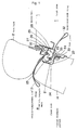
- Fig. 1 is a schematic view showing an apparatus for permitting pass-through between a vehicle compartment and a trunk room according to one embodiment of the present invention, which apparatus is installed on a rear seat of an automobile
- Fig. 2 is a cross-sectional view of a principal part of the apparatus of Fig. 1 when it is being operated from the side of the vehicle compartment
- Fig. 3 is a cross-sectional view of the principal part of the apparatus of Fig. 1 when it is operated from the side of the trunk room or cargo room of the vehicle.
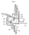
- Fig. 4 is a cross-sectional view showing the principal part of the apparatus of Fig. 1 when it is placed in the locked position for protecting the automobile against theft
- Fig. 5 is a perspective view showing the vehicle rear seat on which the apparatus of Fig. 1 is installed.
- the vehicle rear seat 11 principally consists of a seat back 12 and a seat cushion 13, and the seat back 12 includes a forward foldable portion 14 formed as a part thereof.
- the forward foldable portion 14 may be reclined forward or folded about a pivot provided at its lower part, to provide a flat cargo floor extension, so that the vehicle compartment R and the trunk room T communicate with each other through an opening that was occupied by the forward foldable portion 14.
- a lock device is provided at the upper part of the forward foldable portion 14, for holding the foldable portion 14 in its upright position.
- a generally V-shaped recess 21 is formed in the upper, rear face of the forward foldable portion 14 of the seat back 12, and a mounting bracket 22 is fixedly fitted in the recess 21.
- a first hook 24 is rotatably attached to the mounting bracket 22 by means of a support shaft 23.
- the first hook 24 is biased by a coil spring 25 as biasing means in the clockwise direction as seen in Fig. 1, and held by a stopper (not shown) in the position as shown in Fig. 1.
- a mounting bracket 26 is fixed to the upper rear face of the seat back 12, and a second hook 28 is rotatably attached to the mounting bracket 26 by means of a support shaft 27.
- the second hook 28 is biased by a coil spring 29 as biasing means in the clockwise direction as seen in Fig. 1, and held by a stopper 30 in the position as shown in Fig. 1.
- the first and second hooks 24, 28 engage with each other when the forward foldable portion 14 is held in the upright position, so as to engage the forward foldable portion 14 with the seat back 12 to thus keep the same in the upright position.
- a vehicle-compartment-side strap 31 as an operating member on the side of the vehicle compartment has a proximal end portion that is connected to the first hook 14, and a distal end portion that is exposed to the vehicle compartment R.
- the first hook 24 is rotated counterclockwise as viewed in Fig. 1 against the bias force of the coil spring 25, and disengaged from the second hook 28, so that the forward foldable portion 14 can be reclined forward or folded onto the seat cushion 13.
- a trunk-room-side strap 32 as an operating member on the side of the trunk room has a proximal end portion that is connected to the second hook 28, and a distal end portion that is exposed to the trunk room T.
- the second hook 28 When the strap 32 is pulled toward the trunk room T, the second hook 28 is rotated counterclockwise as viewed in Fig. 1 against the bias force of the coil spring 29, and disengaged from the first hook 24, so that the forward foldable portion 14 can be reclined forward or folded onto the seat cushion 13.
- a lock piece 33 is rotatably attached to the lower part of the mounting bracket 22, such that the lock piece 33 can be freely rotated by an operating member 34 that is exposed to the trunk room T.
- the distal end portion of the lock piece 33 protrudes upward through a through-hole 35 of the mounting bracket 22, so as to engage with the first hook 24 and inhibit rotation of the first hook 24.
- the operating member 34 may be operated to rotate the lock piece 33 so as to bring its distal end portion into engagement with the first hook 24, so that the first hook 24 is prevented from being rotated counterclockwise as seen in Fig. 1, and disengaged or released from the second hook 28 from the side of the vehicle compartment R.
- the forward foldable portion 14 when the forward foldable portion 14 is in the upright position as shown in Fig. 1, the first hook 24 and the second hook 28 are held in engagement with each other such that the forward foldable portion 14 is retained in the upright position for engagement with the seat back 12.
- the first hook 24 is rotated against the bias force of the coil spring 34 and disengaged or released from the second hook 28, as shown in Fig. 2, so that the forward foldable portion 14 leans forward and lies down on the seat cushion 13.
- the vehicle compartment R and the trunk room T communicate with each other through an opening previously occupied by the foldable portion 14, thus enabling one in the vehicle compartment to put cargo into or take it out of the trunk room T.
- the second hook 28 is rotated against the bias force of the coil spring 29 and disengaged or released from the first hook 24, as shown in Fig. 3, so that the forward foldable portion 14 is able to lean forward and lie down onto the seat cushion 13.
- the vehicle compartment R and the trunk room T communicate with each other through an opening previously occupied by the foldable portion 14, thus enabling one in the vehicle compartment to put cargo into or take it out of the trunk room T.
- the lock piece 33 prevents the first hook 24 from being rotated in such a direction as to release its engagement with the second hook 28. If the vehicle-compartment-side strap 31 is pulled toward the vehicle compartment R in this state of Fig. 4 with the forward foldable portion 14 being in the upright position, the first hook 24 will not rotate, and cannot be disengaged from the second hook 28. Thus, the forward foldable portion 14 is prevented from being reclined forward or folded, making it impossible to access the trunk room T from the vehicle compartment R for entry or removal of cargo.
- the operating member 34 for rotating the lock piece 33 is provided on the rear face of the forward foldable portion 14 of the seat back 12. With this arrangement, the operating member 34 may be operated to rotate the lock piece 33 to bring its distal portion into engagement with the first hook 24 while the forward foldable portion 14 is in the folded position, and then the forward foldable portion 14 may be raised to its upright position, so that the first hook 24 engages with the second hook 28 through rotation of the second hook 28, and the forward foldable portion 14 is held in the upright position. In this state, the forward foldable portion 14 is prevented from leaning forward even if the vehicle-compartment-side strap 31 is pulled toward the vehicle compartment R. This arrangement eliminates the need to go around to the side of he trunk room T to operate the operating member 34 for placing the apparatus in the locked position, as in the conventional apparatus.
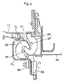
- slider 40 and a coil spring 42 are provided instead of two coil springs 25, 29.
- the slider 40 is slidably attached to the mounting bracket 22 so that the slider 40 can abut to the upper end of the second hook 28 when the foldable portion 14 is held in the upright position.
- One end of the coil spring 42 is connected to the first hook 24 and the other end is connected to the slider 40 so that the spring 42 biases the first hook 24 in the clockwise direction and the second hook 28 via the slider 40 in the clock wise direction in Fig. 6 when the forward foldable portion 14 is held in the upright position.
- the first and second hook 24, 28 engage with each other when the foldable portion 14 is held in the upright position.
- a coil spring 44 is provided instead of two coil springs 25, 29.
- One end of the coil spring 44 is connected to the second hook 28 and the other end can abut the lower end of the first hook 24 so that the coil spring 44 biases the first and second hook 24, 28 in the clockwise direction, respectively when the forward foldable portion 14 is held in the upright position.
- the first and second hook 24, 28 engage with each other when the foldable portion 14 is held in the upright position.
- the coil spring 44 is arranged at the seat back 12 side, it is possible to arrange the coil spring 44 at the forward fordable portion 14.
- one end of the coil spring is connected to the first hook 24 and the other end can abut the upper end of the second hook 28 so that the coil spring biases the first hook and second hook 24, 28, respectively when the forward foldable portion 14 is held in the upright position.
- compartment-side strap 31 and the trunk-room-side strap 32 provided as the operating members on the side of the vehicle compartment and the trunk room, respectively, may be replaced by operating levers that are coupled to the first hook 24 and the second hook 28, respectively.
- the vehicle-compartment-side strap 31 is connected to the first hook 24, and the trunk-room-side strap 32 is connected to the second hook 28. It is, however, possible to connect the vehicle-compartment-side strap 31 to the second hook 28, and connect the trunk-room-side strap 32 to the first hook 24.
- the closure member is provided by the forward foldable portion 14 as a part of the seat back 12 in the illustrated embodiment
- the present invention may be applied to a rear seat structure in which the seat back 12 as a whole can be reclined forward to a folded cargo configuration, and is thus regarded as the closure member.
Landscapes
- Engineering & Computer Science (AREA)
- Mechanical Engineering (AREA)
- Aviation & Aerospace Engineering (AREA)
- Transportation (AREA)
- Seats For Vehicles (AREA)
Applications Claiming Priority (2)
| Application Number | Priority Date | Filing Date | Title |
|---|---|---|---|
| JP16476498A JP3487179B2 (ja) | 1998-06-12 | 1998-06-12 | トランクスルー装置 |
| JP16476498 | 1998-06-12 |
Publications (2)
| Publication Number | Publication Date |
|---|---|
| EP0965488A1 true EP0965488A1 (de) | 1999-12-22 |
| EP0965488B1 EP0965488B1 (de) | 2002-09-11 |
Family
ID=15799492
Family Applications (1)
| Application Number | Title | Priority Date | Filing Date |
|---|---|---|---|
| EP99111376A Expired - Lifetime EP0965488B1 (de) | 1998-06-12 | 1999-06-10 | Vorrichtung zur Ermöglichung des Durchlasses zwischen Sitz- u. Kofferraum eines Kraftfahrzeuges |
Country Status (5)
| Country | Link |
|---|---|
| US (1) | US6302484B1 (de) |
| EP (1) | EP0965488B1 (de) |
| JP (1) | JP3487179B2 (de) |
| KR (1) | KR100300807B1 (de) |
| DE (1) | DE69902849T2 (de) |
Cited By (4)
| Publication number | Priority date | Publication date | Assignee | Title |
|---|---|---|---|---|
| DE102004028846B3 (de) * | 2004-06-16 | 2006-08-17 | Johnson Controls Gmbh | Fahrzeugkomponente und Verfahren zur Sicherung einer Klappe gegen Öffnen im Crashfall |
| WO2008113594A2 (de) | 2007-03-21 | 2008-09-25 | Johnson Controls Gmbh | Durchladeklappe für einen fahrzeugsitz |
| EP2098406A2 (de) * | 2008-02-28 | 2009-09-09 | Toyota Boshoku Corporation | Fahrzeugsitz |
| EP2196355A1 (de) * | 2008-12-12 | 2010-06-16 | Wagon Automotive | Einrastvorrichtung zum Fixieren eines Teils der Rückenlehne eines Autositzes auf einem Strukturteil des Fahrzeugs, und entsprechendes Fahrzeug |
Families Citing this family (11)
| Publication number | Priority date | Publication date | Assignee | Title |
|---|---|---|---|---|
| JP3571681B2 (ja) * | 2001-10-17 | 2004-09-29 | 紀行 音 | 収納式シート |
| US20030085605A1 (en) * | 2001-11-07 | 2003-05-08 | Hentges William J. | Seat and headrest system |
| US20040195888A1 (en) * | 2003-04-03 | 2004-10-07 | Johnson Controls Technology Company | Configurable vehicle seat |
| DE102004045988B3 (de) * | 2004-09-22 | 2005-12-01 | Faurecia Autositze Gmbh & Co. Kg | Anzeige zur Signalisierung der Nichtverriegelung einer klappbaren Rückenlehne eines Kraftfahrzeugsitzes |
| JP5121309B2 (ja) * | 2007-05-30 | 2013-01-16 | 富士重工業株式会社 | リヤシート装置および車輌 |
| JP5134288B2 (ja) * | 2007-05-28 | 2013-01-30 | 富士重工業株式会社 | リヤシート装置および車両 |
| US8047614B2 (en) | 2007-05-28 | 2011-11-01 | Nhk Spring Co., Ltd. | Seat apparatus and vehicle |
| US7490908B2 (en) * | 2007-07-03 | 2009-02-17 | Lear Corporation | Integrated latch assembly |
| DE112008004275B3 (de) * | 2008-10-28 | 2018-10-18 | Lear Corp. | Sitzverriegelung und Haltesystem |
| US8267458B2 (en) * | 2010-03-25 | 2012-09-18 | Honda Motor Co., Ltd. | Seat assembly for a vehicle having a vertically extended striker mechanism |
| US11731546B1 (en) * | 2020-07-13 | 2023-08-22 | Waymo Llc | Seat back release blocker |
Citations (4)
| Publication number | Priority date | Publication date | Assignee | Title |
|---|---|---|---|---|
| DE3322511A1 (de) * | 1983-06-23 | 1985-01-10 | Adam Opel AG, 6090 Rüsselsheim | Mittelarmlehne fuer kraftfahrzeugsitze |
| EP0154927A2 (de) * | 1984-03-12 | 1985-09-18 | Bayerische Motoren Werke Aktiengesellschaft, Patentabteilung AJ-3 | Transportvorrichtung, insbesondere für Skier, in einem Personenkraftwagen |
| DE4305248A1 (de) * | 1993-02-20 | 1994-08-25 | Bayerische Motoren Werke Ag | Verstelleinrichtung an einer Klappe |
| FR2743589A1 (fr) * | 1996-01-11 | 1997-07-18 | Faure Bertrand Equipements Sa | Dispositif de verrouillage d'une trappe d'un dossier de siege arriere d'un vehicule automobile |
Family Cites Families (11)
| Publication number | Priority date | Publication date | Assignee | Title |
|---|---|---|---|---|
| JPS6437740U (de) | 1987-08-31 | 1989-03-07 | ||
| JPH01102033U (de) | 1987-12-28 | 1989-07-10 | ||
| JP2737261B2 (ja) * | 1989-06-30 | 1998-04-08 | 旭硝子株式会社 | フッ素化炭化水素系組成物 |
| JPH02143222U (de) * | 1989-04-28 | 1990-12-05 | ||
| JP2861058B2 (ja) * | 1989-06-08 | 1999-02-24 | ブラザー工業株式会社 | 可変リラクタンスモータの励磁制御装置 |
| US5106158A (en) * | 1991-08-22 | 1992-04-21 | Chrysler Corporation | Integral child seat module adjustable head support latch |
| US5540479A (en) * | 1992-05-22 | 1996-07-30 | Thomas; Alan V. | Vehicle seats |
| US5366270A (en) * | 1992-10-13 | 1994-11-22 | Lear Seating Corporation | Child resistant seat including foam and flex layer combination |
| JP2666716B2 (ja) * | 1993-12-27 | 1997-10-22 | 池田物産株式会社 | 組込み式チャイルドシート |
| KR0173628B1 (ko) * | 1995-12-22 | 1999-02-18 | 김태구 | 시트 개폐차량의 트렁크 전면 차단구조 |
| US5700054A (en) * | 1996-04-23 | 1997-12-23 | Lear Corporation | Vehicle seat assembly including integral child restraint seat |
-
1998
- 1998-06-12 JP JP16476498A patent/JP3487179B2/ja not_active Expired - Fee Related
-
1999
- 1999-06-10 EP EP99111376A patent/EP0965488B1/de not_active Expired - Lifetime
- 1999-06-10 DE DE69902849T patent/DE69902849T2/de not_active Expired - Lifetime
- 1999-06-11 KR KR1019990021691A patent/KR100300807B1/ko not_active IP Right Cessation
- 1999-06-14 US US09/332,608 patent/US6302484B1/en not_active Expired - Lifetime
Patent Citations (4)
| Publication number | Priority date | Publication date | Assignee | Title |
|---|---|---|---|---|
| DE3322511A1 (de) * | 1983-06-23 | 1985-01-10 | Adam Opel AG, 6090 Rüsselsheim | Mittelarmlehne fuer kraftfahrzeugsitze |
| EP0154927A2 (de) * | 1984-03-12 | 1985-09-18 | Bayerische Motoren Werke Aktiengesellschaft, Patentabteilung AJ-3 | Transportvorrichtung, insbesondere für Skier, in einem Personenkraftwagen |
| DE4305248A1 (de) * | 1993-02-20 | 1994-08-25 | Bayerische Motoren Werke Ag | Verstelleinrichtung an einer Klappe |
| FR2743589A1 (fr) * | 1996-01-11 | 1997-07-18 | Faure Bertrand Equipements Sa | Dispositif de verrouillage d'une trappe d'un dossier de siege arriere d'un vehicule automobile |
Cited By (11)
| Publication number | Priority date | Publication date | Assignee | Title |
|---|---|---|---|---|
| DE102004028846B3 (de) * | 2004-06-16 | 2006-08-17 | Johnson Controls Gmbh | Fahrzeugkomponente und Verfahren zur Sicherung einer Klappe gegen Öffnen im Crashfall |
| US8864184B2 (en) | 2004-06-16 | 2014-10-21 | Johnson Controls Gmbh | Backrest lid |
| WO2008113594A2 (de) | 2007-03-21 | 2008-09-25 | Johnson Controls Gmbh | Durchladeklappe für einen fahrzeugsitz |
| DE102007060319A1 (de) | 2007-03-21 | 2008-09-25 | Johnson Controls Gmbh | Durchladeklappe für einen Fahrzeugsitz |
| WO2008113594A3 (de) * | 2007-03-21 | 2008-11-27 | Johnson Controls Gmbh | Durchladeklappe für einen fahrzeugsitz |
| US8177298B2 (en) | 2007-03-21 | 2012-05-15 | Johnson Controls Gmbh | Loading flap for a vehicle seat |
| DE102007060319B4 (de) * | 2007-03-21 | 2016-04-28 | Johnson Controls Gmbh | Durchladeklappe für einen Fahrzeugsitz |
| EP2098406A2 (de) * | 2008-02-28 | 2009-09-09 | Toyota Boshoku Corporation | Fahrzeugsitz |
| EP2098406A3 (de) * | 2008-02-28 | 2010-02-17 | Toyota Boshoku Corporation | Fahrzeugsitz |
| EP2196355A1 (de) * | 2008-12-12 | 2010-06-16 | Wagon Automotive | Einrastvorrichtung zum Fixieren eines Teils der Rückenlehne eines Autositzes auf einem Strukturteil des Fahrzeugs, und entsprechendes Fahrzeug |
| FR2939729A1 (fr) * | 2008-12-12 | 2010-06-18 | Wagon Automotive | Dispositif de verrouillage d'une partie de dossier d'un siege de vehicule automobile sur une partie structurelle du vehicule, et vehicule correspondant. |
Also Published As
| Publication number | Publication date |
|---|---|
| JPH11348626A (ja) | 1999-12-21 |
| EP0965488B1 (de) | 2002-09-11 |
| US6302484B1 (en) | 2001-10-16 |
| DE69902849D1 (de) | 2002-10-17 |
| KR100300807B1 (ko) | 2001-09-22 |
| JP3487179B2 (ja) | 2004-01-13 |
| DE69902849T2 (de) | 2003-08-07 |
| KR20000006099A (ko) | 2000-01-25 |
Similar Documents
| Publication | Publication Date | Title |
|---|---|---|
| US6302484B1 (en) | Apparatus for permitting pass-through between vehicle compartment and trunk room | |
| JP4296643B2 (ja) | シートバックロック装置 | |
| EP1341683B1 (de) | Auf den boden faltbarer sitz mit einem freitragenden sitzteil | |
| JPS59149833A (ja) | 車輛用のリヤシ−トにおけるロツク装置 | |
| JPH0628351Y2 (ja) | 自動車用リアシ−ト | |
| JPS5821781Y2 (ja) | 自動車のリヤバックレスト前倒操作機構 | |
| JPS6326974Y2 (de) | ||
| JPH0228979Y2 (de) | ||
| JP3628904B2 (ja) | 自動車用シートの収納姿勢保持装置 | |
| JP3916434B2 (ja) | 固定装置の係止具 | |
| JP3815004B2 (ja) | 車両用シートの脱着機構 | |
| JPH0428843Y2 (de) | ||
| JPH0233528B2 (ja) | Jidoshanoshiitosochi | |
| JP2008221907A (ja) | 車両用シート装置 | |
| JPH09249073A (ja) | 車両のラゲージスペース規定構造 | |
| JPH0319472Y2 (de) | ||
| JPH0522437Y2 (de) | ||
| JP3517136B2 (ja) | 自動車用シートの支持装置 | |
| JP4058282B2 (ja) | 車両用折り畳みシート | |
| JPH0741642Y2 (ja) | シートベルト付きシート | |
| JPH059949Y2 (de) | ||
| JPH0737999Y2 (ja) | 車両用リヤーシートのアームレスト構造 | |
| JPH0233577Y2 (de) | ||
| JPH072008A (ja) | 自動車用シートのロック装置 | |
| JP2000001155A (ja) | シートベルト装置 |
Legal Events
| Date | Code | Title | Description |
|---|---|---|---|
| PUAI | Public reference made under article 153(3) epc to a published international application that has entered the european phase |
Free format text: ORIGINAL CODE: 0009012 |
|
| 17P | Request for examination filed |
Effective date: 19990706 |
|
| AK | Designated contracting states |
Kind code of ref document: A1 Designated state(s): DE FR NL |
|
| AX | Request for extension of the european patent |
Free format text: AL;LT;LV;MK;RO;SI |
|
| AKX | Designation fees paid |
Free format text: DE FR NL |
|
| 17Q | First examination report despatched |
Effective date: 20010301 |
|
| GRAG | Despatch of communication of intention to grant |
Free format text: ORIGINAL CODE: EPIDOS AGRA |
|
| GRAG | Despatch of communication of intention to grant |
Free format text: ORIGINAL CODE: EPIDOS AGRA |
|
| GRAH | Despatch of communication of intention to grant a patent |
Free format text: ORIGINAL CODE: EPIDOS IGRA |
|
| GRAH | Despatch of communication of intention to grant a patent |
Free format text: ORIGINAL CODE: EPIDOS IGRA |
|
| GRAH | Despatch of communication of intention to grant a patent |
Free format text: ORIGINAL CODE: EPIDOS IGRA |
|
| GRAH | Despatch of communication of intention to grant a patent |
Free format text: ORIGINAL CODE: EPIDOS IGRA |
|
| GRAA | (expected) grant |
Free format text: ORIGINAL CODE: 0009210 |
|
| AK | Designated contracting states |
Kind code of ref document: B1 Designated state(s): DE FR NL |
|
| REF | Corresponds to: |
Ref document number: 69902849 Country of ref document: DE Date of ref document: 20021017 |
|
| ET | Fr: translation filed | ||
| PLBE | No opposition filed within time limit |
Free format text: ORIGINAL CODE: 0009261 |
|
| STAA | Information on the status of an ep patent application or granted ep patent |
Free format text: STATUS: NO OPPOSITION FILED WITHIN TIME LIMIT |
|
| 26N | No opposition filed |
Effective date: 20030612 |
|
| REG | Reference to a national code |
Ref country code: FR Ref legal event code: CA |
|
| REG | Reference to a national code |
Ref country code: FR Ref legal event code: PLFP Year of fee payment: 18 |
|
| REG | Reference to a national code |
Ref country code: FR Ref legal event code: PLFP Year of fee payment: 19 |
|
| REG | Reference to a national code |
Ref country code: FR Ref legal event code: PLFP Year of fee payment: 20 |
|
| PGFP | Annual fee paid to national office [announced via postgrant information from national office to epo] |
Ref country code: DE Payment date: 20180530 Year of fee payment: 20 |
|
| PGFP | Annual fee paid to national office [announced via postgrant information from national office to epo] |
Ref country code: FR Payment date: 20180511 Year of fee payment: 20 Ref country code: NL Payment date: 20180514 Year of fee payment: 20 |
|
| REG | Reference to a national code |
Ref country code: DE Ref legal event code: R071 Ref document number: 69902849 Country of ref document: DE |
|
| REG | Reference to a national code |
Ref country code: NL Ref legal event code: MK Effective date: 20190609 |