EP0964110A2 - Dämmelement zur Wärme- und/oder Schalldämmung einer Gebäudedachkonstruktion - Google Patents
Dämmelement zur Wärme- und/oder Schalldämmung einer Gebäudedachkonstruktion Download PDFInfo
- Publication number
- EP0964110A2 EP0964110A2 EP99110201A EP99110201A EP0964110A2 EP 0964110 A2 EP0964110 A2 EP 0964110A2 EP 99110201 A EP99110201 A EP 99110201A EP 99110201 A EP99110201 A EP 99110201A EP 0964110 A2 EP0964110 A2 EP 0964110A2
- Authority
- EP
- European Patent Office
- Prior art keywords
- plate
- insulating element
- element according
- rafters
- insulation
- Prior art date
- Legal status (The legal status is an assumption and is not a legal conclusion. Google has not performed a legal analysis and makes no representation as to the accuracy of the status listed.)
- Withdrawn
Links
Images

Classifications
-
- E—FIXED CONSTRUCTIONS
- E04—BUILDING
- E04D—ROOF COVERINGS; SKY-LIGHTS; GUTTERS; ROOF-WORKING TOOLS
- E04D13/00—Special arrangements or devices in connection with roof coverings; Protection against birds; Roof drainage ; Sky-lights
- E04D13/16—Insulating devices or arrangements in so far as the roof covering is concerned, e.g. characterised by the material or composition of the roof insulating material or its integration in the roof structure
- E04D13/1606—Insulation of the roof covering characterised by its integration in the roof structure
- E04D13/1612—Insulation of the roof covering characterised by its integration in the roof structure the roof structure comprising a supporting framework of roof purlins or rafters
- E04D13/1625—Insulation of the roof covering characterised by its integration in the roof structure the roof structure comprising a supporting framework of roof purlins or rafters with means for supporting the insulating material between the purlins or rafters
-
- E—FIXED CONSTRUCTIONS
- E04—BUILDING
- E04B—GENERAL BUILDING CONSTRUCTIONS; WALLS, e.g. PARTITIONS; ROOFS; FLOORS; CEILINGS; INSULATION OR OTHER PROTECTION OF BUILDINGS
- E04B1/00—Constructions in general; Structures which are not restricted either to walls, e.g. partitions, or floors or ceilings or roofs
- E04B1/62—Insulation or other protection; Elements or use of specified material therefor
- E04B1/74—Heat, sound or noise insulation, absorption, or reflection; Other building methods affording favourable thermal or acoustical conditions, e.g. accumulating of heat within walls
- E04B1/76—Heat, sound or noise insulation, absorption, or reflection; Other building methods affording favourable thermal or acoustical conditions, e.g. accumulating of heat within walls specifically with respect to heat only
- E04B1/7654—Heat, sound or noise insulation, absorption, or reflection; Other building methods affording favourable thermal or acoustical conditions, e.g. accumulating of heat within walls specifically with respect to heat only comprising an insulating layer, disposed between two longitudinal supporting elements, e.g. to insulate ceilings
- E04B1/7658—Heat, sound or noise insulation, absorption, or reflection; Other building methods affording favourable thermal or acoustical conditions, e.g. accumulating of heat within walls specifically with respect to heat only comprising an insulating layer, disposed between two longitudinal supporting elements, e.g. to insulate ceilings comprising fiber insulation, e.g. as panels or loose filled fibres
-
- E—FIXED CONSTRUCTIONS
- E04—BUILDING
- E04B—GENERAL BUILDING CONSTRUCTIONS; WALLS, e.g. PARTITIONS; ROOFS; FLOORS; CEILINGS; INSULATION OR OTHER PROTECTION OF BUILDINGS
- E04B1/00—Constructions in general; Structures which are not restricted either to walls, e.g. partitions, or floors or ceilings or roofs
- E04B1/62—Insulation or other protection; Elements or use of specified material therefor
- E04B1/74—Heat, sound or noise insulation, absorption, or reflection; Other building methods affording favourable thermal or acoustical conditions, e.g. accumulating of heat within walls
- E04B1/76—Heat, sound or noise insulation, absorption, or reflection; Other building methods affording favourable thermal or acoustical conditions, e.g. accumulating of heat within walls specifically with respect to heat only
- E04B2001/7683—Fibrous blankets or panels characterised by the orientation of the fibres
-
- E—FIXED CONSTRUCTIONS
- E04—BUILDING
- E04B—GENERAL BUILDING CONSTRUCTIONS; WALLS, e.g. PARTITIONS; ROOFS; FLOORS; CEILINGS; INSULATION OR OTHER PROTECTION OF BUILDINGS
- E04B1/00—Constructions in general; Structures which are not restricted either to walls, e.g. partitions, or floors or ceilings or roofs
- E04B1/62—Insulation or other protection; Elements or use of specified material therefor
- E04B1/74—Heat, sound or noise insulation, absorption, or reflection; Other building methods affording favourable thermal or acoustical conditions, e.g. accumulating of heat within walls
- E04B1/76—Heat, sound or noise insulation, absorption, or reflection; Other building methods affording favourable thermal or acoustical conditions, e.g. accumulating of heat within walls specifically with respect to heat only
- E04B2001/7695—Panels with adjustable width
Definitions
- the invention relates to an insulation element for thermal and / or acoustic insulation a building roof construction, in particular a rafters and purlin roof a residential building that can be installed between neighboring rafters.
- Insulating elements for heat and / or sound insulation are in itself by the load-bearing parts and through outside covers / seals respectively the room-side cladding of the roof structures resulting spaces built-in.
- the load-bearing parts mostly consist of solid wood, glued wood, Bridge beams, boards, etc.
- Another application of such insulation elements exists in the area of floor ceilings as a boundary surface to the surroundings, as far as these floor ceilings at least with supporting wood clad on the underside are provided, between which insulation elements can be arranged.
- the insulation elements to be preferred are made of mineral wool fibers made of insulating felts glued onto carrier foils in graded widths between 50 and 100 cm, so that an insulating felt is selected according to the rafter width and can be processed.
- the graded widths lead both from the Manufacturer as well as on the part of the stocking dealer or the processing Companies to a large stock of individual products.
- the construction area to be insulated, especially with regard to the rafter width carefully measured before the insulation felts of the appropriate width are selected, whereby in usually the gradation is in the 10 cm range, so that additional cutting work insulation felts are required.
- the width of the insulation felt is greater than the rafter width large, it is necessary to cut the insulation felt through a longitudinal cut to the rafter width adapt.
- the insulation felt may be adjusted over several meters, which is cumbersome in the mostly narrow loft spaces. It there is also a risk that the generally in the rolled state supplied insulation felt can only be processed imprecisely, so that only one insufficient heat and / or sound insulation is achieved. Insulation felts therefore mostly pressed into the rafters with excess width, which leads to building physics Problems due to lack of back ventilation can, at least always results in increased consumption of insulation materials.
- the poor Laying - also with sub-widths - is covered by the carrier foils on the underside and is usually not recognizable to the building owner.
- Another solution is to use insulation felts with a higher bending stiffness to use that rolled up under pressure in the manufacturing plant to save space be and of which after unrolling sections according to the width of the Rafter fields are separated. Applied to one of the large surfaces striped markings make it easier to cut to length. But it is considered a disadvantage considered that with increasing insulation thicknesses, for example ⁇ 140 mm different tensile and compressive stresses in the zones of the insulation roll become too large so that they tear on the outside or on the inside structural damage from over-compression. Reduce both damages the stiffness of the insulating felt section, so that there is a not inconsiderable risk, that the insulation element under the force of gravity from the rafter field falls out before a load-bearing sub-layer is installed.
- Rollable and compressible insulation felts usually have a pronounced laminar arrangement of the individual fibers.
- One results from this orientation high compressibility perpendicular to the large areas and on the other hand one extremely low transverse tensile strength and shear strength.
- When rolling up Such insulation materials are shifted against each other. After unrolling, the individual layers gap apart, which naturally increases a reduction in strength and difficulties when installing these insulation felts can lead.
- the length of the rolled-up insulation felt or the roll diameter drastically increase. In any case, there are disadvantages with regard to Processing the insulation felts.
- the invention has for its object to further develop a generic insulation element such that its installation between rafters is significantly simplified and rationalized without the disadvantages described above, in particular a deterioration in thermal and acoustic insulation is caused.
- the insulating element consists of a plate made of mineral wool fibers, the mineral wool fibers being aligned at least ⁇ 90 degrees to the adjacent side surfaces of the rafters in the area of the side surfaces of the plate adjacent to the rafters, and wherein the plate is a Has a length of at least 2 m with a material thickness of ⁇ 100 mm and usual width.
- the insulation element according to the invention for thermal and / or acoustic insulation Building roof construction thus shows sufficient stability to to be placed between the rafters without the risk of falling out consists.
- the fiber arrangement also enables an extraordinary good interlocking of the insulation material with the rafters surface, because of the fiber arrangement on the one hand the necessary rigidity for the required friction pressure provides and on the other hand sufficient compressibility of the Insulation board in its longitudinal direction allows.
- Insulating element advantageous that a large-sized plate is formed can be cut according to the rafter spacing without that sections can no longer be used.
- the design of the Insulation element as a large-format plate thus enables a far-reaching Adaptation of the insulation element to the rafter spacing and beyond that economical and fast processing of the insulation elements.
- the angle between the adjacent side surfaces of the rafters and the grain between 0 and 45 degrees. It is advantageous here that the positive engagement of the The flatter the fibers, the tighter the insulation material with the rafters surface are. On the other hand, the stiffness decreases parallel to the big ones Surfaces so that the clamping effect of the insulation elements drops.
- the optimal one Angle of attack is dependent on the width of the rafter field, however also significantly from the desired resistance moment of the insulation material, which is significantly influenced by the thickness of the insulation material.
- the arrangement of the Individual fibers are therefore dependent on a further feature of the invention varies from the thickness of the insulation.
- the plate preferably has a material thickness of more than 120 mm also to meet the higher requirements for insulation performance.
- the plate Glass and / or rock wool fibers and / or their derivatives are provided.
- the mineral wool fibers are preferably over the entire extent of the Plate at an angle ⁇ 90 degrees, preferably ⁇ 45 degrees to the adjacent Side surfaces of the rafters aligned, so that the advantageous orientation of the Mineral wool fibers are also present in the areas after cutting to length the plate are outer surfaces which abut the rafters.
- the individual fibers are completely oblique to the in the direction of the longitudinal axis large surfaces.
- a surcharge of, for example, 1.2 cm from the Insulation board separated, which sections are pressed between the rafters.
- the usual installation technique is that the section first to a the rafters flanks are attached and then pushed into the rafters field.
- the inventive arrangement of the individual fibers allows the insulation element be compressed more with the same effort, so that it is easier in the rafter field can be pushed in.
- the individual fibers in the edge area are due to the possible large compression of the insulation element when installed in redirected and displaced only slightly in a deeper area, whereby there are advantages in the insulation effect of the insulation elements.
- the plate in at least one large Surface has incisions that are perpendicular to the length of the tarpaulin run.
- the incisions are evenly spaced from one another, for example, individual cuts compared to other cuts through greater or smaller depth and / or width as well as color markings or the like are highlighted.
- the one in the big surfaces Incisions made at the factory can have depths of at least 5 mm have several centimeters.
- the section of the incised The plate is clamped between the rafters so that the cuts on the top, i.e. installed in the pressure zone of the horizontal or parallel to the roof pitch Insulation element.
- the incisions can be made at regular intervals, for example be provided every 2 cm.
- the regularly required width of the insulation from 1 to 5 cm, preferably taken into account 1 to 2 cm. If, for example, regionally determined Rafter widths are preferred, they can be alone or excellent be marked.
- a surface the plate is partially or completely provided with a color coating to a To ensure orientation for the installation of the plate.
- the insulation panel on one side with, for example, glass fleece, tissue, paper or similar. to cover non-positively.
- the insulation element is expediently installed so that the lamination in the Train zone, i.e. is arranged on the room side.
- the insulation element next to the insulation board Has insulation board and / or insulation felt section, which is arranged laterally on the board , the width of which corresponds to the thickness of the plate.
- the insulation board and / or insulation felt section is glued to a glass fleece.
- a mineral wool product is used for this, which is a lower one Compressive strength, as the mineral wool product for the insulation board.
- the insulation material for the insulation board and / or insulation felt section a compressive strength that is parallel between that of the insulation board to the large areas and a slightly compressible insulation felt.
- the sections are used as filler pieces, so that after processing a Plate narrow sections must be separated from the next plate.
- the fibers preferably run in the insulation board and / or insulation felt section essentially parallel to the adjacent side surfaces of the rafters.
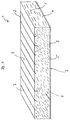
- Figure 1 is an insulation element 1 for thermal and / or acoustic insulation Building roof construction, in particular a rafter and purlin roof Residential building shown.
- the insulation element 1 consists of a plate 2 with two large surfaces 3, two narrow sides 4 and two long sides 5.
- the Narrow sides 4 and the long sides 5 are in relation to one another and to the large surfaces 3 each arranged at right angles.
- the insulation element 1 consists of a variety of mineral wool fibers 6, the are arranged at an angle to the large surfaces 3, which is approximately 45 Degrees and can be between 0 and 45 degrees. Every long side 5 of the plate 2 is 2 m or 2.4 m long. The material thickness of the plate 1 is 100 mm, the plate 2 having a usual width.
- the mineral wool fibers 6 are made from a melting and defibration process Natural or artificial stones made so that it is rock wool fibers acts.
- the plate 2 incisions 7 running at right angles to their longitudinal extent, one Have a depth of at least 5 mm.
- the incisions 7 are at regular intervals arranged to each other, with some incisions 7 a greater depth than have adjacent cuts 7.
- the plate 2 has a lamination 8, the entire surface is arranged on the large surface 3.
- the liner 8 is a glass fleece trained and arranged with installed plate 2 in the pull zone when the Plate 2 as intended, i.e. with lamination in the interior 8 is installed.
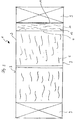
- FIG. 2 shows the arrangement of an insulating element 1 between two neighboring ones Rafters 9 shown a roof structure. It can be seen that the Plate 2 extends between the rafters 9, the two narrow sides 4 form and supported non-positively on the adjacent side surfaces 10 of the rafters 9 are. Due to the course of the mineral wool fibers 6 within the plate 2 Plate 2 in the direction of its longitudinal extent sufficiently compressible to an excess between the rafters 9 can be installed, the Elasticity of the tarpaulin 2 a sufficient contact pressure between the side surfaces 10 and the narrow sides 4 of the plate 2 provides. Beyond that achieved a high bending stiffness through the course of the mineral wool fibers 6 sufficient, the plate 2 in its position shown in Figures 2 and 3 between to hold the rafters 9.
- FIG. 3 Another embodiment of an insulation element 1 is shown in FIG. 3.
- the plate 2 is on a narrow side 4 Insulating felt section 11 arranged on the one hand on the narrow side 4 of the Plate 2 and on the other hand on the rafters 9, the fibers 12 in the Insulating felt section 11 essentially parallel to the adjacent side surface 10 of rafters 9 run.
- the insulation felt section 11 can here with the plate 2 be connected, in particular a glued-on glass fleece for a connection between the plate 2 and the insulating felt section 11 is suitable.
Landscapes
- Engineering & Computer Science (AREA)
- Architecture (AREA)
- Civil Engineering (AREA)
- Structural Engineering (AREA)
- Physics & Mathematics (AREA)
- Acoustics & Sound (AREA)
- Electromagnetism (AREA)
- Building Environments (AREA)
Abstract
Description
- Figur 1
- eine perspektivische Darstellung eines Dämmelementes in einer ersten Ausführungsform;
- Figur 2
- ein Dämmelement in einer zweiten Ausführungsform in Einbaulage zwischen zwei Sparren und
- Figur 3
- ein Dämmelement in einer drillen Ausführungsform in Einbaulage zwischen zwei Sparren.
Claims (16)
- Dämmelement zur Wärme- und/oder Schalldämmung einer Gebäudedachkonstruktion, insbesondere eines Sparren- und Pfettendachs eines Wohngebäudes, welches zwischen benachbarten Sparren (9) einbaubar ist, bestehend aus einer Platte (2) aus Mineralwollefasern (6), wobei die Mineratwollefasern (6) zumindest im Bereich der an den Sparren (9) anliegenden Seitenflächen (4) der Platte (2) unter einem Winkel < 90 Grad zu den anliegenden Seitenflächen (10) der Sparren (9) ausgerichtet sind und wobei die Platte (2) eine Länge von zumindest 2 m bei einer Materialstärke von ≥ 100 mm und üblicher Breite aufweist.
- Dämmelement nach Anspruch 1,
dadurch gekennzeichnet,daß der Winkel zwischen den anliegenden Seitenflächen (10) der Sparren (9) und dem Faserverlauf zwischen 0 und 45 Grad beträgt. - Dämmelement nach Anspruch 1,
dadurch gekennzeichnet,daß die Platte eine Materialstärke von ≥ 120 mm aufweist. - Dämmelement nach Anspruch 1,
dadurch gekennzeichnet,daß die Platte (2) aus Glas- und/oder Steinwollefasern und/oder deren Derivaten besteht. - Dämmelement nach Anspruch 1,
dadurch gekennzeichnet,daß die Mineralwollefasern (6) über die gesamte Erstreckung der Platte (2) unter dem Winkel < 90 Grad, vorzugsweise zwischen 0 und 45 Grad zu den anliegenden Seitenflächen der Sparren (9) ausgerichtet sind. - Dämmelement nach Anspruch 5,
dadurch gekennzeichnet,daß die Platte (2) in zumindest einer großen Oberfläche Einschnitte (7) aufweist, die rechtwinklig zur Längserstreckung der Platte (2) verlaufen. - Dämmelement nach Anspruch 6,
dadurch gekennzeichnet,daß die Einschnitte (7) in gleichmäßigen Abständen zueinander angeordnet sind. - Dämmelement nach Anspruch 6,
dadurch gekennzeichnet, daß einzelne Einschnitte (7) gegenüber anderen Einschnitte (7) durch Tiefe, Breite, Farbmarkierungen oder dergleichen markiert sind. - Dämmelement nach Anspruch 1,
dadurch gekennzeichnet,daß die Platte (2) einseitig eine Kaschierung (8) aufweist. - Dämmelement nach Anspruch 9,
dadurch gekennzeichnet,daß die Kaschierung (8) als Glasvlies, -gewebe, Papier oder dergleichen ausgebildet ist. - Dämmelement nach Anspruch 9,
dadurch gekennzeichnet,daß die Kaschierung (8) auf der der Oberfläche (3) mit den Einschnitten (7) gegenüberliegenden Oberfläche (3) der Platte (2) angeordnet ist. - Dämmelement nach Anspruch 1,
dadurch gekennzeichnet,daß eine Oberfläche (3) der Platte (2) partiell oder vollständig mit einem Farbüberzug versehen ist. - Dämmelement nach Anspruch 9,
dadurch gekennzeichnet,daß die Kaschierung (8) in der Zugzone der eingebauten Platte (2) angeordnet ist. - Dämmelement nach Anspruch 1,
dadurch gekennzeichnet,daß an der Platte (2) seitlich ein Dämmplatten- und/oder Dämmfilzabschnitt (11) angeordnet ist, dessen Breite mit der Dicke der Platte (2) übereinstimmt. - Dämmelement nach Anspruch 14,
dadurch gekennzeichnet,daß der Dämmplatten- und/oder Dämmfilzabschnitt (11) auf einem Glasvlies aufgeklebt ist. - Dämmelement nach Anspruch 14,
dadurch gekennzeichnet,daß die Fasern (12) im Dämmplatten- und/oder Dämmfilzabschnitt (11) im wesentlichen parallel zu den anliegenden Seitenflächen (10) der Sparren (9) verlaufen
Applications Claiming Priority (2)
| Application Number | Priority Date | Filing Date | Title |
|---|---|---|---|
| DE19826137 | 1998-06-12 | ||
| DE1998126137 DE19826137A1 (de) | 1998-06-12 | 1998-06-12 | Dämmelement zur Wärme- und/oder Schalldämmung einer Gebäudedachkonstruktion |
Publications (2)
| Publication Number | Publication Date |
|---|---|
| EP0964110A2 true EP0964110A2 (de) | 1999-12-15 |
| EP0964110A3 EP0964110A3 (de) | 2000-12-27 |
Family
ID=7870651
Family Applications (1)
| Application Number | Title | Priority Date | Filing Date |
|---|---|---|---|
| EP99110201A Withdrawn EP0964110A3 (de) | 1998-06-12 | 1999-05-26 | Dämmelement zur Wärme- und/oder Schalldämmung einer Gebäudedachkonstruktion |
Country Status (2)
| Country | Link |
|---|---|
| EP (1) | EP0964110A3 (de) |
| DE (1) | DE19826137A1 (de) |
Cited By (6)
| Publication number | Priority date | Publication date | Assignee | Title |
|---|---|---|---|---|
| EP1333128A1 (de) * | 2002-02-04 | 2003-08-06 | Rockwool International A/S | Dämmplatte, Transporteinheit mit derartigen Platten und Herstellungsverfahren von derartigen Platten |
| EP1431473A1 (de) * | 2002-12-13 | 2004-06-23 | swisspor Holding AG | Dämmplatte für Gebäudefassaden |
| EP1764449A1 (de) * | 2005-09-20 | 2007-03-21 | Rockwool International A/S | Zwischen länglichen Gliedern eines Gebäuderahmens einbaubares Dämmelementes |
| CN103046656A (zh) * | 2013-01-18 | 2013-04-17 | 山西省第二建筑工程公司 | 一种墙体表面无机纤维喷涂方法 |
| CN104712066A (zh) * | 2015-03-24 | 2015-06-17 | 中交一航局第四工程有限公司 | 一种超细无机纤维喷涂楼板保温施工工艺 |
| GB2527302A (en) * | 2014-06-16 | 2015-12-23 | Leeds Beckett University | Method, system and unit for insulating buildings |
Family Cites Families (9)
| Publication number | Priority date | Publication date | Assignee | Title |
|---|---|---|---|---|
| DE2700468C2 (de) * | 1977-01-07 | 1979-02-15 | Braas & Co Gmbh, 6000 Frankfurt | Wärmedämmende Innenverkleidung für von Sparren getragene Dächer |
| DE7906824U1 (de) * | 1979-03-12 | 1979-07-12 | Basf Ag, 6700 Ludwigshafen | Schaumstoff-platte |
| DE3136935C1 (de) * | 1981-09-17 | 1983-04-14 | Deutsche Rockwool Mineralwoll-GmbH, 4390 Gladbeck | Bahn oder Platte aus Mineralwolle, insbesondere Steinwolle |
| DE4447681C2 (de) * | 1994-04-29 | 2000-05-31 | Gruenzweig & Hartmann | Fassadendämmsystem |
| DE19538226C2 (de) * | 1995-10-13 | 1998-07-02 | Pfleiderer Daemmstofftechnik G | Plattenförmiges Trockenestrich-Dämmelement aus Mineralwolle |
| DE19618587C2 (de) * | 1996-04-12 | 2001-07-19 | Kleemann Hufer Christin | Verfahren zum Errichten einer Unterkonstruktion und dafür geeignetes Dachausbauelement |
| DE19700373A1 (de) * | 1996-08-07 | 1998-02-12 | Malheiros Stellmach Ana J | Dämmstoffbahn, -matte-, -platte oder Dämmstoff-Formteil mit potentiellen Schnitt-, Bruch- oder Abreißstellen |
| DE29700241U1 (de) * | 1997-01-09 | 1997-02-27 | Sommer, Rolf, 67125 Dannstadt-Schauernheim | Mineralfaserdämmplatten mit überwiegend schräg zu ihren großen Oberflächen verlaufenden Fasern |
| DE29705691U1 (de) * | 1997-03-27 | 1997-09-04 | Deutsche Rockwool Mineralwoll-Gmbh, 45966 Gladbeck | Mineralwolleprodukt |
-
1998
- 1998-06-12 DE DE1998126137 patent/DE19826137A1/de not_active Withdrawn
-
1999
- 1999-05-26 EP EP99110201A patent/EP0964110A3/de not_active Withdrawn
Cited By (10)
| Publication number | Priority date | Publication date | Assignee | Title |
|---|---|---|---|---|
| EP1333128A1 (de) * | 2002-02-04 | 2003-08-06 | Rockwool International A/S | Dämmplatte, Transporteinheit mit derartigen Platten und Herstellungsverfahren von derartigen Platten |
| WO2003066984A1 (en) * | 2002-02-04 | 2003-08-14 | Rockwool International A/S | An insulating panel, a transport unit comprising such panels and a method of manufacturing of suchs panels |
| EP1431473A1 (de) * | 2002-12-13 | 2004-06-23 | swisspor Holding AG | Dämmplatte für Gebäudefassaden |
| EP1764449A1 (de) * | 2005-09-20 | 2007-03-21 | Rockwool International A/S | Zwischen länglichen Gliedern eines Gebäuderahmens einbaubares Dämmelementes |
| WO2007039092A1 (en) * | 2005-09-20 | 2007-04-12 | Rockwool International A/S | An insulation element for fitting between elongated members in a framework of a building structure |
| EA012321B1 (ru) * | 2005-09-20 | 2009-08-28 | Роквул Интернэшнл А/С | Изоляционный блок, устанавливаемый между удлиненными элементами каркаса строительной конструкции |
| CN103046656A (zh) * | 2013-01-18 | 2013-04-17 | 山西省第二建筑工程公司 | 一种墙体表面无机纤维喷涂方法 |
| CN103046656B (zh) * | 2013-01-18 | 2015-07-01 | 山西二建集团有限公司 | 一种墙体表面无机纤维喷涂方法 |
| GB2527302A (en) * | 2014-06-16 | 2015-12-23 | Leeds Beckett University | Method, system and unit for insulating buildings |
| CN104712066A (zh) * | 2015-03-24 | 2015-06-17 | 中交一航局第四工程有限公司 | 一种超细无机纤维喷涂楼板保温施工工艺 |
Also Published As
| Publication number | Publication date |
|---|---|
| DE19826137A1 (de) | 1999-12-16 |
| EP0964110A3 (de) | 2000-12-27 |
Similar Documents
| Publication | Publication Date | Title |
|---|---|---|
| EP0019058B1 (de) | Verfahren zum thermischen Isolieren von Gebäudeteilen | |
| DE69832105T3 (de) | Wand einer Gebäudefassade | |
| EP1088945A2 (de) | Fassadendämmelement | |
| DE202014000932U1 (de) | Trockenbauplatte und Trockenbauwand | |
| EP0964110A2 (de) | Dämmelement zur Wärme- und/oder Schalldämmung einer Gebäudedachkonstruktion | |
| DE60220950T2 (de) | Blechformverfahren | |
| DE19951105C2 (de) | Wärme- und/oder Schalldämmelement | |
| EP0551640B1 (de) | Gebäudewandverkleidung | |
| DE69711365T3 (de) | Isolationselement für klemmende befestigung zwischen dachsparren oder balken anderer holzkonstruktionen | |
| EP1431473A1 (de) | Dämmplatte für Gebäudefassaden | |
| EP0947638A2 (de) | Dämmplatte zur Verwendung an Aussenfassaden von Häusern | |
| CH697354B1 (de) | Hinterlüftete wärmegedämmte Gebäudefassade. | |
| DE10227736B4 (de) | Wärmedämmverbundsystem und Mineralfaserlamelle | |
| EP1799926B1 (de) | Gebäudedach sowie dämmschichtaufbau und mineralfaserdämmstoffelement für ein gebäudedach | |
| DE29811267U1 (de) | Dämmelement zur Wärme- und/oder Schalldämmung einer Gebäudedachkonstruktion | |
| EP1295998B1 (de) | Wärme- oder Schalldämmung; Dämmstoffelement und Mineralfaserlamelle | |
| DE20006759U1 (de) | Untersparren-Dämmsystem | |
| CH705851A1 (de) | Anordnung zur Bildung isolierter Gebäudefassaden. | |
| DE102018002035A1 (de) | Gebäudewand-Modul und Gebäudewand mit Gebäudewand-Modulen | |
| WO2006027180A1 (de) | Vorrichtung zur befestigung von dämmstoffelementen auf einer dachunterkonstruktion und gebäudedach | |
| DE19618587C2 (de) | Verfahren zum Errichten einer Unterkonstruktion und dafür geeignetes Dachausbauelement | |
| DE202005011212U1 (de) | Vorrichtung zur Befestigung von Dämmstoffelementen auf einer Dachunterkonstruktion und Gebäudedach | |
| DE10008333C2 (de) | Verfahren zum Erstellen einer gedämmten Rahmenkonstruktion sowie Dämmstoffmaterial zur Durchführung des Verfahrens | |
| DE202021103549U1 (de) | Verlegeplatte, Flächenheizung oder -kühlung | |
| DE202018107317U1 (de) | Dämmplatte |
Legal Events
| Date | Code | Title | Description |
|---|---|---|---|
| PUAI | Public reference made under article 153(3) epc to a published international application that has entered the european phase |
Free format text: ORIGINAL CODE: 0009012 |
|
| AK | Designated contracting states |
Kind code of ref document: A2 Designated state(s): AT DE |
|
| AX | Request for extension of the european patent |
Free format text: AL;LT;LV;MK;RO;SI |
|
| PUAL | Search report despatched |
Free format text: ORIGINAL CODE: 0009013 |
|
| AK | Designated contracting states |
Kind code of ref document: A3 Designated state(s): AT BE CH CY DE DK ES FI FR GB GR IE IT LI LU MC NL PT SE |
|
| AX | Request for extension of the european patent |
Free format text: AL;LT;LV;MK;RO;SI |
|
| 17P | Request for examination filed |
Effective date: 20010131 |
|
| 17Q | First examination report despatched |
Effective date: 20010731 |
|
| AKX | Designation fees paid |
Free format text: AT DE |
|
| RAP1 | Party data changed (applicant data changed or rights of an application transferred) |
Owner name: DEUTSCHE ROCKWOOL MINERALWOLL GMBH & CO. OHG |
|
| STAA | Information on the status of an ep patent application or granted ep patent |
Free format text: STATUS: THE APPLICATION HAS BEEN WITHDRAWN |
|
| 18W | Application withdrawn |
Withdrawal date: 20020116 |