EP0963808A2 - Table de travail en forme de support de pièce pour usinage par enlèvement de copeaux de pièces - Google Patents
Table de travail en forme de support de pièce pour usinage par enlèvement de copeaux de pièces Download PDFInfo
- Publication number
- EP0963808A2 EP0963808A2 EP99117846A EP99117846A EP0963808A2 EP 0963808 A2 EP0963808 A2 EP 0963808A2 EP 99117846 A EP99117846 A EP 99117846A EP 99117846 A EP99117846 A EP 99117846A EP 0963808 A2 EP0963808 A2 EP 0963808A2
- Authority
- EP
- European Patent Office
- Prior art keywords
- machine table
- holes
- workpieces
- chamber
- machining
- Prior art date
- Legal status (The legal status is an assumption and is not a legal conclusion. Google has not performed a legal analysis and makes no representation as to the accuracy of the status listed.)
- Withdrawn
Links
Images

Classifications
-
- B—PERFORMING OPERATIONS; TRANSPORTING
- B23—MACHINE TOOLS; METAL-WORKING NOT OTHERWISE PROVIDED FOR
- B23Q—DETAILS, COMPONENTS, OR ACCESSORIES FOR MACHINE TOOLS, e.g. ARRANGEMENTS FOR COPYING OR CONTROLLING; MACHINE TOOLS IN GENERAL CHARACTERISED BY THE CONSTRUCTION OF PARTICULAR DETAILS OR COMPONENTS; COMBINATIONS OR ASSOCIATIONS OF METAL-WORKING MACHINES, NOT DIRECTED TO A PARTICULAR RESULT
- B23Q1/00—Members which are comprised in the general build-up of a form of machine, particularly relatively large fixed members
- B23Q1/01—Frames, beds, pillars or like members; Arrangement of ways
- B23Q1/015—Frames, beds, pillars
-
- B—PERFORMING OPERATIONS; TRANSPORTING
- B23—MACHINE TOOLS; METAL-WORKING NOT OTHERWISE PROVIDED FOR
- B23Q—DETAILS, COMPONENTS, OR ACCESSORIES FOR MACHINE TOOLS, e.g. ARRANGEMENTS FOR COPYING OR CONTROLLING; MACHINE TOOLS IN GENERAL CHARACTERISED BY THE CONSTRUCTION OF PARTICULAR DETAILS OR COMPONENTS; COMBINATIONS OR ASSOCIATIONS OF METAL-WORKING MACHINES, NOT DIRECTED TO A PARTICULAR RESULT
- B23Q1/00—Members which are comprised in the general build-up of a form of machine, particularly relatively large fixed members
- B23Q1/25—Movable or adjustable work or tool supports
- B23Q1/26—Movable or adjustable work or tool supports characterised by constructional features relating to the co-operation of relatively movable members; Means for preventing relative movement of such members
- B23Q1/38—Movable or adjustable work or tool supports characterised by constructional features relating to the co-operation of relatively movable members; Means for preventing relative movement of such members using fluid bearings or fluid cushion supports
-
- B—PERFORMING OPERATIONS; TRANSPORTING
- B23—MACHINE TOOLS; METAL-WORKING NOT OTHERWISE PROVIDED FOR
- B23Q—DETAILS, COMPONENTS, OR ACCESSORIES FOR MACHINE TOOLS, e.g. ARRANGEMENTS FOR COPYING OR CONTROLLING; MACHINE TOOLS IN GENERAL CHARACTERISED BY THE CONSTRUCTION OF PARTICULAR DETAILS OR COMPONENTS; COMBINATIONS OR ASSOCIATIONS OF METAL-WORKING MACHINES, NOT DIRECTED TO A PARTICULAR RESULT
- B23Q3/00—Devices holding, supporting, or positioning work or tools, of a kind normally removable from the machine
- B23Q3/02—Devices holding, supporting, or positioning work or tools, of a kind normally removable from the machine for mounting on a work-table, tool-slide, or analogous part
- B23Q3/06—Work-clamping means
- B23Q3/061—Work-clamping means adapted for holding a plurality of workpieces
-
- B—PERFORMING OPERATIONS; TRANSPORTING
- B23—MACHINE TOOLS; METAL-WORKING NOT OTHERWISE PROVIDED FOR
- B23Q—DETAILS, COMPONENTS, OR ACCESSORIES FOR MACHINE TOOLS, e.g. ARRANGEMENTS FOR COPYING OR CONTROLLING; MACHINE TOOLS IN GENERAL CHARACTERISED BY THE CONSTRUCTION OF PARTICULAR DETAILS OR COMPONENTS; COMBINATIONS OR ASSOCIATIONS OF METAL-WORKING MACHINES, NOT DIRECTED TO A PARTICULAR RESULT
- B23Q3/00—Devices holding, supporting, or positioning work or tools, of a kind normally removable from the machine
- B23Q3/02—Devices holding, supporting, or positioning work or tools, of a kind normally removable from the machine for mounting on a work-table, tool-slide, or analogous part
- B23Q3/06—Work-clamping means
- B23Q3/08—Work-clamping means other than mechanically-actuated
Definitions
- the invention relates to a machine table for a Device for machining workpieces according to the Preamble of claim 1.
- DB 38 38 988 includes a vacuum clamping device a worktop described on a Machine table of a machine tool is mounted.
- the Clamping table has a slot pattern in the top and a chamber on the holes with the slot pattern connected is.
- workpiece stop elements provided that the workpiece is also lateral support to loosen the workpiece during the To prevent editing.
- the disadvantages of the device can be seen in the fact that the device is complicated, only with a vacuum source can be operated and for a No refrigerant as a clamping device due to the icing suitable is.
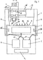
- the device has one Frame 1, one designed as a workpiece holder Machine table 2, which is attached to the frame, a tool stand 3 designed as a portal, a Bearing device 4, a processing device 5, a Clamping device 6, each a feed source 7 and 8 for the storage device and the tensioning device and a Control device 9.
- the tool stand 3 in on opposite sides of the machine table 2 slidably arranged.
- the tool stand has two Columns 11, in which the bearing device 4 is arranged and a support 12 which consists of two plates.
- the bearing device 4 is a fluid bearing with a Storage medium made of water, oil or air.
- the Air storage facilities are above pipe or Hose lines 27 connected to the feed source 7.
- the as Workpiece holder-trained machine table 2 is a cuboid body made of natural stone or plastic.
- the Machine table 2 contains a clamping device that a formed on its top groove grid 43, one in Machine table formed chamber 41, a number of Through holes 42, which the chamber with the at the Top of the machine table 2 trained Groove grid 43 connects and includes a line 47 to to connect the chamber with the feed source 8 and one Perforated plate 44 with through holes 45, which the Covering area.
- the through holes 42 are like this arranged to be at the intersection of the grid 46 flow out.
- the through holes in the machine table 2 and in the perforated plate 44 are arranged in the same grid.
- FIG. 3 shows the clamping area 43 through Grooves 46 formed that are perpendicular to each other are arranged. It should be noted that instead of the grooves arranged at right angles to each other the grooves according to the invention in an oblique angle Grid, arranged in rows or in a circle can. Instead of negative pressure, according to the invention a refrigerant-fed device is used, which is built into the machine table.
Landscapes
- Engineering & Computer Science (AREA)
- Mechanical Engineering (AREA)
- Machine Tool Units (AREA)
- Electrical Discharge Machining, Electrochemical Machining, And Combined Machining (AREA)
- Jigs For Machine Tools (AREA)
- Workshop Equipment, Work Benches, Supports, Or Storage Means (AREA)
Applications Claiming Priority (3)
| Application Number | Priority Date | Filing Date | Title |
|---|---|---|---|
| CH276693 | 1993-09-14 | ||
| CH276693 | 1993-09-14 | ||
| EP94810256A EP0652075B1 (fr) | 1993-09-14 | 1994-05-03 | Dispositif d'usinage de pièces |
Related Parent Applications (1)
| Application Number | Title | Priority Date | Filing Date |
|---|---|---|---|
| EP94810256A Division EP0652075B1 (fr) | 1993-09-14 | 1994-05-03 | Dispositif d'usinage de pièces |
Publications (2)
| Publication Number | Publication Date |
|---|---|
| EP0963808A2 true EP0963808A2 (fr) | 1999-12-15 |
| EP0963808A3 EP0963808A3 (fr) | 2002-10-23 |
Family
ID=4241138
Family Applications (2)
| Application Number | Title | Priority Date | Filing Date |
|---|---|---|---|
| EP99117846A Withdrawn EP0963808A3 (fr) | 1993-09-14 | 1994-05-03 | Table de travail en forme de support de pièce pour usinage par enlèvement de copeaux de pièces |
| EP94810256A Expired - Lifetime EP0652075B1 (fr) | 1993-09-14 | 1994-05-03 | Dispositif d'usinage de pièces |
Family Applications After (1)
| Application Number | Title | Priority Date | Filing Date |
|---|---|---|---|
| EP94810256A Expired - Lifetime EP0652075B1 (fr) | 1993-09-14 | 1994-05-03 | Dispositif d'usinage de pièces |
Country Status (4)
| Country | Link |
|---|---|
| EP (2) | EP0963808A3 (fr) |
| AT (1) | ATE194534T1 (fr) |
| DE (2) | DE9407357U1 (fr) |
| ES (1) | ES2149857T3 (fr) |
Cited By (1)
| Publication number | Priority date | Publication date | Assignee | Title |
|---|---|---|---|---|
| DE102011008981A1 (de) | 2011-01-20 | 2012-07-26 | Rüdiger Schrott | Modular aufgebaute Aufspannplatte |
Families Citing this family (7)
| Publication number | Priority date | Publication date | Assignee | Title |
|---|---|---|---|---|
| EP0845325A1 (fr) | 1996-12-02 | 1998-06-03 | Huber Engineering AG | Dispositif pour l'usinage de pièces |
| DE10040277C2 (de) * | 2000-08-14 | 2003-08-28 | Lat Suhl Ag | Kreuztisch zur Bereitstellung von Bewegungen in einem zweidimensionalen Koordinatensystem |
| DE10260253A1 (de) † | 2002-12-20 | 2004-07-01 | Giesecke & Devrient Gmbh | Verfahren und Vorrichtung zur Herstellung von Stichtiefdruckplatten und damit hergestellte Druckplatte |
| CN102554662B (zh) * | 2011-12-22 | 2014-10-22 | 上海三一精机有限公司 | 工作台自定心及工件夹紧装置的控制方法 |
| CN103990993A (zh) * | 2014-05-14 | 2014-08-20 | 安徽机电职业技术学院 | 多件装夹多工位可旋转气动夹具 |
| CN105127806A (zh) * | 2015-09-15 | 2015-12-09 | 常熟理工学院 | 一种组合式多功能真空夹具 |
| CN105750934A (zh) * | 2016-05-04 | 2016-07-13 | 深圳市创世纪机械有限公司 | 数控机床的工作台和数控机床 |
Citations (1)
| Publication number | Priority date | Publication date | Assignee | Title |
|---|---|---|---|---|
| DE3838988C1 (en) | 1988-11-18 | 1989-12-07 | Heinz Mielenz Gmbh, Cnc-Bearbeitung, 7316 Koengen, De | Vacuum clamping device |
Family Cites Families (18)
| Publication number | Priority date | Publication date | Assignee | Title |
|---|---|---|---|---|
| US2959452A (en) * | 1956-08-08 | 1960-11-08 | Kearney & Trecker Corp | Slide and way structure |
| GB1059285A (en) * | 1964-06-03 | 1967-02-15 | Charles Churchill And Company | Slideway and sliding member system |
| GB1073442A (en) * | 1964-12-19 | 1967-06-28 | Rheinstahl Henschel Ag | Improvements in or relating to hydrostatic mountings used with longitudinally movable parts |
| US3495492A (en) * | 1969-05-05 | 1970-02-17 | Gerber Garment Technology Inc | Apparatus for working on sheet material |
| FR2050688A5 (fr) * | 1969-06-20 | 1971-04-02 | Sirugue Et Cie | |
| DE2346633A1 (de) * | 1973-09-17 | 1975-04-24 | Wotan Werke Gmbh | Fuehrung fuer relativ zueinander bewegbare maschinenteile |
| DD120705A1 (fr) * | 1975-06-20 | 1976-06-20 | ||
| DE2643206A1 (de) * | 1976-09-25 | 1978-03-30 | Basf Ag | Verwendung von nach fotopolymeren verfahren hergestellten koerpern mit oberflaechenstruktur zur flaechenhaften verteilung von unter- oder ueberdruck |
| FR2473925A1 (fr) * | 1980-01-21 | 1981-07-24 | Line Sa | Perfectionnement aux machines-outils, notamment aux fraiseuses type aviation, dites 5 axes |
| US4494433A (en) * | 1982-01-25 | 1985-01-22 | Gerber Garment Technology, Inc. | Apparatus for working on sheet material and having movable vacuum chamber |
| JPS6090646A (ja) * | 1983-10-22 | 1985-05-21 | Fanuc Ltd | 工作機械におけるパレツトクランプ装置 |
| JPS61152499A (ja) * | 1984-12-27 | 1986-07-11 | 大日本スクリ−ン製造株式会社 | 硬質板の吸着、保持方法及びその方法の実施に使用する軟質シ−ト |
| DE8703223U1 (fr) * | 1987-03-03 | 1987-04-16 | Modellbau Paul Apitz, 7913 Senden, De | |
| US4763420A (en) * | 1987-10-06 | 1988-08-16 | Brown & Sharpe Manufacturing Company | Base assembly for coordinate measuring machine |
| JPH04283037A (ja) * | 1991-03-07 | 1992-10-08 | Kitamura Mach Co Ltd | 工作機械 |
| JPH0690646A (ja) * | 1991-09-19 | 1994-04-05 | Michiyuki Okamura | ワンタッチウキの形成方法 |
| DE4132311A1 (de) * | 1991-09-27 | 1993-04-01 | Siemens Ag | Verfahren und vorrichtung zum trennsaegen von scheibenfoermigen bauteilen |
| ES1019199Y (es) * | 1991-11-04 | 1992-10-16 | Ona Electro-Erosion, S.A. | Estructura para maquina-herramienta, en particular maquina-herramienta de electroerosion. |
-
1994
- 1994-05-03 DE DE9407357U patent/DE9407357U1/de not_active Expired - Lifetime
- 1994-05-03 ES ES94810256T patent/ES2149857T3/es not_active Expired - Lifetime
- 1994-05-03 EP EP99117846A patent/EP0963808A3/fr not_active Withdrawn
- 1994-05-03 AT AT94810256T patent/ATE194534T1/de not_active IP Right Cessation
- 1994-05-03 EP EP94810256A patent/EP0652075B1/fr not_active Expired - Lifetime
- 1994-05-03 DE DE59409437T patent/DE59409437D1/de not_active Expired - Fee Related
Patent Citations (1)
| Publication number | Priority date | Publication date | Assignee | Title |
|---|---|---|---|---|
| DE3838988C1 (en) | 1988-11-18 | 1989-12-07 | Heinz Mielenz Gmbh, Cnc-Bearbeitung, 7316 Koengen, De | Vacuum clamping device |
Cited By (1)
| Publication number | Priority date | Publication date | Assignee | Title |
|---|---|---|---|---|
| DE102011008981A1 (de) | 2011-01-20 | 2012-07-26 | Rüdiger Schrott | Modular aufgebaute Aufspannplatte |
Also Published As
| Publication number | Publication date |
|---|---|
| EP0652075B1 (fr) | 2000-07-12 |
| EP0963808A3 (fr) | 2002-10-23 |
| ES2149857T3 (es) | 2000-11-16 |
| EP0652075A3 (fr) | 1996-07-03 |
| EP0652075A2 (fr) | 1995-05-10 |
| DE59409437D1 (de) | 2000-08-17 |
| DE9407357U1 (de) | 1994-09-01 |
| ATE194534T1 (de) | 2000-07-15 |
Similar Documents
| Publication | Publication Date | Title |
|---|---|---|
| DE10297131B4 (de) | Düse für kohärente Strahlen bei Schleifanwendungen | |
| DE20105248U1 (de) | Fräs-/Schleifmaschine zur Herstellung von zahnmedizinischen Werkstücken | |
| DE3429842A1 (de) | Werkzeughaltevorrichtung | |
| CH655886A5 (de) | Laserstrahl-werkzeugmaschine. | |
| EP0963808A2 (fr) | Table de travail en forme de support de pièce pour usinage par enlèvement de copeaux de pièces | |
| DE3320598C2 (de) | Werkzeugmaschine mit einer Vorrichtung zum Entfernen von Bearbeitungsrückständen | |
| EP0936028A2 (fr) | Dispositif de superfinition de surfaces usinées | |
| DE10309456A1 (de) | Vorrichtung und Verfahren zur Oberflächenbearbeitung eines Werkstückes | |
| CH670417A5 (fr) | ||
| DE3149903C2 (de) | Vorrichtung zum Bearbeiten von Bauelementen aus Stein | |
| DE3443398A1 (de) | Niederhalter fuer werkstuecke, insbesondere an fraesmaschinen | |
| CH662077A5 (de) | Spannvorrichtung zur bearbeitung von werkstuecken. | |
| DE20101996U1 (de) | Vorrichtung zur Laserbearbeitung von Werkstücken | |
| EP0845325A1 (fr) | Dispositif pour l'usinage de pièces | |
| DE3002468A1 (de) | Verfahren und vorrichtung zur oberflaechenbearbeitung von leichtbauwaben | |
| DE2620477A1 (de) | Vertikalschleif- oder -poliermaschine | |
| DE29918968U1 (de) | Vorrichtung zum Durchlaufbearbeiten von platten- oder streifenförmigen Werkstücken | |
| DE1652707A1 (de) | Zum Beispiel nach Art eines Bohrwerkes wirkende Vorrichtung zur Bearbeitung von Werkstuecken | |
| DE10246082A1 (de) | Verfahren und Vorrichtung zur Paketbearbeitung von Dünnblechen und dünnwandigen, einfach oder doppelt gekrümmten Platten oder Schalen | |
| DE19849833B4 (de) | Werkzeugmaschine | |
| DE2322825A1 (de) | Schneidwerkzeug und verfahren zur anformung der schneidkanten desselben | |
| DE3018760C2 (de) | Maschinenstruktur mit Führungsvorrichtung für numerisch gesteuerte Werkzeugträger | |
| DE2217605A1 (de) | Verfahren und einrichtung zum freihalten von an einer spanabhebenden werkstueck-bearbeitungsmaschine befindlichen passflaechen von spaenen | |
| DE809288C (de) | Werkzeugschleifmaschine | |
| DE102021001502A1 (de) | Werkstückspannvorrichtung |
Legal Events
| Date | Code | Title | Description |
|---|---|---|---|
| PUAI | Public reference made under article 153(3) epc to a published international application that has entered the european phase |
Free format text: ORIGINAL CODE: 0009012 |
|
| AC | Divisional application: reference to earlier application |
Ref document number: 652075 Country of ref document: EP |
|
| AK | Designated contracting states |
Kind code of ref document: A2 Designated state(s): AT BE DE ES FR GB IT NL PT SE |
|
| PUAL | Search report despatched |
Free format text: ORIGINAL CODE: 0009013 |
|
| AK | Designated contracting states |
Kind code of ref document: A3 Designated state(s): AT BE DE ES FR GB IT NL PT SE |
|
| RIC1 | Information provided on ipc code assigned before grant |
Free format text: 7B 23Q 1/01 A, 7B 23Q 1/38 B, 7B 23Q 3/06 B, 7B 23Q 3/08 B, 7B 25B 11/00 B |
|
| RAP1 | Party data changed (applicant data changed or rights of an application transferred) |
Owner name: HUBER, EDUARD |
|
| AKX | Designation fees paid |
Designated state(s): AT BE DE ES FR GB IT NL PT SE |
|
| 17P | Request for examination filed |
Effective date: 19990910 |
|
| 17Q | First examination report despatched |
Effective date: 20041215 |
|
| STAA | Information on the status of an ep patent application or granted ep patent |
Free format text: STATUS: THE APPLICATION IS DEEMED TO BE WITHDRAWN |
|
| 18D | Application deemed to be withdrawn |
Effective date: 20050426 |