EP0962951A2 - Temperaturschalter, insbesondere einstellbarer Temperaturregler - Google Patents
Temperaturschalter, insbesondere einstellbarer Temperaturregler Download PDFInfo
- Publication number
- EP0962951A2 EP0962951A2 EP99110331A EP99110331A EP0962951A2 EP 0962951 A2 EP0962951 A2 EP 0962951A2 EP 99110331 A EP99110331 A EP 99110331A EP 99110331 A EP99110331 A EP 99110331A EP 0962951 A2 EP0962951 A2 EP 0962951A2
- Authority
- EP
- European Patent Office
- Prior art keywords
- spring
- expansion
- lever
- power transmission
- buffer
- Prior art date
- Legal status (The legal status is an assumption and is not a legal conclusion. Google has not performed a legal analysis and makes no representation as to the accuracy of the status listed.)
- Granted
Links
Images

Classifications
-
- H—ELECTRICITY
- H01—ELECTRIC ELEMENTS
- H01H—ELECTRIC SWITCHES; RELAYS; SELECTORS; EMERGENCY PROTECTIVE DEVICES
- H01H36/00—Switches actuated by change of magnetic field or of electric field, e.g. by change of relative position of magnet and switch, by shielding
-
- H—ELECTRICITY
- H01—ELECTRIC ELEMENTS
- H01H—ELECTRIC SWITCHES; RELAYS; SELECTORS; EMERGENCY PROTECTIVE DEVICES
- H01H37/00—Thermally-actuated switches
- H01H37/02—Details
- H01H37/32—Thermally-sensitive members
- H01H37/36—Thermally-sensitive members actuated due to expansion or contraction of a fluid with or without vaporisation
- H01H37/38—Thermally-sensitive members actuated due to expansion or contraction of a fluid with or without vaporisation with bellows
-
- H—ELECTRICITY
- H01—ELECTRIC ELEMENTS
- H01H—ELECTRIC SWITCHES; RELAYS; SELECTORS; EMERGENCY PROTECTIVE DEVICES
- H01H13/00—Switches having rectilinearly-movable operating part or parts adapted for pushing or pulling in one direction only, e.g. push-button switch
- H01H13/02—Details
- H01H13/12—Movable parts; Contacts mounted thereon
- H01H13/20—Driving mechanisms
-
- H—ELECTRICITY
- H01—ELECTRIC ELEMENTS
- H01H—ELECTRIC SWITCHES; RELAYS; SELECTORS; EMERGENCY PROTECTIVE DEVICES
- H01H3/00—Mechanisms for operating contacts
- H01H3/32—Driving mechanisms, i.e. for transmitting driving force to the contacts
-
- Y—GENERAL TAGGING OF NEW TECHNOLOGICAL DEVELOPMENTS; GENERAL TAGGING OF CROSS-SECTIONAL TECHNOLOGIES SPANNING OVER SEVERAL SECTIONS OF THE IPC; TECHNICAL SUBJECTS COVERED BY FORMER USPC CROSS-REFERENCE ART COLLECTIONS [XRACs] AND DIGESTS
- Y10—TECHNICAL SUBJECTS COVERED BY FORMER USPC
- Y10T—TECHNICAL SUBJECTS COVERED BY FORMER US CLASSIFICATION
- Y10T29/00—Metal working
- Y10T29/49—Method of mechanical manufacture
- Y10T29/49002—Electrical device making
- Y10T29/49105—Switch making
Definitions
- the invention relates to a temperature switch, in particular an adjustable temperature controller, according to the generic term of claim 1.
- a generic temperature switch has a temperature sensitive Expansion element that has a power transmission acts on a switch spring of a snap switch. There is also an overload protection for the switching spring intended.
- the overload protection has at least one Buffer with the force transmission between the expansion element and switching spring cooperates, especially in the Power flow of the power transmission is installed.
- the buffer is above one of the actuating force of the switch spring in Limit force assigned to the switching point can be changed or compliant while he is below the limit temperature in can be essentially unyielding or rigid.
- Such a temperature switch is from DE 196 27 969 known. He has one as a force translation or force translator Power transmission element serving rocker arm, the from an expansion box of a thermo-hydraulic expansion system via an intermediate buffer element is pressed and which acts on the snap switch.
- the Buffer element consists of a closed box that is made of two pot-shaped, overlapping halves, between which a compression spring is biased.
- the buffer element transmits the switching force of the expansion socket in the Force range in which the snap spring actuation takes place completely rigid while going beyond one overload becomes compliant and telescopes.
- a metallic can half of the three-part Buffer element is firmly attached to the expansion socket.
- the spring is then inserted to generate a preload using the other can part and the can parts are connected to each other by bending claws. At the further assembly will then be on the expansion element attached buffer element placed on the operating lever.
- This system works fine, but is in the Manufacturing, especially during assembly, is quite complex.
- the invention has for its object a temperature switch of the type mentioned at the outset, which is inexpensive is manufacturable and easy to assemble.
- the buffer and the power transmission form a designable as a buffered power transmission unit Unit, i.e. a unit that contains both the Power transmission functions between expansion element and switching spring, as well as the function of the buffer, which below its limit force like a rigid element of Power transmission works, but one above its limit force brings certain flexibility into the power transmission.
- the Invention enables complete, essentially through the load-dependent buffered or damped power transmission unit and the snap mechanism formed as snap mechanism an assembly, for example on a base of the Temperature switch regardless of the expansion system pre-assemble, for further assembly the expansion element comprehensive assembly put on and adjusted if necessary without attachment between the expansion element and snap mechanism must be provided.
- the power transmission has a lever device with at least one lever on the preferably one-sided in the manner of a cutting edge bearing is supported and / or has a lever arm that on the Switching spring, preferably with point contact, acts.
- a lever is a simple power transmission element whose power transmission over the effective Lever lengths can be selected.
- the power transmission can be 1: 1 take place, but preferably strengthening or reducing force Act.
- a translation lever can be used to increase the Snap spring sensitivity can be used.
- a special one simple embodiment is with a substantially L-shaped Lever given either on a switch spring carrier hung and supported or in a recess of the Switch spring carrier or in a separate recess for example, the switch base can be performed.
- a Stop is provided on which the lever, in particular the lever arm acting on the switch spring after overcoming the switching point for the switching spring preferably supports directly.
- the support can move the Release the lever after the desired switching process has expired is and far before the elastic range of the spring is exceeded and this if necessary by overpressing and thus associated plastic deformation are permanently damaged could.
- the stop is preferably by a projection a shift spring support, in particular through the shift tongue abutment, educated.
- it is also possible to Stop by a projection or section of the switch base to form and / or if necessary at the by the stop path-limited lever arm or another point on the lever provide a separate approach to support.
- the Buffer at least one preloaded, in the spring direction, especially in the direction of expansion, self-captivating or includes self-limiting spring element.
- the spring element is preferably in shape a biased in the opening direction of your legs, preferably U-shaped bow spring, the opening is limited by a spring stop. Below one sufficient to compress the legs Such a spring element is essentially a load rigid or dimensionally stable, while above a limit force let the thighs squeeze.
- Integrated path limitation can have at least one on one Spring section, e.g.
- hook attached to one leg be provided, in particular the shape of a bending tab may have.
- This can be on another spring section or grip behind the provided projection.
- the contact surface at the stop is preferably small, for example linear or punctiform, whereby the Spring length or width in the stroke-limited state very much exactly definable and also with multiple overloading and subsequent relief of the spring element reproducible is.
- the load-dependent buffered or damped power transmission unit which is also used as a buffer lever assembly can be called a single, is a one-piece component, in particular a spring plate bent part.
- This can act as both lever sections also have sections acting as buffers, especially one Section that forms a self-captivating bow spring.
- the Lever or lever section can have an L-shape and for example two, forming a cutting edge bearing, in lateral Have spaced support legs.
- a self-limiting spring element forming the buffer lie for example one leg of a bow spring with the support leg sections adjacent on both sides first forms a three-pronged fork arrangement and the appropriate tines to complete a steamed Shift paddle bent in opposite directions accordingly become. Laterally protruding projections of the fork part can then by bent retaining tabs on the sides of the behind the other leg of the U-shaped bow spring and thereby bring about the self-restraint of the bow spring.
- Permanently reliable temperature switches can in particular then be created when the expansion unit an expansion box of a thermo-hydraulic expansion system includes. Thanks to the invention it is possible that the Expansion unit, especially the one also called Diastat Expansion box, when the temperature switch is assembled in unconnected system contact with the buffer lever unit or one resilient on a housing of the switch attached insulating piece stands.
- the touch contact can be made during the assembly of the switch without separate connection means, such as screws or solder joints, must be provided.
- Such is correspondingly easy Temperature switch can also be removed in order to replace defective parts.
- the buffer lever assembly via a preferably pressure-rigid insulating piece made of electrically insulating, in particular ceramic material, supported on the expansion unit.
- the insulating piece can be detachably or permanently attached to the assembly and can be installed together with it.
- the insulating piece can also be movable, in particular resilient, for example via a bow spring, attached to the housing and thus Be part of the housing assembly.
- a particularly flat design can be achieved if instead of the also possible expansion box with two bowl-shaped sheet metal membranes and central connection nipple a flat membrane is used for a capillary tube at the the capillary tube in the area of the peripheral edge of the Leads essentially radially directly into the interior of the can, without the need for a separate connection nipple.
- the buffer with a the power transmission firmly connectable or connected is a separate buffer element, which before assembly of the temperature switch with the power transmission, in particular the rocker arm, to form a buffered power transmission unit preferably insoluble, for example by a rivet connection or welding.
- the preferably variable-length buffer element can be used as Pressure element be formed, the pressure load below the intended limit force is essentially dimensionally stable and reversible above the limit force, for example is telescopic, compressible.
- the three-part buffer elements known from DE 196 27 969 with two, enclosing a prestressed compression spring, interlocking can parts are used, a can part can be attached to the rocker switch.
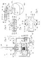
- the longitudinal section in Fig. 1 shows the switching components of a first embodiment of a temperature controller 1, the with a thermohydraulic expansion system 2 cooperates.
- the expansion system includes a schematically indicated one Temperature sensor 3 in the form of an expansion liquid filled tube, which via a capillary tube 4 with an expansion element in the form of an expansion box 5 connected is.
- the expansion box consists of two bowl-shaped, corrugated sheet membranes attached to their in the figure edges bent upwards by welding or soldering are connected to each other in a pressure-tight manner.
- About one in the Shell of the expansion socket in a centrally arranged connection nipple 6 is the capillary tube 4 with the inside of the between the corrugated sheet metal shells formed cavity.
- nipple 6 On the top of the nipple 6 is integral with the nipple Retaining pin 7 provided in a hollow setting shaft 8 is. This has an external thread 9 with an internal thread cooperates, which is provided in a sleeve 10 is that in the top 12 of a box-shaped Metal housing 13 is integrally formed with this.
- the Adjustment shaft 8 is flattened on one side by an adjustment button non-rotatably. There is an adjusting screw in it 14 provided on the retaining bolt 7 to its vertical Acts adjustment.
- the housing 13 is made of sheet metal and has the shape of a rectangular, partly openwork box whose top 12 mounting brackets 15 for installing the Temperature controller are formed.
- the bottom of the case will of a base part or base 16 made of temperature-resistant, dimensionally stable and electrically insulating material, for example Steatite or other ceramic material, educated.
- the housing 13 is by twisting tabs 17 set.
- the plate-shaped base part 16 carries a snap switch 20.
- This has a switching spring 21 on a switching spring carrier 22 is attached.
- the switch spring carrier 22 is a relatively small, solid sheet metal part, which is a switch tongue abutment 23 in the form of an upward bend having.
- the switch-off position is at the front end of the switch spring one formed from the base part and forming a counter bearing Projection 26 on.
- the switch is in the on position Contact 25 on a counter contact 27, which is on a Mating contact bridge 28 is located under one by the spring provided contact pressure.
- the snap switch carrier 22 and the mating contact bridge 28 create fastening lugs by U-shaped design on the one hand as twisting tabs 29 and on the other hand as well flat tabs fixed by twisting 19 are formed, via which the electrical connection the underside of the plate-shaped base part.
- the snap switch 20 is over with the expansion element 5 a lever device 30 which acts as a power transmission mechanically coupled in such a way that a Expansion of the expansion box 5 over a predeterminable vertical Dimension to an opening of the contact 25, 27th leads.
- the lever device 30 comprises a buffered or damped rocker switch 31, the structure of which is related Figures 2 to 4 is explained in more detail. Your is a ceramic Insulated button 32 assigned to the top of the rocker switch is attached and is spherical with its upward curved top 33 in the middle of the large flat Underside 34 on the underside of the expansion socket 5 attached metal disc 35 on a small punctiform Supports the contact point.
- the rigid and electric insulating material of the on a vertically protruding fastening tab 36 of the rocker switch 31 attached ceramic Knob 32 ensures a rigid transmission of the Vertical movement of the bottom of the can onto the rocker switch 31 and creates the necessary electrical insulation between live parts of the snap mechanism 20, 30 and Expansion unit 5.
- the upward curved edges of the Expansion boxes also promote adequate compliance electrical distances between the snap mechanism and the expansion system. That through the flat underside of the metal disc 35 large, flat contact surface provided for the curved top of the insulating piece 32 ensures that the pressure ratios and thus the switching accuracy of the Regulator essentially independent of small position tolerances the expansion unit.
- the switching rocker designed as a one-piece spring steel bent part 31 combines several functions within the Power transmission and overpressure protection, it includes one essentially L-shaped, as a transmission transmission lever acting lever section 40 and one piece with this trained, acting as a buffer U-shaped curved Bow spring 41, the legs 42, 43 in the opening direction the bow spring are biased and the stop is limited up to a predetermined maximum vertical dimension can open. So it is a one-piece rocker switch with integrated overload damper.
- the lever or lever section 40 has to create clearer Pressure ratios with a central, bead-shaped Expression 45 provided lever arm 46 with which he punctiform on an actuation point 47 on a cross extending bead of the switching spring acts.
- lever arm 46 On the opposite End of the lever, which is wider than long, are with large lateral distance from each other two at right angles provided below bent support legs 48, 49, the form lower ends of the cutting edge bearing 50 by being on the Surface of the base part 16 are supported.
- Fig. 3 is by a curved lower edge of the Support legs 48, 49 ensure that clear support conditions given are.
- the two support legs protrude from both sides a recess in the side edge of the switch spring support 22 into it so that the support legs are guided in it.
- Protruding Lugs 51 on the inside of the support legs 48, 49 are barb-like and provide after the Lever 40 pressed under pressure from above into the recesses is for a safeguard against lifting the lever.
- the rocker switch 41 is not over its entire load range essentially rigid, conventional lever, but is able to be below a predefinable one Limit force essentially rigid or dimensionally stable be resilient or resilient above the limit force to be a certain decoupling of the through the Expansion box 5 caused force from the lever arm 46 and / or from the switch spring.
- This buffer function will created by the stop spring 41 which opens to a limited extent, which is a self-captivating or self-limiting spring element forms.
- the bow spring 41 sits symmetrically to create Pressure conditions symmetrical between the support legs 48, 49.
- the by a transition into the expression 45, wide reinforcement bead 52 stabilized against bending Lower leg 42 is a flat, one-piece extension of the lever arm 46.
- the lower leg 42 goes with one U-shaped bend 53 in when the spring is fully open ( Figures 1 to 3) running parallel to the lower leg, also stabilized by an indented bead 54 Thigh 43 over, from the middle of the fastening tab 36 is bent up.
- the bow spring 41 has one in the opening direction of its legs Preload that is certainly greater than the limit force, those in the area of the tab 36 or the projections 57, 58 essentially perpendicular to the leg longitudinal direction attacks when the actuating force of the switching spring on their Switching point is reached.
- This interpretation of the spring strength causes the bow spring 41 under pressure from the Expansion box 5 at least as long as a rigid power transmission element acts until the switching point of the switching spring overcome and the contact 25, 27 is open.
- additional forces on the bow spring legs can in contrast cause a compression of the legs, so that in Force flow between expansion element 5 and switch spring one reversible compliance against overpressure given is.
- the assembly of a temperature controller according to the invention is particularly simple, since for snapping the snap mechanism 20, 30 on the base part 16 only simple plugging and bending processes must be made and the connection of the Snap mechanism with the expansion unit 5 only through simple system contact between the large flat Bottom 34 of the metal disc 35 and the dome-shaped Top 33 of the insulating button 32 is created. Even at small lateral position inaccuracies of the expansion unit the switching conditions change relative to the power transmission practically not.
- the complete snap mechanism can be used as an assembly on the base base 16 pre-assembled.
- the parts of the Snap switch on the base part 16 by plugging in corresponding slots and twisting of the tabs 19 and the twist tabs 17, 29 set.
- the one piece Bent sheet metal part very easy-to-use rocker switch 31 is pressed from above over the snap switch carrier and engages due to a snap lock formed by the lugs 51 there one.
- the insulating button 32 can be before or after the installation of the rocker switch on the mounting bracket 36 be placed, with a fastening against lifting off the tab 36 is not necessary because in the assembled Condition and operation of the assembled switch Button 32 is only subjected to pressure.
- the filled and soldered component sensor / capillary tube / expansion socket 5 is attached to the retaining bolt 7. It can use standardized expansion elements or diastats be used as the expansion unit, except for the Need a pressure surface for the insulator 32 provide, not structurally adapted to the snap mechanism must become.
- the adjustment is made using the adjustment screw 14.
- the setting shaft 8 for setting a certain temperature rotated so that the thread 9, 10th the expansion box 5 in a certain position along the Axis 60 of the adjusting shaft is brought.
- the switching spring 21 is already more or less biased and more or less close to their switching point brought up.
- the temperature sensor 3 When the temperature sensor 3 is warmed up, it expands Expansion fluid contained in the sensor and expands the Expansion box 5, so that the metal disc 35 after moves down and the lever 46 counter to that by the switching spring applied force pivoted clockwise.
- the switching spring is supported in such a way that unloaded state of the switching spring the outer end with the Contact 25 is present on counter contact 27, i.e. the switch closed is.
- the one connected via the tabs Circuit is closed via the snap spring and the Switch is on.
- the base part 16 or the switch spring support 22 may have recesses have, in which the tabs 55, 56 can dip, unless the surface level of the base part is constructive should already be deep enough.
- the maximum press-over distance the bow spring can by the height of the frame opening in the Tab be limited. This required amount in turn will of the maximum expansion or the maximum stroke of the Membrane predetermined.
- the expansion box 5 contracts and the strap spring 41, which acts as a buffer, returns to the Figures 1 to 3 shown initial shape with a defined maximum Opening width of the legs elastic back.
- the buffer-lever unit created by the one-piece rocker switch 31 from shift lever 40 and buffer 41 is therefore one absolutely pressure-rigid in the operating state and only when overloaded yielding, but then exactly in his original form moving back one Power transmission between expansion socket and snap switch.
- the spring elasticity in this buffer only becomes effective if the switching has already taken place and is only for Overload protection primarily of the switching spring, but if necessary also the rocker switch itself and the expansion unit.
- the embodiment of a temperature switch shown in FIG. 5 65 is distinguished from that shown in FIG. 1 Embodiment by a particularly low height.
- a flatter, electrically insulating ceramic body 69 provided that when the temperature switch is assembled with its domed top in punctiform pressure contact with a flat underside a metal disc 70 stands on the underside of a Flat membrane expansion socket 71 is present.
- plate-shaped expansion box 5 according to FIG. 1 does that Capillary tube in the radial direction in the plane of the flat membrane directly into the inside of the corrugated, flat sheet metal halves the expansion box 71.
- one Temperature controller 75 differs from those before described embodiments essentially by the Shape of the one-piece rocker switch of the buffer-lever unit and by attaching the electrical insulation between Snap mechanism and expansion unit, you will the example an expansion unit with the edge bent upwards, Similar to Fig. 1 described, but it can also be a flat membrane can be used according to the type of membrane in Fig. 5.
- the rocker switch 76 has the leg length essentially unchanged the bow spring compared to the ones previously described Embodiments of the U-bend 77 extended lever section 78, so that the cutting edge bearing 79 Support legs 80, 81 away from the adjustment axis 82 into the Area of the U-bend. In the area of the adjustment axis is one instead of the retaining tab for the insulating piece Dome-shaped upward expression 83 of the upper Bow leg trained.
- the shift paddle from the expansion unit 84 is electrical insulating insulating piece 85 is not on the rocker switch attached, but is of a cross section of FIG. 7 easily recognizable bow spring 86 worn, the free Thighs on opposite, outwardly protruding Support the horizontal beads 87, 88 of the housing 89.
- the Insulator 85 has a flat bottom surface 89 with which it is supported point-by-point on the calotte 83 of the rocker switch, and an axial blind hole opening 90, in which is a bolt-shaped, vertical neck 91 on the underside the expansion unit 84 is inserted with a precise fit.
- the insulating button 85 is thus by means of a resilient sheet metal part 86 axially pressed against the membrane 84 and is by its movable attachment to the housing part of the assembly assembly "Casing". If the bow spring together with the insulating piece in inserted the housing and subsequently also the expansion unit is installed, then one can by the bow spring 86th provided, upward axial preload any axial play in the area of the adjustment unit eliminate what can increase the setting accuracy.
Abstract
Description
- Fig. 1
- einen Längsschnitt durch eine Ausführungsform eines erfindungsgemäßen Temperaturreglers,
- Fig. 2(a)
- eine Seitenansicht einer als einstückiges Blech-Biegeteil ausgebildeten Puffer-Hebel-Einheit,
- Fig. 2(b)
- eine vergrößerte Detailansicht des eingekreisten Bereichs in Fig. 2(a),
- Fig. 3
- eine Vorderansicht der Puffer-Hebel-Einheit von Fig. 2,
- Fig. 4
- eine Draufsicht auf die Puffer-Hebel-Einheit von Fig. 2 im Schnitt entlang Linie IV-IV in Fig. 2(a),
- Fig. 5
- eine andere Ausführungsform eines Temperaturreglers mit einer Flachmembran-Ausdehnungsdose,
- Fig. 6
- eine weitere Ausführungsform eines Temperaturreglers mit einer anderen, einstückigen Puffer-Hebel-Einheit und einem dem Gehäuse zugeordneten Isolierstück im Längsschnitt und
- Fig. 7
- einen Querschnitt durch die Ausführungsform nach Fig. 7.
Claims (10)
- Temperaturschalter, insbesondere einstellbarer Temperaturregler, mit einem Ausdehnungselement, das über eine Kraftübersetzung auf eine Schaltfeder eines Schnappschalters wirkt, und mit einer Überlastsicherung für die Schaltfeder, wobei die Überlastsicherung mindestens einen Puffer aufweist, der mit der Kraftübersetzung zusammenwirkt und der oberhalb einer der Betätigungskraft der schaltfeder im Schaltpunkt zugeordneten Grenzkraft formveränderbar ist, dadurch gekennzeichnet, daß die Kraftübersetzung und der Puffer eine Baueinheit bilden.
- Temperaturschalter nach Anspruch 1, dadurch gekennzeichnet, daß die Kraftübersetzung eine Hebeleinrichtung (30) mit mindestens einem Hebel (40) aufweist, der vorzugsweise einseitig nach Art einer Schneidenlagerung abgestützt ist und/oder der einen Hebelarm (46) aufweist, der auf die Schaltfeder (21), vorzugsweise an einer punktförmigen Betätigungsstelle (47), einwirkt.
- Temperaturschalter nach dem Oberbegriff von Anspruch 1, insbesondere nach Anspruch 1 oder 2, dadurch gekennzeichnet, daß ein Anschlag (23) vorgesehen ist, an dem sich ein Hebel (40), insbesondere der auf die schaltfeder (21) einwirkende Hebelarm (46), nach Überwindung des Schaltpunktes für die Schaltfeder unmittelbar abstützt, wobei vorzugsweise der Anschlag durch einen Vorsprung (23) eines Schaltfederträgers (22) gebildet wird.
- Temperaturschalter nach einem der vorhergehenden Ansprüche, dadurch gekennzeichnet, daß der Puffer mindestens ein vorgespanntes, in Federrichtung selbstfesselndes Federelement umfaßt, insbesondere in Form einer in Öffnungsrichtung ihrer schenkel (42, 43) vorgespannten, anschlagsbegrenzt öffnenden Bügelfeder (41).
- Temperaturschalter nach Anspruch 4, dadurch gekennzeichnet, daß das selbstfesselnde Federelement (41) an dem Hebel befestigt, insbesondere einstückig mit dem Hebel (40) ausgebildet ist, wobei vorzugsweise das selbstfesselnde Federelement symmetrisch zwischen Stützschenkeln (48, 49) eines L-förmigen Hebels angeordnet ist und/oder daß zur Selbstfesselung des Federelementes mindestens ein an einem Federabschnitt vorgesehener Haken, insbesondere eine einstückig mit einem schenkel (43) der Bügelfeder (41) ausgebildete Biegelasche (55, 56), vorgesehen ist, der einen an einem anderen Federabschnitt, insbesondere dem anderen Schenkel (42) , vorgesehenen Vorsprung (57, 58) hintergreift, vorzugsweise derart, daß sich der Haken (55, 56) unter Vorspannung des Federelementes kleinflächig an dem Vorsprung (57, 58) abstützt.
- Temperaturschalter nach einem der vorhergehenden Ansprüche, dadurch gekennzeichnet, daß die Baueinheit aus Puffer und Kraftübersetzung, insbesondere Hebeleinrichtung (30), ein einstückiges Bauteil ist, insbesondere ein Federblech-Biegeteil.
- Temperaturschalter nach einem der vorhergehenden Ansprüche, dadurch gekennzeichnet, daß die Ausdehnungseinheit eine Ausdehnungsdose (5; 71) eines thermo-hydraulischen Ausdehnungssystems umfaßt, wobei vorzugsweise die Ausdehnungsdose als Flachmembran-Ausdehnungsdose (71) ausgebildet ist und/oder daß die Ausdehnungseinheit, insbesondere die Ausdehnungsdose (5; 71; 84), im zusammengebauten Zustand des Temperaturschalters in unverbundenem Anlagekontakt mit der Baueinheit aus Puffer und Kraftübersetzung oder einem am Gehäuse (89) beweglich befestigten Isolierstück (85) steht.
- Temperaturschalter nach einem der vorhergehenden Ansprüche, dadurch gekennzeichnet, daß die Baueinheit aus Puffer und Kraftübersetzung elektrisch von der Ausdehnungseinheit isoliert ist, wobei sie sich vorzugsweise über ein Isolierstück (32; 69; 85) aus elektrisch isolierendem, insbesondere keramischen Material, an der Ausdehnungseinheit (5; 71; 84) abstützt.
- Temperaturschalter nach Anspruch 8, dadurch gekennzeichnet, daß das Isolierstück (32; 69) an der Baueinheit befestigt, insbesondere aufgesteckt ist oder daß das Isolierstück (85) beweglich am Gehäuse (89) befestigt ist, wobei insbesondere ein sich am Gehäuse abstützendes, das Isolierstück tragendes Federelement (86) vorgesehen ist, das das Isolierstück an die Ausdehnungseinheit andrückt.
- Temperaturschalter nach einem der vorhergehenden Ansprüche, dadurch gekennzeichnet daß der Ausdehnungseinheit eine ebene Anlagefläche (34; 89) zugeordnet ist, an der sich die Baueinheit aus Puffer und Kraftübersetzung, mit einer konvex gekrümmten Stützfläche (33; 83) im wesentlichen punktförmig abstützt.
Priority Applications (1)
| Application Number | Priority Date | Filing Date | Title |
|---|---|---|---|
| SI9930562T SI0962951T1 (en) | 1998-06-04 | 1999-05-28 | Thermal switch, in particular adjustable temperature controller |
Applications Claiming Priority (2)
| Application Number | Priority Date | Filing Date | Title |
|---|---|---|---|
| DE19824871 | 1998-06-04 | ||
| DE19824871A DE19824871A1 (de) | 1998-06-04 | 1998-06-04 | Temperaturschalter, insbesondere einstellbarer Temperaturregler |
Publications (3)
| Publication Number | Publication Date |
|---|---|
| EP0962951A2 true EP0962951A2 (de) | 1999-12-08 |
| EP0962951A3 EP0962951A3 (de) | 2000-09-13 |
| EP0962951B1 EP0962951B1 (de) | 2004-02-18 |
Family
ID=7869820
Family Applications (1)
| Application Number | Title | Priority Date | Filing Date |
|---|---|---|---|
| EP99110331A Expired - Lifetime EP0962951B1 (de) | 1998-06-04 | 1999-05-28 | Temperaturschalter, insbesondere einstellbarer Temperaturregler |
Country Status (10)
| Country | Link |
|---|---|
| US (1) | US6064294A (de) |
| EP (1) | EP0962951B1 (de) |
| JP (1) | JP4408989B2 (de) |
| KR (1) | KR100612629B1 (de) |
| CN (1) | CN1158687C (de) |
| AU (1) | AU756777B2 (de) |
| DE (2) | DE19824871A1 (de) |
| ES (1) | ES2216375T3 (de) |
| SI (1) | SI0962951T1 (de) |
| TR (1) | TR199901257A3 (de) |
Cited By (5)
| Publication number | Priority date | Publication date | Assignee | Title |
|---|---|---|---|---|
| DE102004042829A1 (de) * | 2004-08-27 | 2006-03-02 | E.G.O. Elektro-Gerätebau GmbH | Silikonöl als Arbeitsfluid für einen Thermostat sowie ein solcher Thermostat |
| US7345572B2 (en) | 2004-02-24 | 2008-03-18 | Electrovac, Fabrikation Elektrotechnischer Spezialartikel Ges.M.B.H. | Temperature sensor |
| DE102015207132A1 (de) | 2015-04-20 | 2016-10-20 | E.G.O. Elektro-Gerätebau GmbH | Ventilanordnung und Verfahren zum Betrieb eines Gasbackofens mit einer Ventilanordnung |
| DE102016212329A1 (de) | 2016-07-06 | 2018-01-11 | E.G.O. Elektro-Gerätebau GmbH | Verfahren zur Steuerung eines Backofens und Backofen |
| DE102016219758B3 (de) | 2016-10-11 | 2018-04-05 | E.G.O. Elektro-Gerätebau GmbH | Verfahren zur Steuerung eines Backofens |
Families Citing this family (11)
| Publication number | Priority date | Publication date | Assignee | Title |
|---|---|---|---|---|
| CN100416734C (zh) * | 2006-04-17 | 2008-09-03 | 李德强 | 一种温控开关 |
| GB0717051D0 (en) * | 2007-09-01 | 2007-10-17 | Ceramaspeed Ltd | Temperature sensor |
| CN101826415B (zh) * | 2010-04-28 | 2012-05-30 | 陈永龙 | 小双断温控器 |
| DE102012106978B4 (de) * | 2012-07-31 | 2014-08-14 | Werner Reiter | Temperaturschalter sowie Verfahren zur Justierung eines Temperaturschalters |
| CN102867683A (zh) * | 2012-09-17 | 2013-01-09 | 江苏常恒集团自动控制器有限公司 | 一种单刀双掷温度控制器 |
| DE102013218014B4 (de) | 2013-09-09 | 2015-03-19 | E.G.O. Elektro-Gerätebau GmbH | Gasventileinrichtung und Gasgerät mit einer Gasventileinrichtung |
| DE102014216363A1 (de) | 2014-08-18 | 2016-02-18 | E.G.O. Elektro-Gerätebau GmbH | Gasventileinrichtung für ein Gasgerät und Gasgerät |
| ITUA20163851A1 (it) * | 2016-05-26 | 2017-11-26 | Termoregolatori Campini Corel S P A | Termostato a struttura semplificata |
| JP6662537B2 (ja) * | 2016-07-22 | 2020-03-11 | アルプスアルパイン株式会社 | スイッチ装置及び該スイッチ装置の製造方法 |
| DE102018203099A1 (de) * | 2018-03-01 | 2019-09-05 | E.G.O. Elektro-Gerätebau GmbH | Temperaturgesteuerte Vorrichtung zum Abschalten einer Heizeinrichtung |
| CN109192603A (zh) * | 2018-10-13 | 2019-01-11 | 合肥格尔美电气科技有限公司 | 机械压力式温度控制器联体指标轴 |
Citations (2)
| Publication number | Priority date | Publication date | Assignee | Title |
|---|---|---|---|---|
| DE3627695A1 (de) * | 1986-08-14 | 1988-02-25 | Teves Gmbh Alfred | Elektrohydraulische schaltvorrichtung |
| EP0818796A2 (de) * | 1996-07-11 | 1998-01-14 | E.G.O. ELEKTRO-GERÄTEBAU GmbH | Temperaturschalter, insbesondere einstellbarer Temperaturregler |
Family Cites Families (24)
| Publication number | Priority date | Publication date | Assignee | Title |
|---|---|---|---|---|
| US1903924A (en) * | 1930-03-06 | 1933-04-18 | Charles Tagliabue Mfg Co | Automatic control switch |
| US2821605A (en) * | 1955-10-11 | 1958-01-28 | Standard Thomson Corp | Control device |
| US3274362A (en) * | 1964-07-15 | 1966-09-20 | Wilcolator Co | Adjustable fluid pressure operated electric switch |
| US3354280A (en) * | 1966-02-08 | 1967-11-21 | Gen Electric | Condition responsive electric switch mechanism |
| AT308424B (de) * | 1971-04-30 | 1973-07-10 | Richard Fonovits Kommanditgese | Elektrischer Temperaturregler |
| DE2156509A1 (de) * | 1971-11-13 | 1973-05-17 | Eberle Werke Kg | Bimetalltemperaturregler mit sicherheitsabschaltung |
| US3820049A (en) * | 1973-10-11 | 1974-06-25 | Honeywell Inc | Condition control apparatus |
| DE2724527A1 (de) * | 1977-05-31 | 1978-12-14 | Emerson Electric Gmbh | Temperaturregler |
| DE2815987C2 (de) * | 1978-04-13 | 1986-02-06 | E.G.O. Elektro-Geräte AG, Zug | Temperaturregler |
| IT1110797B (it) * | 1979-01-29 | 1986-01-06 | Eaton Spa | Termostato,particolarmente a bimetallo,con interruttore di sicurezza |
| DE3223461C2 (de) * | 1982-06-23 | 1986-09-11 | Bosch-Siemens Hausgeräte GmbH, 7000 Stuttgart | Temperaturregler |
| DE3236255A1 (de) * | 1982-09-30 | 1984-04-05 | E.G.O. Elektro-Geräte Blanc u. Fischer, 7519 Oberderdingen | Elektrischer schnappschalter |
| DE3238955A1 (de) * | 1982-10-21 | 1984-04-26 | E.G.O. Elektro-Geräte Blanc u. Fischer, 7519 Oberderdingen | Temperaturschaltgeraet |
| US4626819A (en) * | 1985-04-17 | 1986-12-02 | Safeway Products, Inc. | Switch adjusting mechanism |
| JPS6396833A (ja) * | 1986-10-13 | 1988-04-27 | 株式会社 鷺宮製作所 | サ−モスタツトの設定温度調節装置 |
| US4791397A (en) * | 1987-06-30 | 1988-12-13 | Therm-O-Disc, Incorporated | Thermostatic switch construction |
| FR2618940B1 (fr) * | 1987-07-28 | 1995-06-02 | Vernet Procedes Sa | Perfectionnements aux thermocontacts a disque cloquant |
| JPH02195622A (ja) * | 1989-01-23 | 1990-08-02 | Matsushita Refrig Co Ltd | サーモスタット |
| EP0425752B1 (de) * | 1989-11-03 | 1994-06-08 | C.A.E.M. S.R.L. | Einstellbarer elektrischer Thermostat mit Temperaturkompensation |
| US5315281A (en) * | 1992-02-25 | 1994-05-24 | Tpi Corporation | Thermostatically controlled switch |
| JP2860517B2 (ja) * | 1993-04-09 | 1999-02-24 | 株式会社生方製作所 | 熱応動開閉器及びその製造方法 |
| US5311165A (en) * | 1993-04-21 | 1994-05-10 | Harper-Wyman Company | Modular electric/gas oven thermostat and assembly method |
| DE4435303A1 (de) * | 1994-10-01 | 1996-04-04 | Ego Italiana | Schnappschalter, insbesondere für Temperaturschalter |
| JPH09108612A (ja) * | 1995-10-16 | 1997-04-28 | Fuji Photo Film Co Ltd | 塗布方法及び装置 |
-
1998
- 1998-06-04 DE DE19824871A patent/DE19824871A1/de not_active Withdrawn
-
1999
- 1999-05-28 DE DE59908551T patent/DE59908551D1/de not_active Expired - Fee Related
- 1999-05-28 EP EP99110331A patent/EP0962951B1/de not_active Expired - Lifetime
- 1999-05-28 ES ES99110331T patent/ES2216375T3/es not_active Expired - Lifetime
- 1999-05-28 SI SI9930562T patent/SI0962951T1/xx unknown
- 1999-06-02 JP JP15493999A patent/JP4408989B2/ja not_active Expired - Fee Related
- 1999-06-03 US US09/325,218 patent/US6064294A/en not_active Expired - Fee Related
- 1999-06-03 KR KR1019990020539A patent/KR100612629B1/ko not_active IP Right Cessation
- 1999-06-04 TR TR1999/01257A patent/TR199901257A3/tr unknown
- 1999-06-04 AU AU33185/99A patent/AU756777B2/en not_active Ceased
- 1999-06-04 CN CNB991071697A patent/CN1158687C/zh not_active Expired - Fee Related
Patent Citations (2)
| Publication number | Priority date | Publication date | Assignee | Title |
|---|---|---|---|---|
| DE3627695A1 (de) * | 1986-08-14 | 1988-02-25 | Teves Gmbh Alfred | Elektrohydraulische schaltvorrichtung |
| EP0818796A2 (de) * | 1996-07-11 | 1998-01-14 | E.G.O. ELEKTRO-GERÄTEBAU GmbH | Temperaturschalter, insbesondere einstellbarer Temperaturregler |
Cited By (6)
| Publication number | Priority date | Publication date | Assignee | Title |
|---|---|---|---|---|
| US7345572B2 (en) | 2004-02-24 | 2008-03-18 | Electrovac, Fabrikation Elektrotechnischer Spezialartikel Ges.M.B.H. | Temperature sensor |
| DE102004042829A1 (de) * | 2004-08-27 | 2006-03-02 | E.G.O. Elektro-Gerätebau GmbH | Silikonöl als Arbeitsfluid für einen Thermostat sowie ein solcher Thermostat |
| DE102015207132A1 (de) | 2015-04-20 | 2016-10-20 | E.G.O. Elektro-Gerätebau GmbH | Ventilanordnung und Verfahren zum Betrieb eines Gasbackofens mit einer Ventilanordnung |
| EP3086039A1 (de) | 2015-04-20 | 2016-10-26 | E.G.O. ELEKTRO-GERÄTEBAU GmbH | Ventilanordnung und verfahren zum betrieb eines gasbackofens mit einer ventilanordnung |
| DE102016212329A1 (de) | 2016-07-06 | 2018-01-11 | E.G.O. Elektro-Gerätebau GmbH | Verfahren zur Steuerung eines Backofens und Backofen |
| DE102016219758B3 (de) | 2016-10-11 | 2018-04-05 | E.G.O. Elektro-Gerätebau GmbH | Verfahren zur Steuerung eines Backofens |
Also Published As
| Publication number | Publication date |
|---|---|
| CN1158687C (zh) | 2004-07-21 |
| TR199901257A2 (xx) | 2000-01-21 |
| CN1238543A (zh) | 1999-12-15 |
| DE59908551D1 (de) | 2004-03-25 |
| SI0962951T1 (en) | 2004-08-31 |
| KR20000005894A (ko) | 2000-01-25 |
| KR100612629B1 (ko) | 2006-08-14 |
| ES2216375T3 (es) | 2004-10-16 |
| DE19824871A1 (de) | 1999-12-09 |
| TR199901257A3 (tr) | 2000-01-21 |
| AU756777B2 (en) | 2003-01-23 |
| EP0962951B1 (de) | 2004-02-18 |
| AU3318599A (en) | 1999-12-16 |
| JP4408989B2 (ja) | 2010-02-03 |
| US6064294A (en) | 2000-05-16 |
| EP0962951A3 (de) | 2000-09-13 |
| JPH11353991A (ja) | 1999-12-24 |
Similar Documents
| Publication | Publication Date | Title |
|---|---|---|
| EP0962951B1 (de) | Temperaturschalter, insbesondere einstellbarer Temperaturregler | |
| CH370471A (de) | Druckknopfbetätigter Überstromschalter | |
| EP0225490B1 (de) | Temperaturbegrenzer | |
| EP0606264B1 (de) | Vakuumschalter mit einer antriebsvorrichtung und einer polantriebseinheit | |
| DE102019125453A1 (de) | Temperaturabhängiger Schalter | |
| DE2917557C2 (de) | Wärmeschutzschalter | |
| EP0268098B1 (de) | Elektro-Schaltgerät, insbesondere zur Leistungssteuerung | |
| DE1490739B1 (de) | Verfahren zum Einstellen der Betaetigungsbewegung eines Thermoschnappgliedes | |
| DE3526785C1 (de) | Druckknopfbetaetigter UEberstromschutzschalter | |
| EP0394693B1 (de) | Temperatur-Schaltgerät | |
| DE3333645A1 (de) | Temperaturbegrenzer fuer eine glaskeramikkocheinheit | |
| EP0818796B1 (de) | Temperaturschalter, insbesondere einstellbarer Temperaturregler | |
| DE102019128367B4 (de) | Temperaturabhängiger schalter | |
| EP0285927B1 (de) | Temperaturschalter | |
| DE2502579C2 (de) | Druckknopfbetaetigter ueberstromschalter mit thermischer ausloesung | |
| EP2332161B1 (de) | Miniatur-schutzschalter | |
| DE102019112074B4 (de) | Temperaturabhängiger Schalter | |
| EP2843680B1 (de) | Temperaturabhängiger Schalter | |
| DE4435303A1 (de) | Schnappschalter, insbesondere für Temperaturschalter | |
| EP2650897B1 (de) | Temperaturempfindlicher elektrischer Schalter und Verfahren zu dessen Herstellung | |
| DE102020121590A1 (de) | Verfahren zur Montage eines Abschirmelementes; Montageeinheit für das Verfahren und elektronisches Gerät mit Abschirmelement in thermisch aktivierbarer Abtrenneinrichtung | |
| DE2422684A1 (de) | Schnappschalter | |
| DE2735426B2 (de) | Elektrokochplatte mit einem Temperaturbegrenzer | |
| DE102023104836B3 (de) | Temperaturabhängiges Schaltwerk und temperaturabhängiger Schalter | |
| DE2056446A1 (de) | Ein Aus Schalter mit Freiauslosung |
Legal Events
| Date | Code | Title | Description |
|---|---|---|---|
| PUAI | Public reference made under article 153(3) epc to a published international application that has entered the european phase |
Free format text: ORIGINAL CODE: 0009012 |
|
| AK | Designated contracting states |
Kind code of ref document: A2 Designated state(s): DE ES FR GB GR IT SE |
|
| AX | Request for extension of the european patent |
Free format text: AL;LT;LV;MK;RO;SI |
|
| PUAL | Search report despatched |
Free format text: ORIGINAL CODE: 0009013 |
|
| AK | Designated contracting states |
Kind code of ref document: A3 Designated state(s): AT BE CH CY DE DK ES FI FR GB GR IE IT LI LU MC NL PT SE |
|
| AX | Request for extension of the european patent |
Free format text: AL;LT;LV;MK;RO;SI |
|
| 17P | Request for examination filed |
Effective date: 20010216 |
|
| AKX | Designation fees paid |
Free format text: DE ES FR GB GR IT SE |
|
| AXX | Extension fees paid |
Free format text: SI PAYMENT 20010216 |
|
| 17Q | First examination report despatched |
Effective date: 20021008 |
|
| GRAP | Despatch of communication of intention to grant a patent |
Free format text: ORIGINAL CODE: EPIDOSNIGR1 |
|
| GRAS | Grant fee paid |
Free format text: ORIGINAL CODE: EPIDOSNIGR3 |
|
| GRAA | (expected) grant |
Free format text: ORIGINAL CODE: 0009210 |
|
| AK | Designated contracting states |
Kind code of ref document: B1 Designated state(s): DE ES FR GB GR IT SE |
|
| AX | Request for extension of the european patent |
Extension state: SI |
|
| REG | Reference to a national code |
Ref country code: GB Ref legal event code: FG4D Free format text: NOT ENGLISH |
|
| REF | Corresponds to: |
Ref document number: 59908551 Country of ref document: DE Date of ref document: 20040325 Kind code of ref document: P |
|
| GBT | Gb: translation of ep patent filed (gb section 77(6)(a)/1977) |
Effective date: 20040322 |
|
| PG25 | Lapsed in a contracting state [announced via postgrant information from national office to epo] |
Ref country code: GR Free format text: LAPSE BECAUSE OF FAILURE TO SUBMIT A TRANSLATION OF THE DESCRIPTION OR TO PAY THE FEE WITHIN THE PRESCRIBED TIME-LIMIT Effective date: 20040518 |
|
| REG | Reference to a national code |
Ref country code: SE Ref legal event code: TRGR |
|
| REG | Reference to a national code |
Ref country code: ES Ref legal event code: FG2A Ref document number: 2216375 Country of ref document: ES Kind code of ref document: T3 |
|
| ET | Fr: translation filed | ||
| PLBE | No opposition filed within time limit |
Free format text: ORIGINAL CODE: 0009261 |
|
| STAA | Information on the status of an ep patent application or granted ep patent |
Free format text: STATUS: NO OPPOSITION FILED WITHIN TIME LIMIT |
|
| REG | Reference to a national code |
Ref country code: SI Ref legal event code: IF |
|
| 26N | No opposition filed |
Effective date: 20041119 |
|
| PGFP | Annual fee paid to national office [announced via postgrant information from national office to epo] |
Ref country code: SE Payment date: 20070524 Year of fee payment: 9 |
|
| PGFP | Annual fee paid to national office [announced via postgrant information from national office to epo] |
Ref country code: ES Payment date: 20090522 Year of fee payment: 11 |
|
| PGFP | Annual fee paid to national office [announced via postgrant information from national office to epo] |
Ref country code: IT Payment date: 20090527 Year of fee payment: 11 Ref country code: FR Payment date: 20090519 Year of fee payment: 11 Ref country code: DE Payment date: 20090519 Year of fee payment: 11 |
|
| PGFP | Annual fee paid to national office [announced via postgrant information from national office to epo] |
Ref country code: GB Payment date: 20090528 Year of fee payment: 11 |
|
| PG25 | Lapsed in a contracting state [announced via postgrant information from national office to epo] |
Ref country code: SE Free format text: LAPSE BECAUSE OF NON-PAYMENT OF DUE FEES Effective date: 20080529 |
|
| GBPC | Gb: european patent ceased through non-payment of renewal fee |
Effective date: 20100528 |
|
| REG | Reference to a national code |
Ref country code: SI Ref legal event code: KO00 Effective date: 20101230 |
|
| REG | Reference to a national code |
Ref country code: FR Ref legal event code: ST Effective date: 20110131 |
|
| PG25 | Lapsed in a contracting state [announced via postgrant information from national office to epo] |
Ref country code: IT Free format text: LAPSE BECAUSE OF NON-PAYMENT OF DUE FEES Effective date: 20100528 |
|
| PG25 | Lapsed in a contracting state [announced via postgrant information from national office to epo] |
Ref country code: DE Free format text: LAPSE BECAUSE OF NON-PAYMENT OF DUE FEES Effective date: 20101201 |
|
| PG25 | Lapsed in a contracting state [announced via postgrant information from national office to epo] |
Ref country code: FR Free format text: LAPSE BECAUSE OF NON-PAYMENT OF DUE FEES Effective date: 20100531 |
|
| REG | Reference to a national code |
Ref country code: ES Ref legal event code: FD2A Effective date: 20110718 |
|
| PG25 | Lapsed in a contracting state [announced via postgrant information from national office to epo] |
Ref country code: GB Free format text: LAPSE BECAUSE OF NON-PAYMENT OF DUE FEES Effective date: 20100528 Ref country code: ES Free format text: LAPSE BECAUSE OF NON-PAYMENT OF DUE FEES Effective date: 20110706 |
|
| PG25 | Lapsed in a contracting state [announced via postgrant information from national office to epo] |
Ref country code: ES Free format text: LAPSE BECAUSE OF NON-PAYMENT OF DUE FEES Effective date: 20100529 |