EP0962040B1 - Verfahren zur zusammenbau einer rotoranordnung fur rotierende machine - Google Patents
Verfahren zur zusammenbau einer rotoranordnung fur rotierende machine Download PDFInfo
- Publication number
- EP0962040B1 EP0962040B1 EP98906531A EP98906531A EP0962040B1 EP 0962040 B1 EP0962040 B1 EP 0962040B1 EP 98906531 A EP98906531 A EP 98906531A EP 98906531 A EP98906531 A EP 98906531A EP 0962040 B1 EP0962040 B1 EP 0962040B1
- Authority
- EP
- European Patent Office
- Prior art keywords
- assembly
- rotating machine
- endshield
- magnet
- rotor
- Prior art date
- Legal status (The legal status is an assumption and is not a legal conclusion. Google has not performed a legal analysis and makes no representation as to the accuracy of the status listed.)
- Expired - Lifetime
Links
Images


Classifications
-
- H—ELECTRICITY
- H02—GENERATION; CONVERSION OR DISTRIBUTION OF ELECTRIC POWER
- H02K—DYNAMO-ELECTRIC MACHINES
- H02K1/00—Details of the magnetic circuit
- H02K1/06—Details of the magnetic circuit characterised by the shape, form or construction
- H02K1/22—Rotating parts of the magnetic circuit
- H02K1/27—Rotor cores with permanent magnets
- H02K1/2706—Inner rotors
- H02K1/272—Inner rotors the magnetisation axis of the magnets being perpendicular to the rotor axis
- H02K1/274—Inner rotors the magnetisation axis of the magnets being perpendicular to the rotor axis the rotor consisting of two or more circumferentially positioned magnets
- H02K1/2753—Inner rotors the magnetisation axis of the magnets being perpendicular to the rotor axis the rotor consisting of two or more circumferentially positioned magnets the rotor consisting of magnets or groups of magnets arranged with alternating polarity
- H02K1/278—Surface mounted magnets; Inset magnets
- H02K1/2781—Magnets shaped to vary the mechanical air gap between the magnets and the stator
-
- H—ELECTRICITY
- H02—GENERATION; CONVERSION OR DISTRIBUTION OF ELECTRIC POWER
- H02K—DYNAMO-ELECTRIC MACHINES
- H02K1/00—Details of the magnetic circuit
- H02K1/02—Details of the magnetic circuit characterised by the magnetic material
-
- H—ELECTRICITY
- H02—GENERATION; CONVERSION OR DISTRIBUTION OF ELECTRIC POWER
- H02K—DYNAMO-ELECTRIC MACHINES
- H02K2205/00—Specific aspects not provided for in the other groups of this subclass relating to casings, enclosures, supports
- H02K2205/12—Machines characterised by means for reducing windage losses or windage noise
-
- H—ELECTRICITY
- H02—GENERATION; CONVERSION OR DISTRIBUTION OF ELECTRIC POWER
- H02K—DYNAMO-ELECTRIC MACHINES
- H02K5/00—Casings; Enclosures; Supports
- H02K5/04—Casings or enclosures characterised by the shape, form or construction thereof
- H02K5/12—Casings or enclosures characterised by the shape, form or construction thereof specially adapted for operating in liquid or gas
-
- Y—GENERAL TAGGING OF NEW TECHNOLOGICAL DEVELOPMENTS; GENERAL TAGGING OF CROSS-SECTIONAL TECHNOLOGIES SPANNING OVER SEVERAL SECTIONS OF THE IPC; TECHNICAL SUBJECTS COVERED BY FORMER USPC CROSS-REFERENCE ART COLLECTIONS [XRACs] AND DIGESTS
- Y10—TECHNICAL SUBJECTS COVERED BY FORMER USPC
- Y10T—TECHNICAL SUBJECTS COVERED BY FORMER US CLASSIFICATION
- Y10T29/00—Metal working
- Y10T29/49—Method of mechanical manufacture
- Y10T29/49002—Electrical device making
- Y10T29/49009—Dynamoelectric machine
- Y10T29/49012—Rotor
Definitions
- the present invention relates in general to a method of assembling rotor assemblies for use in rotating machines, and more specifically to a method of assembling rotor assemblies for use in rotating machines suitable for operation while immersed in an operating fluid.
- Rotating machines are commonly used to drive rotational loads such as pump impellers.
- the process fluid pumped by the impeller is not compatible with clements of the rotating machine.
- the rotating machine must be isolated from the process fluid. Otherwise. the elements of the rotating machine must be constructed of materials compatible with the fluid.
- This specification describes a rotating, machine adapted for use in an electro-hydraulic power steering unit. however other applications are contemplated.
- the motor drive has two endshields and uses ball bearings to reduce friction generated by rotation of the shaft.
- the motor is generally separated from the fluid by a seal on the shaft.
- the use of a ball bcaring motor in the presence of hydraulic fluid limits the life expectancy of the ball bearings. Leakage of the hydraulic fluid past the shaft seal will contaminate the bearing lubricant. leading to the eventual demise of the ball bearings. It is therefore desirable for a rotating machine adapted for use in a pump application to be compatible with the process fluid being pumped. It s further desirable for a rotating machine adapted for use in a pump application to be capable of being immersed in the process fluid, thus obviating the need for a seal between the rotating machine and the pump.
- a method of assembling a rotor assembly for a rotating machine comprising a main rotor body having an outer surface, a plurality of longitudinal ribs projecting from the outer surface; a plurality of primary recesses defined by adjacent ribs, and a secondary recess defined in the outer surface within at least one of the plurality of primary recess, characterized by the method comprising:
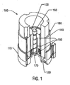
- FIG. 1 a pictorial representation of a rotating machine 100 in accordance with an embodiment of the present invention is provided.
- the illustrated embodiment shows a rotating machine 100 adapted for use in an electro-hydraulic power steering unit.
- the rotating machine 100 operates while immersed in hydraulic fluid.
- the hydraulic fluid lubricates and cools the components of the rotating machine during operation.
- the rotating machine 100 of the invention has applications to a variety of situations including other harsh environments. It is appreciated that other applications can be made in other situations in light of the description of the invention herein.
- the rotating machine 100 comprises four basic components: an endshield assembly 110 , a sensor assembly 120, a rotor assembly 130 , and a stator assembly 140.
- the sensor assembly 120 is located substantially within and is affixed to the endshield assembly 110 .
- the rotor assembly 130 includes a spiral-grooved shaft 160 which extends through an endshield protrusion 150 to form a hydro-dynamic bearing unit when the rotating machine 100 is operated while immersed in fluid (e.g. hydraulic fluid).
- the fluid acts as both a lubricant and a coolant.
- the rotor assembly 130 is axially secured in relation to the endshield 110 by a clip 170 positioned near one end of the shaft 160 beneath the endshield assembly 110.
- the stator assembly 140 surrounds the rotor assembly 130 and may be secured to the endshield 110 by a plurality of fasteners such as bolts 180.
- the endshield assembly 110 is shown in greater detail.
- the endshield assembly 110 is formed from cast aluminum. Other materials and methods of construction are contemplated depending on the specific motor environment.
- the endshield assembly 110 exhibits several stator bolt holes 200 for attaching the endshield assembly 110 to the stator assembly 140 via bolts 180 and several load bolt holes 210 for securing the endshield assembly 110 to a load (e.g. pump apparatus) attached to the rotating machine 100.
- Additional circulation holes 245 are also defined in the endshield assembly 110 to allow fluid to circulate into and out of the cavities formed by the endshield walls 220 and the endshield protrusion 150.
- the endshield walls 220 include recesses that are designed to receive the stator assembly 140. Formed within the endshield walls 220 is a stator assembly locating notch 230 that is used during assembly to orient the stator assembly 140 with respect to the endshield assembly 110 .
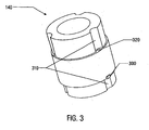
- FIG. 3 a simplified view of the stator assembly 140 is provided.
- Tab 300 extends from the stator assembly 140 and fits within the stator assembly locating notch 230 to ensure that the stator assembly 140 is in a known position with respect to the endshield 110 when the rotating machine 100 is assembled.
- the stator assembly 140 is constructed in conventional fashion such as from laminated stock.
- the stator assembly 140 defines bolt clearances 310 to allow bolts to be inserted through holes 320 and corresponding stator bolt holes 200 in the endshield 110 in order to fasten the stator assembly 140 to the endshield 110.
- FIG 4a provides a diagram of the stator assembly 140 and Figure 4b illustrates a circuit diagram of the phase windings.
- the stator assembly 140 includes a twelve slot, eight pole stator, having three phase windings 410, 420, 430 where each phase winding comprises four coils connected in parallel and where each coil is wound about a single stator tooth 400.
- the three phase windings 410, 420 , 430 are Wye connected.
- each coil consists of 13 turns of : I of AWG 14.5; or 2 of AWG 7.5; or 4 of AWG 20.5.
- two sensor assembly locating features are provided within the cavity formed by the walls 220 of the endshield 110. These features each comprise a rest 240 and two posts 250, 260 .
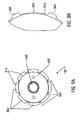
- the sensor assembly 120 is shown in Figure 5, and includes a locator body 540 having a pair of openings 500, 510 therein of a diameter substantially equal to the outer diameter of the two posts 250, 260.
- the sensor assembly 120 also includes a printed circuit board (PCB) array 520 with PCB lead wires 525 and three Hall effect devices 530.
- the locator body 540 is a molded plastic part that is formed such that it defines three pockets 545 which receive the three Hall effect devices 530 and positively locate the Hall effect devices 530 in the locator body 540. The center of each pocket is positioned at 30° from the adjacent pockets to control the frequency of the generated signals.
- the locator body 540 is preferably formed of glass-filled nylon or an engineering-approved equivalent material. In addition to positively positioning the Hall devices 530 , the plastic locator body 540 prevents the PCB leads 525 from contacting the rotor assembly 130.
- the PCB array 520 has openings 600 therein sized to accommodate leads which extend from the Hall effect devices 530.
- the PCB array 520 also has openings 610 therein for receiving the ends of the PCB lead wires 525.
- the PCB array 520 is received by an appropriately formed recess in the plastic locator 540 . This arrangement allows for selective soldering to be used to couple the leads from the Hall devices 530 and the PCB leads 525 to the PCB array 520.
- the sensor assembly 120 is assembled prior to its placement into the endshield assembly 110 of the rotating machine 100.
- the lead wires 525 are first mechanically connected to the PCB array 520 via openings 610 therein, as shown in Figure 6.
- the PCB array 520 is then snapped into engagement with the arms 542 on the underside of the locator body 540.
- the Hall effect devices 530 are then inserted into the pockets of the locator body 540 , such that movement of the Hall effect devices is restricted or prohibited and the lead wires 532 of the Hall effect devices extend through the openings 600 in the PCB array 520.
- the lead wires 525 are then electrically connected to the Hall effect leads 532 by application of a solder to the surface of the PCB array 520.
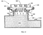
- selective soldering is preferably used to electrically connect the lead wires to the Hall effect leads. As shown in Figure 11, the selective soldering process is carried out by using a cookie-cutter like pattern 1300 sealed against the surface of the PCB array 520 to control the application of solder, thus preventing solder from coming into contact with other parts of the sensor assembly 120 such as the locator body 540.
- the cookie cutter pattern 1300 is placed above a solder bath 1310 , and the PCB array 520 is placed over the top of the cookie cutter pattern 1300 and sealed against the upper edge 1320 thereof.
- the solder bath 1310 is then pressurized 1320, causing a wave of solder to rise from the solder bath within the cookie cutter pattern 1300 and into contact with the surface of the PCB array 520 and the protruding ends of the lead wires 525 and Hall effect device leads 532 thereby electrically and mechanically connecting lead wires 525 to openings 610 and Hall effect leads 532 to openings 600.
- the PCB array 520 includes the required connections between the lead wires 525 and the Hall effect leads 532 .
- the sensor assembly 120 After the sensor assembly 120 has been assembled, it is positioned within the endshield 110 by placing the mounting holes 500, 510 of the plastic locator about the positioning posts 250 , 260 of the endshield 110 . The locator body is then secured to the positioning posts 250, 260. Preferably, the posts 250, 260 are deformed by spin riveting to secure the sensor assembly 120 to the endshield 110. Deformation of the posts is preferred since the number of parts used in the assembly is reduced, thereby alleviating concerns of parts coming loose in the rotating machine during operation. Alternatively, separate fasteners, such as locking washers or screws may be used to secure the locator body to the positioning posts. The manner in which the sensor assembly 120 is positioned within the endshield 110 is reflected Figure 7.
- a channel 270 is formed along the interior wall of the endshield 110 to allow the PCB leads 525 to exit the rotating machine 100 for connection to a controller.
- a slotted grommet 700 is inserted into the channel 270 and surrounds the lead wires in the channel.
- the grommet 700 may be formed of any material that meets chemical compatibility and temperature conditions for submersible use in an electro-hydraulic motor.
- the preferred material for the grommet 700 is glass filled nylon.
- the PCB leads 525 can be inserted into the grommet 700 through the slot therein, and the grommet 700 inserted into the channel 270 through the opening therein.
- This assembly obviates threading of the PCB leads through a hole in the endshield or other portion of the rotating machine, thus simplifying assembly of the rotating machine.
- the grommet 700 also inhibits chaffing of the PCB leads 525 and pinching of the wires 525 between the endshield 110 and the stator assembly 140 .
- the rotor assembly 130 includes a substantially cylindrical rotor member 800 having an outer surface 810 and an interior surface 820 .
- the rotor member 800 may be formed of a metallic material having good magnetic properties, such as powdered metal.
- a metallic material having good magnetic properties, such as powdered metal.
- One such preferred material is Z29 magnetic iron grade, 7.2 g/cc min. or an engineering approved equivalent.
- the rotor member 800 shown in Figure 8 comprises a solid metallic member, the rotor member may also comprise a laminated construction wherein a plurality of metallic discs are arranged in a stacked configuration and separated by alternating insulation discs.
- the interior surface 820 includes a stepped portion 830 at one end thereof, the inner surface of which frictionally engages the outer surface 840 of the rotor shaft 160.
- the shaft 160 has a first end 880 with a tapered or beveled edge. and a second end 890 which includes a tang 895 that may be configured to engage the shaft of a load (i.e. pump) to transmit the required torque and speed to the load.
- the shaft 160 is formed from heat treated metal, and preferably case hardened steel. that is hardened and ground to act as a suitable bearing journal.
- the shaft 160 is heat treated to provide a hard outer surface and a softer core.
- the shaft may be case hardened to about HRC 55 with a case depth of between about .50mm and .63mm, with a core hardness of between about HRC 30 and HRC 38.
- the hard outer surface of the shaft 160 forms a hydrodynamic bearing with the aluminum inner surface of the endshield protrusion 150.
- the interaction between the hard outer surface of the shaft 160 and the softer aluminum surface of the endshield protrusion 150 is necessary to prevent galling or surface destruction during use of the rotating machine 100, and particularly during start-up or shut-down of the machine.
- the softer core of the shaft 160 is useful in situations where the rotating machine 100 may be exposed to low temperature environments because the softer core is less brittle than the hard outer surface and therefore less prone to fracture.
- a spiral groove 850 is formed in the outer surface of the shaft 160. The spiral groove 850 acts to circulate fluid within the bearing assembly, making the shaft 160 an integral part of the bearing system.
- the outer surface 810 of the rotor member 800 includes a plurality of projecting ribs 900 that define a corresponding plurality of recesses 910 for receiving a corresponding plurality of magnets 860.
- the rotor member 800 includes eight ribs 900 defining eight recesses for receiving eight magnets 860 of alternating polarity. Any type of commercially available permanent magnet may be utilized, and preferably a neodymium magnet is used.
- the rotor magnets 860 act to transmit magnetic signals to the sensor assembly 120 , which in turn transmits electrical signals to a controller to control the speed of the rotating machine.
- the magnets 860 may be further secured in the recesses by application of a layer of adhesive material between the magnet and the outer surface 810 of the rotor member 800.
- the shear strength of the adhesive material holding the permanent magnet members 860 to the rotor member 800 depends, to a great extent, on the thickness of the layer of adhesive or glue between the magnets 860 and the outer surface 810 of the rotor member 800 .
- a secondary recess or "glue trough" 920 is formed within each main recess 910 defined by the outer surface 810 of the rotor member 800.
- the depth of the glue trough depends upon the type of adhesive used. According to one embodiment, the adhesive used is a single-part, heat cured epoxy, and the optimal depth of the glue trough is between about 0.05 mm and 0.15mm.
- the ribs 900 help properly position the permanent magnets 860 within the recesses 910 and also help resist the effects of torque on the magnets 860 in the event that the attachment means (e.g. glue) affixing the magnets 860 to the rotor member 800 fails.
- attachment means e.g. glue
- the magnets 860 are first secured in the recesses 910 .
- a layer of adhesive material is applied to the surface of the rotor member 800 in the main recess 910 , filling the glue trough 920 .
- the permanent magnets 860 are then placed within the main recesses 910, and the magnets 860 are compressed against the rotor member 800 .
- Some of the glue will collect in the glue trough 920, and the remainder will be extruded out of the main recess 910.
- the thickness of the glue layer between the permanent magnets 860 and the rotor member 800 will depend, to a great extent, on the depth of the glue trough 920.
- the rotor member and shaft 160 are assembled. preferably by inserting a beveled first end 880 of the shaft into the opening in an end of the rotor member.
- the shaft 160 may be coated with a light oil prior to press fitting into the rotor member 800 to ease the assembly. Care must be taken to ensure that the shaft outer surface and the inner surface of the stepped portion 830 of the rotor member 800 are free of burrs and foreign material, since the assembly is very susceptible to contamination after magnetization.
- an encapsulation layer or insert molding 870 may be provided surrounding the rotor member 800 with attached permanent magnets 860 , to serve as a further backup retention means should the adhesive fail.
- the encapsulating layer or insert molding 870 may serve as the primary magnet 860 retainer, where glue is not used to adhere the magnet 860 to the rotor member 800.
- the encapsulation layer 870 may be formed by placing the assembled rotor member 800 into a plastic injection tool and molding a plastic about the outer surfaces thereof.
- the encapsulation layer or insert molding 870 comprises glass-filled nylon.
- the size of the air gap between the stator assembly 140 and the magnets 860 of the rotor assembly 130 is important in determining the efficiency of the rotating machine 100 . At full load a smaller air gap results in a more efficient machine. At full load, the viscous drag between the rotor assembly 130 and the stator assembly 140 is not a major contributor to the load on the machine 100 . However, under no load or low load conditions, the viscous drag component is a major contributor to the load on the machine 100 . As the size of the air gap decreases, the viscous drag increases. In cases where the machine 100 is used intermittently, such as in a power steering pump application, the machine is frequently operated with little or no load. Therefore, it is important to balance the improved efficiency at full load with the increased viscous drag caused by the smaller air gap and its effect under no or low load conditions. In the illustrated embodiment, the air gap is between about 0.20 and 0.30 mm (0.008 and 0.012 inches).
- Figure 10 illustrates an alternate rotor member 800 embodiment which cooperates with the encapsulation layer 870 to mechanically secure the encapsulation layer to the rotor.
- the ribs 900 define longitudinal bores 1200 extending substantially the entire length of the ribs 900. Also, undercuts 1210, consisting of a notch in the rib 900 are defined in each rib.
- the encapsulation layer 870 is formed around the rotor member 800 after the magnets 860 have been attached, the encapsulation layer 870 substantially fills the undercuts 1210 and bores 1200, thus mechanically locking the encapsulation layer 870 to the rotor member 800.
- the shaft 160 of the rotor assembly 130 is positioned within the endshield protrusion 150 as shown in Figure 1.
- a clip 170 is then used to secure the shaft 160 against axial movement in relation to the endshield 110.
- a washer is placed between the clip 170 and the endshield 110 to form a thrust bearing as is known in the art.
- a washer may also be placed about the shaft 160 between the rotor member 800 and the free end of the endshield protrusion 150. No other endshield is required.
- no ball bearing assemblies are used in the rotating machine 100. Instead, the spiral-grooved shaft 160 and the endshield protrusion 150 form a hydro-dynamic unit bearing that utilizes the hydraulic fluid in which the motor 100 is submerged for lubrication and cooling.
- Thrust bearing surfaces are formed between the clip 170 and washer and the endshield 110 and also between the top of the endshield protrusion 150 and the overhanging surface 835 of the step portion 830 which is proximate the endshield protrusion 150 after assembly.
- the sensor assembly 120 orients the Hall devices 530 in the cavity defined between the interior surface 820 of the rotor member 800 and the outer surface of the rotor shaft 160, such that the sensing surface 550 of the Hall devices 530 is proximate the inner surface 865 of the portions of the magnets 860 that protrude beyond the end of the rotor member 800.
- the cooperation of the rotor tab 300, the endshield assembly locating notch 230 , the locating posts 250 , 260, and the sensor assembly mounting holes 500 , 510 ensure that the Hall devices 530 are oriented in a known position with respect to the stator assembly 140. Fixing the location of the Hall devices 530 with respect to the stator assembly 140 simplifies the assembly process.
- the output of the Hall effect devices 530 is used by a controller attached to the rotating machine 100 to control the timing of the phase winding switching. Due to the fixed orientations, the Hall devices 530 do not have to be adjusted to determine their positions relative to the stator assembly 140 for proper control of the rotating machine 100. The proper alignment is ensured during the manufacturing process due to the locating features.
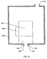
- the rotating machine 100 may be used in connection with a hydraulic power steering pump 1440 that is driven by the rotating machine 100 instead of a belt drive from the engine of a vehicle.
- the rotating machine 100 and pump 1440 are submerged in hydraulic fluid within a system housing 1400.
- the system housing 1400 includes a fluid inlet 1420 and a fluid outlet 1410 that corresponds to a fluid outlet 1450 of the pump 1440.
- the fluid outlet 1410 is sealed against the pump outlet 1450 by a seal 1430.
- the shaft 160 of the rotating machine 100 is connected to an impeller of the power steering pump 1440 and is fully submerged with the pump in power steering fluid.
- the unit bearing formed by the rotor assembly 130 and the endshield protrusion 150 relies upon the power steering fluid, rather than on ball bearings, to lubricate the shaft.
- the controller 1460 may also be located within the system housing 1400.
- rotation of the spiral-grooved shaft 160 draws hydraulic fluid through the holes 245 in the endshield 110 into the cavity defined between the outer surface 840 of the rotor shaft 160 and the endshield protrusion 150.
- the pressure and flow of hydraulic fluid between the outer surface 840 of the shaft 160 and the inner surface of the endshield protrusion 150 creates a lubricating layer between the endshield protrusion, the shaft and the rotor member 800.
- the motor drive has two endshields and uses ball bearings to lubricate the shaft.
- the motor is generally separated from the fluid by a seal on the shaft.
- the use of a ball bearing motor in the presence of hydraulic fluid limits the life expectancy of the ball bearings.
- the rotating machine 100 of the invention uses a single endshield and a unit bearing and is not susceptible to degradation from the power steering fluid as is the case with a ball bearing design.
- the unit bearing has improved reliability over ball bearing systems, in that it has improved resistance to shock and contamination, and thus has a longer expected life.
- the single endshield design also reduces the size and complexity of the completed assembly, simplifies the assembly of a magnetized rotor, and is ideally suited for automated assembly.
Landscapes
- Engineering & Computer Science (AREA)
- Power Engineering (AREA)
- Permanent Field Magnets Of Synchronous Machinery (AREA)
- Manufacture Of Motors, Generators (AREA)
- Iron Core Of Rotating Electric Machines (AREA)
- Motor Or Generator Frames (AREA)
- Connection Of Motors, Electrical Generators, Mechanical Devices, And The Like (AREA)
- Permanent Magnet Type Synchronous Machine (AREA)
Claims (4)
- Verfahren zum Zusammenbauen einer Rotorbaugruppe für eine Rotationsmaschine, wobei die Rotorbaugruppe einen Hauptrotorkörper (800) aufweist mit einer Aussenfläche (810), einer Vielzahl von Längsrippen (900), die aus der Aussenfläche (810) hervorstehen; einer Vielzahl von primären Aussparungen (910), welche durch benachbarte Rippen (900) begrenzt sind, und einer sekundären Aussparung (920) in der Aussenfläche (810) in mindestens einer der Vielzahl der primären Aussparungen (910), dadurch gekennzeichnet, dass das Verfahren folgende Schritte umfasst:Vorsehen einer Klebstofflage in mindestens einer primären Aussparung (910) und Füllen der sekundären Aussparung (920) mit Klebstoff;Einsetzen eines Magnets (860) in die primäre Aussparung (910); undAnpressen des Magnets (810) gegen den Hauptrotorkörper (800), um einen Teil des Klebstoffes aus der primären Aussparung (910) zu extrudieren und um eine Dicke der Klebstoffschicht zwischen dem Magnet (860) und dem Hauptrotorkörper (800) zu etablieren, die durch die Tiefe der sekundären Aussparung (920) bestimmt ist.
- Verfahren zum Zusammenbauen einer Rotorbaugruppe nach Anspruch 1, gekennzeichnet durch das Formen einer Verkapselungsschicht (870) um den Hauptrotorkörper (810) und den Magnet (860).
- Verfahren zum Zusammenbauen einer Rotorbaugruppe nach Anspruch 1, dadurch gekennzeichnet, dass der Hauptrotorkörper (800) eine Einschneidung (1210) in jeder Rippe (900) in dem Bereich des longitudinalen Mittelpunktes sowie eine longitudinale Bohrung (1200) durch jede Rippe (900) aufweist; und der Schritt des Formens der Verkapselungsschicht (870) um den Hauptrotorkörper (800) und den Magnet (860) das im Wesentlichen vollständiges Füllen mindestens einer der Einschneidungen (1210) und der longitudinalen Bohrungen (1200) mit dem Verkapselungsmaterial umfasst.
- Verfahren zum Zusammenbauen einer Rotorbaugruppe nach Anspruch 1, dadurch gekennzeichnet, dass die Sekundäraussparungen (920) mit einer Tiefe von zwischen 0,05 mm und 0,15 mm geformt werden und durch Verwenden eines wärmeaushärtbaren, Einkomponenten-Epoxydharzes als Klebstoff.
Applications Claiming Priority (3)
| Application Number | Priority Date | Filing Date | Title |
|---|---|---|---|
| US08/803,683 US6078121A (en) | 1997-02-21 | 1997-02-21 | Rotor assembly for a rotating machine |
| US803683 | 1997-02-21 | ||
| PCT/US1998/003119 WO1998037611A2 (en) | 1997-02-21 | 1998-02-19 | Rotor assembly for a rotating machine |
Publications (2)
| Publication Number | Publication Date |
|---|---|
| EP0962040A2 EP0962040A2 (de) | 1999-12-08 |
| EP0962040B1 true EP0962040B1 (de) | 2004-07-07 |
Family
ID=25187174
Family Applications (1)
| Application Number | Title | Priority Date | Filing Date |
|---|---|---|---|
| EP98906531A Expired - Lifetime EP0962040B1 (de) | 1997-02-21 | 1998-02-19 | Verfahren zur zusammenbau einer rotoranordnung fur rotierende machine |
Country Status (10)
| Country | Link |
|---|---|
| US (2) | US6078121A (de) |
| EP (1) | EP0962040B1 (de) |
| JP (1) | JP2000516440A (de) |
| KR (1) | KR100513098B1 (de) |
| CN (1) | CN1179463C (de) |
| AT (1) | ATE270794T1 (de) |
| AU (1) | AU6173298A (de) |
| DE (1) | DE69824953T2 (de) |
| ES (1) | ES2224361T3 (de) |
| WO (1) | WO1998037611A2 (de) |
Families Citing this family (56)
| Publication number | Priority date | Publication date | Assignee | Title |
|---|---|---|---|---|
| DE69913939T2 (de) * | 1998-01-23 | 2004-11-04 | Comair Rotron, Inc., San Ysidro | Motor mit niedriger bauhöhe |
| US6497035B1 (en) | 1999-12-06 | 2002-12-24 | Hr Textron, Inc. | Hall position sensor |
| KR100701871B1 (ko) * | 2000-11-10 | 2007-04-02 | 삼성광주전자 주식회사 | 선형압축기의 피스톤작동부 및 그 제조방법 |
| US7096566B2 (en) | 2001-01-09 | 2006-08-29 | Black & Decker Inc. | Method for making an encapsulated coil structure |
| BR0116740A (pt) | 2001-01-09 | 2003-12-23 | Black & Decker Inc | Motor elétrico tendo induzido revestido com um plástico termicamente condutivo |
| US20020089240A1 (en) | 2001-01-09 | 2002-07-11 | Du Hung T. | Electric motor having armature coated with a thermally conductive plastic |
| US7814641B2 (en) | 2001-01-09 | 2010-10-19 | Black & Decker Inc. | Method of forming a power tool |
| US6946758B2 (en) | 2001-01-09 | 2005-09-20 | Black & Decker Inc. | Dynamoelectric machine having encapsulated coil structure with one or more of phase change additives, insert molded features and insulated pinion |
| US6552459B2 (en) | 2001-03-20 | 2003-04-22 | Emerson Electric Co. | Permanent magnet rotor design |
| ZA200202936B (en) * | 2001-05-04 | 2002-11-22 | Inventio Ag | Permanent magnet electric machine. |
| US6661140B2 (en) | 2001-12-11 | 2003-12-09 | Black & Decker Inc. | Brushless motor having housing enabling alignment of stator and sensor |
| JP3783667B2 (ja) * | 2002-08-06 | 2006-06-07 | 三菱電機株式会社 | 回転電機およびその回転位置センサーの位置決め方法および位置決め装置 |
| JP4267309B2 (ja) * | 2002-12-03 | 2009-05-27 | 株式会社ジェイテクト | 接着構造体 |
| DE10393311T5 (de) * | 2003-02-27 | 2005-09-01 | Mitsubishi Denki K.K. | Magnetrotor für einen Motor |
| DE102004047991A1 (de) * | 2003-10-02 | 2005-06-23 | Aisan Kogyo K.K., Obu | Rotationswinkelsensoren |
| US6982532B2 (en) | 2003-12-08 | 2006-01-03 | A. O. Smith Corporation | Electric machine |
| CN1797904A (zh) * | 2004-12-20 | 2006-07-05 | 晋裕工业股份有限公司 | 凸形永磁转子马达 |
| US7183683B2 (en) * | 2005-06-23 | 2007-02-27 | Peopleflo Manufacturing Inc. | Inner magnet of a magnetic coupling |
| US7549205B2 (en) * | 2005-06-24 | 2009-06-23 | Peopleflo Manufacturing Inc. | Assembly and method for pre-stressing a magnetic coupling canister |
| US7352092B2 (en) * | 2005-08-22 | 2008-04-01 | Emerson Electric Co. | Integrated motor and controller assemblies for horizontal axis washing machines |
| US20070063603A1 (en) * | 2005-08-22 | 2007-03-22 | Levine Gregory M | Integrated motor and controller assemblies for horizontal axis washing machines |
| US20070071616A1 (en) * | 2005-09-27 | 2007-03-29 | Micropump, Inc., A Unit Of Idex Corporation | Segmented driven-magnet assemblies for pumps, and pumps comprising same |
| DE102005048546A1 (de) * | 2005-10-11 | 2007-04-12 | Robert Bosch Gmbh | Rotor für eine elektrische Maschine |
| DE602005021228D1 (de) * | 2005-11-18 | 2010-06-24 | Askoll Holding Srl | Verfahren zur Herstellung eines permanentmagnetischen Läufers für einen Synchronmotor insbesondere für eine Waschmaschinenpumpe für den Hausgebrauch und industrielle Anwendungen und ähnliches, und entsprechender Läufer |
| US20070138891A1 (en) * | 2005-12-19 | 2007-06-21 | Emerson Electric Co. | Magnet retention and positioning sleeve for surface mounted rotor assemblies |
| US20100013336A1 (en) * | 2006-10-13 | 2010-01-21 | Black & Decker Inc. | Anchoring System For A Stator Housing Assembly Having An Overmolding; Power Tool With Same |
| US7673380B2 (en) | 2007-04-23 | 2010-03-09 | Varco I/P, Inc. | Methods for making rotors for permanent magnet motors |
| US8598761B2 (en) * | 2007-05-03 | 2013-12-03 | In Motion Technologies Pty., Ltd. | Rotor magnet positioning device |
| KR100919403B1 (ko) * | 2007-05-17 | 2009-09-29 | 삼성전자주식회사 | 모터 |
| JP4707696B2 (ja) * | 2007-06-26 | 2011-06-22 | 本田技研工業株式会社 | アキシャルギャップ型モータ |
| US7626309B2 (en) * | 2007-09-12 | 2009-12-01 | Canopy Technologies, Llc | Method of balancing an embedded permanent magnet motor rotor |
| JP5493675B2 (ja) * | 2009-02-09 | 2014-05-14 | 株式会社ジェイテクト | 電動モータおよびロータ |
| CN102013780B (zh) * | 2009-09-07 | 2014-03-12 | 德昌电机(深圳)有限公司 | 微型无刷电机 |
| CN102035330B (zh) * | 2009-10-07 | 2014-09-24 | 阿斯莫有限公司 | 电动机 |
| KR101134970B1 (ko) * | 2009-11-19 | 2012-04-09 | 현대자동차주식회사 | 전기식 워터 펌프 |
| KR101134969B1 (ko) | 2009-11-19 | 2012-04-09 | 현대자동차주식회사 | 전기식 워터 펌프의 고정자 제작 방법 |
| KR101134968B1 (ko) * | 2009-11-19 | 2012-04-09 | 현대자동차주식회사 | 전기식 워터 펌프 |
| KR101072328B1 (ko) * | 2009-11-19 | 2011-10-11 | 현대자동차주식회사 | 전기식 워터 펌프 |
| JP2012100380A (ja) * | 2010-10-29 | 2012-05-24 | Nippon Steel Corp | 内転形電動機用固定子 |
| US9190878B2 (en) | 2012-03-16 | 2015-11-17 | Globe Motors, Inc. | Rotor including anti-rotation feature for multi-pole structure |
| EP2639935B1 (de) * | 2012-03-16 | 2014-11-26 | Siemens Aktiengesellschaft | Rotor mit Permanenterregung, elektrische Maschine mit einem solchen Rotor und Herstellungsverfahren für den Rotor |
| US9190888B2 (en) | 2012-04-13 | 2015-11-17 | Globe Motors, Inc. | Method of positioning a sensor within a motor assembly |
| DE102012221422A1 (de) * | 2012-11-23 | 2014-05-28 | Continental Automotive Gmbh | Rotor eines Elektromotors und Verfahren zur Herstellung des Rotors |
| US9431881B2 (en) | 2013-03-15 | 2016-08-30 | Regal Beloit America, Inc. | Electric machine housing |
| TWI493837B (zh) * | 2013-06-07 | 2015-07-21 | Durq Machinery Corp | Brushless permanent magnet motor |
| TWI487247B (zh) * | 2013-06-07 | 2015-06-01 | Durq Machinery Corp | Brushless permanent magnet motor |
| KR101591048B1 (ko) | 2014-01-23 | 2016-02-02 | 엘지이노텍 주식회사 | 모터용 로터와 이를 포함하는 모터 및 로터의 제조방법 |
| US10177637B2 (en) * | 2014-02-17 | 2019-01-08 | Mitsubishi Electric Corporation | Permanent magnet motor |
| US10742082B2 (en) * | 2014-12-31 | 2020-08-11 | Ingersoll-Rand Industrial U.S., Inc. | Fixation system for a permanent magnet rotor |
| US10811945B2 (en) * | 2017-08-25 | 2020-10-20 | Schaeffler Technologies AG & Co. KG | Permanent magnet machine including ferromagnetic components for external field weakening and method of constructing |
| US10481269B2 (en) | 2017-12-07 | 2019-11-19 | Ouster, Inc. | Rotating compact light ranging system |
| WO2020012420A2 (de) * | 2018-07-13 | 2020-01-16 | Nidec Corporation | Spritzgegossener magnethalter für einen bürstenlosen elektromotor |
| DE102018116987A1 (de) * | 2018-07-13 | 2020-01-16 | Nidec Corporation | Rotoreinheit für einen bürstenlosen Elektromotor mit einstückigen Magnetflussleitern |
| DE102019206333B4 (de) | 2019-05-03 | 2023-03-02 | Hawe Hydraulik Se | Hydraulikaggregat |
| FR3149086B1 (fr) * | 2023-05-22 | 2025-07-18 | Valeo Embrayages | Ensemble comprenant un arbre et un aimant |
| JP7672544B1 (ja) * | 2024-05-14 | 2025-05-07 | 三菱電機ビルソリューションズ株式会社 | 回転電機のローター |
Family Cites Families (70)
| Publication number | Priority date | Publication date | Assignee | Title |
|---|---|---|---|---|
| FR2278128A1 (fr) * | 1974-07-08 | 1976-02-06 | Lencot Gerard | Plateau d'entrainement de machine phonographique sur paliers aerostatiques |
| NL7601060A (nl) * | 1976-02-03 | 1977-08-05 | Philips Nv | Werkwijze voor het vervaardigen van een uit kunst- stof bestaand rotatie-symmetrisch lager. |
| JPS55115315A (en) * | 1979-02-28 | 1980-09-05 | Sayama Dengiyou Kk | Manufacturing method of small-sized transformer |
| US4645960A (en) * | 1979-07-30 | 1987-02-24 | Litton Systems, Inc. | Ferro-fluid bearing |
| US4535373A (en) * | 1980-12-29 | 1985-08-13 | Papst-Motoren Gmbh & Co. Kg | Labyrinth seal in disk storage drive |
| IT8018706A0 (it) * | 1980-04-14 | 1980-04-14 | Bonaccorso Francesco | Cuscinetto portante a sostentamento fluido-statico e fluido-dinamico costruibile in serie |
| CH654455A5 (de) * | 1980-05-10 | 1986-02-14 | Papst Motoren Gmbh & Co Kg | Buerstenlose gleichstrommotoranordnung, insbesondere fuer magnetplattenantriebe. |
| JPS585518A (ja) | 1981-07-01 | 1983-01-12 | Nippon Seiko Kk | 動圧形スピンドル装置 |
| US4599664A (en) * | 1982-03-01 | 1986-07-08 | Papst-Motoren Gmbh & Co Kg | Disk storage drive |
| US4553183A (en) | 1982-06-28 | 1985-11-12 | Atasi Corporation | Memory storage apparatus having improved housing and base plate arrangement |
| JPS5928757A (ja) * | 1982-08-11 | 1984-02-15 | Takahashi Yoshiteru | 回転多面鏡走査装置 |
| US4499661A (en) | 1982-09-09 | 1985-02-19 | Emerson Electric Co. | Method of fabricating die cast rotor with one piece oil return/rotor shaft securement member |
| US4547713A (en) * | 1982-11-05 | 1985-10-15 | Kollmorgen Technologies Corporation | Toroidally wound brushless DC motor |
| DE3248186C2 (de) * | 1982-12-27 | 1986-10-23 | SCHUNK Industrieverwaltung GmbH, 6301 Heuchelheim | Verfahren zur Herstellung einer Gleitlagerbuchse |
| JPS604617A (ja) * | 1983-06-24 | 1985-01-11 | Canon Inc | 動圧流体軸受 |
| JPS6026676U (ja) * | 1983-07-28 | 1985-02-22 | 日本精工株式会社 | 磁気ディスク記憶装置 |
| US4533183A (en) * | 1983-09-19 | 1985-08-06 | The United States Of America As Represented By The Secretary Of The Army | Military wheel-tire assembly |
| US4515486A (en) * | 1984-02-03 | 1985-05-07 | Ide Russell D | Elastomeric supported hydrodynamic bearing |
| US4635352A (en) | 1984-02-29 | 1987-01-13 | General Electric Company | Method of assembling a rotor assembly |
| US4607181A (en) | 1984-12-06 | 1986-08-19 | Hayward Tyler Inc. | High temperature submersible electric motor |
| EP0206516A3 (de) * | 1985-05-21 | 1988-08-10 | Ferrofluidics Corporation | Magnetische Flüssigkeit, Methode ihrer Herstellung und Apparat und Methode zu ihrer Anwendung |
| JPS61271168A (ja) * | 1985-05-27 | 1986-12-01 | Honda Motor Co Ltd | 電動式パワ−ステアリング装置の電動機駆動回路 |
| US4625392A (en) * | 1985-09-05 | 1986-12-02 | General Electric Company | Method of manufacturing a molded rotatable assembly for dynamoelectric machines |
| EP0229911B1 (de) * | 1985-11-28 | 1990-09-19 | Ebara Corporation | Elektrisch angetriebenes Gerät |
| JPH0691717B2 (ja) * | 1986-09-26 | 1994-11-14 | 株式会社荏原製作所 | 電動機械 |
| DE3600721A1 (de) * | 1986-01-13 | 1987-07-16 | Balcke Duerr Ag | Lageranordnung |
| US4689511A (en) | 1986-03-31 | 1987-08-25 | Emerson Electric Co. | Drain assembly for an electric motor |
| JPS6320266A (ja) * | 1986-07-11 | 1988-01-27 | Mitsubishi Electric Corp | モ−タ駆動式パワ−ステアリング制御装置 |
| JPS63100416A (ja) * | 1986-10-17 | 1988-05-02 | Ricoh Co Ltd | 光偏向装置 |
| US4841183A (en) | 1986-10-27 | 1989-06-20 | Emerson Electric Co. | Dynamoelectric machine construction and method |
| US4712031A (en) | 1986-11-12 | 1987-12-08 | Ancor Industries, Inc. | Unit bearing motor with hydrodynamic lubricating system |
| JPS63241515A (ja) * | 1987-03-30 | 1988-10-06 | Ebara Corp | ポリゴンミラ− |
| JPS63241517A (ja) * | 1987-03-30 | 1988-10-06 | Ebara Corp | ポリゴンミラ− |
| JPS63241516A (ja) * | 1987-03-30 | 1988-10-06 | Ebara Corp | ポリゴンミラ− |
| JPH0284032A (ja) * | 1988-04-25 | 1990-03-26 | Matsushita Electric Works Ltd | 永久磁石回転子 |
| GB2217924B (en) * | 1988-04-25 | 1992-10-07 | Matsushita Electric Works Ltd | Permanent magnet rotor |
| US5040286A (en) * | 1988-06-08 | 1991-08-20 | General Electric Company | Method for making permanent magnet rotor |
| US4862026A (en) | 1988-06-20 | 1989-08-29 | Richard Riback | Motor unit bearing |
| US4894496A (en) | 1988-06-29 | 1990-01-16 | Palumbo Nicholas R | Auxiliary winding cut-out switch for sump pump motor |
| US4973872A (en) * | 1988-10-07 | 1990-11-27 | Emerson Electric Co. | Dynamoelectric machine rotor assembly with improved magnet retention stucture |
| US4910861A (en) * | 1988-10-07 | 1990-03-27 | Emerson Electric Co. | Method of manufacturing retention structure for electric motor rotor magnets |
| JP2669549B2 (ja) * | 1988-12-14 | 1997-10-29 | 株式会社日立製作所 | 磁気デイスク装置 |
| US4998033A (en) * | 1989-04-12 | 1991-03-05 | Ebara Corporation | Gas dynamic bearing for spindle motor |
| ATE95349T1 (de) * | 1989-07-24 | 1993-10-15 | Ebara Corp | Spindelmotor. |
| US4961018A (en) | 1989-08-11 | 1990-10-02 | Wayne/Scott Fetzer Company | Enclosed pump motor and wiring thereof |
| JP2870057B2 (ja) * | 1989-11-07 | 1999-03-10 | 日本精工株式会社 | 動圧軸受装置 |
| US5076762A (en) | 1990-02-07 | 1991-12-31 | A. O. Smith Corporation | Vertical sump pump motor |
| JPH03256546A (ja) * | 1990-03-05 | 1991-11-15 | Ebara Corp | スピンドルモータ |
| US5158440A (en) * | 1990-10-04 | 1992-10-27 | Ingersoll-Rand Company | Integrated centrifugal pump and motor |
| JPH04306170A (ja) * | 1991-04-02 | 1992-10-28 | Koyo Seiko Co Ltd | 電動パワーステアリング装置 |
| GB2258566B (en) * | 1991-08-07 | 1994-12-21 | Johnson Electric Sa | Permanent magnet rotor |
| JPH0585518A (ja) * | 1991-09-27 | 1993-04-06 | Nippon Tansan Kk | 包装機への板状体の送り込み装置 |
| US5397951A (en) * | 1991-11-29 | 1995-03-14 | Fanuc Ltd. | Rotor for a synchronous rotary machine |
| ES2080968T3 (es) * | 1992-01-17 | 1996-02-16 | Siemens Ag | Bomba de rotor humedo. |
| US6348752B1 (en) * | 1992-04-06 | 2002-02-19 | General Electric Company | Integral motor and control |
| US5257828A (en) * | 1992-06-03 | 1993-11-02 | Trw Inc. | Method and apparatus for controlling damping in an electric assist steering system for vehicle yaw rate control |
| DE4235962C2 (de) * | 1992-10-24 | 1997-11-27 | Temic Auto Electr Motors Gmbh | Elektromotor, insbesondere feuchtigkeitsdicht geschlossener Kommutatormotor mit einem axial angeflanschten Antriebsgehäuse |
| JPH06173944A (ja) * | 1992-12-03 | 1994-06-21 | Ebara Corp | 気体動圧軸受 |
| JPH06239249A (ja) * | 1993-02-18 | 1994-08-30 | Koyo Seiko Co Ltd | 電動パワーステアリング装置 |
| US5281881A (en) * | 1993-02-25 | 1994-01-25 | General Motors Corporation | Frame and magnet assembly for a dynamoelectric machine |
| US5443413A (en) * | 1993-07-30 | 1995-08-22 | Western Atlas Inc. | Brushless spindle motor for a grinding machine including hydrostatic bearings |
| DE4335390B4 (de) * | 1993-10-16 | 2007-04-12 | Trw Fahrwerksysteme Gmbh & Co Kg | Servolenkvorrichtung |
| US5473231A (en) * | 1994-05-11 | 1995-12-05 | Trw Inc. | Method and apparatus for controlling an electric assist steering system using an adaptive torque filter |
| JPH0819290A (ja) * | 1994-06-30 | 1996-01-19 | Mitsubishi Electric Corp | パワーステアリング用電動機の制御装置 |
| JP3525195B2 (ja) * | 1994-08-02 | 2004-05-10 | 光洋精工株式会社 | 電動パワーステアリング装置 |
| US5517415A (en) * | 1994-10-26 | 1996-05-14 | Trw Inc. | Method and apparatus for detecting a motor stall condition in an electric assist steering system |
| US5475289A (en) * | 1994-11-04 | 1995-12-12 | Trw Inc. | Method and apparatus for controlling an electric assist steering system using two-dimensional interpolation for current commands |
| US5758709A (en) * | 1995-12-04 | 1998-06-02 | General Electric Company | Method of fabricating a rotor for an electric motor |
| BR9601756A (pt) * | 1996-05-29 | 1998-09-29 | Brasil Compressores Sa | Capa para rotor de motor elétrico |
| US5831364A (en) * | 1997-01-22 | 1998-11-03 | Ingersoll-Dresser Pump Company | Encapsulated magnet carrier |
-
1997
- 1997-02-21 US US08/803,683 patent/US6078121A/en not_active Expired - Lifetime
-
1998
- 1998-02-19 CN CNB988033860A patent/CN1179463C/zh not_active Expired - Fee Related
- 1998-02-19 ES ES98906531T patent/ES2224361T3/es not_active Expired - Lifetime
- 1998-02-19 WO PCT/US1998/003119 patent/WO1998037611A2/en not_active Ceased
- 1998-02-19 EP EP98906531A patent/EP0962040B1/de not_active Expired - Lifetime
- 1998-02-19 AU AU61732/98A patent/AU6173298A/en not_active Abandoned
- 1998-02-19 KR KR10-1999-7007496A patent/KR100513098B1/ko not_active Expired - Fee Related
- 1998-02-19 JP JP10536824A patent/JP2000516440A/ja active Pending
- 1998-02-19 AT AT98906531T patent/ATE270794T1/de not_active IP Right Cessation
- 1998-02-19 DE DE69824953T patent/DE69824953T2/de not_active Expired - Fee Related
-
1999
- 1999-07-21 US US09/358,311 patent/US6324745B1/en not_active Expired - Lifetime
Also Published As
| Publication number | Publication date |
|---|---|
| US6324745B1 (en) | 2001-12-04 |
| EP0962040A2 (de) | 1999-12-08 |
| KR20000071206A (ko) | 2000-11-25 |
| DE69824953T2 (de) | 2005-08-25 |
| DE69824953D1 (de) | 2004-08-12 |
| ES2224361T3 (es) | 2005-03-01 |
| US6078121A (en) | 2000-06-20 |
| CN1179463C (zh) | 2004-12-08 |
| ATE270794T1 (de) | 2004-07-15 |
| WO1998037611A3 (en) | 1998-11-19 |
| WO1998037611A2 (en) | 1998-08-27 |
| KR100513098B1 (ko) | 2005-09-07 |
| JP2000516440A (ja) | 2000-12-05 |
| CN1250554A (zh) | 2000-04-12 |
| AU6173298A (en) | 1998-09-09 |
Similar Documents
| Publication | Publication Date | Title |
|---|---|---|
| EP0962040B1 (de) | Verfahren zur zusammenbau einer rotoranordnung fur rotierende machine | |
| US6025665A (en) | Rotating machine for use in a pressurized fluid system | |
| US7011449B2 (en) | Bearing unit and motor using same | |
| EP2379892B1 (de) | Vollständig untertauchbare integrierte elektroölpumpe | |
| US7986068B2 (en) | Motor | |
| KR101127196B1 (ko) | 액셜 갭형 전동기 | |
| CN107786017B (zh) | 旋转电机的转子结构 | |
| US7029179B2 (en) | Bearing unit, and motor using same | |
| JP2004236390A (ja) | 小型ブラシレスモータ | |
| JP2012508344A6 (ja) | 完全サブマージド一体形電気オイルポンプ | |
| US20070120433A1 (en) | Bearing Unit and Electric Motor Furnished Therewith | |
| CN114583897A (zh) | 组件、具有该组件的致动器及用于固定传感器元件的方法 | |
| US7723877B2 (en) | Motor | |
| WO2009126853A2 (en) | Rotor assembly including sintered magnet core assembly | |
| US4841183A (en) | Dynamoelectric machine construction and method | |
| CN208445399U (zh) | 马达 | |
| US11277050B2 (en) | Electric motor | |
| JP2002152999A (ja) | 電動機 | |
| EP4568075A1 (de) | Verbindungsstruktur für eine jochlose und segmentierte ankeraxialflussmaschine | |
| JPH11225456A (ja) | モータ | |
| JPH1175356A (ja) | ディスクの回転駆動装置のロータ装置 | |
| KR20000044110A (ko) | 스핀들 모터 | |
| JPH11275799A (ja) | モータ |
Legal Events
| Date | Code | Title | Description |
|---|---|---|---|
| PUAI | Public reference made under article 153(3) epc to a published international application that has entered the european phase |
Free format text: ORIGINAL CODE: 0009012 |
|
| 17P | Request for examination filed |
Effective date: 19990818 |
|
| AK | Designated contracting states |
Kind code of ref document: A2 Designated state(s): AT BE CH DE DK ES FI FR GB GR IE IT LI LU MC NL PT SE |
|
| AX | Request for extension of the european patent |
Free format text: AL PAYMENT 19990818;LT PAYMENT 19990818;LV PAYMENT 19990818;MK PAYMENT 19990818;RO PAYMENT 19990818;SI PAYMENT 19990818 |
|
| 17Q | First examination report despatched |
Effective date: 20001116 |
|
| GRAP | Despatch of communication of intention to grant a patent |
Free format text: ORIGINAL CODE: EPIDOSNIGR1 |
|
| RTI1 | Title (correction) |
Free format text: METHOD OF ASSEMBLING A ROTOR ASSEMBLY FOR A ROTATING MACHINE |
|
| GRAS | Grant fee paid |
Free format text: ORIGINAL CODE: EPIDOSNIGR3 |
|
| GRAA | (expected) grant |
Free format text: ORIGINAL CODE: 0009210 |
|
| AK | Designated contracting states |
Kind code of ref document: B1 Designated state(s): AT BE CH DE DK ES FI FR GB GR IE IT LI LU MC NL PT SE |
|
| AX | Request for extension of the european patent |
Extension state: AL LT LV MK RO SI |
|
| PG25 | Lapsed in a contracting state [announced via postgrant information from national office to epo] |
Ref country code: NL Free format text: LAPSE BECAUSE OF FAILURE TO SUBMIT A TRANSLATION OF THE DESCRIPTION OR TO PAY THE FEE WITHIN THE PRESCRIBED TIME-LIMIT Effective date: 20040707 Ref country code: LI Free format text: LAPSE BECAUSE OF FAILURE TO SUBMIT A TRANSLATION OF THE DESCRIPTION OR TO PAY THE FEE WITHIN THE PRESCRIBED TIME-LIMIT Effective date: 20040707 Ref country code: FI Free format text: LAPSE BECAUSE OF FAILURE TO SUBMIT A TRANSLATION OF THE DESCRIPTION OR TO PAY THE FEE WITHIN THE PRESCRIBED TIME-LIMIT Effective date: 20040707 Ref country code: CH Free format text: LAPSE BECAUSE OF FAILURE TO SUBMIT A TRANSLATION OF THE DESCRIPTION OR TO PAY THE FEE WITHIN THE PRESCRIBED TIME-LIMIT Effective date: 20040707 Ref country code: BE Free format text: LAPSE BECAUSE OF FAILURE TO SUBMIT A TRANSLATION OF THE DESCRIPTION OR TO PAY THE FEE WITHIN THE PRESCRIBED TIME-LIMIT Effective date: 20040707 Ref country code: AT Free format text: LAPSE BECAUSE OF FAILURE TO SUBMIT A TRANSLATION OF THE DESCRIPTION OR TO PAY THE FEE WITHIN THE PRESCRIBED TIME-LIMIT Effective date: 20040707 |
|
| REG | Reference to a national code |
Ref country code: GB Ref legal event code: FG4D |
|
| REG | Reference to a national code |
Ref country code: CH Ref legal event code: EP |
|
| REG | Reference to a national code |
Ref country code: IE Ref legal event code: FG4D |
|
| REF | Corresponds to: |
Ref document number: 69824953 Country of ref document: DE Date of ref document: 20040812 Kind code of ref document: P |
|
| PG25 | Lapsed in a contracting state [announced via postgrant information from national office to epo] |
Ref country code: SE Free format text: LAPSE BECAUSE OF FAILURE TO SUBMIT A TRANSLATION OF THE DESCRIPTION OR TO PAY THE FEE WITHIN THE PRESCRIBED TIME-LIMIT Effective date: 20041007 Ref country code: GR Free format text: LAPSE BECAUSE OF FAILURE TO SUBMIT A TRANSLATION OF THE DESCRIPTION OR TO PAY THE FEE WITHIN THE PRESCRIBED TIME-LIMIT Effective date: 20041007 Ref country code: DK Free format text: LAPSE BECAUSE OF FAILURE TO SUBMIT A TRANSLATION OF THE DESCRIPTION OR TO PAY THE FEE WITHIN THE PRESCRIBED TIME-LIMIT Effective date: 20041007 |
|
| LTIE | Lt: invalidation of european patent or patent extension |
Effective date: 20040707 |
|
| NLV1 | Nl: lapsed or annulled due to failure to fulfill the requirements of art. 29p and 29m of the patents act | ||
| REG | Reference to a national code |
Ref country code: CH Ref legal event code: PL |
|
| ET | Fr: translation filed | ||
| PGFP | Annual fee paid to national office [announced via postgrant information from national office to epo] |
Ref country code: GB Payment date: 20050216 Year of fee payment: 8 |
|
| PGFP | Annual fee paid to national office [announced via postgrant information from national office to epo] |
Ref country code: FR Payment date: 20050217 Year of fee payment: 8 |
|
| PG25 | Lapsed in a contracting state [announced via postgrant information from national office to epo] |
Ref country code: LU Free format text: LAPSE BECAUSE OF NON-PAYMENT OF DUE FEES Effective date: 20050219 |
|
| PG25 | Lapsed in a contracting state [announced via postgrant information from national office to epo] |
Ref country code: IE Free format text: LAPSE BECAUSE OF NON-PAYMENT OF DUE FEES Effective date: 20050221 |
|
| PG25 | Lapsed in a contracting state [announced via postgrant information from national office to epo] |
Ref country code: MC Free format text: LAPSE BECAUSE OF NON-PAYMENT OF DUE FEES Effective date: 20050228 |
|
| REG | Reference to a national code |
Ref country code: ES Ref legal event code: FG2A Ref document number: 2224361 Country of ref document: ES Kind code of ref document: T3 |
|
| PGFP | Annual fee paid to national office [announced via postgrant information from national office to epo] |
Ref country code: ES Payment date: 20050309 Year of fee payment: 8 |
|
| PGFP | Annual fee paid to national office [announced via postgrant information from national office to epo] |
Ref country code: DE Payment date: 20050331 Year of fee payment: 8 |
|
| PLBE | No opposition filed within time limit |
Free format text: ORIGINAL CODE: 0009261 |
|
| STAA | Information on the status of an ep patent application or granted ep patent |
Free format text: STATUS: NO OPPOSITION FILED WITHIN TIME LIMIT |
|
| 26N | No opposition filed |
Effective date: 20050408 |
|
| REG | Reference to a national code |
Ref country code: IE Ref legal event code: MM4A |
|
| PG25 | Lapsed in a contracting state [announced via postgrant information from national office to epo] |
Ref country code: GB Free format text: LAPSE BECAUSE OF NON-PAYMENT OF DUE FEES Effective date: 20060219 |
|
| PG25 | Lapsed in a contracting state [announced via postgrant information from national office to epo] |
Ref country code: ES Free format text: LAPSE BECAUSE OF NON-PAYMENT OF DUE FEES Effective date: 20060220 |
|
| PGFP | Annual fee paid to national office [announced via postgrant information from national office to epo] |
Ref country code: IT Payment date: 20060228 Year of fee payment: 9 |
|
| PG25 | Lapsed in a contracting state [announced via postgrant information from national office to epo] |
Ref country code: DE Free format text: LAPSE BECAUSE OF NON-PAYMENT OF DUE FEES Effective date: 20060901 |
|
| GBPC | Gb: european patent ceased through non-payment of renewal fee |
Effective date: 20060219 |
|
| REG | Reference to a national code |
Ref country code: FR Ref legal event code: ST Effective date: 20061031 |
|
| REG | Reference to a national code |
Ref country code: ES Ref legal event code: FD2A Effective date: 20060220 |
|
| PG25 | Lapsed in a contracting state [announced via postgrant information from national office to epo] |
Ref country code: PT Free format text: LAPSE BECAUSE OF NON-PAYMENT OF DUE FEES Effective date: 20041207 |
|
| PG25 | Lapsed in a contracting state [announced via postgrant information from national office to epo] |
Ref country code: FR Free format text: LAPSE BECAUSE OF NON-PAYMENT OF DUE FEES Effective date: 20060228 |
|
| PG25 | Lapsed in a contracting state [announced via postgrant information from national office to epo] |
Ref country code: IT Free format text: LAPSE BECAUSE OF NON-PAYMENT OF DUE FEES Effective date: 20070219 |