EP0958100B1 - Method of inserting a fastener element, bolt element, riveting die and component assembly - Google Patents
Method of inserting a fastener element, bolt element, riveting die and component assembly Download PDFInfo
- Publication number
- EP0958100B1 EP0958100B1 EP96933386A EP96933386A EP0958100B1 EP 0958100 B1 EP0958100 B1 EP 0958100B1 EP 96933386 A EP96933386 A EP 96933386A EP 96933386 A EP96933386 A EP 96933386A EP 0958100 B1 EP0958100 B1 EP 0958100B1
- Authority
- EP
- European Patent Office
- Prior art keywords
- sheet metal
- metal component
- shaft portion
- collar
- head portion
- Prior art date
- Legal status (The legal status is an assumption and is not a legal conclusion. Google has not performed a legal analysis and makes no representation as to the accuracy of the status listed.)
- Expired - Lifetime
Links
- 238000000034 method Methods 0.000 title claims abstract description 43
- 239000002184 metal Substances 0.000 claims abstract description 190
- 229910052751 metal Inorganic materials 0.000 claims abstract description 190
- 230000009471 action Effects 0.000 claims abstract description 8
- 239000000463 material Substances 0.000 claims description 39
- 230000015572 biosynthetic process Effects 0.000 claims description 8
- 238000005304 joining Methods 0.000 claims description 7
- 238000003825 pressing Methods 0.000 claims description 5
- 230000007704 transition Effects 0.000 claims description 5
- 238000005520 cutting process Methods 0.000 claims description 4
- 230000010339 dilation Effects 0.000 claims description 3
- 230000035515 penetration Effects 0.000 claims description 2
- 238000004080 punching Methods 0.000 abstract description 6
- 210000003128 head Anatomy 0.000 description 35
- 238000003780 insertion Methods 0.000 description 19
- 230000037431 insertion Effects 0.000 description 19
- 238000013461 design Methods 0.000 description 12
- 230000002349 favourable effect Effects 0.000 description 9
- 210000001331 nose Anatomy 0.000 description 9
- 239000007769 metal material Substances 0.000 description 8
- 238000004519 manufacturing process Methods 0.000 description 7
- 230000002093 peripheral effect Effects 0.000 description 7
- 230000008901 benefit Effects 0.000 description 6
- XEEYBQQBJWHFJM-UHFFFAOYSA-N Iron Chemical compound [Fe] XEEYBQQBJWHFJM-UHFFFAOYSA-N 0.000 description 4
- 238000012966 insertion method Methods 0.000 description 4
- 238000005096 rolling process Methods 0.000 description 4
- 238000007493 shaping process Methods 0.000 description 4
- 238000005260 corrosion Methods 0.000 description 3
- 230000007797 corrosion Effects 0.000 description 3
- 238000009434 installation Methods 0.000 description 3
- 230000008569 process Effects 0.000 description 3
- 229910000838 Al alloy Inorganic materials 0.000 description 2
- 239000004411 aluminium Substances 0.000 description 2
- 229910052782 aluminium Inorganic materials 0.000 description 2
- XAGFODPZIPBFFR-UHFFFAOYSA-N aluminium Chemical compound [Al] XAGFODPZIPBFFR-UHFFFAOYSA-N 0.000 description 2
- 230000006835 compression Effects 0.000 description 2
- 238000007906 compression Methods 0.000 description 2
- 238000010276 construction Methods 0.000 description 2
- 230000000994 depressogenic effect Effects 0.000 description 2
- 238000005553 drilling Methods 0.000 description 2
- 229910052742 iron Inorganic materials 0.000 description 2
- 230000009467 reduction Effects 0.000 description 2
- 229910000975 Carbon steel Inorganic materials 0.000 description 1
- 229910000954 Medium-carbon steel Inorganic materials 0.000 description 1
- 229910000831 Steel Inorganic materials 0.000 description 1
- 229910045601 alloy Inorganic materials 0.000 description 1
- 239000000956 alloy Substances 0.000 description 1
- 230000000712 assembly Effects 0.000 description 1
- 238000000429 assembly Methods 0.000 description 1
- 230000004323 axial length Effects 0.000 description 1
- 230000009286 beneficial effect Effects 0.000 description 1
- 239000010962 carbon steel Substances 0.000 description 1
- 238000011109 contamination Methods 0.000 description 1
- 238000012937 correction Methods 0.000 description 1
- 238000011161 development Methods 0.000 description 1
- 230000018109 developmental process Effects 0.000 description 1
- 238000010586 diagram Methods 0.000 description 1
- 230000000694 effects Effects 0.000 description 1
- 210000000887 face Anatomy 0.000 description 1
- 230000005484 gravity Effects 0.000 description 1
- 238000010438 heat treatment Methods 0.000 description 1
- 238000011900 installation process Methods 0.000 description 1
- 150000002739 metals Chemical class 0.000 description 1
- 239000000203 mixture Substances 0.000 description 1
- 239000003973 paint Substances 0.000 description 1
- 230000037361 pathway Effects 0.000 description 1
- 238000005381 potential energy Methods 0.000 description 1
- 238000012545 processing Methods 0.000 description 1
- 238000010079 rubber tapping Methods 0.000 description 1
- 238000003892 spreading Methods 0.000 description 1
- 230000007480 spreading Effects 0.000 description 1
- 239000010959 steel Substances 0.000 description 1
- 238000003860 storage Methods 0.000 description 1
- 238000004381 surface treatment Methods 0.000 description 1
- 239000011800 void material Substances 0.000 description 1
- 238000005406 washing Methods 0.000 description 1
Images


Classifications
-
- F—MECHANICAL ENGINEERING; LIGHTING; HEATING; WEAPONS; BLASTING
- F16—ENGINEERING ELEMENTS AND UNITS; GENERAL MEASURES FOR PRODUCING AND MAINTAINING EFFECTIVE FUNCTIONING OF MACHINES OR INSTALLATIONS; THERMAL INSULATION IN GENERAL
- F16B—DEVICES FOR FASTENING OR SECURING CONSTRUCTIONAL ELEMENTS OR MACHINE PARTS TOGETHER, e.g. NAILS, BOLTS, CIRCLIPS, CLAMPS, CLIPS OR WEDGES; JOINTS OR JOINTING
- F16B37/00—Nuts or like thread-engaging members
- F16B37/04—Devices for fastening nuts to surfaces, e.g. sheets, plates
- F16B37/06—Devices for fastening nuts to surfaces, e.g. sheets, plates by means of welding or riveting
- F16B37/062—Devices for fastening nuts to surfaces, e.g. sheets, plates by means of welding or riveting by means of riveting
- F16B37/068—Devices for fastening nuts to surfaces, e.g. sheets, plates by means of welding or riveting by means of riveting by deforming the material of the support, e.g. the sheet or plate
-
- B—PERFORMING OPERATIONS; TRANSPORTING
- B23—MACHINE TOOLS; METAL-WORKING NOT OTHERWISE PROVIDED FOR
- B23P—METAL-WORKING NOT OTHERWISE PROVIDED FOR; COMBINED OPERATIONS; UNIVERSAL MACHINE TOOLS
- B23P19/00—Machines for simply fitting together or separating metal parts or objects, or metal and non-metal parts, whether or not involving some deformation; Tools or devices therefor so far as not provided for in other classes
- B23P19/04—Machines for simply fitting together or separating metal parts or objects, or metal and non-metal parts, whether or not involving some deformation; Tools or devices therefor so far as not provided for in other classes for assembling or disassembling parts
- B23P19/06—Screw or nut setting or loosening machines
- B23P19/062—Pierce nut setting machines
-
- Y—GENERAL TAGGING OF NEW TECHNOLOGICAL DEVELOPMENTS; GENERAL TAGGING OF CROSS-SECTIONAL TECHNOLOGIES SPANNING OVER SEVERAL SECTIONS OF THE IPC; TECHNICAL SUBJECTS COVERED BY FORMER USPC CROSS-REFERENCE ART COLLECTIONS [XRACs] AND DIGESTS
- Y10—TECHNICAL SUBJECTS COVERED BY FORMER USPC
- Y10T—TECHNICAL SUBJECTS COVERED BY FORMER US CLASSIFICATION
- Y10T29/00—Metal working
- Y10T29/49—Method of mechanical manufacture
- Y10T29/49826—Assembling or joining
- Y10T29/49833—Punching, piercing or reaming part by surface of second part
- Y10T29/49835—Punching, piercing or reaming part by surface of second part with shaping
-
- Y—GENERAL TAGGING OF NEW TECHNOLOGICAL DEVELOPMENTS; GENERAL TAGGING OF CROSS-SECTIONAL TECHNOLOGIES SPANNING OVER SEVERAL SECTIONS OF THE IPC; TECHNICAL SUBJECTS COVERED BY FORMER USPC CROSS-REFERENCE ART COLLECTIONS [XRACs] AND DIGESTS
- Y10—TECHNICAL SUBJECTS COVERED BY FORMER USPC
- Y10T—TECHNICAL SUBJECTS COVERED BY FORMER US CLASSIFICATION
- Y10T29/00—Metal working
- Y10T29/49—Method of mechanical manufacture
- Y10T29/49826—Assembling or joining
- Y10T29/49908—Joining by deforming
- Y10T29/49915—Overedge assembling of seated part
-
- Y—GENERAL TAGGING OF NEW TECHNOLOGICAL DEVELOPMENTS; GENERAL TAGGING OF CROSS-SECTIONAL TECHNOLOGIES SPANNING OVER SEVERAL SECTIONS OF THE IPC; TECHNICAL SUBJECTS COVERED BY FORMER USPC CROSS-REFERENCE ART COLLECTIONS [XRACs] AND DIGESTS
- Y10—TECHNICAL SUBJECTS COVERED BY FORMER USPC
- Y10T—TECHNICAL SUBJECTS COVERED BY FORMER US CLASSIFICATION
- Y10T29/00—Metal working
- Y10T29/49—Method of mechanical manufacture
- Y10T29/49826—Assembling or joining
- Y10T29/49947—Assembling or joining by applying separate fastener
- Y10T29/49954—Fastener deformed after application
- Y10T29/49956—Riveting
-
- Y—GENERAL TAGGING OF NEW TECHNOLOGICAL DEVELOPMENTS; GENERAL TAGGING OF CROSS-SECTIONAL TECHNOLOGIES SPANNING OVER SEVERAL SECTIONS OF THE IPC; TECHNICAL SUBJECTS COVERED BY FORMER USPC CROSS-REFERENCE ART COLLECTIONS [XRACs] AND DIGESTS
- Y10—TECHNICAL SUBJECTS COVERED BY FORMER USPC
- Y10T—TECHNICAL SUBJECTS COVERED BY FORMER US CLASSIFICATION
- Y10T29/00—Metal working
- Y10T29/49—Method of mechanical manufacture
- Y10T29/49826—Assembling or joining
- Y10T29/49947—Assembling or joining by applying separate fastener
- Y10T29/49963—Threaded fastener
-
- Y—GENERAL TAGGING OF NEW TECHNOLOGICAL DEVELOPMENTS; GENERAL TAGGING OF CROSS-SECTIONAL TECHNOLOGIES SPANNING OVER SEVERAL SECTIONS OF THE IPC; TECHNICAL SUBJECTS COVERED BY FORMER USPC CROSS-REFERENCE ART COLLECTIONS [XRACs] AND DIGESTS
- Y10—TECHNICAL SUBJECTS COVERED BY FORMER USPC
- Y10T—TECHNICAL SUBJECTS COVERED BY FORMER US CLASSIFICATION
- Y10T29/00—Metal working
- Y10T29/53—Means to assemble or disassemble
- Y10T29/53709—Overedge assembling means
-
- Y—GENERAL TAGGING OF NEW TECHNOLOGICAL DEVELOPMENTS; GENERAL TAGGING OF CROSS-SECTIONAL TECHNOLOGIES SPANNING OVER SEVERAL SECTIONS OF THE IPC; TECHNICAL SUBJECTS COVERED BY FORMER USPC CROSS-REFERENCE ART COLLECTIONS [XRACs] AND DIGESTS
- Y10—TECHNICAL SUBJECTS COVERED BY FORMER USPC
- Y10T—TECHNICAL SUBJECTS COVERED BY FORMER US CLASSIFICATION
- Y10T29/00—Metal working
- Y10T29/53—Means to assemble or disassemble
- Y10T29/53996—Means to assemble or disassemble by deforming
-
- Y—GENERAL TAGGING OF NEW TECHNOLOGICAL DEVELOPMENTS; GENERAL TAGGING OF CROSS-SECTIONAL TECHNOLOGIES SPANNING OVER SEVERAL SECTIONS OF THE IPC; TECHNICAL SUBJECTS COVERED BY FORMER USPC CROSS-REFERENCE ART COLLECTIONS [XRACs] AND DIGESTS
- Y10—TECHNICAL SUBJECTS COVERED BY FORMER USPC
- Y10T—TECHNICAL SUBJECTS COVERED BY FORMER US CLASSIFICATION
- Y10T403/00—Joints and connections
- Y10T403/49—Member deformed in situ
- Y10T403/4966—Deformation occurs simultaneously with assembly
-
- Y—GENERAL TAGGING OF NEW TECHNOLOGICAL DEVELOPMENTS; GENERAL TAGGING OF CROSS-SECTIONAL TECHNOLOGIES SPANNING OVER SEVERAL SECTIONS OF THE IPC; TECHNICAL SUBJECTS COVERED BY FORMER USPC CROSS-REFERENCE ART COLLECTIONS [XRACs] AND DIGESTS
- Y10—TECHNICAL SUBJECTS COVERED BY FORMER USPC
- Y10T—TECHNICAL SUBJECTS COVERED BY FORMER US CLASSIFICATION
- Y10T403/00—Joints and connections
- Y10T403/49—Member deformed in situ
- Y10T403/4974—Member deformed in situ by piercing
Definitions
- the present invention relates to a method of joining a fastener element, having a head portion, a shaft portion and at least one radial groove in its shaft portion, to a sheet metal component by forming a hole in said sheet metal component in such a way that a collar of material is formed projecting from one side of the sheet metal component away from the sheet metal component (preamble of claim 1).
- the invention furthermore relates to a component assembly comprising a fastener element attached to a sheet metal component in accordance with the preamble of claim 10.
- Fastener elements insertable by riveting into a sheet metal part are already known, e.g. from the international application with the publication number WO 94/01688.
- the shaft portion of the element which is formed as a threaded bolt, is introduced from one side into a preformed hole of the sheet metal part and the flange part of the head contacts the sheet metal part at this side.
- the material of the sheet metal part is subsequently so deformed in a setting process that the material is plastically formed into a very small groove at the shaft portion of the element arranged adjacent to the contact surface of the head portion, with the element being secured in the sheet metal.
- the sheet metal is preformed prior to insertion of the bolt element so that it has an approximately conically shaped collar or flare with the preformed hole at the narrow portion of the collar.
- the narrow end of the collar faces towards the head portion of the bolt element and the flare is pressed flat on insertion of the bolt element, which leads to the sheet metal entering into the groove at the shaft portion of the element.
- German patent 37 04 763 The publication WO 94/01688 also suggests that the collar could be arranged so that it faces in the opposite direction, i.e. with the tip of the bolt entering the flare at the broadest portion and then passing through the preformed hole at the narrow end of the collar.
- the suggestion is again that the collar be squashed flat on insertion of the bolt element so that it extends practically completely within the plane of the sheet metal.
- the head portion of the element has substantially radially extending noses at the contact surface which are pressed into the sheet metal part during the insertion and hereby form a security against rotation.
- the security against rotation is intended to enable the attachment of a nut to the threaded shaft portion without the element itself turning in the sheet metal part.
- Such component assemblies consisting of sheet metal parts and elements are frequently used in industrial manufacturing, for example in the manufacture of motorcars or washing machines in order to secure a further component to the component assembly consisting of the sheet metal part and element or vice versa. It is advantageous that the contact surface of the head portion lies at the other side of the sheet metal part from the further component to be secured to it, so that the sheet metal part is loaded in compression.
- a further problem which is particularly pronounced with thin sheet metal lies in the fact that the noses which form the security against rotation must have a certain height, i.e. a height above the contact surface of the head portion in order to achieve the security against rotation at all.
- the material of the sheet metal part is pressed in by the noses to such an extent that the full strength of the sheet metal part is no longer available, which can also lead to difficulties in practice.
- the fine groove for receiving the plastically deformed sheet metal part during riveting of the element to the sheet metal part is difficult to manufacture and, in addition, makes the bolt unnecessarily expensive.
- this groove also leads to an undesired reduction of the strength of the bolt or of its fatigue characteristics as a result of the sharp edges and the cross sectional reduction of the element which is produced.
- an inadequate attachment of the element to the sheet metal part also arises which makes the above mentioned tendency of the element to become loose in the sheet metal part, or indeed to drop out, even worse.
- the element has concave peripherally closed fields at its lower side serving as a contact surface which are partly bounded by ribs extending outwardly from the shaft portion, with the shaft side ends of the ribs extending in raised form along the shaft portion and merging at the ends remote from the head portion into at least one recess extending spirally around the shaft portion.
- the shaft portion of the element has a larger diameter in the region of the raised ribs in comparison to the shaft portion remote from the head portion, with the at least one recess being located in this region of larger diameter.
- the element is less weakened by the recess so that the normal strength of the element can be more easily fully exploited and, on the other hand, the fatigue characteristics of the.element can be improved.
- the security against rotation is also further improved.
- Particularly important with this design is, however, the fact that the flow behaviour of the material of the sheet metal can be improved during insertion of the element.
- the prefinished hole in the sheet metal part must namely have a diameter which enables the shaft portion of the element to be passed through it without the shaft portion being damaged. Through the region of greater diameter the sheet metal is initially driven outwardly during insertion of the element because the region of the larger diameter enlarges the hole and this provides additional material which can be driven into the concave peripherally closed fields and/or into the recess.
- the at least one recess which extends spirally around the shaft portion can advantageously be formed by a thread groove, in particular a thread groove which represents a continuation of a thread present on the shaft portion of the element.
- a thread groove which represents a continuation of a thread present on the shaft portion of the element.
- the recess is realised with the same procedure which is used for the formation of the thread. This leads to a substantial cost saving during the manufacture of the element and also to a clean formation of the recess.
- the ribs are formed so that they extend in raised form along the shaft portion at their shaft side ends prior to the thread rolling process, then these raised rib parts can be straightforwardly deformed during the thread rolling process so that they all finish in the recess.
- the raised rib parts are first generated after the thread rolling process in a separate procedure, for example also in a rolling process.
- the recess could be subdivided into several sections by the raised ribs.
- the raised parts of the ribs which extend along the shaft portion should, however, not be too long because otherwise they could impair a clean seating of the article to be attached. An exception to this would be if the element is intended for the attachment of an electrical terminal.
- extended rib parts could cause a desired notch effect in the hole of the terminal, which would be useful to achieve a good electrical contact.
- the spiral recess can represent one or two thread turns and can also be present in the form of thread sections, above all when the recess is formed as a multi-start thread which would be fundamentally possible and belongs to the invention.
- the spiral recess has a great advantage in comparison to a circumferentially continuous groove. If, namely, a nut is removed from the shaft portion after a period of time, then it must be expected that an increased torque will be necessary to remove the nut as a result of contamination or corrosion of the thread part and/or of the nut. An increased torque of this kind would, however, lead to the element being pressed even harder against the sheet metal as a result of the spiral shape of the recess so that an enhanced resistance to turning of the element is present.
- the spiral recess could, however; finally be formed with a pitch angle of 0°, i.e. as a circumferentially continuous groove and recesses of this shape also belong to the present invention. They could, for example, be particularly expedient when the element is not used as a threaded bolt but rather, for example, as a bearing spigot.
- the above mentioned advantages in accordance with which the recess can be formed in accordance with the invention at a larger spacing from the underside of the head portion than is possible in the prior art also apply to the design of the recess as a circumferentially extending groove.
- the circumferentially closed field preferably has its greatest depth adjacent to the shaft portion, with this being of advantage for the security against rotation and also for the plastic deformation of the material of the sheet metal part during the insertion of the element.
- the area contributions of the fields, in comparison to the contact surface of the head portion, can be so selected that they result in an ideal security against rotation and non-critical surface pressure, taking account of the material pairing.
- This advantage also makes it possible to use the element of the present invention with softer sheet metals, for example with metal sheets of aluminium or aluminium alloys, which will in future find increasing use in motorcar construction.
- the problem of galvanic corrosion can be handled nowadays by appropriate surface treatment of the elements, i.e. the galvanic corrosion is avoidable, so that elements of iron materials in accordance with the present invention can also be straightforwardly used with, for example, metal sheets of aluminium alloy.
- the object of the present invention is to ensure a riveted connection, particularly in thin sheet metal, i.e. less than 2.25 mm, which is qualitatively better than can be achieved by the prior art even when using the bolt element of the earlier application and simultaneously to at least largely avoid damaging the thread of the bolt element during insertion of the latter.
- a method of the initially named kind which is characterised in that said collar of material is provided at a side of said sheet metal component remote from the head portion of said fastener element and said material of said collar is subsequently deformed radially inwardly into said radial groove by a die button, and in that a die button is used having a ring-shaped projection provided at its end face surrounding a tapered recess and having sloping flanks for pressing said sheet metal component upwardly into a recess provided under said head portion of said fastener element and said collar of material radially inwardly towards said shaft portion into said radial groove on the shaft portion of the element adjacent the transition from said head portion to said shaft portion.
- the sheet metal part is pierced by the end of the shaft portion remote from the head under the action of the setting head, optionally in cooperation with the die, with a slug preferably being formed during penetration of the sheet metal part, and with the pierced hole being dilated into a collar surrounding the hole at the die side of the sheet metal part.
- the method can be particularly favourably carried out when the end of the bolt element has a so-called Ka shape in accordance with DIN 78.
- This Ka shape signifies a spigot-like projection at the end of the shaft portion remote from the head portion with a diameter which is somewhat smaller than the core diameter of the thread.
- the spigot-like projection merges via a divergent conical section into the thread cylinder.
- the end face of the spigot extends at least substantially perpendicular to the central longitudinal axis of the bolt element.
- the method of the invention also leads to the formation of a component assembly as specified in claim 10.
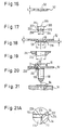
- Fig. 1 shows, initially in side view, an element 10 in accordance with the invention in the form of a threaded bolt having a head portion 12 and a shaft portion 16 provided with a thread 14.
- the element has concave, peripherally closed fields or pockets 20 at its underside 18 which serves as part of the contact surface.
- the fields 20 are at least partly bounded by ribs 22 which extend outwardly away from the shaft portion 16, with the shaft side parts 24 of the ribs, which are right-angled in side view, extending in raised form along the shaft portion 16 and merging at the ends 26 remote from the head portion into at least one recess 28.
- the recess 28 is spirally arranged around the shaft portion and is formed here as a thread groove, i.e. as a continuation of the thread 14 of the shaft portion 16.
- the closed fields 20 are bounded at their radially outer side by a circumferentially extending peripheral surface 30 of the head, with the ribs merging at their radially outer ends into this peripheral surface without steps. At their radially inner side the fields 20 are bounded by a cylindrical peripheral surface 32 of the shaft portion.
- the surfaces facing the shaft portion of the radially outwardly extending parts of the ribs 22 can also lie, contrary to the graphic illustration in Fig. 3, in the same plane as the peripheral surface 30 or they can, as can be seen from Fig. 3, extend obliquely to the plane 31 defined by the underside 30 of the head portion 12 and be set back from this plane so that they do not project beyond the shaft side of this plane.
- the peripheral surface 30 and also the shaft side surfaces of the radially extending regions of the ribs 22 form the actual contact surface of the head portion 12.
- the closed fields 20 are at least substantially square in this embodiment when seen in plan view and this is in practice a relatively favourable shape for the fields 20.
- Other shapes of the enclosed fields 20, i.e. fields 20 which are bounded at all sides, are also entirely conceivable in the context of the present invention.
- the rib parts 22 which are located in the contact region 18 of the head portion 12 and which preferably extend in the radial direction become broader in the radially outward direction with the special design of Figs. 2 and 4. They merge steplessly without interruption into the peripheral surface 30 of the head portion. In the present example eight ribs 22 are present, with the number of ribs preferably lying between six and eight.
- the peripherally closed fields 20 have their greatest depth (measured in the axial direction 35 of the element 10) adjacent to the shaft portion 16.
- the peripheral surface 30 on the shaft side surfaces of the ribs 22 principally belongs to the contact surface, the base surfaces of these closed fields can also be exploited as a contact surface by intentional deformation of the corresponding sheet metal component into the closed fields.
- the element of the invention it is possible, with the element of the invention, to provide a contact surface of large area so that the element can also be used with soft sheet metal components without having to fear that a critical surface pressure results.
- the base surfaces of the closed fields lie at least substantially on a conical surface with an enclosed angle of 130 to 140°, preferably 140°. This cone angle is indicated with the reference ⁇ in Fig. 3.
- the element has a centring recess 34 which ensures a high-quality guidance of the element during insertion of the same.
- the element has, moreover, a conical insertion tip 36. This tip is not only of use when attaching the article which is later to be secured to the element but rather also during the guidance of the element in the setting head during the insertion into the corresponding sheet metal component.
- the insertion method is schematically illustrated in Figs. 5 and 6.
- Fig. 5 shows a setting head 38 of a joining tool 40 comprising a pressing and joining plunger 42 which is moveable in the direction of the arrow 43.
- the arrow 43 shows the supply direction of the element 10 in the setting head.
- the elements 10 are fed individually to the setting head 38.
- the element shown in Fig. 5 passes under gravity, optionally also under the action of compressed air or of the pressing and joining plunger 42, through the bore 44 of the setting head until the head portion 12 of the element which is partly spherically rounded for guidance purposes enters into contact with a ball 48 biased by means of a spring 46.
- three such spring biased balls are preferably provided, which are arranged at intervals of 120° around the longitudinal axis 50 of the setting head 38.
- the pre-apertured sheet metal component 52 into which the element 10 is to be inserted is already held between the setting head 38 and the riveting die 54 of a lower tool 56.
- the shaft portion 16 of the element which is provided with a thread 14 has already partly passed through the pre-manufactured hole 58 in the sheet metal component 52 and through a cylinder-like centring opening 60 of the riveting die 54 which is coaxially aligned therewith.
- the riveting die or die button 54 itself is interchangeably supported within a bore 57 of the lower tool 56 belonging to the joining tool and is supported via a plate 59 on a lower press plate 61.
- the pressing and joining plunger 62 provided in the setting head moves further downwardly and presses the head portion 12 of the element past the three spring loaded balls 48.
- the crown region 64 of the riveting die 54 arranged coaxially to the hole 58 and to the axis 50 is pressed into the material of the sheet metal component and this leads to the material of the sheet metal component flowing on the one hand into the closed fields 20 and on the other hand into the recess 28 and thus producing a reliable riveted connection between the element 10 and the sheet metal component 52, which then jointly form a component assembly.
- the riveting die 54 has the shape in the crown region which can be seen from Fig. 7. I.e. this crown region of the riveting die has a ring-like, wave-shaped end face which has crests 72 and valleys 74 extending in the axial direction to generate the plastic deformation of the sheet metal material.
- the raised crests 72 serve to drive the material of the sheet metal into the concave fields 20 in the underside of the head portion 12 of the element 10.
- the valleys 74 come into contact against the sheet metal component in regions where the radially outwardly extending parts of the ribs 22 lie, so that a pronounced thinning of the sheet metal material does not arise in the region of the ribs in accordance with the invention.
- the sheet metal material is also forced to flow into the recess 28 so that the desired form-locked connection arises.
- a special measure for the angular alignment of the element 10 relative to the crests and valleys of the riveting die is in practice not necessary because, for energetic reasons, the element 10 attempts to turn in such a way that the potential energy is a minimum and thus adopts a position in which the crests 72 of the riveting die 54 are aligned with the concave fields 20, i.e. the requisite alignment takes place via a slight automatic turning of the element during the setting procedure.
- This groove has a wave-shaped base surface, above all when the riveting die has the shape of Fig. 7.
- the crests of the wave-shaped base surface should, however, not project beyond the lower side 7 of the sheet metal component in order to ensure a clean seat for the article which is to be secured to the sheet metal component.
- the crest regions of the wave-shaped base surface can project beyond the lower side of the sheet metal component in order to ensure a higher surface pressure at the terminal, i.e. a better electrical contact.
- the element of the invention can, however, also be differently formed than as a threaded bolt.
- an element 10 in the form of a bearing spigot could be considered. I.e. the thread is replaced or supplemented by a cylindrical bearing surface.
- the fastener element could be a nut element with the shaft portion being hollow.
- the end 100 of the bolt element 10 remote from the head portion 12 has a so-called Ka shape in accordance with DIN 78.
- the end 100 represents a spigot-like projection 101 with an outer diameter which is somewhat smaller than the core diameter of the thread 14 and merges via a truncated, cone-shaped section 102 into the thread 14, with the cone angle of the truncated, cone-shaped section which diverges in the direction of the thread 14 amounting to 90°.
- a plurality of wedge-shaped grooves 106 arranged parallel to the longitudinal axis are located at the periphery of the spigot-like projection 101 with the depth of the grooves (measured in the radial direction) reducing continuously from the end face 104 of the shaft portion 16 and going to zero at the start of the conical section 102.
- the basic Ka-shape of the end of a bolt element is admittedly known per se; it is, however, normally used for a quite different purpose, namely to enable the attachment of a nut, using automatic screwing devices in particular.
- the wedge-shaped grooves are a special feature of the present design and should not be confused with the longitudinal grooves sometimes provided in the lower part of the thread cylinder of a bolt for paint stripping purposes.
- the number of the wedge-shaped grooves is not so critical for the present invention. It is, however, particularly advantageous if a non-even number of such grooves 106, for example 3 or 5 such grooves, is/are provided.
- Each groove is of V-shaped cross section, e.g. of a 90° inclined angle, with the one side surface of the groove, for example the side surface 108 in Fig. 10, lying in a radial plane, while the other surface forms an angle with the radial surface 108.
- the base of the V-shaped grooves preferably subtends an inclined angle of about 10 ⁇ to the longitudinal axis.
- the grooves appear fairly narrow as a result of their shadow depth.
- the grooves or other notching features are not essential with normal strength sheet metal when a Ka-shape alone will suffice.
- the grooves or other notching features are, however, of advantage with high strength sheet metal, which is increasingly being used in motorcar production.
- the end face of the spigot is preferably flat and perpendicular to the axis of the element; it could, however, be slightly convex or slightly concave, with the convex shape being preferable to the concave shape.
- Fig. 10 represents a preferred embodiment, other embodiments can also be considered.
- the grooves 106 in accordance with Fig. 10 could be formed as ribs. These ribs should lie within a circle coaxial to the longitudinal axis 50 of the bolt element, with the diameter of the circle being smaller than the core diameter of the thread 14.
- the end face 104 can also be slightly concave or convex and could also be formed as a point, e.g. an ASP point in accordance with DIN 78.
- the pointed shape is, however, not particularly preferred because problems arise if the bolt element is not guided absolutely perpendicular to the sheet metal component. If only a slight tilting of the bolt element arises in the setting head, for example when the latter is somewhat worn, then an end of the bolt element formed as a point would be pressed into the sheet metal component. A correction of the inclined position of the bolt element would then no longer be possible, i.e. the use of a bolt element with a pointed end is only restrictively capable of satisfying the demands of the installation process.
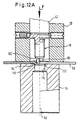
- Fig. 12 shows the bolt element 10 in the setting head 38 and indeed during a working stroke of a non illustrated press in which the setting head 38 and the riveting die 54 are provided.
- the setting head 38 is namely secured to an upper tool (not shown) or to an intermediate plate (not shown) of the press and has been driven downwardly to the extent that the sheet metal component 52 is clamped between the end face of the setting head 38 and the oppositely disposed end face of the die 54.
- the ring-shaped raised portion 64 at the end face of the die 54 which can be formed in accordance with Fig. 7, has caused a slight upwardly directed bulge of the sheet metal component 52.
- the plunger 52 is moved further downwardly while the part of the setting head indicated in hatched lines deflects resiliently rearwardly relative to the upper tool of the press or of the intermediate plate of the latter.
- the plunger 42 has moved downwardly to the extent that the end face 104 of the bolt element just contacts the sheet metal component 52. From Fig. 12 one can clearly see that the outer diameter of the spigot-like end 101 of the bolt element is substantially smaller than the inner diameter of the tapered ring recess 112 at the end face of the die.
- the spigot-like projection 101 at the end 100 of the bolt element which acts as a cutting projection contacts the sheet metal component 52 which lies between the cutting projection and the die 54 lying beneath it, which is aligned coaxial to the central longitudinal axis 50 of the bolt element.
- the tapered ring recess 112 of the die merges via a ring shoulder in the form of a flat shoulder 113 into a section 114 with a diameter which is smaller than the smallest inner diameter of the tapered ring-shaped recess 112, but is, however, ca. 0.1 mm larger than the outer thread diameter of the bolt element 10.
- the precise shape of the tapered ring-shaped recess 112 is shown later in Figs. 21 and 21A.
- the transition from the tapered recess to the flat shoulder can be rounded.
- the transition from the ring shoulder 113 into the bore 114 can also be formed as a rounded shoulder rather than as a right angle. Amongst other things, this can assist in the guidance of the bolt element 10.
- the die 54 is held and secured in known manner in a stamping / shaping tool or in a press.
- Fig. 12A the setting plunger has moved further downwardly and the tip of the bolt element has depressed the sheet metal into the tapered recess 112 of the die button 54.
- the stress in the sheet metal has increased to a value which is only fractionally below the stress necessary for piercing of the sheet metal 52.
- a collar 120 has been at least partly preformed at this stage. Only a slight further downward movement of the plunger 52 is required to reach the situation in Fig. 13 in which the bolt element has cut a slug 116 from the sheet metal component 52 under the influence of the force F resulting from the stroke movement of an upper tool of the press.
- the panel is initially formed into a cone shape in the region beneath the fastener element in the phase in which the slug is cut from the panel.
- the cone shape is drawn and/or dilated as the conical portion 102 of the fastener (Fig. 10) is driven through the cone-shaped panel portion and has thereby generated a tubular deformation, i.e. a collar or flare, 120 in the shaped sheet metal component 52, with the tubular deformation being directed in the direction of the free space 118 of the die.
- a tubular deformation i.e. a collar or flare
- the side edges 117 of the slug 116 are rough, and this also applies to the downwardly directed end face of the ring-like collar 120, i.e. of the tubular portion.
- the slug 116 is slightly dished as a result of it being stamped from an unsupported portion of the sheet metal component.
- the wedge-shaped grooves have generated notches, cuts or tears in the sheet metal component which are particularly advantageous because they tear further under the action of the truncated, cone-shaped section 102 and reduce the forces which are necessary for the deformation of the sheet metal component in the area of the collar.
- the bolt element has moved, as a consequence of the downwardly directed movement of the upper tool (riveting plunger 42), which causes a corresponding movement of the plunger 42, into the bore 124 of the die which forms a guide. In doing so it has further broadened the tubular section of Fig. 13 and has largely moulded it in a form fitted manner into the ring recess 112 of the die.
- This shaping of the sheet metal material takes place essentially by the first two thread turns of the bolt element.
- These thread turns can be made substantially harder and of higher strength using a known heat treating process than the following thread turns which are associated with a specific strength class, for example 8.8. Damage to these thread turns is avoided by the increased strength.
- the hardening of the first thread turns of a bolt element is known per se in the art, and above all for self-tapping bolts. This increased strength can also be achieved with means known per se.
- the punched slug 116 drops in the drawing of Fig. 14 through the free space 118 of the die 54 and can be disposed of in known manner.
- the collar 120 makes material available in the critical region and this material is pressed during the deformation which occurs during closing of the press in a more complete manner into the ring recess and into the closed fields of the bolt element, whereby a higher permanent stress can be achieved in this region, which is favourable for the strength of the connection.
- the component assembly of Fig. 11 results after opening of the press and removal of the sheet metal component with the bolt element riveted to it.
- This collar which can conveniently be formed during the piercing operation, e.g. by a suitably shaped hole punch, (such as one resembling the end of the tip pierce bolt described above), will be the same, or at least approximately the same, in shape as the collar 120 shown in Figs. 11, 14 and 15 of the present application.
- the material of the collar will then be squeezed, in the same way as shown in Figs. 14 and 15, so that it flows essentially radially into the radial groove or thread turns of the fastener element to generate the resistance to push-out.
- This design has a further advantage.
- connection that is produced between the fastener element and the sheet metal has a very high resistance to forces or force components acting transversely to the longitudinal axis of the fastener element which effectively try to lever the fastener element out of the sheet metal by a type of "unbuttoning" action, i.e. to forces acting for example in the direction K in Fig. 11.
- the previously known elements have a relatively low resistance to such lever forces.
- the component assembly of the present invention i.e. the fastener element and sheet metal assembly, e.g. of Fig. 11, has a substantially higher resistance to such forces.
- a die button having a ring nose disposed coaxial to and radially outside of the ring recess 112 of Fig. 12.
- This ring nose may either have the shape shown in Fig. 7 or may alternatively be a ring nose 64 of constant, approximately roof-shaped cross-section, for example as shown in Fig. 15, and as shown in more detail in Figs. 21 and 21A.
- cylindrical wall 115 of the ring recess 112 is slightly tapered in the direction away from the head of the fastener element.
- this tapering surface helps deform the material of the collar 120 radially inward l y into the radial groove or turns of the thread. This movement of metal is also favoured by the shaping surfaces of the concave fields 20, i.e. by the angle à (Fig. 3).
- the radial surface 113 at the base of the ring recess 112 ensures a clean termination to the collar after fitting of the fastener element and ensures that the collar material does not protrude axially to an extent which could lead to an unsatisfactory connection to a further sheet metal component to be bolted to the first. Furthermore, this surface 113 also aids in the radial deformation of the collar material by ensuring that it cannot deviate axially in the direction away from the head of the fastener element.
- the surface 113 helps ensure that the deformed sheet metal material fills out the concave fields 20.
- the collar 120 When the collar 120 is preformed prior to insertion of the fastener element, it should preferably have an inner diameter equal to or fractionally smaller than the maximum diameter of the fastener element in the region of the radial groove or last thread turns. The provision of such a collar by a pre-piercing operation is also beneficial in facilitating centring of the fastener element during its insertion into the pre-pierced hole.
- the die button is shaped in a similar way so that a collar which projects beyond the plane of the sheet metal component away from the head of the fastener element is also created here, in particular when using a die button with a ring nose 64 as described above.
- good values of lever out resistance can be achieved with both thick and thin sheet metal components.
- the outside shape of the collar 120 is slightly conical - both with thin sheet metal and with thick sheet metal and this facilitates the centring of another sheet metal component placed over the shaft end of the fastener element and which is to be clamped against the sheet metal component 52.
- the radially extending portions of the ribs 22 need not fully bound the concave fields 20 but could instead only extend pathway along the radial boundaries of those fields.
- Fig. 16 which is not in accordance with the present invention shows a sheet metal component 52, having a plane cylindrical hole 58 preformed therein. This may, for example, be done by punching or by drilling. It will be noted that the sheet metal has a thickness S which is greater than 2.25 mm. With panel thicknesses greater than 2.25 mm it is namely sufficient to prepare the panel by forming such a simple cylindrical hole 58.
- the panel is prepared so that it has an aperture 58 with a ring collar or flare 120 which is formed by a hole punch 200, having the shape shown in Fig. 17.
- the hole punch 200 has a cylindrical spigot 202 at its front end, with the cylindrical spigot 202 having a planar end face 204 perpendicular to the central longitudinal axis 206 of the hole punch.
- the circular edge 208 formed at the intersection of the front end face 204 with the cylindrical wall of the spigot 202 is a cutting edge.
- the punching of the hole 58 is effected using a die button 214, the end face of which confronting the hole punch is shown in a longitudinal section in Fig. 19.
- the die button has a cylindrical central bore having a diameter C which merges at the front end face of the die button 214 via a radius 216 into the flat end face of the die button.
- the corresponding dimension C is also entered into Fig. 18 and it can be seen that this corresponds to the maximum outer diameter of the generally conical collar 120 and that the radiussed shoulder 216 has formed a corresponding radius 218 at the point where the collar blends into the plane of the sheet metal component 52.
- the diameter D of the aperture 58 is just fractionally greater than the diameter of the cylindrical portion 214 of the hole punch 200.
- the initial punching is carried out by the cylindrical spigot 202 with the sheet metal panel being supported on the die button 214 at a diameter substantially greater than the diameter F of the cylindrical spigot 202 of the hole punch 200.
- This again leads to the panel material being depressed before the slug (not shown) is punched out from it, as shown in Fig. 12A.
- the shoulder 208 with the radius 212 completes the shaping of the flare or aperture in the sheet metal component, leading to a shape as shown in Fig. 18.
- the height H and the edge shape of the collar are not specifically defined, they simply arise naturally through the cooperation of the hole punch with the die button. This means that the end of the collar is slightly uneven, as shown in Fig. 18.
- the height H of the collar is typically a minimum of 1.5 mm irrespective of the precise thickness S of the sheet metal component 52.
- the diameter D is made just fractionally larger than the nominal outside thread diameter of the bolt element used, e.g. D is made about 0.1 mm greater than the nominal bolt diameter.
- Fig. 20 shows a sketch illustrating the component assembly after a bolt element 10 of the preferred type, which will subsequently be discussed with reference to Figs. 22 and 23, has been pressed into the sheet metal component 52 using a setting head such as 38 in Fig. 12 in cooperation with a die button 54, which is shown in more detail in Fig. 21.
- the precise shape of the end face of the die button 54 is shown to an enlarged scale in Fig. 21A, which actually shows in a circle the portion of the die button 54 circled in Fig. 21.
- the die button has a ring nose 64, having a generally roof-like shape with sloping flanks, with the outer flank 222 merging into the planar end face 224 of the die button, and with the inclined inner flank 226 merging into a cylindrical recess 228 within. the central bore 114 of the die button.
- the sloping flank 226 results in a tapered recess 112 as previously described with reference to Figs. 12 to 15.
- the cylindrical recess 228 has a flat shoulder 113 at its bottom, which in use contacts the end of the collar 120 of Fig. 18 and determines the maximum axial projection of the collar once the bolt element 10 has been fitted.
- Fig. 20 also clearly shows the ring recess 232 formed by the ring nose 64 of the die button 54. It will be noted that the panel material has been deformed so that it fills the concave fields such as 20 beneath the head of the bolt element 10 and that the collar 120 has been pushed radially into engagement with the threads immediately beneath the head of the bolt element 10.
- the radial thickness of the collar generally tapers from the base of the ring groove 232 towards the axial end of the deformed collar remote from the head portion 12 of the bolt element.
- a die button 54 is used of the same general shape as that shown in Figs. 21 and 21A, and this results in the formation of a shape of the sheet metal in the region of engagement with the bolt element which corresponds precisely to that of Fig. 20, i.e. a collar is also formed in this case by plastic flow of the sheet metal as a result of the cooperation of the die button 54 and the setting head acting on the bolt element 10.
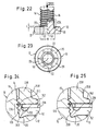
- Fig. 22 shows to an enlarged scale a side view, partly in a longitudinal section, of the preferred design of the head portion 12 and the shaft portion 16 of the bolt element 10 in the region adjacent the head portion 12.
- the ribs 22 have portions which extend axially along the shaft portion 16 of the bolt element 10, and indeed over a length L which depends on the precise size of the bolt and which, for example, for a 5 mm metric bolt, would be equal to 0.5 mm.
- the thread 14 of the bolt is rolled onto the shaft portion 16 of the bolt element after formation of the remainder of the bolt element by cold heading.
- the thread which is intended to receive the nut has the diameter G but is continued in the region 234 over approximately three thread turns, in a region of the shaft of a slightly greater diameter H.
- the collar is brought into engagement with the thread in the portion 234, i.e. with the threads in the region of a greater diameter H.
- Fig. 24 shows a partial longitudinal section of a component assembly comprising the bolt element 10 installed in a sheet metal component 52, with a further sheet metal component 236 placed onto the sheet metal component 52 and secured to it by a nut element 238 which engages with the thread cylinder 14 of the shaft portion 16 of the bolt element 10.
- Fig. 24 also clearly shows the ring recess 232 provided in the sheet metal component 52 and the collar 120 after it has been radially deformed to engage with 2 to 2 1/2 threads in the region 234.
- the further sheet metal component 236 has a central aperture 240 which fits over the radially deformed collar 120 with a slight clearance 250 being left between the rim of the aperture 240 and the collar 120.
- the nut 238 is a typical nut used nowadays in the motor industry and has an integral flange 242 for load spreading. It also has a chamfer 246 adjacent the threaded portion of its bore. In it usual way it also has a polygonal outer surface 248 for the application of a spanner or wrench.
- the ring groove 232 represents a void there is still more than adequate contact area of the load transmitting part between the nut and the bolt element so that surface pressures are kept well within the value at which a permanent deformation of the components could be expected.
- Fig. 25 is basically a diagram similar to Fig. 24 but showing the situation in which the further sheet metal component 236 is eccentrically positioned relative to the axis 50 of the bolt element (not shown) rather than concentrically positioned as in Fig. 24.
- This eccentric positioning manifests itself by a larger gap 250 on one side of the bolt element than is the case in Fig. 24.
- Such eccentric arrangements are to be expected in practice because of tolerance considerations, particularly when the further sheet metal component 236 has to fit over more than one bolt element 10. It has been shown that the surface pressures within the clamped assembly comprising the nut, the bolt and the two sheet metal components can be kept within acceptable limits within the normal tolerances to be expected with respect to eccentricity and hole size. Interestingly, this is also achieved with head diameters of the bolt elements of favourable size in comparison to other known fasteners.
- elements in accordance with the present invention will typically be formed of a middle carbon steel, e.g. a 35B2 medium carbon steel in accordance with German Industrial Standard DIN 1654 equivalent to an S 1035 steel in the USA.
- a middle carbon steel e.g. a 35B2 medium carbon steel in accordance with German Industrial Standard DIN 1654 equivalent to an S 1035 steel in the USA.
Landscapes
- Engineering & Computer Science (AREA)
- Mechanical Engineering (AREA)
- General Engineering & Computer Science (AREA)
- Connection Of Plates (AREA)
- Insertion Pins And Rivets (AREA)
- Automatic Assembly (AREA)
Applications Claiming Priority (3)
| Application Number | Priority Date | Filing Date | Title |
|---|---|---|---|
| DE19535537 | 1995-09-25 | ||
| DE19535537A DE19535537A1 (de) | 1995-09-25 | 1995-09-25 | Bolzenelement, Verfahren zum Einsetzen desselben, Zusammenbauteil und Nietmatrize |
| PCT/EP1996/004188 WO1997011811A1 (en) | 1995-09-25 | 1996-09-25 | Method of inserting a fastener element, bolt element, riveting die and component assembly |
Publications (2)
| Publication Number | Publication Date |
|---|---|
| EP0958100A1 EP0958100A1 (en) | 1999-11-24 |
| EP0958100B1 true EP0958100B1 (en) | 2003-11-26 |
Family
ID=7773069
Family Applications (1)
| Application Number | Title | Priority Date | Filing Date |
|---|---|---|---|
| EP96933386A Expired - Lifetime EP0958100B1 (en) | 1995-09-25 | 1996-09-25 | Method of inserting a fastener element, bolt element, riveting die and component assembly |
Country Status (11)
| Country | Link |
|---|---|
| US (1) | US7401394B1 (enExample) |
| EP (1) | EP0958100B1 (enExample) |
| JP (1) | JP4052669B2 (enExample) |
| KR (1) | KR100460232B1 (enExample) |
| CN (1) | CN1105832C (enExample) |
| AU (1) | AU7214296A (enExample) |
| BR (1) | BR9610709A (enExample) |
| CA (1) | CA2232295C (enExample) |
| DE (2) | DE19535537A1 (enExample) |
| MX (1) | MX9802172A (enExample) |
| WO (1) | WO1997011811A1 (enExample) |
Cited By (5)
| Publication number | Priority date | Publication date | Assignee | Title |
|---|---|---|---|---|
| DE102004020676A1 (de) * | 2004-04-28 | 2005-11-24 | Profil-Verbindungstechnik Gmbh & Co. Kg | Verfahren und Vorrichtung zur Anbringung eines Befestigungselements an ein Bauteil, insbesondere an ein Blechteil |
| DE102004030223A1 (de) * | 2004-06-23 | 2006-01-12 | Profil Verbindungstechnik Gmbh & Co. Kg | Verfahren zur Herstellung eines Zusammenbauteils bestehend aus einem Blechteil und einem an diesem angebrachten Funktionselement, Blechteil sowie Funktionselement |
| DE102004043688A1 (de) * | 2004-06-23 | 2006-04-06 | Profil-Verbindungstechnik Gmbh & Co. Kg | Verfahren zur Herstellung eines Zusammenbauteils bestehend aus einem Blechteil und einem an diesem angebrachten Funktionselement, Blechteil sowie Funktionselement |
| EP2019214A2 (de) | 2007-07-26 | 2009-01-28 | PROFIL-Verbindungstechnik GmbH & Co. KG | Einpresselement zum Einpressen in ein nicht gelochtes oder gelochtes Bauteil sowie Verfahren zur Herstellung des Einpresselements |
| US8533928B2 (en) | 2004-04-28 | 2013-09-17 | Profil Verbindungstechnik Gmbh & Co., Kg | Method and apparatus for the attachment of a fastener element to a component, in particular to a sheet metal part |
Families Citing this family (61)
| Publication number | Priority date | Publication date | Assignee | Title |
|---|---|---|---|---|
| DE19734539C2 (de) * | 1997-07-30 | 1999-07-22 | Brose Fahrzeugteile | Bauteilverbindung |
| DE19815407A1 (de) * | 1998-04-06 | 1999-10-07 | Profil Verbindungstechnik Gmbh | Verbindungseinrichtung zum Verbinden zweier Bauteile, Kombination der Verbindungseinrichtung mit den beiden Bauteilen und Verfahren zur Herstellung einer Verbindung zwischen zwei Bauteilen |
| CA2287668A1 (en) * | 1998-12-28 | 2000-06-28 | William F. Hartery | Plate and bolt assembly |
| CN1241140C (zh) * | 1999-02-01 | 2006-02-08 | 纽约市哥伦比亚大学托管会 | 生成多媒体档案描述的系统和方法及生成档案描述文件的方法 |
| US7731467B2 (en) | 1999-07-09 | 2010-06-08 | Profil Verbindungstechnik Gmbh & Co., Kg | Bolt element having a shaft part and a spherical head, component assembly and method for the manufacture of a bolt element |
| DE20012097U1 (de) | 2000-07-12 | 2000-12-28 | Textron Verbindungstechnik GmbH & Co. oHG, 56567 Neuwied | Verdreh- und auspreßsicher in ein Blech einpreßbares Befestigungselement |
| DE50105567D1 (de) | 2000-12-29 | 2005-04-14 | Profil Verbindungstechnik Gmbh | Bolzenelement mit einem Schaftteil und einem Kugelkopf, Zusammenbauteil und Verfahren zur Herstellung eines solchen Bolzenelements |
| DE10259370B3 (de) * | 2002-12-18 | 2004-04-08 | Sfs Intec Holding Ag | Stanzniet |
| DE10353642A1 (de) | 2003-11-17 | 2005-07-07 | Profil Verbindungstechnik Gmbh & Co. Kg | Funktionselement, Zusammenbauteil bestehend aus dem Funktionselement in Kombination mit einem Blechteil, Verfahren zur Herstellung des Zusammenbauteils sowie Verfahren zur Herstellung des Funktionselements |
| JP4673730B2 (ja) * | 2005-11-25 | 2011-04-20 | 日東精工株式会社 | ボス部材及びボス部材の製造方法 |
| CN102889275B (zh) * | 2006-06-05 | 2014-07-16 | 形状连接技术有限公司及两合公司 | 连接元件,零件总成和形成该零件总成的方法 |
| DE102007039204A1 (de) * | 2007-08-03 | 2009-02-05 | Wabco Gmbh | Verfahren zur Montage von Befestigungsschrauben an einem Bremszylinder |
| EP3354243A1 (en) | 2007-11-21 | 2018-08-01 | Smith & Nephew PLC | Wound dressing |
| DE102008014840A1 (de) * | 2008-03-07 | 2009-09-10 | Adolf Würth GmbH & Co. KG | Befestigungselement |
| US8123311B2 (en) * | 2008-04-23 | 2012-02-28 | Robert Nilsson | Portable display system and associated methods |
| DE102008032694A1 (de) * | 2008-07-03 | 2010-01-07 | Arnold & Shinjo Gmbh & Co. Kg | Vorrichtung zum Einpressen von Befestigungselementen |
| JP4832480B2 (ja) * | 2008-08-08 | 2011-12-07 | 八千代工業株式会社 | 燃料タンクの保護板取付構造 |
| JP2010071401A (ja) * | 2008-09-19 | 2010-04-02 | Pias Hanbai Kk | クリンチボルト |
| DE102009035338A1 (de) * | 2009-07-22 | 2011-01-27 | Arnold & Shinjo Gmbh & Co. Kg | Befestigen von Nietelementen |
| DE102009042336A1 (de) * | 2009-09-21 | 2011-03-24 | Profil Verbindungstechnik Gmbh & Co. Kg | Selbststanzendes hohles Einpresselement, Zusammenbauteil bestehend aus einem Einpresselement und einem Blechteil sowie ein Verfahren zur Herstellung einer selbststanzenden Einpressmutter sowie zur Anbringung einer selbststanzenden Einpressmutter |
| DE102010000217A1 (de) * | 2010-01-27 | 2011-07-28 | ContiTech Luftfedersysteme GmbH, 30165 | Trägerplatte mit Schraubbefestigung |
| US9061095B2 (en) | 2010-04-27 | 2015-06-23 | Smith & Nephew Plc | Wound dressing and method of use |
| CN101890564A (zh) * | 2010-07-06 | 2010-11-24 | 上海交通大学 | 异种金属电阻铆焊装置 |
| US20120042711A1 (en) * | 2010-08-20 | 2012-02-23 | Gregg Vincent Summers | Panel screw clinching anvil |
| DE102010039669A1 (de) * | 2010-08-24 | 2012-03-01 | Adolf Würth GmbH & Co. KG | Befestigungselement |
| GB201017004D0 (en) * | 2010-10-08 | 2010-11-24 | Henrob Ltd | Fastener delivery apparatus |
| KR101082263B1 (ko) * | 2010-10-27 | 2011-11-09 | 엘에스산전 주식회사 | 링 단자 연결용 커넥터 |
| DE102011009012A1 (de) * | 2011-01-20 | 2012-07-26 | Profil Verbindungstechnik Gmbh & Co. Kg | Funktionselement in Form eines Einpresselements |
| DE102011103723A1 (de) * | 2011-05-31 | 2012-12-06 | Airbus Operations Gmbh | Verbindungsanordnung, insbesondere für Flugzeugstrukturteile |
| JP5830819B2 (ja) * | 2011-06-21 | 2015-12-09 | ポップリベット・ファスナー株式会社 | 金属カラーの取付方法 |
| DE102011108224A1 (de) * | 2011-07-21 | 2013-01-24 | Profil Verbindungstechnik Gmbh & Co. Kg | Funktionselement mit Verdrehsicherungsmerkmalen sowie Zusammenbauteil bestehend aus dem Funktionselement und einem Blechteil |
| DE102012001086A1 (de) * | 2012-01-20 | 2013-07-25 | Profil Verbindungstechnik Gmbh & Co. Kg | Bolzenelement und Verfahren zur Anbringung eines Bolzenelements an einem Bauteil aus einem Verbundwerkstoff |
| JP2013177934A (ja) * | 2012-02-28 | 2013-09-09 | Sakata Seisakusho:Kk | ボルトの固定方法、被固定体およびボルト固定用金型 |
| DE102013204958A1 (de) | 2012-03-27 | 2013-10-02 | Profil Verbindungstechnik Gmbh & Co. Kg | Funktionselement in Form eines Einpresselements |
| US9435362B2 (en) | 2014-03-05 | 2016-09-06 | Morgan Truck Body, Llc | Bolt and nut assembly with plastic cover for controlled sealing compression |
| CN105013915B (zh) * | 2014-04-29 | 2017-05-10 | 美的集团股份有限公司 | 电机支架的加工方法 |
| DE102014211656A1 (de) * | 2014-06-18 | 2016-01-07 | Bayerische Motoren Werke Aktiengesellschaft | Verfahren zum Verpressen einer Kugel mit einem ersten Bauteil sowie Bauteilverbindung |
| DE102014009410B4 (de) | 2014-06-25 | 2018-04-05 | Audi Ag | Verfahren zum Verbinden eines Einpressbolzens mit einem ein Vorloch aufweisenden Blechteil und Abdeckelement zur Durchführung des Verfahrens |
| JP6287891B2 (ja) * | 2015-02-24 | 2018-03-07 | 株式会社オートネットワーク技術研究所 | 電気接続箱及び接続端子部品 |
| JP6252872B2 (ja) * | 2015-02-24 | 2017-12-27 | 株式会社オートネットワーク技術研究所 | 電気接続箱及び接続端子部品 |
| CN105215928B (zh) * | 2015-11-05 | 2017-02-01 | 深圳创新设计研究院有限公司 | 一种批量装配铆钉套件的装置 |
| CN105234667A (zh) * | 2015-11-09 | 2016-01-13 | 珠海格力电器股份有限公司 | 一种铆接工装 |
| US10228684B2 (en) * | 2015-11-23 | 2019-03-12 | The Boeing Company | Automated fastener insert installation system for composite panels |
| JP6214696B2 (ja) * | 2016-03-02 | 2017-10-18 | 株式会社青山製作所 | かしめボルト |
| JP6791738B2 (ja) * | 2016-11-30 | 2020-11-25 | 住友理工株式会社 | ボルト植設構造とそれを用いたアッパサポート、ボルト植設構造の製造方法 |
| DE102017200575B4 (de) * | 2017-01-16 | 2025-10-30 | Bayerische Motoren Werke Aktiengesellschaft | Verfahren zum Herstellen eines Bauteils |
| CN106826208A (zh) * | 2017-03-23 | 2017-06-13 | 苏州三铁电气有限公司 | 自动拉铆机 |
| JP7046427B2 (ja) * | 2017-05-30 | 2022-04-04 | 株式会社青山製作所 | 締結構造 |
| DE102018211566A1 (de) | 2018-07-12 | 2020-01-16 | Bayerische Motoren Werke Aktiengesellschaft | Werkzeug und Verfahren zum Verpressen eines Hilfsfügeelements mit einem separat von dem Hilfsfügeelement ausgebildeten Werkstück, insbesondere zum Herstellen eines Kraftfahrzeugs |
| DE102018117131A1 (de) | 2018-07-16 | 2020-01-16 | Profil Verbindungstechnik Gmbh & Co. Kg | Selbststanzendes Element und Zusammenbauteil bestehend aus dem Element und einem Blechteil |
| US10756453B2 (en) * | 2018-08-20 | 2020-08-25 | Twisted Ideas, Inc. | Quick connection system |
| CN109424610B (zh) * | 2018-11-15 | 2023-07-25 | 宾科精密部件(中国)有限公司 | 压铆件 |
| CN110640070A (zh) * | 2019-11-14 | 2020-01-03 | 辽宁忠旺铝合金精深加工有限公司 | 一种提高抗转动能力拉铆螺母的安装方法 |
| CN111468927B (zh) * | 2020-04-23 | 2022-07-01 | 上海电机学院 | 一种多类型轴承的安装压紧装置 |
| DE102020111696A1 (de) | 2020-04-29 | 2021-11-04 | Profil Verbindungstechnik Gmbh & Co. Kg | Funktionselement |
| CN113084017A (zh) * | 2021-04-02 | 2021-07-09 | 无锡华光轿车零件有限公司 | 一种改善螺钉铆接性能的安装工艺 |
| CN113305217A (zh) * | 2021-05-17 | 2021-08-27 | 江苏盾安环控系统有限公司 | 一种核电站用调节阀叶片连接方法 |
| US11820037B2 (en) | 2021-08-02 | 2023-11-21 | Emerson Professional Tools, Llc | Punch and draw stud having multi-start threads, and method of engaging same |
| CN115673126B (zh) * | 2022-11-23 | 2024-05-14 | 广东敏卓机电股份有限公司 | 一种电机定子的铆轴机构及其铆轴方法 |
| DE202022107012U1 (de) * | 2022-11-29 | 2024-03-14 | Brose Fahrzeugteile SE & Co. Kommanditgesellschaft, Würzburg | Bauteilverbindung |
| US20240392825A1 (en) * | 2023-05-26 | 2024-11-28 | Arkansas Bolt Co., Inc. | Rivet Nut |
Citations (1)
| Publication number | Priority date | Publication date | Assignee | Title |
|---|---|---|---|---|
| EP0879679A2 (de) * | 1997-04-25 | 1998-11-25 | HILTI Aktiengesellschaft | Setzgerät für Ankerstangen von Verbundankern |
Family Cites Families (23)
| Publication number | Priority date | Publication date | Assignee | Title |
|---|---|---|---|---|
| GB949811A (en) * | 1961-12-29 | 1964-02-19 | Belling & Lee Ltd | Improvements in or relating to securing inserts in sheet material |
| US3782436A (en) * | 1972-07-21 | 1974-01-01 | J Steiner | Clinch stud |
| US3827131A (en) * | 1973-02-05 | 1974-08-06 | R Coltrin | Method of swage nail fastening |
| US3967669A (en) * | 1974-05-06 | 1976-07-06 | Textron, Inc. | Clinch type fastener |
| US4555838A (en) * | 1983-03-28 | 1985-12-03 | Multifastener Corp. | Method of installing self-attaching fasteners |
| DE3003908C2 (de) * | 1980-02-02 | 1984-10-18 | Profil-Verbindungstechnik Gmbh & Co Kg, 6382 Friedrichsdorf | Stehbolzen mit Stanz- und Nietverhalten |
| US4389766A (en) * | 1980-06-06 | 1983-06-28 | The Lamson & Sessions Co. | Method of mounting a fastener |
| US5174018A (en) * | 1981-01-28 | 1992-12-29 | Multifastener Corporation | Die button with staking features |
| GB2112893B (en) * | 1981-12-11 | 1985-05-30 | Avdel Ltd | Electrically conductive pin and method of installation thereof |
| CA1228255A (en) * | 1982-04-30 | 1987-10-20 | Edwin G. Sawdon | Self-attaching fastener and method of securing same to sheet material |
| GB2161571B (en) * | 1984-07-09 | 1987-12-31 | Tolwood Multifasteners | Pierce nut, panel assembly and attachment method |
| US4637766A (en) * | 1985-06-17 | 1987-01-20 | Textron Inc. | Clinch type fastener |
| DE3704763C1 (en) * | 1987-02-16 | 1988-10-13 | Voit Willy Gmbh & Co | Connection between a bolt, which has a head, and a metal sheet |
| US5140735A (en) * | 1990-01-16 | 1992-08-25 | Multifastener Corporation | Die member for attaching a self-piercing and riveting fastener |
| DE4003374C1 (enExample) * | 1990-02-05 | 1991-05-08 | Sfs Stadler Holding Ag, Heerbrugg, Ch | |
| US5423645A (en) * | 1993-08-04 | 1995-06-13 | Profil Verbindungstechnik Gmbh & Co. Kg | Fastener and panel assembly |
| DE4410475A1 (de) * | 1994-03-25 | 1995-09-28 | Profil Verbindungstechnik Gmbh | Vernietbares Element, Zusammenbauteil mit einem vernietbaren Element sowie Nietmatrize und Verfahren zur Herstellung des Zusammenbauteils |
| EP0553822B1 (en) * | 1992-01-31 | 1996-11-27 | Multifastener Corporation | Self-attaching fastener and installation die |
| ATE152216T1 (de) * | 1992-07-07 | 1997-05-15 | Bergner Richard Gmbh Co | Verfahren zur herstellung eines auspress- und drehfesten verbundteils durch einpressen eines einpressteils in ein blechteil sowie dafür geeignete einpressteile |
| DE4333052C2 (de) * | 1993-09-29 | 2002-01-24 | Audi Ag | Selbststanzende Befestigungsvorrichtung |
| US6125524A (en) * | 1994-03-25 | 2000-10-03 | Multifastener Corporation | Rivetable element, assembly, method of assembly and riveting die |
| WO1995027147A1 (en) * | 1994-04-04 | 1995-10-12 | Textron Inc. | Staked fastener with undercut |
| US6257814B1 (en) * | 1995-08-18 | 2001-07-10 | Profil Verbindungstechnik & Co. | Self-attaching fastener, method of forming same and method of attachment |
-
1995
- 1995-09-25 DE DE19535537A patent/DE19535537A1/de not_active Withdrawn
-
1996
- 1996-09-25 BR BR9610709A patent/BR9610709A/pt not_active IP Right Cessation
- 1996-09-25 CA CA002232295A patent/CA2232295C/en not_active Expired - Lifetime
- 1996-09-25 US US09/029,425 patent/US7401394B1/en not_active Expired - Fee Related
- 1996-09-25 JP JP51313697A patent/JP4052669B2/ja not_active Expired - Fee Related
- 1996-09-25 CN CN96197898A patent/CN1105832C/zh not_active Expired - Fee Related
- 1996-09-25 DE DE69630901T patent/DE69630901T2/de not_active Expired - Lifetime
- 1996-09-25 EP EP96933386A patent/EP0958100B1/en not_active Expired - Lifetime
- 1996-09-25 AU AU72142/96A patent/AU7214296A/en not_active Abandoned
- 1996-09-25 KR KR10-1998-0702161A patent/KR100460232B1/ko not_active Expired - Fee Related
- 1996-09-25 WO PCT/EP1996/004188 patent/WO1997011811A1/en not_active Ceased
-
1998
- 1998-03-19 MX MX9802172A patent/MX9802172A/es unknown
Patent Citations (1)
| Publication number | Priority date | Publication date | Assignee | Title |
|---|---|---|---|---|
| EP0879679A2 (de) * | 1997-04-25 | 1998-11-25 | HILTI Aktiengesellschaft | Setzgerät für Ankerstangen von Verbundankern |
Cited By (11)
| Publication number | Priority date | Publication date | Assignee | Title |
|---|---|---|---|---|
| DE102004020676A1 (de) * | 2004-04-28 | 2005-11-24 | Profil-Verbindungstechnik Gmbh & Co. Kg | Verfahren und Vorrichtung zur Anbringung eines Befestigungselements an ein Bauteil, insbesondere an ein Blechteil |
| US7735209B2 (en) | 2004-04-28 | 2010-06-15 | Profil Verbindungstecnik Gmbh & Co., Kg | Method and apparatus for the attachment of a fastener element to a component, in particular to a sheet metal part |
| US7752879B2 (en) | 2004-04-28 | 2010-07-13 | Profil Verbindungstechnik Gmbh & Co., Kg | Method and device for mounting a fastening element on a part, particularly a sheet metal part |
| US8533928B2 (en) | 2004-04-28 | 2013-09-17 | Profil Verbindungstechnik Gmbh & Co., Kg | Method and apparatus for the attachment of a fastener element to a component, in particular to a sheet metal part |
| DE102004030223A1 (de) * | 2004-06-23 | 2006-01-12 | Profil Verbindungstechnik Gmbh & Co. Kg | Verfahren zur Herstellung eines Zusammenbauteils bestehend aus einem Blechteil und einem an diesem angebrachten Funktionselement, Blechteil sowie Funktionselement |
| DE102004043688A1 (de) * | 2004-06-23 | 2006-04-06 | Profil-Verbindungstechnik Gmbh & Co. Kg | Verfahren zur Herstellung eines Zusammenbauteils bestehend aus einem Blechteil und einem an diesem angebrachten Funktionselement, Blechteil sowie Funktionselement |
| US7681298B2 (en) | 2004-06-23 | 2010-03-23 | Profil Verbindungstechnik Gmbh & Co. Kg | Method for the manufacture of a component assembly comprising a sheet metal part and a functional element attached to it, a sheet metal part and also functional element |
| EP2019214A2 (de) | 2007-07-26 | 2009-01-28 | PROFIL-Verbindungstechnik GmbH & Co. KG | Einpresselement zum Einpressen in ein nicht gelochtes oder gelochtes Bauteil sowie Verfahren zur Herstellung des Einpresselements |
| DE102007034987A1 (de) | 2007-07-26 | 2009-01-29 | Profil Verbindungstechnik Gmbh & Co. Kg | Einpresselement zum Einpressen in ein nicht gelochtes oder gelochtes Bauteil sowie Verfahren zur Herstellung des Einpresselements |
| US8096743B2 (en) | 2007-07-26 | 2012-01-17 | Profil Verbindungstechnik Gmbh & Co., Kg | Press-in element for pressing into a non-pierced or pierced component and also method for the manufacture of the press-in element |
| US8898882B2 (en) | 2007-07-26 | 2014-12-02 | Profil Verbindungstechnik Gmbh & Co., Kg | Press-in element for pressing into a non-pierced or pierced component and also method for the manufacture of the press-in element |
Also Published As
| Publication number | Publication date |
|---|---|
| KR100460232B1 (ko) | 2005-04-20 |
| DE69630901T2 (de) | 2004-09-02 |
| MX9802172A (es) | 1998-08-30 |
| KR19990063694A (ko) | 1999-07-26 |
| JPH11511543A (ja) | 1999-10-05 |
| JP4052669B2 (ja) | 2008-02-27 |
| CN1200688A (zh) | 1998-12-02 |
| DE69630901D1 (de) | 2004-01-08 |
| DE19535537A1 (de) | 1997-03-27 |
| WO1997011811A1 (en) | 1997-04-03 |
| CN1105832C (zh) | 2003-04-16 |
| CA2232295C (en) | 2005-11-29 |
| CA2232295A1 (en) | 1997-04-03 |
| AU7214296A (en) | 1997-04-17 |
| EP0958100A1 (en) | 1999-11-24 |
| US7401394B1 (en) | 2008-07-22 |
| BR9610709A (pt) | 1999-07-13 |
Similar Documents
| Publication | Publication Date | Title |
|---|---|---|
| EP0958100B1 (en) | Method of inserting a fastener element, bolt element, riveting die and component assembly | |
| US8221040B2 (en) | Component assembly consisting of a fastener element and a sheet metal part and also a method for manufacturing such a component assembly | |
| US6125524A (en) | Rivetable element, assembly, method of assembly and riveting die | |
| US6081994A (en) | Element, method of attaching the element to a plate-like component, component assembly and die button | |
| EP0669473B1 (en) | Self-attaching fastener, and method of making and installing the same | |
| US5502888A (en) | Installation die for self-attaching fastener | |
| CA2185807C (en) | Rivetable element, assembly, method of assembly and riveting die | |
| EP0922866B1 (en) | Fastener and panel assembly and method of making same | |
| US7112025B2 (en) | Self-attaching nut | |
| US9249823B2 (en) | Self-piercing nut element and component assembly consisting of the nut element and a sheet metal part | |
| EP0864766B1 (en) | Component assembly, method of attaching an element to a plate-like component to form a component assembly and die button for carrying out this method | |
| US6257814B1 (en) | Self-attaching fastener, method of forming same and method of attachment | |
| US20080199274A1 (en) | Functional Element, Assembling Component Consisting Of The Functional Element Combined With a Metal Sheet, Method for Producing The Assembly Component And Method For Producing The Functional Element | |
| KR20120084689A (ko) | 압입 요소 형태의 기능 요소 | |
| US6004087A (en) | Self-attaching fastener | |
| US5782594A (en) | Self-attaching fastener & method | |
| US6893198B2 (en) | Self-attaching female fastener element and method of attachment | |
| US7011584B2 (en) | Self-attaching female fasteners and method of forming female fastener elements | |
| CA2143363C (en) | Self-attaching fastener and method of installation | |
| MXPA96004264A (es) | Elemento remachable, conjunto, metodo de montaje yestampa de remachar |
Legal Events
| Date | Code | Title | Description |
|---|---|---|---|
| PUAI | Public reference made under article 153(3) epc to a published international application that has entered the european phase |
Free format text: ORIGINAL CODE: 0009012 |
|
| 17P | Request for examination filed |
Effective date: 19980415 |
|
| AK | Designated contracting states |
Kind code of ref document: A1 Designated state(s): DE FR GB IT |
|
| 17Q | First examination report despatched |
Effective date: 20020213 |
|
| GRAH | Despatch of communication of intention to grant a patent |
Free format text: ORIGINAL CODE: EPIDOS IGRA |
|
| GRAS | Grant fee paid |
Free format text: ORIGINAL CODE: EPIDOSNIGR3 |
|
| GRAA | (expected) grant |
Free format text: ORIGINAL CODE: 0009210 |
|
| AK | Designated contracting states |
Kind code of ref document: B1 Designated state(s): DE FR GB IT |
|
| REG | Reference to a national code |
Ref country code: GB Ref legal event code: FG4D |
|
| REF | Corresponds to: |
Ref document number: 69630901 Country of ref document: DE Date of ref document: 20040108 Kind code of ref document: P |
|
| ET | Fr: translation filed | ||
| PLBE | No opposition filed within time limit |
Free format text: ORIGINAL CODE: 0009261 |
|
| STAA | Information on the status of an ep patent application or granted ep patent |
Free format text: STATUS: NO OPPOSITION FILED WITHIN TIME LIMIT |
|
| 26N | No opposition filed |
Effective date: 20040827 |
|
| REG | Reference to a national code |
Ref country code: GB Ref legal event code: 732E |
|
| REG | Reference to a national code |
Ref country code: GB Ref legal event code: 732E |
|
| REG | Reference to a national code |
Ref country code: FR Ref legal event code: TP Ref country code: FR Ref legal event code: CD Ref country code: FR Ref legal event code: CA |
|
| REG | Reference to a national code |
Ref country code: FR Ref legal event code: GC |
|
| REG | Reference to a national code |
Ref country code: FR Ref legal event code: GC |
|
| REG | Reference to a national code |
Ref country code: FR Ref legal event code: RG Effective date: 20150206 |
|
| REG | Reference to a national code |
Ref country code: FR Ref legal event code: PLFP Year of fee payment: 20 |
|
| PGFP | Annual fee paid to national office [announced via postgrant information from national office to epo] |
Ref country code: GB Payment date: 20150917 Year of fee payment: 20 |
|
| PGFP | Annual fee paid to national office [announced via postgrant information from national office to epo] |
Ref country code: FR Payment date: 20150922 Year of fee payment: 20 |
|
| PGFP | Annual fee paid to national office [announced via postgrant information from national office to epo] |
Ref country code: IT Payment date: 20150924 Year of fee payment: 20 |
|
| PGFP | Annual fee paid to national office [announced via postgrant information from national office to epo] |
Ref country code: DE Payment date: 20151127 Year of fee payment: 20 |
|
| REG | Reference to a national code |
Ref country code: DE Ref legal event code: R071 Ref document number: 69630901 Country of ref document: DE |
|
| REG | Reference to a national code |
Ref country code: GB Ref legal event code: PE20 Expiry date: 20160924 |
|
| PG25 | Lapsed in a contracting state [announced via postgrant information from national office to epo] |
Ref country code: GB Free format text: LAPSE BECAUSE OF EXPIRATION OF PROTECTION Effective date: 20160924 |