EP0954762B1 - Vorrichtung zum entfernen von schichten an lichtwellenleitern - Google Patents
Vorrichtung zum entfernen von schichten an lichtwellenleitern Download PDFInfo
- Publication number
- EP0954762B1 EP0954762B1 EP98905349A EP98905349A EP0954762B1 EP 0954762 B1 EP0954762 B1 EP 0954762B1 EP 98905349 A EP98905349 A EP 98905349A EP 98905349 A EP98905349 A EP 98905349A EP 0954762 B1 EP0954762 B1 EP 0954762B1
- Authority
- EP
- European Patent Office
- Prior art keywords
- stripping
- jaws
- movement
- optical waveguide
- feed element
- Prior art date
- Legal status (The legal status is an assumption and is not a legal conclusion. Google has not performed a legal analysis and makes no representation as to the accuracy of the status listed.)
- Expired - Lifetime
Links
- 238000010438 heat treatment Methods 0.000 claims description 30
- 239000004020 conductor Substances 0.000 claims description 8
- 238000000034 method Methods 0.000 claims description 4
- 239000010410 layer Substances 0.000 claims description 3
- 239000011241 protective layer Substances 0.000 claims description 3
- 238000004519 manufacturing process Methods 0.000 claims description 2
- 239000000463 material Substances 0.000 claims description 2
- 238000009413 insulation Methods 0.000 claims 19
- 230000003287 optical effect Effects 0.000 claims 14
- 230000007246 mechanism Effects 0.000 claims 12
- 230000008878 coupling Effects 0.000 claims 4
- 238000010168 coupling process Methods 0.000 claims 4
- 238000005859 coupling reaction Methods 0.000 claims 4
- 239000011248 coating agent Substances 0.000 claims 2
- 238000000576 coating method Methods 0.000 claims 2
- 238000006073 displacement reaction Methods 0.000 claims 2
- 229920006362 Teflon® Polymers 0.000 claims 1
- 229920001971 elastomer Polymers 0.000 claims 1
- 239000000806 elastomer Substances 0.000 claims 1
- 239000013307 optical fiber Substances 0.000 description 13
- 241001417534 Lutjanidae Species 0.000 description 3
- 241001417526 Oplegnathidae Species 0.000 description 3
- 230000008859 change Effects 0.000 description 3
- 230000000694 effects Effects 0.000 description 3
- 239000000835 fiber Substances 0.000 description 3
- 230000008901 benefit Effects 0.000 description 2
- 238000010276 construction Methods 0.000 description 2
- 230000001419 dependent effect Effects 0.000 description 2
- 238000003825 pressing Methods 0.000 description 2
- 238000005452 bending Methods 0.000 description 1
- 230000009286 beneficial effect Effects 0.000 description 1
- 238000005520 cutting process Methods 0.000 description 1
- 239000003365 glass fiber Substances 0.000 description 1
- 238000003780 insertion Methods 0.000 description 1
- 230000037431 insertion Effects 0.000 description 1
- 230000010354 integration Effects 0.000 description 1
- 238000003754 machining Methods 0.000 description 1
- 230000008569 process Effects 0.000 description 1
- 230000000284 resting effect Effects 0.000 description 1
- 238000005549 size reduction Methods 0.000 description 1
- 239000007787 solid Substances 0.000 description 1
- 239000004575 stone Substances 0.000 description 1
- 238000010792 warming Methods 0.000 description 1
- 239000002699 waste material Substances 0.000 description 1
Images
Classifications
-
- G—PHYSICS
- G02—OPTICS
- G02B—OPTICAL ELEMENTS, SYSTEMS OR APPARATUS
- G02B6/00—Light guides; Structural details of arrangements comprising light guides and other optical elements, e.g. couplings
- G02B6/24—Coupling light guides
- G02B6/245—Removing protective coverings of light guides before coupling
Definitions
- the invention relates to a device according to the preamble of claim 1 with an arrangement of electromechanical Parts for peeling one or more Protective layers of a single or multi-core optical fiber.
- a device corresponding to the preamble was designated by the applicant under the name F.O. 45 or brought to the market by the name Handcoax.
- a device similar in appearance is in DE-A-4203995 described.
- a special Material for stripping knives put under protection.
- the force with which the stripping knife against the optical fiber be pressed, adhering to the warming time and in particular the pulling speed are the Leave operating personnel. This causes big differences in quality and loss of time due to operation.
- CH-A-683645 describes a semi-automatic device for stripping optical fibers. This facility however, has several individual ones for each Function separate drives, which is unfavorable in terms of the size and the required control volume effect. An implementation of this device in the form of a handheld device is therefore difficult to do.
- the aim of the invention is therefore further, with very small Construction volume and low manufacturing costs with a device function sequence controlled at least semi-automatically achieve a good peel quality and uniform Sheath or layer removal as with conventional to achieve larger, fully automatic facilities.
- the size and the required control volume should be so small that a device according to the invention, comparable to the existing non-motorized ones Facilities that should be sustainable.
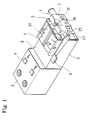
- Fig. 1 shows a main body 1. This carries in his rear part of a control housing 2 in which the control electronics and at least one actuating element 9 are placed.
- the main body 1 includes a frame that Push rods 28 is stored at the front ends 27 Exchange holder 10 is attached, either with a Chuck 3 or equipped with an adapter 12 (Fig.2) and serves to accommodate an optical fiber.
- swiveling Heating jaws 4 with actuating handles 51 are also shown like stripping knife jaws 5 and a clamping force setting rosette for the jaws 36 by spring force be held in the closed position and by a Release lever 6 with a right-left steep thread on one Shaft 47 of the lever 6 for the insertion of an optical fiber can be opened.
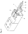
- Fig. 2 shows the same structure, but in place of Clamping head the adapter 12, the mounting bracket 11 carries, in which a multi-core fiber optic cable 45 is inserted is.
- a position stop 13 determines the relative axial position of the mounting bracket 11 on the adapter 12.
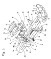
- FIG. 3 shows an example of an internal structure, one according to the invention Embodiment with one with Main body connectable motor bracket 31 and an attached thereto electric drive 29, which if necessary as Gear motor is formed.
- This drives a threaded spindle 32, which drives a thrust element 33.
- the thrust element 33 slides in the area of exemptions 34 on the Push rods 28.
- the exemptions 34 are limited by Stop rings 50 or shoulders 44. Shoulders 44 and stop rings 50 could also be interchanged.
- the Rings serve as shoulders, but are for assembly purposes removable. As soon as the thrust element 33 on the shoulders 44 or rings 50 is present, it takes on its forward or Backward movement with the push rods 28.
- a further push rod 35 slidably placed by a brake block 20 easily is braked in the axial direction and is thereby carried along.
- a Notch or groove 30 on the other push rod 35 transmits this axial movement on a fork 15 of a backdrop 16.
- the backdrop 16 engages with positive elements in oblique grooves 18 a backdrop 17, preferably as a printed circuit board is trained.
- These printed circuit boards each carry two heated baking fork 19 for fastening the heating jaws 4.
- the Heating jaw forks 19 are electrically conductive and provide one appropriate power supply for the heating elements of the heating jaws 4.
- In the lower region of the thrust element 33 are two resilient pressure pins or ball snapper 21 placed.
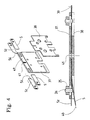
- Fig. 4 shows a precise guidance of the knives 5 and centering jaws 5z and the simple interchangeability of the same by slight bending 40 and locking or unlocking on the cylinder pins 26 without tools required are.
- the pusher element is in the starting or resting position 33 (Fig. 3) on the far left and thus also the push rods 28 and the clamping head 3 in retracted Rest.
- the knives 5 or centering jaws 5z over the Lever 25 by swiveling about its fixed axes of rotation 23 and the heating jaws 4 opened over the scenes 16 and 24.
- the drive 29 moves by rotating the threaded spindle 31, the thrust element 33 right. Due to the slight braking effect between others Push rod 35 and brake block 20 also this and thus pushed the backdrop 16 over the fork 15 to the right. Through oblique grooves 18 into which the positive elements protrude of the backdrop 16, the backdrops or Printed circuit boards 17 and thus the heating jaw forks 19 and finally the heating jaws 4 on the conductor to be machined moved together.
- the electronic control stops the Drive 29 before the thrust element 33, the shoulders 44 of the Push rods has reached 28.
- the control is now waiting the expiry of the set heating time of the heating jaws 4.
- the drive pushes by turning the Threaded spindle 32, the thrust element 33 further to the right.
- that of the desired one Take-off speed corresponds.
- the other push rod 33 slips through the brake block 20, since the heating jaws 4 no longer close to let.
- the friction force that occurs is proportional the contact pressure the heating jaws 4 to the conductor.
- the backdrop 24 can no longer be pushed further to the right as they are no more Has exemption for the lever 25.
- the ball snapper therefore snap out of the left locking grooves 22 and slide forward along the side edge of the backdrop 24 until it engage in the front locking grooves 22.
- the electronic control switches the electronic control to change the direction of motor rotation and that Thrust element 33 moves in the area of the exemption 34 back without transporting the push rods 28.
- Due to the locking of the ball snapper 21 in the locking grooves 22 also becomes the backdrop 24 withdrawn, thereby pivoting the lever 25 in the opening direction and the knives 5 and centering jaws 5z opened.
- Push rods 28 strikes, the electronics stops the drive. Only after removing the stripped conductor the drive moves with the push element and the push rods 28 and with the clamping head 3 with preferably increased speed back to the original left rest position. This can be done by pressing a "Return” button can be brought about or with a certain There is a time delay. Switch buttons are also conceivable that perform both functions at the same time.
- the invention also includes of optical fibers also one for cables in the conventional sense, or you can also benefit can be used for conventional cables.
Landscapes
- Physics & Mathematics (AREA)
- General Physics & Mathematics (AREA)
- Optics & Photonics (AREA)
- Light Guides In General And Applications Therefor (AREA)
- Mechanical Coupling Of Light Guides (AREA)
Applications Claiming Priority (3)
| Application Number | Priority Date | Filing Date | Title |
|---|---|---|---|
| CH15097 | 1997-01-24 | ||
| CH15097 | 1997-01-24 | ||
| PCT/EP1998/000406 WO1998033082A1 (de) | 1997-01-24 | 1998-01-26 | Vorrichtung zum entfernen von schichten an lichtwellenleitern |
Publications (2)
| Publication Number | Publication Date |
|---|---|
| EP0954762A1 EP0954762A1 (de) | 1999-11-10 |
| EP0954762B1 true EP0954762B1 (de) | 2004-08-18 |
Family
ID=4180396
Family Applications (1)
| Application Number | Title | Priority Date | Filing Date |
|---|---|---|---|
| EP98905349A Expired - Lifetime EP0954762B1 (de) | 1997-01-24 | 1998-01-26 | Vorrichtung zum entfernen von schichten an lichtwellenleitern |
Country Status (5)
| Country | Link |
|---|---|
| US (1) | US6321621B1 (enExample) |
| EP (1) | EP0954762B1 (enExample) |
| JP (1) | JP4018155B2 (enExample) |
| DE (1) | DE59811835D1 (enExample) |
| WO (1) | WO1998033082A1 (enExample) |
Families Citing this family (18)
| Publication number | Priority date | Publication date | Assignee | Title |
|---|---|---|---|---|
| SE513172C2 (sv) * | 1998-07-03 | 2000-07-24 | Ericsson Telefon Ab L M | Förfarande och anordning för att avlägsna polymerbeläggning från en optisk fiber |
| GB9902731D0 (en) * | 1999-02-09 | 1999-03-31 | Gkn Westland Helicopters Ltd | Cable handling apparatus |
| DE10113740A1 (de) | 2001-03-21 | 2002-07-18 | Agilent Technologies Inc | Vorrichtung zum Bearbeiten einer isolierten optischen Faser |
| WO2002084352A1 (de) * | 2001-04-11 | 2002-10-24 | Schleuniger Holding Ag | Glasfaserabisoliervorrichtung |
| JP2002328241A (ja) * | 2001-04-26 | 2002-11-15 | Fujikura Ltd | 光ファイバ被覆除去装置 |
| JP4535219B2 (ja) * | 2001-06-12 | 2010-09-01 | 住友電気工業株式会社 | 光ファイバ被覆除去装置 |
| KR100471083B1 (ko) * | 2002-12-24 | 2005-03-10 | 삼성전자주식회사 | 광섬유 절단장치 |
| KR20070114299A (ko) | 2005-03-25 | 2007-11-30 | 쉴로이니게르 홀딩 아게 | 제거 장치용 회전식 제거 헤드 |
| DE102007001707A1 (de) * | 2007-01-11 | 2008-07-17 | CCS Technology, Inc., Wilmington | Thermische Absetzgerätvorrichtung |
| JP2010530727A (ja) * | 2007-06-13 | 2010-09-09 | シュロニガー ホールディング アーゲー | ワイヤストリッパ用のセンタリング装置 |
| US7681476B2 (en) | 2007-07-31 | 2010-03-23 | Adc Telecommunications, Inc. | Fiber optic cable stripper |
| US8640329B2 (en) * | 2008-09-03 | 2014-02-04 | Adc Telecommunications, Inc. | Hybrid fiber/copper cable preparation tool |
| CN101989734B (zh) * | 2010-08-09 | 2012-08-15 | 苏州百狮腾电气有限公司 | 剥线设备 |
| US9453964B2 (en) * | 2013-02-28 | 2016-09-27 | Corning Optical Communications LLC | Stripping apparatus and methods for optical fibers |
| USD745905S1 (en) * | 2013-10-11 | 2015-12-22 | Dh Infotech (Weihai) Inc. | Fiber thermal stripping device |
| US10180540B2 (en) | 2014-12-15 | 2019-01-15 | CommScope Connectivity Belgium BVBA | Optical fiber clamping assembly having a plurality of cable clamp arms |
| KR102325125B1 (ko) * | 2019-08-28 | 2021-11-12 | 유씨엘스위프트(주) | 피복 두께가 다른 이경 광섬유의 피복 탈피기 |
| US11513290B2 (en) | 2019-08-30 | 2022-11-29 | Commscope Technologies Llc | Strip stop mechanism using rotating lever as a positioning stop |
Family Cites Families (16)
| Publication number | Priority date | Publication date | Assignee | Title |
|---|---|---|---|---|
| US3182532A (en) * | 1962-10-01 | 1965-05-11 | Ideal Ind | Pistol grip wire stripper |
| US5351580A (en) * | 1983-08-17 | 1994-10-04 | Milbar Corporation | Electrically heated wire stripping device |
| US4601093A (en) * | 1984-09-21 | 1986-07-22 | Eubanks Engineering Co. | Wire insulation stripping apparatus |
| US4619164A (en) | 1984-12-10 | 1986-10-28 | E. I. Du Pont De Nemours And Company | Orbital stripping device |
| DE3661165D1 (en) * | 1985-02-22 | 1988-12-15 | Jiri Stepan | Stripping device |
| US4584912A (en) * | 1985-05-06 | 1986-04-29 | Artos Engineering Company | Wire feeding, cutting and stripping apparatus having clutch-operated feed and cam-operated cutter/stripper |
| US4850108A (en) | 1987-09-17 | 1989-07-25 | Micro Electronics, Inc. | Stripping device |
| DE3906520A1 (de) * | 1989-02-27 | 1990-09-06 | Siemens Ag | Vorrichtung zum konfektionieren von lichtwellenleiterenden mit verbindern |
| US5016500A (en) * | 1990-04-10 | 1991-05-21 | Teledyne Kinetics | Battery powered temperature-controlled wire stripper |
| JPH04257802A (ja) * | 1991-02-13 | 1992-09-14 | Furukawa Electric Co Ltd:The | 光ケーブルの自動端末処理装置 |
| CH683645A5 (de) * | 1991-11-12 | 1994-04-15 | Jiri Stepan | Abisoliervorrichtung für Glasfaserkabel. |
| DE4203995A1 (de) * | 1992-02-12 | 1993-08-19 | Philips Patentverwaltung | Verfahren und vorrichtung zum abloesen einer beschichtung von einem lichtwellenleiter |
| US5582078A (en) * | 1992-05-18 | 1996-12-10 | Eubanks Engineering Company | Wire displacing and stripping apparatus and method |
| US5398573A (en) * | 1992-06-24 | 1995-03-21 | Artos Engineering Company | Adjustable wire cutting and stripping apparatus |
| US5320002A (en) * | 1992-10-01 | 1994-06-14 | The Boeing Company | Machine for stripping outer jacket from multi-conductor cables |
| US5669276A (en) * | 1996-06-04 | 1997-09-23 | Spacek; Timothy | Apparatus for cable stripping |
-
1998
- 1998-01-26 US US09/355,054 patent/US6321621B1/en not_active Expired - Lifetime
- 1998-01-26 EP EP98905349A patent/EP0954762B1/de not_active Expired - Lifetime
- 1998-01-26 DE DE59811835T patent/DE59811835D1/de not_active Expired - Fee Related
- 1998-01-26 WO PCT/EP1998/000406 patent/WO1998033082A1/de not_active Ceased
- 1998-01-26 JP JP53160598A patent/JP4018155B2/ja not_active Expired - Fee Related
Also Published As
| Publication number | Publication date |
|---|---|
| DE59811835D1 (de) | 2004-09-23 |
| JP2001511262A (ja) | 2001-08-07 |
| EP0954762A1 (de) | 1999-11-10 |
| JP4018155B2 (ja) | 2007-12-05 |
| US6321621B1 (en) | 2001-11-27 |
| WO1998033082A1 (de) | 1998-07-30 |
Similar Documents
| Publication | Publication Date | Title |
|---|---|---|
| EP0954762B1 (de) | Vorrichtung zum entfernen von schichten an lichtwellenleitern | |
| CH683645A5 (de) | Abisoliervorrichtung für Glasfaserkabel. | |
| DE3328052A1 (de) | Montagegeraet fuer mehrfachverbinder fuer lichtwellenleiter | |
| DE1067492B (de) | Werkzeug zum Vorbereiten und Aufbringen eines Drahtes auf eine Klemme | |
| EP3163696A1 (de) | Abisolierkopf und verfahren zu dessen betrieb | |
| DE2818018C2 (enExample) | ||
| DE69023798T2 (de) | Halterung für eine Vorrichtung zur Bearbeitung des Endes einer optischen Faser. | |
| DE102007019386B4 (de) | Abmantelwerkzeug | |
| WO2008015261A1 (de) | VORRICHTUNG ZUM SPLEIßEN VON LICHTWELLENLEITERABSCHNITTEN | |
| DE3781614T2 (de) | Kabelabmantelungswerkzeug. | |
| EP1356326B1 (de) | Zangenartiges werkzeug und verfahren zum durchtrennen von lichtwellenleiterkabeln | |
| DE60018625T2 (de) | Vorrichtung zur Wärmezufuhr an einen Kleber | |
| EP0430868A1 (de) | Verfahren und Vorrichtung zum Abisolieren der Endabschnitte optischer Kabel | |
| DE2930612A1 (de) | Verfahren und vorrichtung zum abisolieren von elektrischen leitern bzw. abmanteln von elektrischen kabeln | |
| DE202008017576U1 (de) | Bearbeitungsmodul für eine Kabelabisoliervorrichtung | |
| DE20007821U1 (de) | Modelliervorrichtung | |
| WO2008084078A1 (de) | Thermische absetzgerätvorrichtung | |
| DE10212993B4 (de) | Crimp-Verfahren | |
| DE2817727C3 (de) | Halbautomatische Vorrichtung zum Abisolieren der Enden von Leitern mit Isolationseinschneidmessern | |
| DE102010023786B4 (de) | Handwerkzeug, insbesondere elektrisch betriebenes Abisolier- und Crimphandwerkzeug | |
| EP1042850B1 (de) | Abisoliervorrichtung | |
| DE4234060A1 (de) | Vorrichtung zur Entmantelung elektrischer Kabel | |
| DE19806995A1 (de) | Verfahren und Vorrichtung zum Verbinden von Gegenständen mittels Flechtdrahtes | |
| DE3436668A1 (de) | Verfahren und vorrichtung zum entfernen der primaerbeschichtung einer lichtwellenleiterfaser | |
| DE19858474A1 (de) | Verfahren zum Herstellen von Stirnflächen an Lichtwellenleitern aus optischen Fasern aus Kunststoff (POF) und Vorrichtung zur Durchführung des Verfahrens |
Legal Events
| Date | Code | Title | Description |
|---|---|---|---|
| PUAI | Public reference made under article 153(3) epc to a published international application that has entered the european phase |
Free format text: ORIGINAL CODE: 0009012 |
|
| 17P | Request for examination filed |
Effective date: 19990824 |
|
| AK | Designated contracting states |
Kind code of ref document: A1 Designated state(s): CH DE IT LI SE |
|
| 17Q | First examination report despatched |
Effective date: 20010509 |
|
| GRAP | Despatch of communication of intention to grant a patent |
Free format text: ORIGINAL CODE: EPIDOSNIGR1 |
|
| GRAS | Grant fee paid |
Free format text: ORIGINAL CODE: EPIDOSNIGR3 |
|
| GRAA | (expected) grant |
Free format text: ORIGINAL CODE: 0009210 |
|
| AK | Designated contracting states |
Kind code of ref document: B1 Designated state(s): CH DE IT LI SE |
|
| PG25 | Lapsed in a contracting state [announced via postgrant information from national office to epo] |
Ref country code: IT Free format text: LAPSE BECAUSE OF FAILURE TO SUBMIT A TRANSLATION OF THE DESCRIPTION OR TO PAY THE FEE WITHIN THE PRE;WARNING: LAPSES OF ITALIAN PATENTS WITH EFFECTIVE DATE BEFORE 2007 MAY HAVE OCCURRED AT ANY TIME BEFORE 2007. THE CORRECT EFFECTIVE DATE MAY BE DIFFERENT FROM THE ONE RECORDED.SCRIBED TIME-LIMIT Effective date: 20040818 |
|
| REG | Reference to a national code |
Ref country code: CH Ref legal event code: EP |
|
| REF | Corresponds to: |
Ref document number: 59811835 Country of ref document: DE Date of ref document: 20040923 Kind code of ref document: P |
|
| REG | Reference to a national code |
Ref country code: CH Ref legal event code: NV Representative=s name: ROSENICH PAUL; GISLER CHRISTIAN PATENTBUERO PAUL R |
|
| PG25 | Lapsed in a contracting state [announced via postgrant information from national office to epo] |
Ref country code: SE Free format text: LAPSE BECAUSE OF FAILURE TO SUBMIT A TRANSLATION OF THE DESCRIPTION OR TO PAY THE FEE WITHIN THE PRESCRIBED TIME-LIMIT Effective date: 20041118 |
|
| PGFP | Annual fee paid to national office [announced via postgrant information from national office to epo] |
Ref country code: CH Payment date: 20050120 Year of fee payment: 8 |
|
| PLBE | No opposition filed within time limit |
Free format text: ORIGINAL CODE: 0009261 |
|
| STAA | Information on the status of an ep patent application or granted ep patent |
Free format text: STATUS: NO OPPOSITION FILED WITHIN TIME LIMIT |
|
| 26N | No opposition filed |
Effective date: 20050519 |
|
| PG25 | Lapsed in a contracting state [announced via postgrant information from national office to epo] |
Ref country code: LI Free format text: LAPSE BECAUSE OF NON-PAYMENT OF DUE FEES Effective date: 20060131 Ref country code: CH Free format text: LAPSE BECAUSE OF NON-PAYMENT OF DUE FEES Effective date: 20060131 |
|
| PGFP | Annual fee paid to national office [announced via postgrant information from national office to epo] |
Ref country code: DE Payment date: 20060505 Year of fee payment: 9 |
|
| REG | Reference to a national code |
Ref country code: CH Ref legal event code: PL |
|
| PG25 | Lapsed in a contracting state [announced via postgrant information from national office to epo] |
Ref country code: DE Free format text: LAPSE BECAUSE OF NON-PAYMENT OF DUE FEES Effective date: 20070801 |