EP0952031A2 - Neigungsverstellvorrichtung für Sitze - Google Patents
Neigungsverstellvorrichtung für Sitze Download PDFInfo
- Publication number
- EP0952031A2 EP0952031A2 EP99107177A EP99107177A EP0952031A2 EP 0952031 A2 EP0952031 A2 EP 0952031A2 EP 99107177 A EP99107177 A EP 99107177A EP 99107177 A EP99107177 A EP 99107177A EP 0952031 A2 EP0952031 A2 EP 0952031A2
- Authority
- EP
- European Patent Office
- Prior art keywords
- tooth
- base plate
- teeth
- plate
- reclining device
- Prior art date
- Legal status (The legal status is an assumption and is not a legal conclusion. Google has not performed a legal analysis and makes no representation as to the accuracy of the status listed.)
- Granted
Links
Images


Classifications
-
- B—PERFORMING OPERATIONS; TRANSPORTING
- B60—VEHICLES IN GENERAL
- B60N—SEATS SPECIALLY ADAPTED FOR VEHICLES; VEHICLE PASSENGER ACCOMMODATION NOT OTHERWISE PROVIDED FOR
- B60N2/00—Seats specially adapted for vehicles; Arrangement or mounting of seats in vehicles
- B60N2/02—Seats specially adapted for vehicles; Arrangement or mounting of seats in vehicles the seat or part thereof being movable, e.g. adjustable
- B60N2/22—Seats specially adapted for vehicles; Arrangement or mounting of seats in vehicles the seat or part thereof being movable, e.g. adjustable the back-rest being adjustable
- B60N2/235—Seats specially adapted for vehicles; Arrangement or mounting of seats in vehicles the seat or part thereof being movable, e.g. adjustable the back-rest being adjustable by gear-pawl type mechanisms
- B60N2/2356—Seats specially adapted for vehicles; Arrangement or mounting of seats in vehicles the seat or part thereof being movable, e.g. adjustable the back-rest being adjustable by gear-pawl type mechanisms with internal pawls
- B60N2/236—Seats specially adapted for vehicles; Arrangement or mounting of seats in vehicles the seat or part thereof being movable, e.g. adjustable the back-rest being adjustable by gear-pawl type mechanisms with internal pawls linearly movable
-
- B—PERFORMING OPERATIONS; TRANSPORTING
- B60—VEHICLES IN GENERAL
- B60N—SEATS SPECIALLY ADAPTED FOR VEHICLES; VEHICLE PASSENGER ACCOMMODATION NOT OTHERWISE PROVIDED FOR
- B60N2205/00—General mechanical or structural details
- B60N2205/20—Measures for elimination or compensation of play or backlash
Definitions
- the present invention relates to seat reclining devices and more particularly to automotive seat reclining devices of a type which employs toothed elements for locking a seatback at a desired angular position relative to a seat cushion.
- a seat reclining device which comprises a base plate adapted to be secured to a seat cushion; a tooth plate adapted to be secured to a seatback; a center shaft for permitting the tooth plate to pivot relative to the base plate; first teeth possessed by the tooth plate; a tooth piece having second teeth which are engageable with the first teeth to bring about a locked condition between the base plate and the tooth plate, the tooth piece having parallel side walls; and a guide groove defined by the base plate for slidably receiving therein the tooth piece, the guide groove having parallel guide walls which face and contact the parallel side walls of the tooth piece respectively, wherein at least one of the parallel guide walls is provided with a projection which is projected in a direction to reduce a width of the guide groove.
- a seat reclining device which comprises a base plate adapted to be secured to a seat cushion; a tooth plate adapted to be secured to a seatback; a center shaft for permitting the tooth plate to pivot relative to the base plate; first teeth possessed by the tooth plate; a tooth piece having second teeth which are engageable with the first teeth to establish a locked condition between the base plate and the tooth plate, the tooth piece having parallel side walls; a guide groove defined by the base plate for slidably receiving therein the tooth piece, the guide groove having parallel guide walls which face and contact the parallel side walls of the tooth piece respectively; a cam member pivotally supported by the center shaft, the cam member moving the tooth piece in a direction to establish the engagement between the first and second teeth when pivoted in a first direction and moving the tooth piece in a direction to cancel the engagement between the first and second teeth when pivoted in a second direction; and a control lever pivotally supported by the center shaft and rotated together with the cam member, wherein the parallel guide walls are
- first and second embodiments 100 and 200 of the present invention will be described in detail with reference to the accompanying drawings. Since the first and second embodiments are similar in construction to each other, description on one embodiment will be made with the aid of the other embodiment.
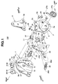
- FIG. 1 there is shown in an exploded manner a seat reclining device 100 which is a first embodiment of the present invention.
- denoted by numeral 1 is a base plate which is secured to a rear left side of a seat cushion (102, see Fig. 2).
- a tooth plate 3 is pivotally connected to the base plate 1 through a center shaft 2.
- each pin 8a or 8b is caulked.
- the arm member 5 is secured to a lower left side of a seatback (104, see Fig. 2).
- the base plate 1, the center shaft 2, the tooth plate 3 and the arm 5 constitute a left-side pivot mechanism by which the seatback 104 is pivotal relative to the seat cushion 102.
- a right-side pivot mechanism similar to the above-mentioned left-side one is installed at a rear right side of the seat cushion 102. That is, the seatback 104 is pivotally connected to the seat cushion 102 through the left-side and right-side pivot mechanisms.
- the base plate 1 is formed with a round upper edge 1a which is concentric with an axis of the center shaft 2.
- the tooth plate 3 is formed, on a surface facing the base plate 1, with a generally sectoral recess 6.
- An upper arcuate wall of the recess 6 is shaped concentric with the axis of the center shaft 2 and formed with teeth 7 (viz., first teeth). These teeth 7 may be provided by a press working or the like.
- a sliding holder 9 is employed which is connected to an upper portion of the tooth plate 3.
- the above-mentioned two pins 8a and 8b and another pin 80, the above-mentioned two openings 4a and 4b of the tooth plate 3 and another opening 4c of the same, and three openings 9b, 9b and 9c formed in the sliding holder 9 are employed. That is, each pin 8a, 8b or 80 passing through the aligned openings of the tooth plate 3 and the sliding shoe 9 is caulked for the connection between the tooth plate 3, the arm member 5 and the sliding holder 9. That is, the these three parts 3, 5 and 9 can pivot about the axis of the center shaft 2 like a single unit.
- the sliding holder 9 has an arcuate track 9a which is slidably mated with the round upper edge 1a of the base plate 1, so that upon pivoting of the tooth plate 3 relative to the base plate 1, the track 9a of the sliding holder 9 slides on and along the round upper edge 1a of the base plate 1 while preventing separation of the tooth plate 3 from the base plate 1. That is, due to provision of the sliding holder 9, a stable and smoothed pivoting of the tooth plate 3 relative to the base plate 1 is achieved.
- a tooth piece 11 is partially and movably received in the sectoral recess 6 of the tooth plate 3. That is, the thickness of the tooth piece 11 is somewhat greater than the depth of the sectoral recess 6.
- the tooth piece 11 is formed at its upper round edge with teeth 10 (second teeth) which are operatively engageable with the teeth 7 of the tooth plate 3.
- the tooth piece 11 has two parallel side walls 14a and 14b and a lateral projection 15.
- the base plate 1 is formed with a recess 1b in which the projected part of the tooth piece 11 is slidably received.
- a radially extending guide groove 12 for the tooth piece 11 is provided by the base plate 1, which is merged with the recess 1b and has two parallel guide walls 13a and 13b. That is, for the guided movement of the tooth piece 11 by the guide groove 12, the parallel side walls 14a and 14b of the tooth piece 11 slidably contact the parallel guide walls 13a and 13b of the guide groove 12 respectively.
- Denoted by numerals 47 and 48 are portions pressed by a punching machine or the like for adjusting the distance between given portions 49 and 50 of the guide walls 13a and 13b, which will be described in detail hereinafter.
- a cam member 19 is put between the tooth member 3 and the base plate 1 and rotatably disposed about the center shaft 2.
- the cam member 19 comprises a pushing arm 20 which is contactable with a lower wall of the tooth piece 11 and a drawing pawl 21 which is engageable with the lateral projection 15 of the tooth piece 11.
- the center shaft 2 comprises a right end portion 2a which has a non-circular cross section, a larger diameter bearing portion 2b which rotatably carries thereon both an after-mentioned control lever 23 and the cam member 19, a smaller diameter bearing portion 2c which rotatably carries thereon the tooth plate 3, and a left end portion 2d which has an axially extending slit 2e.
- a flange 22 is provided between the right end portion 2a and the larger diameter bearing portion 2b.
- the right end portion 2a of the center shaft 2 is tightly fitted in a non-circular opening 1c formed in the base plate 1.
- Caulking technique may be used to secure the center shaft 2 to the base plate 1.
- the flange 22 severs as a stopper for suppressing excessive insertion of the center shaft 2 into the opening 1c.
- the larger diameter bearing portion 2b is received in both an opening 23a formed in the control lever 23 and an opening 19a formed in the cam member 19, so that the control lever 23 and the cam member 19 can pivot about the axis of the center shaft 2.
- the smaller diameter bearing portion 2c is received in an opening 3a formed in the tooth plate 3, so that also the tooth plate 3 can pivot about the axis of the center shaft 2.
- the left end portion 2d of the center shaft 2 projected from the opening 3a catches an inner end 27a of a return spring 27 by the slit 2e.
- An outer end 27b of the return spring 27 is hooked to a pin 28 fixed to the tooth plate 3. Due to work of the return spring 27, the tooth plate 3 and thus the seatback 104 (see Fig. 2) are constantly biased to pivot forward, that is, in a counterclockwise direction in Fig. 1 about the axis of the center shaft 2.
- the control lever 23 has a grip 35 and has near the opening 23a a small projection 33 which is fitted in an opening 34 formed in the cam member 19.
- the control lever 23 and the cam member 19 pivot about the center shaft 2 like a single unit.
- the control lever 23 further has another projection 23b to which one end 36a of a spring 36 is hooked.
- the other end 36b of the spring 36 is hooked to a pin 37 fixed to the base plate 1.
- a tooth member guiding arrangement that is, the arrangement for guiding the tooth piece 11 in and along the guide groove 12 of the base plate 1 will be described in detail with reference to Figs. 4 and 5.
- the projections 49 and 50 are provided by pressing given portions 47 and 48 of the base plate 1 by using a punching machine or the like. More specifically, the punching to the given portions 47 and 48 is carried out with the tooth piece 11 being kept engaged with the teeth 7 of the tooth plate 3. If desired, in place of the tooth piece 11 actually used, an imitation member (or tool) having the same size and structure as the tooth piece 11 may be used at the time when the given portions 47 and 48 are being punched.
- two guiding zones are positively provided at each side of the guide groove 12, one being a tight-zone where the side wall 14a or 14b of the tooth piece 11 intimately contacts the guide wall 13a or 13b of the guide groove 12, and the other being a gentle-zone where the side wall 14a or 14b of the tooth piece 11 is separated from the guide wall 13a or 13b of the guide groove 12 by a degree "S".
- one projection may be provided on either one of guide walls 13a and 13b.
- two or more projections may be provided on each guide wall 13a or 13b.
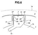
- Fig. 6 shows a modification of the tooth member guiding arrangement which assures not only the above-mentioned advantage but also a smoothed movement of the tooth piece 11 in the guide groove 12. That is, in this modification, elongate areas 47' and 48' of the base plate 1 are pressed or punched to provide the guide walls 13a and 13b with longer projections 49' and 50'. Due to increase of the contacting area between the tooth member 11 and each of the guide wall 13a or 13b, the movement of the tooth member 11 in the guide groove 12 is stably and smoothly made. Furthermore, the mechanical strength of the projections 49' and 50' is increased.
- each groove provided as a result of punching the elongate area 47' or 48' may have a V-shaped cross section or a semicircular cross section. That is, the shape of the groove varies depending on the shape of the work head of the punching tool.
- the seat reclining device 100 assumes a locked condition. That is, due to the work of the spring 36, the pushing arm 20 of the cam member 19 keeps pushing the tooth piece 11 against the teeth 7 of the tooth plate 3, and thus, the tooth plate 3 is kept locked to the base plate 1. That is, the seatback 104 is locked to the seat cushion 102 while assuming the certain angular position. Furthermore, due to the work of the spring 36, the control lever 23 assumes its lower position, that is, a rest position.
- the seatback 104 Upon taking this unlocked condition, the seatback 104 is automatically pivoted forward due to the force of the return spring 27. The seatback 104 is then manually pivoted backward against the force of the return spring 27.
- the control lever 23 is released.
- the drawing pawl 21 of the cam member 19 is disengaged from the lateral projection 15 of the tooth piece 11 while bringing the pushing arm 20 of the cam member 19 into abutment with the lower wall of the tooth piece 11.
- the tooth piece 11 becomes engaged with the teeth 7 of the tooth plate 3 at a new angular position, permitting the seatback 104 to be locked at the new desired angular position.
- the tooth piece 11 is slid upward in the guide groove 12.
- FIG. 2 and 3 there is shown a seat reclining device 200 which is a second embodiment of the present invention.
- flanged pins 38a and 38b are used in place of the pins 8a, 8b, 80 and the sliding shoe 9 which are employed in the first embodiment 100. That is, the pins 38a and 38b extending from the tooth plate 3 have each a circular flange 38a' or 38b' which is slidably mated with the round upper edge 1a of the base plate 1. With such flanged pins 38a and 38b, undesired separation of the tooth plate 3 from the base plate 1 is prevented and thus stable pivoting of the tooth plate 3 relative to the base plate 1 is assured.
- Denoted by numeral 44 in Fig. 2 is a lug formed on the base plate 1 to hold one end of the spring 36.
- a mechanism for transmitting movement of the control lever 23 to a corresponding part of the right-side pivot mechanism (not shown) is employed. That is, as is seen from Fig. 2, the control lever 23 is formed with an arm portion 39 to which an actuating pin 40 is fixed. The actuating pin 40 extends toward the other side in Fig. 2 through an arcuate slot 43 formed in the base plate 1. The arcuate slot 43 is concentric with the center shaft 2.
- a generally V-shaped lever 41 is pivotally connected through a pivot pin 42 to a back surface of the base plate 1. The lever 41 and the pivot pin 42 are secured to each other to move like a single unit. The lever 41 puts the actuating pin 40 between the forks thereof, as shown.
- a tubular transmission shaft 45 is coaxially secured to the pivot pin 42, which extends to the right-side pivot mechanism (not shown).
- the actuating pin 40 fixed to the control lever 23 is brought into abutment with one of the forks of the V-shaped lever 41 to pivot the lever 41 about an axis of the pivot pin 42 in a so-called disengaging direction, that is, in a counterclockwise direction in Fig. 2. Due to the integral connection between the V-shaped lever 41, the pivot pin 42 and the transmission shaft 45, the pivoting of the lever 41 is transmitted through the transmission shaft 45 to a corresponding part of the right-side pivot mechanism for establishing an unlocked condition of the same.
- the locked and unlocked conditions of the left-side and right-side pivot mechanisms are synchronously carried out.
Landscapes
- Engineering & Computer Science (AREA)
- Aviation & Aerospace Engineering (AREA)
- Transportation (AREA)
- Mechanical Engineering (AREA)
- Chairs For Special Purposes, Such As Reclining Chairs (AREA)
- Seats For Vehicles (AREA)
Applications Claiming Priority (2)
| Application Number | Priority Date | Filing Date | Title |
|---|---|---|---|
| JP11026698 | 1998-04-21 | ||
| JP10110266A JPH11299563A (ja) | 1998-04-21 | 1998-04-21 | 自動車用シートリクライニング装置のガタ防止方法及びその構造 |
Publications (3)
| Publication Number | Publication Date |
|---|---|
| EP0952031A2 true EP0952031A2 (de) | 1999-10-27 |
| EP0952031A3 EP0952031A3 (de) | 2001-08-16 |
| EP0952031B1 EP0952031B1 (de) | 2004-08-18 |
Family
ID=14531339
Family Applications (1)
| Application Number | Title | Priority Date | Filing Date |
|---|---|---|---|
| EP99107177A Expired - Lifetime EP0952031B1 (de) | 1998-04-21 | 1999-04-13 | Neigungsverstellvorrichtung für Sitze |
Country Status (4)
| Country | Link |
|---|---|
| US (1) | US6220666B1 (de) |
| EP (1) | EP0952031B1 (de) |
| JP (1) | JPH11299563A (de) |
| DE (1) | DE69919435T2 (de) |
Cited By (2)
| Publication number | Priority date | Publication date | Assignee | Title |
|---|---|---|---|---|
| FR2848927A1 (fr) * | 2002-10-31 | 2004-06-25 | Araco Kk | Procedes et appareil pour ajuster un jeu |
| WO2004103764A1 (en) * | 2004-01-07 | 2004-12-02 | Ifb Automotive Private Limited | Twin recliner for automotive seats |
Families Citing this family (16)
| Publication number | Priority date | Publication date | Assignee | Title |
|---|---|---|---|---|
| DE10019854C5 (de) * | 2000-04-20 | 2004-06-03 | Keiper Gmbh & Co. Kg | Manueller Hebelantrieb für Stellvorrichtungen an Sitzen, insbesondere an Kraftfahrzeugsitzen |
| JP3979132B2 (ja) | 2002-03-13 | 2007-09-19 | トヨタ紡織株式会社 | リクライニング装置における摺動隙間の設定方法 |
| JP3991780B2 (ja) * | 2002-06-19 | 2007-10-17 | アイシン精機株式会社 | シートリクライニング装置 |
| JP4185750B2 (ja) * | 2002-10-01 | 2008-11-26 | 富士機工株式会社 | 車両用シートリクライニング装置 |
| US6854802B2 (en) * | 2002-10-01 | 2005-02-15 | Fujikiko Kabushiki Kaisha | Seat recliner for vehicle |
| DE10253054B4 (de) * | 2002-11-14 | 2007-01-18 | Keiper Gmbh & Co.Kg | Beschlag für einen Fahrzeugsitz |
| US6910738B2 (en) | 2003-01-28 | 2005-06-28 | Fisher Dynamics Corporation | Device and method for assembling a recliner mechanism |
| US6890034B2 (en) | 2003-01-28 | 2005-05-10 | Fisher Dynamics Corporation | Compact recliner with locking cams |
| JP4806909B2 (ja) * | 2003-08-22 | 2011-11-02 | トヨタ紡織株式会社 | リクライニング装置 |
| JP2005177310A (ja) * | 2003-12-22 | 2005-07-07 | Delta Kogyo Co Ltd | シートのリクライニング装置 |
| US7025422B2 (en) * | 2004-03-11 | 2006-04-11 | Fisher Dynamics Corporation | Round recliner assembly with rear folding latch |
| US7097253B2 (en) * | 2004-03-11 | 2006-08-29 | Fisher Dynamics Corporation | Round recliner assembly with rear folding latch |
| JP5060201B2 (ja) * | 2007-08-09 | 2012-10-31 | 株式会社今仙電機製作所 | リクライニング装置 |
| JP5176479B2 (ja) * | 2007-10-23 | 2013-04-03 | トヨタ紡織株式会社 | 車両用シートのリクライニング装置 |
| WO2012103443A1 (en) * | 2011-01-28 | 2012-08-02 | Johnson Controls Technology Company | Manual lever recliner evolution |
| DE102011108976B4 (de) * | 2011-07-26 | 2015-03-12 | Johnson Controls Components Gmbh & Co. Kg | Verfahren zur Herstellung einer Lageranordnung und Beschlag für einen Fahrzeugsitz mit einer hiernach hergestellten Lageranordnung |
Citations (1)
| Publication number | Priority date | Publication date | Assignee | Title |
|---|---|---|---|---|
| JPH10110266A (ja) | 1996-10-04 | 1998-04-28 | Dowa Mining Co Ltd | スパッタリングターゲットとその接合方法 |
Family Cites Families (17)
| Publication number | Priority date | Publication date | Assignee | Title |
|---|---|---|---|---|
| FR2191422A6 (de) * | 1972-07-03 | 1974-02-01 | Faure Bertrand Ets | |
| FR2594022B1 (fr) * | 1986-02-07 | 1988-05-27 | Cousin Cie Ets A & M Freres | Articulation pour dossier de siege a grain composite. |
| FR2599684B1 (fr) * | 1986-06-06 | 1990-02-02 | Cousin Cie Ets A & M Freres | Articulations pour dossier de siege de vehicule ou applications analogues comportant des grains a guidages asymetriques |
| US4785379A (en) * | 1987-12-04 | 1988-11-15 | Gte Government Systems Corporation | Printed circuit module retainer |
| US5622407A (en) * | 1993-11-19 | 1997-04-22 | Aisin Seiki Kabushiki Kaisha | Seat apparatus |
| JP3509150B2 (ja) * | 1993-11-19 | 2004-03-22 | アイシン精機株式会社 | シートリクライニング装置 |
| JP3477774B2 (ja) * | 1993-12-22 | 2003-12-10 | アイシン精機株式会社 | シートリクライニング装置 |
| FR2729108B1 (fr) * | 1995-01-10 | 1997-03-28 | Faure Bertrand Equipements Sa | Articulation pour siege de vehicule, et siege de vehicule equipe d'une telle articulation |
| US5762400A (en) * | 1995-07-27 | 1998-06-09 | Aisin Seiki Kabushiki Kaisha | Seat reclining mechanism |
| FR2740406B1 (fr) * | 1995-10-27 | 1998-01-02 | Faure Bertrand Equipements Sa | Articulation pour siege de vehicule |
| JP3080139B2 (ja) * | 1995-11-08 | 2000-08-21 | 池田物産株式会社 | 内歯式リクライニングデバイス |
| JP3080140B2 (ja) * | 1995-11-08 | 2000-08-21 | 池田物産株式会社 | 内歯式リクライニングデバイス |
| JP3080138B2 (ja) * | 1995-11-08 | 2000-08-21 | 池田物産株式会社 | 両側リクライニング装置 |
| DE69614342T2 (de) * | 1995-11-30 | 2001-11-29 | Fuji Kiko Kk | Verstellbarer Drehgelenkbeschlag für Sitze |
| JP3646422B2 (ja) * | 1996-08-29 | 2005-05-11 | アイシン精機株式会社 | シートリクライニング装置 |
| JPH1146914A (ja) * | 1997-08-08 | 1999-02-23 | Ikeda Bussan Co Ltd | 両側リクライニング装置 |
| JP3287454B2 (ja) * | 1997-08-22 | 2002-06-04 | ジョンソン コントロールズ オートモーティブ システムズ株式会社 | 両側リクライニング装置 |
-
1998
- 1998-04-21 JP JP10110266A patent/JPH11299563A/ja active Pending
-
1999
- 1999-04-09 US US09/288,863 patent/US6220666B1/en not_active Expired - Fee Related
- 1999-04-13 EP EP99107177A patent/EP0952031B1/de not_active Expired - Lifetime
- 1999-04-13 DE DE69919435T patent/DE69919435T2/de not_active Expired - Fee Related
Patent Citations (1)
| Publication number | Priority date | Publication date | Assignee | Title |
|---|---|---|---|---|
| JPH10110266A (ja) | 1996-10-04 | 1998-04-28 | Dowa Mining Co Ltd | スパッタリングターゲットとその接合方法 |
Cited By (4)
| Publication number | Priority date | Publication date | Assignee | Title |
|---|---|---|---|---|
| FR2848927A1 (fr) * | 2002-10-31 | 2004-06-25 | Araco Kk | Procedes et appareil pour ajuster un jeu |
| WO2004103764A1 (en) * | 2004-01-07 | 2004-12-02 | Ifb Automotive Private Limited | Twin recliner for automotive seats |
| US7404604B2 (en) | 2004-01-07 | 2008-07-29 | Ifb Automotive Private Ltd. | Twin recliner for automotive seats |
| CN100465024C (zh) * | 2004-01-07 | 2009-03-04 | Ifb汽车有限公司 | 用于车辆座椅的双调角器 |
Also Published As
| Publication number | Publication date |
|---|---|
| US6220666B1 (en) | 2001-04-24 |
| EP0952031B1 (de) | 2004-08-18 |
| EP0952031A3 (de) | 2001-08-16 |
| JPH11299563A (ja) | 1999-11-02 |
| DE69919435T2 (de) | 2005-09-01 |
| DE69919435D1 (de) | 2004-09-23 |
Similar Documents
| Publication | Publication Date | Title |
|---|---|---|
| EP0952031B1 (de) | Neigungsverstellvorrichtung für Sitze | |
| US5762400A (en) | Seat reclining mechanism | |
| JP4103178B2 (ja) | リクライニング装置 | |
| US5052751A (en) | Walk-in device of automotive seat having cooperating pivoted levers | |
| EP1068986A2 (de) | Verstellbarer Drehgelenkbeschlag für neigungsverstellbare Sitze | |
| EP0082418B1 (de) | Fahrzeugsitz | |
| US5678895A (en) | Reclining device for seat | |
| EP0776782A2 (de) | Verstellbarer Drehgelenkbeschlag für Sitze | |
| US10837206B2 (en) | Lock device for vehicles | |
| US4909469A (en) | Seat slider assembly | |
| EP0938997A2 (de) | Umklappbarer, verstellbarer Fahrzeugsitz | |
| KR100512828B1 (ko) | 시트 슬라이딩 장치 | |
| EP1407919B1 (de) | Betätigungshebel und diesen aufweisender sitz | |
| JP3612441B2 (ja) | 両ロックシートリクライニング装置 | |
| JP3579236B2 (ja) | リクライニング装置 | |
| CN115675199A (zh) | 座椅滑动装置 | |
| JP3606512B2 (ja) | 車両シート用リクライナー | |
| JP4047048B2 (ja) | シート | |
| EP0505593B1 (de) | Sitzneigungsverstellvorrichtung | |
| EP0976606B1 (de) | Neigungsverstellsystem für einen Sitz | |
| EP0936103A2 (de) | Sitzgleitvorrichtung | |
| JP4121817B2 (ja) | 自動車用シートのウォークイン装置 | |
| KR100607083B1 (ko) | 자동차용 시트 리클라이닝장치 | |
| KR0145983B1 (ko) | 시트용 경사 조절 장치 | |
| JP3295649B2 (ja) | シートスライド装置 |
Legal Events
| Date | Code | Title | Description |
|---|---|---|---|
| PUAI | Public reference made under article 153(3) epc to a published international application that has entered the european phase |
Free format text: ORIGINAL CODE: 0009012 |
|
| 17P | Request for examination filed |
Effective date: 19990413 |
|
| AK | Designated contracting states |
Kind code of ref document: A2 Designated state(s): DE FR GB |
|
| AX | Request for extension of the european patent |
Free format text: AL;LT;LV;MK;RO;SI |
|
| PUAL | Search report despatched |
Free format text: ORIGINAL CODE: 0009013 |
|
| AK | Designated contracting states |
Kind code of ref document: A3 Designated state(s): AT BE CH CY DE DK ES FI FR GB GR IE IT LI LU MC NL PT SE |
|
| AX | Request for extension of the european patent |
Free format text: AL;LT;LV;MK;RO;SI |
|
| AKX | Designation fees paid |
Free format text: DE FR GB |
|
| GRAP | Despatch of communication of intention to grant a patent |
Free format text: ORIGINAL CODE: EPIDOSNIGR1 |
|
| GRAA | (expected) grant |
Free format text: ORIGINAL CODE: 0009210 |
|
| GRAS | Grant fee paid |
Free format text: ORIGINAL CODE: EPIDOSNIGR3 |
|
| AK | Designated contracting states |
Kind code of ref document: B1 Designated state(s): DE FR GB |
|
| REG | Reference to a national code |
Ref country code: GB Ref legal event code: FG4D |
|
| REF | Corresponds to: |
Ref document number: 69919435 Country of ref document: DE Date of ref document: 20040923 Kind code of ref document: P |
|
| ET | Fr: translation filed | ||
| PLBE | No opposition filed within time limit |
Free format text: ORIGINAL CODE: 0009261 |
|
| STAA | Information on the status of an ep patent application or granted ep patent |
Free format text: STATUS: NO OPPOSITION FILED WITHIN TIME LIMIT |
|
| 26N | No opposition filed |
Effective date: 20050519 |
|
| PGFP | Annual fee paid to national office [announced via postgrant information from national office to epo] |
Ref country code: DE Payment date: 20070530 Year of fee payment: 9 |
|
| PGFP | Annual fee paid to national office [announced via postgrant information from national office to epo] |
Ref country code: FR Payment date: 20070420 Year of fee payment: 9 |
|
| PGFP | Annual fee paid to national office [announced via postgrant information from national office to epo] |
Ref country code: GB Payment date: 20080422 Year of fee payment: 10 |
|
| PG25 | Lapsed in a contracting state [announced via postgrant information from national office to epo] |
Ref country code: DE Free format text: LAPSE BECAUSE OF NON-PAYMENT OF DUE FEES Effective date: 20081101 |
|
| REG | Reference to a national code |
Ref country code: FR Ref legal event code: ST Effective date: 20081231 |
|
| PG25 | Lapsed in a contracting state [announced via postgrant information from national office to epo] |
Ref country code: FR Free format text: LAPSE BECAUSE OF NON-PAYMENT OF DUE FEES Effective date: 20080430 |
|
| GBPC | Gb: european patent ceased through non-payment of renewal fee |
Effective date: 20090413 |
|
| PG25 | Lapsed in a contracting state [announced via postgrant information from national office to epo] |
Ref country code: GB Free format text: LAPSE BECAUSE OF NON-PAYMENT OF DUE FEES Effective date: 20090413 |