EP0951038B1 - Abbrandschaltanordnung - Google Patents
Abbrandschaltanordnung Download PDFInfo
- Publication number
- EP0951038B1 EP0951038B1 EP99810170A EP99810170A EP0951038B1 EP 0951038 B1 EP0951038 B1 EP 0951038B1 EP 99810170 A EP99810170 A EP 99810170A EP 99810170 A EP99810170 A EP 99810170A EP 0951038 B1 EP0951038 B1 EP 0951038B1
- Authority
- EP
- European Patent Office
- Prior art keywords
- contact
- arrangement according
- consumable
- switching
- switching arrangement
- Prior art date
- Legal status (The legal status is an assumption and is not a legal conclusion. Google has not performed a legal analysis and makes no representation as to the accuracy of the status listed.)
- Expired - Lifetime
Links
- 239000000463 material Substances 0.000 claims description 9
- 239000004020 conductor Substances 0.000 claims description 4
- 241000722921 Tulipa gesneriana Species 0.000 description 5
- 230000002093 peripheral effect Effects 0.000 description 3
- OKTJSMMVPCPJKN-UHFFFAOYSA-N Carbon Chemical compound [C] OKTJSMMVPCPJKN-UHFFFAOYSA-N 0.000 description 2
- 238000005299 abrasion Methods 0.000 description 2
- 230000005489 elastic deformation Effects 0.000 description 2
- 239000013013 elastic material Substances 0.000 description 2
- 230000008030 elimination Effects 0.000 description 2
- 238000003379 elimination reaction Methods 0.000 description 2
- 230000003628 erosive effect Effects 0.000 description 2
- 229910002804 graphite Inorganic materials 0.000 description 2
- 239000010439 graphite Substances 0.000 description 2
- 238000005452 bending Methods 0.000 description 1
- 238000007664 blowing Methods 0.000 description 1
- 150000005827 chlorofluoro hydrocarbons Chemical class 0.000 description 1
- 238000012217 deletion Methods 0.000 description 1
- 230000037430 deletion Effects 0.000 description 1
- 238000010891 electric arc Methods 0.000 description 1
- 239000012777 electrically insulating material Substances 0.000 description 1
- 239000012858 resilient material Substances 0.000 description 1
- 239000000523 sample Substances 0.000 description 1
- 239000007787 solid Substances 0.000 description 1
- 238000011144 upstream manufacturing Methods 0.000 description 1
Images




Classifications
-
- H—ELECTRICITY
- H01—ELECTRIC ELEMENTS
- H01H—ELECTRIC SWITCHES; RELAYS; SELECTORS; EMERGENCY PROTECTIVE DEVICES
- H01H33/00—High-tension or heavy-current switches with arc-extinguishing or arc-preventing means
- H01H33/02—Details
- H01H33/04—Means for extinguishing or preventing arc between current-carrying parts
- H01H33/12—Auxiliary contacts on to which the arc is transferred from the main contacts
-
- H—ELECTRICITY
- H01—ELECTRIC ELEMENTS
- H01H—ELECTRIC SWITCHES; RELAYS; SELECTORS; EMERGENCY PROTECTIVE DEVICES
- H01H1/00—Contacts
- H01H1/12—Contacts characterised by the manner in which co-operating contacts engage
- H01H1/36—Contacts characterised by the manner in which co-operating contacts engage by sliding
- H01H1/38—Plug-and-socket contacts
- H01H1/385—Contact arrangements for high voltage gas blast circuit breakers
Definitions
- the invention relates to a burnup circuit arrangement especially for circuit breakers, as used in power plants, Substations and other facilities of the Electric power supply for switching on and off of Operating and overcurrents are used.
- EP-B-0 177 714 is a generic Abbrandschaltan extract known, in which the first Contact piece as a contact tulip with several longer, over the Scope of the same distributed parallel contact fingers is trained. It has been shown that such Arrangement at high currents is susceptible to damage, since the contact fingers at a small distance parallel currents lead and therefore very strong by electromagnetic forces be pulled against each other. This can be to bending and Turn off the contact fingers lead. Also the friction forces between the contact pin and contact fingers can be very achieve high values, so that large driving forces needed are and strong abrasion at the switching pin and the Contact fingers occurs.
- the invention is based on the object To provide burn-off switching arrangement in which the Switching pieces are not mechanically strong even at high currents overloaded and no excessive contact pressure arises.
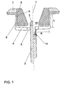
- the Abbrandschaltan extract shown in Fig. 1 is a Switching axis 1 formed approximately rotationally symmetrical. Along the switching axis 1 is a switching pin 2 with a Tip 3 made of burn-resistant material such.
- a first contact piece comprises a wreath arranged around the switching axis 1, radially against the same directed contact elements, which as elongated contact fingers 4 are formed, which at their Ends wear burners 5 made of burn-resistant material.
- the contact fingers 4 together form an approximately annular contact part, wherein the against the Switching axis 1 directed contact surfaces of Abbrandkmü. 5 one in the closed position on the outside of the Switch pin 2 present adjacent contact zone. from Abbrandkopf 5 apart, each contact finger 4 is in one piece with a bent by about 90 ° in the switch-on, so with the contact finger 4 a right angle including web 6 of harness philosophicaldem spring elastic Material produced and fixed to a housing part 7 anchored over which the bridge 6 with a first electric Connection is connected.
- the switching pin 2 forms against it a second contact piece, the z. B. via a flexible Cable or a sliding tulip with a second electrical Connection is connected.
- a support body. 8 fastened from electrically insulating material whose cylinder jacket-shaped outer side forms a support surface 9, at the webs 6 rest in the off position.
- the initial deflection can because of the high elasticity of the webs 6 pretty much be chosen large, so that a large burn-up reserve for Available.
- the support body 8 has a Open on which a surrounding the switching axis 1 nozzle 10 forms, in which in the closed position, the top of the third of the switching pin 2 protrudes.
- the radially outwardly directed parts of the current paths in The contact fingers 4 practice a relatively low electromagnetic force on each other and also the Action of passing through the switching pin 2 Section of the rung to the same can be neglected become.
- the subsequent parallel current paths through the Webs 6 attract each other, but is the radial Component of attraction because of the relatively large Distance to the switching axis 1 is not so great that Damage or excessive pressure of the contact fingers 4 against the switching pin 2, the excessive abrasion of the Abbrandkexcellent 5 and obstructions of the switching pin movement to could have a consequence, to be feared.
- the distance R of the web 6 from the switching axis 1 and the Length L of the same can be set on the contrary so that the mutual attraction of the contact fingers 4 in the typically expected currents due to the elastic deflection of the contact fingers 4 of the same against the switching pin 2 exerted contact pressure desired way amplified and in particular the between these parts have effective contact lift forces approximately compensated.
- Such compensation remains above all Fluctuations in the current received, since Contact lift forces and attractions in the same way depend on the same.
- the further movement of the Wennstattens 2 will be the same from the wreath of Contact fingers 4 pulled and the burn-off heads 5 of the same move against the switching axis 1 until the webs 6 at the Support surface 9 abut. Further radial movement of Contact finger 4 against the switching axis 1 under the influence the mutual attraction of the current paths through the bridges 6 is thus prevented.
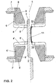
- the Abbrandschaltan extract shown in FIG A second embodiment of the invention corresponds to what the first contact piece, completely the first Embodiment.
- the second contact piece comprises in addition to the switching pin 2, a consumable contact arrangement, which in turn corresponds exactly to the first contact piece with Contact fingers 4 'with Abbrandgropfen 5', in the Closed position with its a second contact zone forming inner surfaces against the peripheral surface of the Press switch pin 2, wherein the contact fingers 4 'turn at webs 6 'angled about 90 ° and connect the same and a housing part 7 'with the second electrical connection are connected, so that the Contact finger 4 'at the same time the function of a sliding tulip perceive.
- the webs 6 ' are in the off position in turn on a support surface 9 ', which from the outside a support body 8 'is formed, which at the same time a the switching axis 1 surrounding nozzle 10 'forms.
- the consumable switching arrangement according to the in Fig. 3rd illustrated third embodiment of the invention otherwise corresponds otherwise completely to that according to the second Embodiment, but are the contact fingers 4, 4 'respectively Abbrandringe 12, 12 'assigned. They form parts of cup-shaped shields 13, 13 ', which, with the webs. 6 or 6 'electrically connected, in each case the others Surround parts of the contact pieces and completely shield.
- the arc 11 commutates rapidly from the erosion heads 5 of the contact fingers 4 on the Abbrandring 12, while from the top 3 of the switch pin 2 in essentially on the Abbrandring 12 'commutated, which the Burning of the contact fingers 4, 4 'is reduced and thus their Lifespan increased.
- the Abbrandschaltan extract shown in Fig. 4 according A fourth embodiment of the invention corresponds to FIG their basic structure of those after the first one Embodiment, but are the contact fingers 4, from which the first contact piece is aligned so that it with the switching axis 1 viewed in the switching direction an angle Include ⁇ of about 65 °.
- the support body 8 forms in this case a truncated cone-shaped support surface 9, which lies at a distance below the contact fingers 4 and limits their mobility against the switching axis 1. The course of an elimination corresponds to that described in connection with the Abbrandschaltan extract according to the first embodiment of the invention.
- the contact pieces 4 project only with at least theirs front ends burn-resistant tips 17 by corresponding openings in the panel 16 while same one stop for front shoulders of her make wider body 18.
- the electrical contact with the Retaining ring 15 is made by contact blades 19.
- the contact piece 4 By means of a pressing against his back Spring element, namely a coil spring 21, which on a the recess 14 final outer panel 20 of the Retainers 15 is supported, the contact piece 4 " each with a radially acting against the switching axis 1 Force applied.
- the current paths are from the contact zone, d. H. the the switching pin 2 touching the front ends of the tips 17th the contact pieces 4 "out radially outwards, so that the electromagnetic forces that they make against each other exercise, no significant influence on the contact pressure have, with the contact pieces 4 "against the peripheral surface of the switch pin 2.
- the required contact pressure is applied by the coil spring 21.
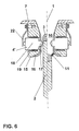
- the Abbrandschaltan extract shown in Fig. 6 according to a sixth embodiment of the invention are largely as described above, but are the Recesses 14 formed continuously and the body 18th the contact pieces 4 "so long that they something about the Outside of the retaining ring 15 protrude.
- a spring element is in each case a leaf spring 22 is provided, which against the Rear of the contact piece 4 "presses.
- the Abbrandschaltan extract shown in Fig. 7 according to a seventh embodiment of the invention again the one described above, but are the Contact pieces 4 "of constant diameter and each guided in sliding guides 23, which in the Recesses 14 are attached. Also, the electric Contact with the retaining ring 15 here in each case via a flexible Band 24 made of highly conductive material, one of which End with the back of the contact piece 4 "electric conductively connected, in particular welded, while the other end with the retaining ring 15 electrically conductive connected is.
- the first contact piece as rigid first switching ring 25 made of burn-resistant material formed, which is fixed in the housing and the same also electrically conductive with the first electrical Connection is connected.
- the second contact piece comprises a switching pin 2, the, via a in Ausschaltetraum limited compressible cup spring package 26 supported, axially slidably mounted on a holder 27 which by a not shown switching drive along the Switching axis 1 can be moved, and a contact part, as a circular disk 28 of highly conductive elastic material, z.
- B. CuBe or CuCrZr is trained.
- the switching pin 2 has, compared to its tip to about the Distance between the first switching ring 25 and the second Switching ring 33 offset in Aus harshtraum, a circumferential Shoulder 34 on.
- In the closed position is the top of the switching pin 2, from the compressed cup spring package 26th with a sufficient contact pressure applied to the Front of the first switching ring 25 all around, while the Shoulder 34 against a contact zone on the second switching ring 33rd presses and the sectors 32 of the same under elastic Deformation of the sectors 31 of the annular disc 28 axially in Switching direction slightly deflects, so that through the elastic restoring forces of the sectors 31 also here sufficient contact pressure is given.
- the burnup circuit arrangement shown schematically in FIG. 9 according to a ninth embodiment of the invention is formed similar to the above-described.
- the first contact piece as the inner Rand ago slotted first annular disc 35 highly conductive resilient material formed.
- the Switch pin 2 is rigidly on a not shown by a shift drive along the shift axis 1 slidably Attached bracket and a sliding tulip 36 with the second electrical connection electrically conductively connected.
- the elastic restoring force of the first annular disc 35, the inner edge 37 of burn-resistant material a in the switch-on axially in the switch-on easily forms a deflected contact zone, provides a sufficient Contact pressure safe.
- the second contact piece comprises a the second electrical connection electrically conductive connected rigid second annular disc 38 burn-resistant material whose internal diameter only is slightly larger than the diameter of the Wegliches 2. It acts as Abbrandring, on the Turn off the one arc base point of the switch pin 2 skips.
Landscapes
- Arc-Extinguishing Devices That Are Switches (AREA)
- Contacts (AREA)
Description
- Fig. 1
- einen axialen Längsschnitt durch eine Abbrandschaltanordnung gemäss einer ersten Ausführungsform der Erfindung, links in Einschalt-, rechts in Ausschaltstellung,
- Fig. 2
- einen axialen Längsschnitt durch eine Abbrandschaltanordnung gemäss einer zweiten Ausführungsform der Erfindung, links in Einschalt-, rechts in Ausschaltstellung,
- Fig. 3
- einen axialen Längsschnitt durch eine Abbrandschaltanordnung gemäss einer dritten Ausführungsform der Erfindung, links in Einschalt-, rechts in Ausschaltstellung,
- Fig. 4
- einen axialen Längsschnitt durch eine Abbrandschaltanordnung gemäss einer vierten Ausführungsform der Erfindung, links in Einschalt-, rechts in Ausschaltstellung,
- Fig. 5
- einen axialen Längsschnitt durch eine Abbrandschaltanordnung gemäss einer fünften Ausführungsform der Erfindung, links in Einschalt-, rechts in Ausschaltstellung,
- Fig. 6
- einen axialen Längsschnitt durch eine Abbrandschaltanordnung gemäss einer sechsten Ausführungsform der Erfindung, links in Einschalt-, rechts in Ausschaltstellung,
- Fig. 7
- einen axialen Längsschnitt durch eine Abbrandschaltanordnung gemäss einer siebten Ausführungsform der Erfindung, links in Einschalt-, rechts in Ausschaltstellung,
- Fig. 8a
- einen axialen Längsschnitt durch eine Abbrandschaltanordnung gemäss einer achten Ausführungsform der Erfindung, links in der Einschaltstellung,rechts kurz vor Erreichen der Einschaltstellung,
- Fig. 8b
- eine axiale Draufsicht auf einen Teil der Abbrandschaltanordnung nach Fig. 8a,
- Fig. 8c
- einen Schnitt längs C-C in Fig. 8b,
- Fig. 9
- einen axialen Längsschnitt durch eine Abbrandschaltanordnung gemäss einer neunten Ausführungsform der Erfindung, links in Einschalt-, rechts in Ausschaltstellung.
- 1
- Schaltachse
- 2
- Schaltstift
- 3
- Spitze des Schaltstiftes 2
- 4, 4'
- Kontaktfinger
- 4"
- Kontaktstücke
- 5, 5'
- Abbrandköpfe
- 6, 6'
- Stege
- 7, 7'
- Gehäuseteile
- 8, 8'
- Stützkörper
- 9, 9'
- Stützflächen
- 10, 10'
- Düsen
- 11
- Lichtbogen
- 12, 12'
- Abbrandringe
- 13, 13'
- Abschirmungen
- 14
- Ausnehmungen
- 15
- Haltering
- 16
- Verkleidung des Halterings 15
- 17
- Spitze des Kontaktstücks 4"
- 18
- Körper des Kontaktstücks 4"
- 19
- Kontaktlamellen
- 20
- Aussenwand des Halterings 15
- 21
- Spiralfedern
- 22
- Blattfedern
- 23
- Gleitführungen
- 24
- Band
- 25
- erster Schaltring
- 26
- Tellerfedernpaket
- 27
- Halterung
- 28
- Kreisringscheibe
- 29
- Aussenring der Kreisringscheibe 28
- 30
- Schlitze in Kreisringscheibe 28
- 31
- Sektoren der Kreisringscheibe 28
- 32
- Sektoren des zweiten Schaltrings 33
- 33
- zweiter Schaltring
- 34
- Schulter des Schaltstiftes 2
- 35
- erste Kreisringscheibe
- 36
- Gleittulpe
- 37
- Innenrand der ersten Kreisringscheibe 35
- 38
- zweite Kreisringscheibe
Claims (20)
- Abbrandschaltanordnung mit, in einem Gehäuse, einem ersten Schaltstück, welches mindestens in einer Einschaltstellung mit einem ersten elektrischen Anschluss verbunden ist und einem zweiten Schaltstück, welches mindestens in der Einschaltstellung mit einem zweiten elektrischen Anschluss verbunden ist und welches einen Schaltstift (2) umfasst, welcher mittels eines Schaltantriebs längs einer Schaltachse (1) relativ zum ersten Schaltstück zwischen der Einschaltstellung, in welcher das erste Schaltstück den Schaltstift (2) berührt, so dass die Abbrandschaltanordnung einen Strompfad zwischen dem ersten elektrischen Anschluss und dem zweiten elektrischen Anschluss schliesst und einer Ausschaltstellung, in welcher der Schaltstift (2) vom ersten Schaltstück beabstandet ist, umstellbar ist, mit mindestens einem Kontaktteil, das einem der Schaltstücke angehört und welches mit einer die Schaltachse umgebenden Kontaktzone in der Einschaltstellung den Schaltstift (2) berührt, dadurch gekennzeichnet, dass das Kontaktteil die Schaltachse (1) kranzartig umgibt und sich von einem Innenrand, welcher die Kontaktzone bildet, ausgehend derart erweitert, dass es mit der Schaltachse (1) einen Winkel von mindestens 45° einschliesst.
- Abbrandschaltanordnung nach Anspruch 1, dadurch gekennzeichnet, dass der Winkel zwischen der Schaltachse (1) und dem Kontaktteil mindestens 60° beträgt.
- Abbrandschaltanordnung nach Anspruch 3, dadurch gekennzeichnet, dass das Kontaktteil mindestens annähernd radial von der Schaltachse (1) nach aussen gerichtet ist.
- Abbrandschaltanordnung nach einem der Ansprüche 1 bis 3, dadurch gekennzeichnet, dass die Kontaktzone in der Einschaltstellung unter der Einwirkung des Schaltstiftes (2) elastisch ausgelenkt ist.
- Abbrandschaltanordnung nach einem der Ansprüche 1 bis 4, dadurch gekennzeichnet, dass das Kontaktteil aus mehreren mindestens annähernd gerade gegen die Schaltachse (1) gerichteten Kontaktelementen besteht.
- Abbrandschaltanordnung nach Anspruch 5, dadurch gekennzeichnet, dass jedes Kontaktelement als länglicher Kontaktfinger (4, 4') ausgebildet ist.
- Abbrandschaltanordnung nach einem der Ansprüche 4 bis 6, dadurch gekennzeichnet, dass die Kontaktzone in der Einschaltstellung im wesentlichen radial ausgelenkt ist und den Schaltstift (2) an seiner Umfangsfläche berührt.
- Abbrandschaltanordnung nach den Ansprüchen 6 und 7, dadurch gekennzeichnet, dass jeder Kontaktfinger (4, 4') an einen Steg (6, 6') aus flexiblem, insbesondere federelastischem elektrisch leitendem Material, welcher mindestens einen Teil der elektrisch leitenden Verbindung zwischen dem Kontaktfinger (4, 4') und dem entsprechenden elektrischen Anschluss bildet, abgewinkelt anschliesst.
- Abbrandschaltanordnung nach Anspruch 8, dadurch gekennzeichnet, dass der Steg (6, 6') jeweils mindestens annähernd parallel zur Schaltachse (1) und an seinem dem Kontaktfinger (4, 4') abgewandten Ende fest verankert ist.
- Abbrandschaltanordnung nach den Ansprüchen 6 und 7, dadurch gekennzeichnet, dass jeder Kontaktfinger (4) mindestens annähernd gerade ist, mindestens über einen Teil seiner Länge aus flexiblem, insbesondere federelastischem Material besteht und an seinem der Schaltachse (1) abgewandten Ende fest verankert ist.
- Abbrandschaltanordnung nach Anspruch 10, dadurch gekennzeichnet, dass jeder Kontaktfinger (4) schräg gegen die Schaltachse (1) gerichtet ist.
- Abbrandschaltanordnung nach einem der Ansprüche 8 bis 11, dadurch gekennzeichnet, dass der Steg (6) bzw. der Kontaktfinger (4, 4') in der Ausschaltstellung an einer nach aussen weisenden Stützfläche (9, 9') anliegt.
- Abbrandanordnung nach Anspruch 7, dadurch gekennzeichnet, dass die Kontaktelemente jeweils als radial verschieblich in einer in der Einschaltstellung den Schaltstift (2) umgebenden Halterung gelagerte Kontaktstücke (4") ausgebildet sind.
- Abbrandschaltanordnung nach Anspruch 13, dadurch gekennzeichnet, dass die Halterung als die Schaltachse (1) umgebender Haltering (15) ausgebildet ist mit mindestens gegen die Schaltachse (1) offenen radialen Ausnehmungen (14) zur Aufnahme der Kontaktstücke (4").
- Abbrandschaltanordnung nach einem der Ansprüche 4 bis 6, dadurch gekennzeichnet, dass die Kontaktzone in der Einschaltstellung im wesentlichen axial ausgelenkt ist und den Schaltstift (2) an einer im wesentlichen gegen die Einschaltrichtung weisenden Stossfläche berührt.
- Abbrandschaltanordnung nach Anspruch 15, dadurch gekennzeichnet, dass die Kontaktelemente durch Schlitze (30) getrennte Sektoren (31) einer Kreisringscheibe (28) aus federelastischem Material umfassen, an deren Innenrand die Kontaktzone angeordnet ist.
- Abbrandschaltanordnung nach Anspruch 16, dadurch gekennzeichnet, dass die Schlitze (30) radial verlaufen.
- Abbrandschaltanordnung nach Anspruch 16 oder 17, dadurch gekennzeichnet, dass die Kreisringscheibe (28) einen geschlossenen Aussenring (29) umfasst.
- Abbrandschaltanordnung nach einem der Ansprüche 15 bis 18, dadurch gekennzeichnet, dass die Stossfläche von einer umlaufenden Schulter (34) des Schaltstiftes gebildet wird.
- Abbrandschaltanordnung nach einem der Ansprüche 15 bis 18, dadurch gekennzeichnet, dass die Stossfläche von der Spitze (3) des Schaltstiftes (2) gebildet wird.
Applications Claiming Priority (2)
| Application Number | Priority Date | Filing Date | Title |
|---|---|---|---|
| DE19816509 | 1998-04-14 | ||
| DE19816509A DE19816509B4 (de) | 1998-04-14 | 1998-04-14 | Abbrandschaltanordnung |
Publications (3)
| Publication Number | Publication Date |
|---|---|
| EP0951038A1 EP0951038A1 (de) | 1999-10-20 |
| EP0951038B1 true EP0951038B1 (de) | 2005-10-05 |
| EP0951038B2 EP0951038B2 (de) | 2011-12-14 |
Family
ID=7864486
Family Applications (1)
| Application Number | Title | Priority Date | Filing Date |
|---|---|---|---|
| EP99810170A Expired - Lifetime EP0951038B2 (de) | 1998-04-14 | 1999-03-01 | Abbrandschaltanordnung |
Country Status (5)
| Country | Link |
|---|---|
| US (1) | US6100492A (de) |
| EP (1) | EP0951038B2 (de) |
| JP (1) | JP4255566B2 (de) |
| CN (1) | CN1132213C (de) |
| DE (2) | DE19816509B4 (de) |
Families Citing this family (11)
| Publication number | Priority date | Publication date | Assignee | Title |
|---|---|---|---|---|
| DE50308222D1 (de) * | 2003-07-02 | 2007-10-31 | Abb Technology Ag | Kontaktfinger für Hochleistungsschalter |
| US8878092B2 (en) | 2009-06-25 | 2014-11-04 | Mitsubishi Electric Corporation | Gas-insulated switchgear |
| CN102714112B (zh) | 2010-02-04 | 2016-01-27 | 三菱电机株式会社 | 气体断路器 |
| CN104126213B (zh) | 2012-03-16 | 2016-08-24 | 三菱电机株式会社 | 气体断路器 |
| FR2997222B1 (fr) * | 2012-10-19 | 2015-01-16 | Alstom Technology Ltd | Dispositif d'etablissement et/ou de coupure de courant a contacts permanents a usure reduite |
| WO2014076040A1 (en) * | 2012-11-13 | 2014-05-22 | Abb Technology Ag | Contact system |
| DE102013106727B4 (de) * | 2013-06-26 | 2015-08-06 | Doduco Gmbh | Kontaktstift für Hochspannungs-Leistungsschalter, Verfahren zu seiner Herstellung und Hochspannungs-Leistungsschalter mit einem solchen Kontaktstift |
| JP6382543B2 (ja) * | 2014-03-24 | 2018-08-29 | 株式会社東芝 | ガス遮断器 |
| JP6320106B2 (ja) * | 2014-03-25 | 2018-05-09 | 株式会社東芝 | ガス遮断器 |
| WO2019092861A1 (ja) * | 2017-11-10 | 2019-05-16 | 株式会社 東芝 | ガス遮断器 |
| US11545322B2 (en) * | 2018-10-26 | 2023-01-03 | Kabushiki Kaisha Toshiba | Gas circuit breaker |
Family Cites Families (19)
| Publication number | Priority date | Publication date | Assignee | Title |
|---|---|---|---|---|
| FR691621A (fr) * | 1929-03-09 | 1930-10-23 | Elin Ag Fur Elek Sche Ind | Interrupteur de courant de forte intensité, en particulier interrupteur à huile pour grande puissance de coupure |
| DE1923974U (de) † | 1965-05-20 | 1965-09-23 | Licentia Gmbh | Druckkontakt fuer hochspannungs-leistungsschalter. |
| NL160974C (nl) * | 1971-09-07 | 1979-12-17 | Coq Bv | Persgasschakelaar met samenwerkende buisvormige contactstukken. |
| DE2423103C2 (de) * | 1974-05-13 | 1986-09-18 | Brown, Boveri & Cie Ag, 6800 Mannheim | Elektrischer Druckgasleistungsschalter |
| JPS5718663Y2 (de) * | 1976-07-07 | 1982-04-19 | ||
| US4152560A (en) * | 1977-02-14 | 1979-05-01 | Gould Inc. | Stationary contact structure for high voltage gas blast circuit interrupter with deformed slotted contact finger configuration |
| CH645204A5 (de) * | 1979-05-25 | 1984-09-14 | Bbc Brown Boveri & Cie | Elektrischer schalter fuer grosse stroeme. |
| CH649416A5 (de) * | 1980-01-25 | 1985-05-15 | Sprecher & Schuh Ag | Druckgasschalter. |
| JPS6341723Y2 (de) * | 1980-04-25 | 1988-11-01 | ||
| EP0067460B2 (de) * | 1981-06-12 | 1990-03-21 | BBC Brown Boveri AG | Hochspannungsleistungsschalter |
| DE3440212A1 (de) * | 1984-10-10 | 1986-04-17 | BBC Aktiengesellschaft Brown, Boveri & Cie., Baden, Aargau | Druckgasschalter |
| FR2644624B1 (fr) * | 1989-03-17 | 1996-03-22 | Merlin Gerin | Disjoncteur electrique a autoexpansion et a gaz isolant |
| JPH0324233U (de) * | 1989-07-20 | 1991-03-13 | ||
| FR2691574A1 (fr) * | 1992-05-21 | 1993-11-26 | Nora Permelec France Sarl De | Contact électrique pour circuit haute intensité. |
| DE4402935A1 (de) * | 1994-02-01 | 1995-08-03 | Abb Patent Gmbh | Kontaktsystem für einen Hochspannungsleistungsschalter |
| US5495084A (en) * | 1994-04-05 | 1996-02-27 | Abb Power T&D Company Inc. | Slip-through mounting structure for circuit interrupter |
| DE19613568A1 (de) * | 1996-04-04 | 1997-10-09 | Asea Brown Boveri | Leistungsschalter |
| DE19613569A1 (de) * | 1996-04-04 | 1997-10-09 | Asea Brown Boveri | Leistungsschalter |
| DE19648633A1 (de) * | 1996-11-25 | 1998-05-28 | Asea Brown Boveri | Elektrisches Schaltgerät |
-
1998
- 1998-04-14 DE DE19816509A patent/DE19816509B4/de not_active Expired - Lifetime
-
1999
- 1999-03-01 DE DE59912612T patent/DE59912612D1/de not_active Expired - Lifetime
- 1999-03-01 EP EP99810170A patent/EP0951038B2/de not_active Expired - Lifetime
- 1999-04-13 US US09/290,387 patent/US6100492A/en not_active Expired - Lifetime
- 1999-04-13 JP JP10582199A patent/JP4255566B2/ja not_active Expired - Fee Related
- 1999-04-14 CN CN99106055A patent/CN1132213C/zh not_active Expired - Fee Related
Also Published As
| Publication number | Publication date |
|---|---|
| JP4255566B2 (ja) | 2009-04-15 |
| DE19816509A1 (de) | 1999-10-21 |
| US6100492A (en) | 2000-08-08 |
| CN1232281A (zh) | 1999-10-20 |
| EP0951038A1 (de) | 1999-10-20 |
| EP0951038B2 (de) | 2011-12-14 |
| JPH11329176A (ja) | 1999-11-30 |
| DE59912612D1 (de) | 2005-11-10 |
| DE19816509B4 (de) | 2006-08-10 |
| CN1132213C (zh) | 2003-12-24 |
Similar Documents
| Publication | Publication Date | Title |
|---|---|---|
| DE2723552C2 (de) | Elektrischer Druckgasschalter | |
| EP0844631A2 (de) | Elektrisches Schaltgerät | |
| DE102010031907B9 (de) | Unidirektional schaltendes DC-Schütz | |
| DE19837945A1 (de) | Schaltanordnung und Verfahren zu ihrer Herstellung | |
| DE19803974C1 (de) | Kontaktanordnung für einen elektrischen Leistungsschalter | |
| EP0951038B2 (de) | Abbrandschaltanordnung | |
| EP1766646B1 (de) | Vakuumschaltkammer und kontaktanordnung für einen vakuumschalter | |
| DE19631323C1 (de) | Druckgasschalter | |
| DE3107525C2 (de) | Druckgas-Leistungsschalter | |
| EP1859460A1 (de) | Elektrische kontaktanordnung mit einem ersten und einem zweiten kontaktstück | |
| EP2063442A1 (de) | Leistungsschalter mit flexiblen Leitern | |
| DE19517615A1 (de) | Leistungsschalter | |
| EP0988638B1 (de) | Abbrandschaltanordnung | |
| EP0197339B1 (de) | Hochspannungsschalter mit Einschaltwiderstand | |
| DE69508680T2 (de) | Hochspannungsschalter | |
| DE3736835A1 (de) | Hochspannungsschalter | |
| DE19816507A1 (de) | Abbrandschaltanordnung | |
| CH667940A5 (de) | Elektrischer schalter. | |
| EP0290950A1 (de) | Druckgasschalter | |
| DE19524217A1 (de) | Leistungsschalter | |
| DE2815059C2 (de) | Schaltstückanordnung für Niederspannungs-Vakuumschütze | |
| DE3235353C2 (de) | ||
| DE19603081B4 (de) | Hochspannungs-Vakuumschalter | |
| DE3134644C2 (de) | ||
| DE2644745A1 (de) | Leistungstrennschalter |
Legal Events
| Date | Code | Title | Description |
|---|---|---|---|
| PUAI | Public reference made under article 153(3) epc to a published international application that has entered the european phase |
Free format text: ORIGINAL CODE: 0009012 |
|
| AK | Designated contracting states |
Kind code of ref document: A1 Designated state(s): CH DE FR IT LI |
|
| AX | Request for extension of the european patent |
Free format text: AL;LT;LV;MK;RO;SI |
|
| 17P | Request for examination filed |
Effective date: 20000217 |
|
| RAP1 | Party data changed (applicant data changed or rights of an application transferred) |
Owner name: ABB HOCHSPANNUNGSTECHNIK AG |
|
| AKX | Designation fees paid |
Free format text: CH DE FR IT LI |
|
| RAP1 | Party data changed (applicant data changed or rights of an application transferred) |
Owner name: ABB SCHWEIZ AG |
|
| GRAP | Despatch of communication of intention to grant a patent |
Free format text: ORIGINAL CODE: EPIDOSNIGR1 |
|
| GRAS | Grant fee paid |
Free format text: ORIGINAL CODE: EPIDOSNIGR3 |
|
| GRAA | (expected) grant |
Free format text: ORIGINAL CODE: 0009210 |
|
| AK | Designated contracting states |
Kind code of ref document: B1 Designated state(s): CH DE FR IT LI |
|
| REG | Reference to a national code |
Ref country code: CH Ref legal event code: EP |
|
| REF | Corresponds to: |
Ref document number: 59912612 Country of ref document: DE Date of ref document: 20051110 Kind code of ref document: P |
|
| ET | Fr: translation filed | ||
| PLBI | Opposition filed |
Free format text: ORIGINAL CODE: 0009260 |
|
| 26 | Opposition filed |
Opponent name: SIEMENS AG ABTEILUNG: CT IP PTD Effective date: 20060704 |
|
| PLAX | Notice of opposition and request to file observation + time limit sent |
Free format text: ORIGINAL CODE: EPIDOSNOBS2 |
|
| PLAF | Information modified related to communication of a notice of opposition and request to file observations + time limit |
Free format text: ORIGINAL CODE: EPIDOSCOBS2 |
|
| PLBB | Reply of patent proprietor to notice(s) of opposition received |
Free format text: ORIGINAL CODE: EPIDOSNOBS3 |
|
| PLAB | Opposition data, opponent's data or that of the opponent's representative modified |
Free format text: ORIGINAL CODE: 0009299OPPO |
|
| PGFP | Annual fee paid to national office [announced via postgrant information from national office to epo] |
Ref country code: IT Payment date: 20090323 Year of fee payment: 11 |
|
| PG25 | Lapsed in a contracting state [announced via postgrant information from national office to epo] |
Ref country code: IT Free format text: LAPSE BECAUSE OF NON-PAYMENT OF DUE FEES Effective date: 20100301 |
|
| PUAH | Patent maintained in amended form |
Free format text: ORIGINAL CODE: 0009272 |
|
| STAA | Information on the status of an ep patent application or granted ep patent |
Free format text: STATUS: PATENT MAINTAINED AS AMENDED |
|
| 27A | Patent maintained in amended form |
Effective date: 20111214 |
|
| AK | Designated contracting states |
Kind code of ref document: B2 Designated state(s): CH DE FR IT LI |
|
| REG | Reference to a national code |
Ref country code: CH Ref legal event code: AEN Free format text: AUFRECHTERHALTUNG DES PATENTES IN GEAENDERTER FORM |
|
| REG | Reference to a national code |
Ref country code: DE Ref legal event code: R102 Ref document number: 59912612 Country of ref document: DE Effective date: 20111214 |
|
| REG | Reference to a national code |
Ref country code: FR Ref legal event code: PLFP Year of fee payment: 18 |
|
| REG | Reference to a national code |
Ref country code: FR Ref legal event code: PLFP Year of fee payment: 19 |
|
| PGFP | Annual fee paid to national office [announced via postgrant information from national office to epo] |
Ref country code: FR Payment date: 20170322 Year of fee payment: 19 Ref country code: DE Payment date: 20170322 Year of fee payment: 19 Ref country code: CH Payment date: 20170322 Year of fee payment: 19 |
|
| REG | Reference to a national code |
Ref country code: DE Ref legal event code: R119 Ref document number: 59912612 Country of ref document: DE |
|
| REG | Reference to a national code |
Ref country code: CH Ref legal event code: PL |
|
| PG25 | Lapsed in a contracting state [announced via postgrant information from national office to epo] |
Ref country code: DE Free format text: LAPSE BECAUSE OF NON-PAYMENT OF DUE FEES Effective date: 20181002 |
|
| PG25 | Lapsed in a contracting state [announced via postgrant information from national office to epo] |
Ref country code: LI Free format text: LAPSE BECAUSE OF NON-PAYMENT OF DUE FEES Effective date: 20180331 Ref country code: CH Free format text: LAPSE BECAUSE OF NON-PAYMENT OF DUE FEES Effective date: 20180331 |
|
| PG25 | Lapsed in a contracting state [announced via postgrant information from national office to epo] |
Ref country code: FR Free format text: LAPSE BECAUSE OF NON-PAYMENT OF DUE FEES Effective date: 20180331 |