EP0947623A1 - Textilbahn, Verfahren zur Herstellung einer solchen Textilbahn sowie Vorrichtung zur Durchführung dieses Verfahrens - Google Patents
Textilbahn, Verfahren zur Herstellung einer solchen Textilbahn sowie Vorrichtung zur Durchführung dieses Verfahrens Download PDFInfo
- Publication number
- EP0947623A1 EP0947623A1 EP98106032A EP98106032A EP0947623A1 EP 0947623 A1 EP0947623 A1 EP 0947623A1 EP 98106032 A EP98106032 A EP 98106032A EP 98106032 A EP98106032 A EP 98106032A EP 0947623 A1 EP0947623 A1 EP 0947623A1
- Authority
- EP
- European Patent Office
- Prior art keywords
- thread
- web
- textile web
- textile
- threads
- Prior art date
- Legal status (The legal status is an assumption and is not a legal conclusion. Google has not performed a legal analysis and makes no representation as to the accuracy of the status listed.)
- Granted
Links
Images
Classifications
-
- D—TEXTILES; PAPER
- D21—PAPER-MAKING; PRODUCTION OF CELLULOSE
- D21F—PAPER-MAKING MACHINES; METHODS OF PRODUCING PAPER THEREON
- D21F7/00—Other details of machines for making continuous webs of paper
- D21F7/08—Felts
- D21F7/083—Multi-layer felts
-
- D—TEXTILES; PAPER
- D03—WEAVING
- D03D—WOVEN FABRICS; METHODS OF WEAVING; LOOMS
- D03D1/00—Woven fabrics designed to make specified articles
-
- B—PERFORMING OPERATIONS; TRANSPORTING
- B29—WORKING OF PLASTICS; WORKING OF SUBSTANCES IN A PLASTIC STATE IN GENERAL
- B29C—SHAPING OR JOINING OF PLASTICS; SHAPING OF MATERIAL IN A PLASTIC STATE, NOT OTHERWISE PROVIDED FOR; AFTER-TREATMENT OF THE SHAPED PRODUCTS, e.g. REPAIRING
- B29C65/00—Joining or sealing of preformed parts, e.g. welding of plastics materials; Apparatus therefor
- B29C65/02—Joining or sealing of preformed parts, e.g. welding of plastics materials; Apparatus therefor by heating, with or without pressure
- B29C65/08—Joining or sealing of preformed parts, e.g. welding of plastics materials; Apparatus therefor by heating, with or without pressure using ultrasonic vibrations
-
- B—PERFORMING OPERATIONS; TRANSPORTING
- B29—WORKING OF PLASTICS; WORKING OF SUBSTANCES IN A PLASTIC STATE IN GENERAL
- B29C—SHAPING OR JOINING OF PLASTICS; SHAPING OF MATERIAL IN A PLASTIC STATE, NOT OTHERWISE PROVIDED FOR; AFTER-TREATMENT OF THE SHAPED PRODUCTS, e.g. REPAIRING
- B29C65/00—Joining or sealing of preformed parts, e.g. welding of plastics materials; Apparatus therefor
- B29C65/48—Joining or sealing of preformed parts, e.g. welding of plastics materials; Apparatus therefor using adhesives, i.e. using supplementary joining material; solvent bonding
- B29C65/4805—Joining or sealing of preformed parts, e.g. welding of plastics materials; Apparatus therefor using adhesives, i.e. using supplementary joining material; solvent bonding characterised by the type of adhesives
- B29C65/481—Non-reactive adhesives, e.g. physically hardening adhesives
- B29C65/4815—Hot melt adhesives, e.g. thermoplastic adhesives
-
- B—PERFORMING OPERATIONS; TRANSPORTING
- B29—WORKING OF PLASTICS; WORKING OF SUBSTANCES IN A PLASTIC STATE IN GENERAL
- B29C—SHAPING OR JOINING OF PLASTICS; SHAPING OF MATERIAL IN A PLASTIC STATE, NOT OTHERWISE PROVIDED FOR; AFTER-TREATMENT OF THE SHAPED PRODUCTS, e.g. REPAIRING
- B29C65/00—Joining or sealing of preformed parts, e.g. welding of plastics materials; Apparatus therefor
- B29C65/48—Joining or sealing of preformed parts, e.g. welding of plastics materials; Apparatus therefor using adhesives, i.e. using supplementary joining material; solvent bonding
- B29C65/50—Joining or sealing of preformed parts, e.g. welding of plastics materials; Apparatus therefor using adhesives, i.e. using supplementary joining material; solvent bonding using adhesive tape, e.g. thermoplastic tape; using threads or the like
- B29C65/5007—Joining or sealing of preformed parts, e.g. welding of plastics materials; Apparatus therefor using adhesives, i.e. using supplementary joining material; solvent bonding using adhesive tape, e.g. thermoplastic tape; using threads or the like characterised by the structure of said adhesive tape, threads or the like
- B29C65/5035—Joining or sealing of preformed parts, e.g. welding of plastics materials; Apparatus therefor using adhesives, i.e. using supplementary joining material; solvent bonding using adhesive tape, e.g. thermoplastic tape; using threads or the like characterised by the structure of said adhesive tape, threads or the like being in thread form, i.e. in the form of a single filament, e.g. in the form of a single coated filament
-
- B—PERFORMING OPERATIONS; TRANSPORTING
- B29—WORKING OF PLASTICS; WORKING OF SUBSTANCES IN A PLASTIC STATE IN GENERAL
- B29C—SHAPING OR JOINING OF PLASTICS; SHAPING OF MATERIAL IN A PLASTIC STATE, NOT OTHERWISE PROVIDED FOR; AFTER-TREATMENT OF THE SHAPED PRODUCTS, e.g. REPAIRING
- B29C65/00—Joining or sealing of preformed parts, e.g. welding of plastics materials; Apparatus therefor
- B29C65/48—Joining or sealing of preformed parts, e.g. welding of plastics materials; Apparatus therefor using adhesives, i.e. using supplementary joining material; solvent bonding
- B29C65/50—Joining or sealing of preformed parts, e.g. welding of plastics materials; Apparatus therefor using adhesives, i.e. using supplementary joining material; solvent bonding using adhesive tape, e.g. thermoplastic tape; using threads or the like
- B29C65/5042—Joining or sealing of preformed parts, e.g. welding of plastics materials; Apparatus therefor using adhesives, i.e. using supplementary joining material; solvent bonding using adhesive tape, e.g. thermoplastic tape; using threads or the like covering both elements to be joined
-
- B—PERFORMING OPERATIONS; TRANSPORTING
- B29—WORKING OF PLASTICS; WORKING OF SUBSTANCES IN A PLASTIC STATE IN GENERAL
- B29C—SHAPING OR JOINING OF PLASTICS; SHAPING OF MATERIAL IN A PLASTIC STATE, NOT OTHERWISE PROVIDED FOR; AFTER-TREATMENT OF THE SHAPED PRODUCTS, e.g. REPAIRING
- B29C65/00—Joining or sealing of preformed parts, e.g. welding of plastics materials; Apparatus therefor
- B29C65/48—Joining or sealing of preformed parts, e.g. welding of plastics materials; Apparatus therefor using adhesives, i.e. using supplementary joining material; solvent bonding
- B29C65/50—Joining or sealing of preformed parts, e.g. welding of plastics materials; Apparatus therefor using adhesives, i.e. using supplementary joining material; solvent bonding using adhesive tape, e.g. thermoplastic tape; using threads or the like
- B29C65/5092—Joining or sealing of preformed parts, e.g. welding of plastics materials; Apparatus therefor using adhesives, i.e. using supplementary joining material; solvent bonding using adhesive tape, e.g. thermoplastic tape; using threads or the like characterised by the tape handling mechanisms, e.g. using vacuum
-
- B—PERFORMING OPERATIONS; TRANSPORTING
- B29—WORKING OF PLASTICS; WORKING OF SUBSTANCES IN A PLASTIC STATE IN GENERAL
- B29C—SHAPING OR JOINING OF PLASTICS; SHAPING OF MATERIAL IN A PLASTIC STATE, NOT OTHERWISE PROVIDED FOR; AFTER-TREATMENT OF THE SHAPED PRODUCTS, e.g. REPAIRING
- B29C66/00—General aspects of processes or apparatus for joining preformed parts
- B29C66/01—General aspects dealing with the joint area or with the area to be joined
- B29C66/05—Particular design of joint configurations
- B29C66/10—Particular design of joint configurations particular design of the joint cross-sections
- B29C66/11—Joint cross-sections comprising a single joint-segment, i.e. one of the parts to be joined comprising a single joint-segment in the joint cross-section
- B29C66/114—Single butt joints
- B29C66/1142—Single butt to butt joints
-
- B—PERFORMING OPERATIONS; TRANSPORTING
- B29—WORKING OF PLASTICS; WORKING OF SUBSTANCES IN A PLASTIC STATE IN GENERAL
- B29C—SHAPING OR JOINING OF PLASTICS; SHAPING OF MATERIAL IN A PLASTIC STATE, NOT OTHERWISE PROVIDED FOR; AFTER-TREATMENT OF THE SHAPED PRODUCTS, e.g. REPAIRING
- B29C66/00—General aspects of processes or apparatus for joining preformed parts
- B29C66/40—General aspects of joining substantially flat articles, e.g. plates, sheets or web-like materials; Making flat seams in tubular or hollow articles; Joining single elements to substantially flat surfaces
- B29C66/41—Joining substantially flat articles ; Making flat seams in tubular or hollow articles
- B29C66/43—Joining a relatively small portion of the surface of said articles
- B29C66/432—Joining a relatively small portion of the surface of said articles for making tubular articles or closed loops, e.g. by joining several sheets ; for making hollow articles or hollow preforms
- B29C66/4322—Joining a relatively small portion of the surface of said articles for making tubular articles or closed loops, e.g. by joining several sheets ; for making hollow articles or hollow preforms by joining a single sheet to itself
-
- B—PERFORMING OPERATIONS; TRANSPORTING
- B29—WORKING OF PLASTICS; WORKING OF SUBSTANCES IN A PLASTIC STATE IN GENERAL
- B29C—SHAPING OR JOINING OF PLASTICS; SHAPING OF MATERIAL IN A PLASTIC STATE, NOT OTHERWISE PROVIDED FOR; AFTER-TREATMENT OF THE SHAPED PRODUCTS, e.g. REPAIRING
- B29C66/00—General aspects of processes or apparatus for joining preformed parts
- B29C66/40—General aspects of joining substantially flat articles, e.g. plates, sheets or web-like materials; Making flat seams in tubular or hollow articles; Joining single elements to substantially flat surfaces
- B29C66/41—Joining substantially flat articles ; Making flat seams in tubular or hollow articles
- B29C66/43—Joining a relatively small portion of the surface of said articles
- B29C66/432—Joining a relatively small portion of the surface of said articles for making tubular articles or closed loops, e.g. by joining several sheets ; for making hollow articles or hollow preforms
- B29C66/4329—Joining a relatively small portion of the surface of said articles for making tubular articles or closed loops, e.g. by joining several sheets ; for making hollow articles or hollow preforms the joint lines being transversal but non-orthogonal with respect to the axis of said tubular articles, i.e. being oblique
-
- B—PERFORMING OPERATIONS; TRANSPORTING
- B29—WORKING OF PLASTICS; WORKING OF SUBSTANCES IN A PLASTIC STATE IN GENERAL
- B29C—SHAPING OR JOINING OF PLASTICS; SHAPING OF MATERIAL IN A PLASTIC STATE, NOT OTHERWISE PROVIDED FOR; AFTER-TREATMENT OF THE SHAPED PRODUCTS, e.g. REPAIRING
- B29C66/00—General aspects of processes or apparatus for joining preformed parts
- B29C66/70—General aspects of processes or apparatus for joining preformed parts characterised by the composition, physical properties or the structure of the material of the parts to be joined; Joining with non-plastics material
- B29C66/72—General aspects of processes or apparatus for joining preformed parts characterised by the composition, physical properties or the structure of the material of the parts to be joined; Joining with non-plastics material characterised by the structure of the material of the parts to be joined
- B29C66/729—Textile or other fibrous material made from plastics
-
- B—PERFORMING OPERATIONS; TRANSPORTING
- B29—WORKING OF PLASTICS; WORKING OF SUBSTANCES IN A PLASTIC STATE IN GENERAL
- B29C—SHAPING OR JOINING OF PLASTICS; SHAPING OF MATERIAL IN A PLASTIC STATE, NOT OTHERWISE PROVIDED FOR; AFTER-TREATMENT OF THE SHAPED PRODUCTS, e.g. REPAIRING
- B29C66/00—General aspects of processes or apparatus for joining preformed parts
- B29C66/80—General aspects of machine operations or constructions and parts thereof
- B29C66/83—General aspects of machine operations or constructions and parts thereof characterised by the movement of the joining or pressing tools
- B29C66/836—Moving relative to and tangentially to the parts to be joined, e.g. transversely to the displacement of the parts to be joined, e.g. using a X-Y table
-
- D—TEXTILES; PAPER
- D06—TREATMENT OF TEXTILES OR THE LIKE; LAUNDERING; FLEXIBLE MATERIALS NOT OTHERWISE PROVIDED FOR
- D06H—MARKING, INSPECTING, SEAMING OR SEVERING TEXTILE MATERIALS
- D06H5/00—Seaming textile materials
-
- D—TEXTILES; PAPER
- D21—PAPER-MAKING; PRODUCTION OF CELLULOSE
- D21F—PAPER-MAKING MACHINES; METHODS OF PRODUCING PAPER THEREON
- D21F1/00—Wet end of machines for making continuous webs of paper
- D21F1/0027—Screen-cloths
- D21F1/0054—Seams thereof
-
- B—PERFORMING OPERATIONS; TRANSPORTING
- B29—WORKING OF PLASTICS; WORKING OF SUBSTANCES IN A PLASTIC STATE IN GENERAL
- B29C—SHAPING OR JOINING OF PLASTICS; SHAPING OF MATERIAL IN A PLASTIC STATE, NOT OTHERWISE PROVIDED FOR; AFTER-TREATMENT OF THE SHAPED PRODUCTS, e.g. REPAIRING
- B29C66/00—General aspects of processes or apparatus for joining preformed parts
- B29C66/70—General aspects of processes or apparatus for joining preformed parts characterised by the composition, physical properties or the structure of the material of the parts to be joined; Joining with non-plastics material
- B29C66/71—General aspects of processes or apparatus for joining preformed parts characterised by the composition, physical properties or the structure of the material of the parts to be joined; Joining with non-plastics material characterised by the composition of the plastics material of the parts to be joined
-
- B—PERFORMING OPERATIONS; TRANSPORTING
- B29—WORKING OF PLASTICS; WORKING OF SUBSTANCES IN A PLASTIC STATE IN GENERAL
- B29C—SHAPING OR JOINING OF PLASTICS; SHAPING OF MATERIAL IN A PLASTIC STATE, NOT OTHERWISE PROVIDED FOR; AFTER-TREATMENT OF THE SHAPED PRODUCTS, e.g. REPAIRING
- B29C66/00—General aspects of processes or apparatus for joining preformed parts
- B29C66/80—General aspects of machine operations or constructions and parts thereof
- B29C66/84—Specific machine types or machines suitable for specific applications
- B29C66/861—Hand-held tools
-
- Y—GENERAL TAGGING OF NEW TECHNOLOGICAL DEVELOPMENTS; GENERAL TAGGING OF CROSS-SECTIONAL TECHNOLOGIES SPANNING OVER SEVERAL SECTIONS OF THE IPC; TECHNICAL SUBJECTS COVERED BY FORMER USPC CROSS-REFERENCE ART COLLECTIONS [XRACs] AND DIGESTS
- Y10—TECHNICAL SUBJECTS COVERED BY FORMER USPC
- Y10S—TECHNICAL SUBJECTS COVERED BY FORMER USPC CROSS-REFERENCE ART COLLECTIONS [XRACs] AND DIGESTS
- Y10S162/00—Paper making and fiber liberation
- Y10S162/904—Paper making and fiber liberation with specified seam structure of papermaking belt
-
- Y—GENERAL TAGGING OF NEW TECHNOLOGICAL DEVELOPMENTS; GENERAL TAGGING OF CROSS-SECTIONAL TECHNOLOGIES SPANNING OVER SEVERAL SECTIONS OF THE IPC; TECHNICAL SUBJECTS COVERED BY FORMER USPC CROSS-REFERENCE ART COLLECTIONS [XRACs] AND DIGESTS
- Y10—TECHNICAL SUBJECTS COVERED BY FORMER USPC
- Y10T—TECHNICAL SUBJECTS COVERED BY FORMER US CLASSIFICATION
- Y10T428/00—Stock material or miscellaneous articles
- Y10T428/19—Sheets or webs edge spliced or joined
- Y10T428/192—Sheets or webs coplanar
- Y10T428/195—Beveled, stepped, or skived in thickness
Definitions
- the invention relates to a textile web, in particular as a base for paper machine clothing, the textile web Contains structural threads and at least seen in the width direction partly from several adjacent webs is composed, which together at their edges are welded. It also concerns a proceeding for the production of such a textile web.
- Textile webs of the aforementioned type are primarily used for Transport of paper webs used by a paper machine (GB-A-975 750; EP-A-0 665 329; EP-B-0 464 258). They are seen in the width direction made up of partial webs, the Width is much smaller than the final width of the textile web.
- the partial webs extend essentially in Longitudinal direction of the textile web and are formed in that one or more partial web strips in the longitudinal direction of the textile web as well as progressively wound helically across have been.
- the partial webs consist of structural threads, for example in the form of a fabric.
- the structural threads form a carrier on which a nonwoven fabric is woven is needled on one or both sides, so that the Textile web forms a felt.
- Such felts are special for guiding the paper webs in the press section Suitable for paper machines.
- the individual partial webs are used not only wrapped overlapping, but also with theirs Web edges side by side. To ensure sufficient lateral stability to get the web edges are connected. For this it is proposed to sew the web edges, too merge or weld, for example with ultrasonic welding (EP-A-0 665 329). Alternatively, it is provided to provide the web edges with seam loops and the Connection with the help of a plug wire through the seam loops to manufacture.
- the partial web is disadvantageous in that the structure of the textile web in the connection area considerably from the other areas deviates so that, for example, the permeability of the Textile web is changed, what is the use of the textile web in a paper machine for the quality of the paper web can affect. This is particularly the case when the web edges are sewn together.
- the sewing thread represents a foreign material that changes the character of the goods.
- the resistance to displacement is not satisfactory.
- some of the suggestions for connection the web edges are very labor intensive.
- the invention is therefore based on the object of a connection for the web edges of the partial webs of a textile web of the type mentioned in such a way that they are simple Way, preferably machine-made and thereby can also be designed so that the permeability of the Textile web in the connection area was not significantly changed becomes.
- Another task is to develop a method for Making such a connection and a device to provide for performing this procedure.
- this first-mentioned object is achieved by that the partial webs protrude at their web edges Have thread sections which overlap one another, and that over the overlapping areas of the thread sections laid at least one connecting thread and with the thread sections is welded.
- Basic idea of the invention So it is on the adjacent edges of the web provide overlapping thread sections and one above To lay connecting thread, which then with the individual thread sections is welded. This creates a mutual Connection of the two web edges.
- the thread sections and the connecting threads can be in one Density should be arranged that the permeability of the textile web in the area of the web edges is not essential changes.
- the inventive connection of the two web edges can also be carried out mechanically. The production the connection is thus time-saving and inexpensive.
- connecting threads on both sides of the textile web on thread sections are welded on. This allows improved strength achieve the connection.
- This is also suitable Embodiment in particular with structural threads in two Layers are arranged one above the other and in which both Layers protruding thread sections are formed.
- the protruding thread sections can be of various types be trained. So there is a possibility that To form thread sections in a loop. In simple Embodiment they are as protruding across the web edges Thread ends formed that when put together the web edges brought into interlocking overlap so that they are on one level.
- the connecting thread or Connecting threads are identical or are parallel to those along with structural threads.
- the distance should also be of the connecting thread to the parallel, neighboring ones Structural threads equal to the distance between these structural threads be with each other, so that the longitudinal thread distribution also in Connection area is constant.
- the structural threads are preferably part of a woven fabric, knitted fabric, Thread laid or an insert within a film or similar.
- the textile web can at least be provided with a fiber layer on one side, to give it a felt-like character.
- the textile web finally form, the front edges by means of a seam can be connected.
- the textile web at least in part from several juxtaposed, finite partial web strip built.
- the textile web is endless, wherein the manufacture can be done in the manner in which GB-A-975 750, EP-A-0 665 329 and EP-B-0 464 258 is.
- the partial webs are at least partially by one or more partial web strips, each Partial web strip in the longitudinal direction of the textile web as well as helical is progressively wrapped across it.
- the partial web strips themselves can also be endless and then be placed side by side.
- the method according to the invention is characterized in that that the partial webs at their web edges with protruding Thread sections are provided, which when putting together the partial webs are overlapped, and that on the overlapping areas of the thread sections at least one connecting thread along the web edges is placed and welded to the thread sections, preferably by means of ultrasound.
- the respective connecting thread at or immediately after Laying on to be welded to the thread sections To prevent the connecting thread from slipping.
- a device for performing the above-described method has a thread laying device for laying at least a connecting thread on overlapping thread sections on web edges of partial webs of a textile web and a welding device for welding the connecting thread with the thread sections.
- Such a device is basically also conceivable as a handheld device.
- a special drive to generate a relative movement between thread placement device and welding device on the one hand and textile web on the other hand is provided, so that the laying on and welding of the respective connecting thread essentially done mechanically.
- the device can, for example, be a support for have the stationary recordings of the textile webs, wherein then the thread laying device and the welding device are movably guided in parallel.
- the thread laying device and Welding device fixed to the device and a drive for Moving the textile web past both facilities is provided is.
- Such training is possible in particular if the textile web is endless, so that it is between two rollers can be spanned.
- the welding device must be able to connect the thread and to heat the protruding thread sections so that they develop adhesive strength at the connection points.
- An ultrasonic welding device is suitable for this, for example.
- the thread laying device preferably has a thread store, from which the connecting thread through the thread laying device is automatically deducted.
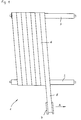
- the device 1 shown in Figure 1 has two spaced Rolls 2, 3, each driven in the same direction are. From a supply roll 4 is a textile strip 5 subtracted. The supply roll 4 is slightly inclined and is moved in the direction of arrow A when the trigger is removed. As a result, the textile strip 5 winds up helically the two rollers 2, 3 until a desired width is reached is. This can also be done in multiple layers by the Supply roll 4 moved back after reaching the final width is, the outlet angle adjusted accordingly becomes. Specifically, this is EP-A-0 665 329 and EP-B-0 464 258.
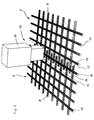
- Figure 2 shows a detail in an enlarged view of two adjacent sub-webs 6, 7, which are from the textile strip 5 placed next to each other by pulling off the supply roll 4 have been.
- the partial webs 6, 7 each exist from transverse threads - labeled 8 and 9, for example - which taken together form a cross thread.
- transverse threads 8, 9 and the longitudinal threads 10, 11 are at their crossing point with each other connected, for example by welding, gluing or similar.
- They are made of thermoplastic Plastics as used for paper machine tapes come, for example polyamide, polyester, etc. you can be designed as a monofilament or multifile.
- the partial webs 6, 7 have web edges 12, 13 which pass through the dashed lines are marked.
- the cross threads 8, 9 project beyond the web edges 12, 13 and form there Thread sections - designated 14 or 15, for example -, a thread section 14 or 15 of the one partial web 6, 7 into a gap between two thread sections 14 or 15 of the other partial web 6 or 7, so that the thread sections 14, 15 in the direction of the longitudinal threads 10, 11 seen overlap.
- the partial webs 6, 7 are thus against each other by half a center distance between two adjacent transverse threads 8 and 9 offset, so that they are zipper-like interlock.
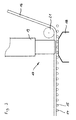
- the connection device 17 has an underside support beam 18, which is extends parallel to the rollers 2, 3 and the partial webs 6, 7 supported. Above the support beam 18 is a common one Ultrasonic welding device 19 arranged by the the connecting thread 16 is running. Through the ultrasonic welding device 19 it is heated so much that it partially plasticized and glued to the thread sections 14, 15 or attached.
- Thread laying device 20 with a laying roller 21 and a Thread store not shown here for the Connecting thread 16.
- the connecting thread is from this thread store 16 over the laying roller 21 on the thread sections 14, 15 pressed and then by plasticizing in the ultrasonic welding device 19 with the thread sections 14, 15 connected. This creates one firm connection between the two partial webs 6, 7.
- Another possibility is to use the partial webs 6, 7 not to put one against the other and alternately just everyone second cross thread 8, 9 with a protruding thread section to be provided so that the end faces of the transverse threads 8, 9 face each other with a small distance. Also in this Fall would the density of the thread sections 14, 15 of the Density of the transverse threads 8, 9 correspond.
- the partial webs 6, 7 are covered with a nonwoven fabric and needled this with the scrim. It can also the nonwoven is applied in a strip-like manner are, as shown in Figure 1 with the textile strip 5 is.
Landscapes
- Engineering & Computer Science (AREA)
- Mechanical Engineering (AREA)
- Textile Engineering (AREA)
- Treatment Of Fiber Materials (AREA)
- Paper (AREA)
- Woven Fabrics (AREA)
- Yarns And Mechanical Finishing Of Yarns Or Ropes (AREA)
- Decoration Of Textiles (AREA)
- Treatments For Attaching Organic Compounds To Fibrous Goods (AREA)
- Package Frames And Binding Bands (AREA)
- Respiratory Apparatuses And Protective Means (AREA)
Abstract
Description
- Figur 1
- eine Draufsicht auf eine Vorrichtung zur Herstellung einer Textilbahn;
- Figur 2
- eine perspektivische Ansicht der Strukturfäden von zwei Teilbahnen im Bereich ihrer Bahnränder mit einer Ultraschallschweißeinrichtung und
- Figur 3
- eine Seitenansicht der Anordnung gemäß Figur 2.
Claims (27)
- Textilbahn, insbesondere als Basis für Papiermaschinenbespannungen, wobei die Textilbahn Strukturfäden (8, 9, 10, 11) enthält und in Breitenrichtung gesehen wenigstens teilweise aus mehreren, aneinanderliegenden Teilbahnen (6, 7) zusammengesetzt ist, welche an ihren Bahnrändern (12, 13) miteinander verschweißt sind, dadurch gekennzeichnet, daß die Teilbahnen (6, 7) an ihren Bahnrändern (12, 13) überstehende Fadenabschnitte (14, 15) aufweisen, die überlappend ineinandergreifen, und daß über die Fadenabschnitte (14, 15) wenigstens ein Verbindungsfaden (16) gelegt und mit den Fadenabschnitten (14, 15) verschweißt ist.
- Textilbahn nach Anspruch 1, dadurch gekennzeichnet, daß Verbindungsfäden auf beiden Seiten der Teilbahnen an Fadenabschnitten angeschweißt sind.
- Textilbahn nach Anspruch 1 oder 2, dadurch gekennzeichnet, daß die Fadenabschnitte (14, 15) als quer über die Bahnränder (12, 13) vorstehende Fadenenden ausgebildet sind.
- Textilbahn nach einem der Ansprüche 1 bis 3, dadurch gekennzeichnet, daß Fadenabschnitte (14, 15) und Verbindungsfaden (16) in einer solchen Dichte vorhanden sind, daß die Durchlässigkeit der Textilbahn gleichmäßig ist.
- Textilbahn nach einem der Ansprüche 1 bis 4, dadurch gekennzeichnet, daß der Verbindungsfaden (16) bzw. die Verbindungsfäden identisch ist bzw. sind mit den parallel dazu verlaufenden Strukturfäden (10, 11).
- Textilbahn nach einem der Ansprüche 1 bis 5, dadurch gekennzeichnet, daß der Abstand des Verbindungsfadens (16) zu den parallel verlaufenden, benachbarten Strukturfäden (10, 11) gleich dem Abstand dieser Strukturfäden (10, 11) untereinander ist.
- Textilbahn nach einem der Ansprüche 1 bis 6, dadurch gekennzeichnet, daß die Strukturfäden (8, 9, 10, 11) Teil eines Gewebes, Gewirkes, Fadengeleges oder einer Einlage sind.
- Textilbahn nach einem der Ansprüche 1 bis 7, dadurch gekennzeichnet, daß die Textilbahn zumindest an einer Seite eine Faserschicht aufweist.
- Textilbahn nach einem der Ansprüche 1 bis 8, dadurch gekennzeichnet, daß die Textilbahn endlos ausgebildet ist.
- Textilbahn nach einem der Ansprüche 1 bis 9, dadurch gekennzeichnet, daß die Teilbahnen aus mehreren gleich langen Teilbahnstreifen gebildet sind.
- Textilbahn nach einem der Ansprüche 1 bis 10, dadurch gekennzeichnet, daß die Teilbahnen (6, 7) wenigstens teilweise von einem Teilbahnstreifen (5) gebildet sind, der in Längsrichtung der Textilbahn sowie wendelförmig quer dazu fortschreitend gewickelt ist.
- Textilbahn nach einem der Ansprüche 1 bis 11, dadurch gekennzeichnet, daß die Teilbahnstreifen endlos ausgebildet sind.
- Verfahren zur Herstellung einer Textilbahn, die textile Strukturfäden (8, 9, 10, 11) enthält, wobei die Teilbahn in wenigstens einer Richtung gesehen aus mehreren, aneinanderliegenden Teilbahnen (6, 7) aufgebaut wird, welche an ihren Bahnrändern (12, 13) miteinander verschweißt werden, dadurch gekennzeichnet, daß die Teilbahnen (6, 7) an ihren Bahnrändern (12, 13) mit überstehenden Fadenabschnitten (14, 15) versehen werden, welche beim Aneinanderlegen der Teilbahnen (6, 7) in gegenseitige Überlappung gebracht werden, und daß auf die Fadenabschnitte (14, 15) wenigstens ein Verbindungsfaden (16) längs der Bahnränder (12, 13) gelegt und mit den Fadenabschnitten (14, 15) verschweißt wird.
- Verfahren nach Anspruch 13, dadurch gekennzeichnet, daß Verbindungsfaden (16) und Fadenabschnitte (14, 15) ultraschallverschweißt werden.
- Verfahren nach Anspruch 13 oder 14, dadurch gekennzeichnet, daß der jeweilige Verbindungsfaden (16) beim oder unmittelbar nach dem Auflegen mit den Fadenabschnitten (14, 15) verschweißt wird.
- Verfahren nach einem der Ansprüche 13 bis 15, dadurch gekennzeichnet, daß jeweils ein Verbindungsfaden an der Oberseite und einer an der Unterseite der Textilbahn angeschweißt wird.
- Verfahren nach einem der Ansprüche 13 bis 16, dadurch gekennzeichnet, daß Fadenabschnitte (14, 15) und Verbindungsfaden (16) in einer solchen Dichte miteinander verbunden werden, daß keine wesentliche Änderung der Durchlässigkeit in diesem Bereich eintritt.
- Verfahren nach einem der Ansprüche 13 bis 17, dadurch gekennzeichnet, daß die Fadenabschnitte (14, 15) als quer über die Bahnränder (12, 13) vorstehende Fadenenden ausgebildet werden.
- Verfahren nach einem der Ansprüche 13 bis 18, dadurch gekennzeichnet, daß ein Verbindungsfaden (16) bzw. Verbindungsfäden verwendet wird bzw. werden, der bzw. die identisch ist bzw. sind mit den parallel dazu verlaufenden Strukturfäden (10, 11).
- Verfahren nach einem der Ansprüche 13 bis 19, dadurch gekennzeichnet, daß die Verbindung der Bahnränder (12, 13) in der Weise hergestellt wird, daß der Abstand des Verbindungsfadens (16) zu den parallel verlaufenden, benachbarten Strukturfäden (10, 11) gleich den Abständen dieser Strukturfäden (10, 11) untereinander ist.
- Verfahren nach einem der Ansprüche 13 bis 20, dadurch gekennzeichnet, daß die Strukturfäden (8, 9, 10, 11) als Teil eines Gewebes, Gewirkes, Fadengeleges oder einer Einlage ausgebildet werden.
- Vorrichtung zur Durchführung des Verfahrens nach einem der Ansprüche 13 bis 21, gekennzeichnet durch eine Fadenauflegeeinrichtung (20) zum Auflegen wenigstens eines Verbindungsfadens (16) auf sich überlappende Fadenabschnitte (14, 15) an Bahnrändern (12, 13) von Teilbahnen (6, 7) einer Textilbahn sowie durch eine Schweißeinrichtung (19) zum Verschweißen des Verbindungsfadens (16) mit den Fadenabschnitten (14, 15).
- Vorrichtung nach Anspruch 22, dadurch gekennzeichnet, daß ein Antrieb zur Erzeugung einer Relativbewegung zwischen Fadenauflegeeinrichtung (20) und Schweißeinrichtung (19) einerseits sowie Textilbahn andererseits vorgesehen ist.
- Vorrichtung nach Anspruch 22 oder 23, dadurch gekennzeichnet, daß eine Auflage für die stationäre Aufnahme der Textilbahn vorgesehen ist und Fadenauflegeeinrichtung und Schweißeinrichtung parallel dazu beweglich geführt sind.
- Vorrichtung nach Anspruch 22 oder 23, dadurch gekennzeichnet, daß Fadenauflegeeinrichtung (20) und Schweißeinrichtung (19) gerätefest angeordnet und ein Antrieb zum Bewegen der Textilbahn an beiden Einrichtungen vorbei vorgesehen ist.
- Vorrichtung nach einem der Ansprüche 22 bis 25, dadurch gekennzeichnet, daß die Schweißeinrichtung als Ultraschallschweißeinrichtung (19) ausgebildet ist.
- Vorrichtung nach einem der Ansprüche 22 bis 26, dadurch gekennzeichnet, daß die Fadenauflegeeinrichtung (20) einen Fadenspeicher aufweist.
Priority Applications (15)
| Application Number | Priority Date | Filing Date | Title |
|---|---|---|---|
| AT98106032T ATE213793T1 (de) | 1998-04-02 | 1998-04-02 | Textilbahn, verfahren zur herstellung einer solchen textilbahn sowie vorrichtung zur durchführung dieses verfahrens |
| DE59803190T DE59803190D1 (de) | 1998-04-02 | 1998-04-02 | Textilbahn, Verfahren zur Herstellung einer solchen Textilbahn sowie Vorrichtung zur Durchführung dieses Verfahrens |
| ES98106032T ES2170976T3 (es) | 1998-04-02 | 1998-04-02 | Banda textil especialmente utilizable como base para revestimientos de maquinas papeleras. |
| EP98106032A EP0947623B1 (de) | 1998-04-02 | 1998-04-02 | Textilbahn, Verfahren zur Herstellung einer solchen Textilbahn sowie Vorrichtung zur Durchführung dieses Verfahrens |
| TW088103875A TW580529B (en) | 1998-04-02 | 1999-03-12 | Textile length, process for producing one such textile length, and a device for executing this process |
| CA002265403A CA2265403C (en) | 1998-04-02 | 1999-03-17 | Textile length, process for producing one such textile length, and a device for executing this process |
| US09/275,813 US6162518A (en) | 1998-04-02 | 1999-03-25 | Textile length, process for producing one such textile length, and a device for executing this process |
| AU22487/99A AU750609B2 (en) | 1998-04-02 | 1999-03-29 | Textile length, process for producing one such textile length, and a device for executing this process |
| NO19991539A NO314460B1 (no) | 1998-04-02 | 1999-03-30 | Tekstilbane, fremgangsmåte for fremstilling av en slik tekstilbane like somanordning for gjennomföring av disse fremgangsmåter |
| KR1019990011135A KR19990082799A (ko) | 1998-04-02 | 1999-03-31 | 직물렝스와직물렝스생산방법및상기생산방법을수행하기위한장치 |
| BRPI9901224-3A BR9901224B1 (pt) | 1998-04-02 | 1999-04-01 | seÇço tÊxtil, processo para fabricaÇço de uma seÇço tÊxtil bem como dispositivo para concretizaÇço do processo. |
| IDP990298D ID22396A (id) | 1998-04-02 | 1999-04-01 | Panjang tekstil, proses untuk memproduksi panjang tekstil seperti itu, dan peralatan untuk melaksanakan proses ini |
| ZA9902507A ZA992507B (en) | 1998-04-02 | 1999-04-01 | Textile length, process for producing one such textile length, and a device for executing this process. |
| JP11095684A JP2000027089A (ja) | 1998-04-02 | 1999-04-02 | 帯状体およびこの帯状体を製造する方法、並びにこの方法を実施するための装置 |
| CN99104792A CN1100179C (zh) | 1998-04-02 | 1999-04-02 | 织造轨带及其制造方法以及实现这种方法的装置 |
Applications Claiming Priority (1)
| Application Number | Priority Date | Filing Date | Title |
|---|---|---|---|
| EP98106032A EP0947623B1 (de) | 1998-04-02 | 1998-04-02 | Textilbahn, Verfahren zur Herstellung einer solchen Textilbahn sowie Vorrichtung zur Durchführung dieses Verfahrens |
Publications (2)
| Publication Number | Publication Date |
|---|---|
| EP0947623A1 true EP0947623A1 (de) | 1999-10-06 |
| EP0947623B1 EP0947623B1 (de) | 2002-02-27 |
Family
ID=8231703
Family Applications (1)
| Application Number | Title | Priority Date | Filing Date |
|---|---|---|---|
| EP98106032A Expired - Lifetime EP0947623B1 (de) | 1998-04-02 | 1998-04-02 | Textilbahn, Verfahren zur Herstellung einer solchen Textilbahn sowie Vorrichtung zur Durchführung dieses Verfahrens |
Country Status (15)
| Country | Link |
|---|---|
| US (1) | US6162518A (de) |
| EP (1) | EP0947623B1 (de) |
| JP (1) | JP2000027089A (de) |
| KR (1) | KR19990082799A (de) |
| CN (1) | CN1100179C (de) |
| AT (1) | ATE213793T1 (de) |
| AU (1) | AU750609B2 (de) |
| BR (1) | BR9901224B1 (de) |
| CA (1) | CA2265403C (de) |
| DE (1) | DE59803190D1 (de) |
| ES (1) | ES2170976T3 (de) |
| ID (1) | ID22396A (de) |
| NO (1) | NO314460B1 (de) |
| TW (1) | TW580529B (de) |
| ZA (1) | ZA992507B (de) |
Cited By (13)
| Publication number | Priority date | Publication date | Assignee | Title |
|---|---|---|---|---|
| EP1045066A3 (de) * | 1999-04-12 | 2001-09-19 | Albany International Corp. | Verfahren zum Verbinden von Gittervliesen |
| EP1209283A1 (de) * | 2000-11-23 | 2002-05-29 | Thomas Josef Heimbach Gesellschaft mit beschränkter Haftung | Textilbahn, insbesondere Papiermaschinenbespannung |
| EP1359251A1 (de) * | 2002-04-25 | 2003-11-05 | Thomas Josef Heimbach Gesellschaft mit beschränkter Haftung & Co. | Papiermaschinenbespannung sowie Verfahren zu deren Herstellung |
| WO2009032666A1 (en) * | 2007-09-05 | 2009-03-12 | Albany International Corp. | Method of forming a fabric seam by ultrasonic gap welding of a flat woven fabric |
| EP2067896A1 (de) | 2007-12-04 | 2009-06-10 | Helmbach GmbH & Co.KG | Verfahren zur Herstellung eines Machinenfilzes sowie Maschinenfilz |
| US7722743B2 (en) | 2006-03-21 | 2010-05-25 | Heimbach Gmbh & Co. Kg | Method for manufacturing a felt belt, and felt belt |
| US7897018B2 (en) | 2007-09-05 | 2011-03-01 | Albany International Corp. | Process for producing papermaker's and industrial fabrics |
| US8062480B2 (en) | 2007-09-05 | 2011-11-22 | Albany International Corp. | Process for producing papermaker's and industrial fabric seam and seam produced by that method |
| US8088256B2 (en) | 2007-09-05 | 2012-01-03 | Albany International Corp. | Process for producing papermaker's and industrial fabric seam and seam produced by that method |
| EP2518209A1 (de) * | 2002-12-31 | 2012-10-31 | Albany International Corporation | Verfahren zum Binden von Strukturelementen einer Papiermaschine und von Industriegeweben sowie damit hergestellte Gewebe |
| DE202021104492U1 (de) | 2021-08-20 | 2021-10-06 | Heimbach Gmbh | Textilbahn sowie Verwendung einer solchen |
| EP4180363A1 (de) * | 2021-11-16 | 2023-05-17 | Stadler Anlagenbau GmbH | Gurtband für förderanlagen |
| EP4237615A1 (de) * | 2020-10-28 | 2023-09-06 | Voith Patent GmbH | Gewebeverbindung und papiermaschinenbespannung |
Families Citing this family (31)
| Publication number | Priority date | Publication date | Assignee | Title |
|---|---|---|---|---|
| US6723208B1 (en) * | 2000-10-05 | 2004-04-20 | Albany International Corp. | Method for producing spiral wound paper machine clothing |
| AU2002225981B2 (en) * | 2000-10-23 | 2006-03-09 | Albany International Corp. | Seamed papermaker's fabrics |
| US6565713B2 (en) * | 2001-02-03 | 2003-05-20 | Albany International Corp. | Laminated structure for paper machine press fabric and method making |
| US6491794B2 (en) * | 2001-03-29 | 2002-12-10 | Albany International Corp. | Base structure for seamed papermaker's fabrics |
| US6702927B2 (en) * | 2002-03-27 | 2004-03-09 | Albany International Corp. | Seaming of spirally wound paper machine clothing |
| DE50206804D1 (de) * | 2002-04-25 | 2006-06-22 | Heimbach Gmbh Thomas Josef | Papiermaschinenbespannung sowie Verfahren zu deren Herstellung |
| WO2003102298A1 (en) * | 2002-05-30 | 2003-12-11 | National Wire Fabric Inc. | Broadloom fabric and method of forming the same |
| JP2004036046A (ja) * | 2002-07-04 | 2004-02-05 | Ichikawa Woolen Textile Co Ltd | 抄紙用プレスフェルト |
| FI113674B (fi) * | 2002-12-18 | 2004-05-31 | Tamfelt Oyj Abp | Puristinhuopa |
| US6878238B2 (en) | 2002-12-19 | 2005-04-12 | Kimberly-Clark Worldwide, Inc. | Non-woven through air dryer and transfer fabrics for tissue making |
| US6875315B2 (en) * | 2002-12-19 | 2005-04-05 | Kimberly-Clark Worldwide, Inc. | Non-woven through air dryer and transfer fabrics for tissue making |
| US7147756B2 (en) * | 2003-02-11 | 2006-12-12 | Albany International Corp. | Unique fabric structure for industrial fabrics |
| US7141142B2 (en) | 2003-09-26 | 2006-11-28 | Kimberly-Clark Worldwide, Inc. | Method of making paper using reformable fabrics |
| US8840683B2 (en) * | 2003-11-19 | 2014-09-23 | Albany International Corp. | Industrial textile fabric |
| US7238259B2 (en) * | 2003-12-10 | 2007-07-03 | Albany International Corp. | Methods of seaming |
| US20060010568A1 (en) * | 2004-01-27 | 2006-01-19 | Wiles William A | Helmet sweat band |
| JP4593326B2 (ja) * | 2004-03-26 | 2010-12-08 | イチカワ株式会社 | シュープレス用ベルト |
| US7410554B2 (en) * | 2004-11-11 | 2008-08-12 | Albany International Corp. | Unique modular construction for use as a forming fabric in papermaking or tissue or nonwovens |
| US7207355B2 (en) * | 2005-05-06 | 2007-04-24 | Astenjohnson, Inc. | Multi-axial seamed papermaking fabric and method |
| CN101041922B (zh) * | 2006-03-21 | 2010-06-09 | 亨巴赫有限公司&两合公司 | 制造毡带的方法和毡带 |
| JP4917388B2 (ja) * | 2006-08-28 | 2012-04-18 | 日本フエルト株式会社 | 製紙用フェルト |
| US7712336B2 (en) * | 2007-01-31 | 2010-05-11 | Albany International Corp. | Subassembly for industrial fabrics |
| JP5227738B2 (ja) * | 2008-10-23 | 2013-07-03 | 日本フエルト株式会社 | 製紙用フェルトの製造方法 |
| DE102011012156A1 (de) * | 2011-02-23 | 2012-08-23 | Dbw Holding Gmbh | Verfahren zur Herstellung eines Formmatrials aus Fasermaterialien und Vorrichtung hierüber |
| DE102011012202B4 (de) * | 2011-02-23 | 2014-09-25 | Dbw Holding Gmbh | Schalldämpfereinsatz für Kraftfahrzeuge und Verfahren zur Herstellung hiervon |
| US10703066B2 (en) | 2013-11-25 | 2020-07-07 | Federal-Mogul Powertrain Llc | Spiral wrapped nonwoven sleeve and method of construction thereof |
| JP6497678B2 (ja) | 2015-07-21 | 2019-04-10 | イチカワ株式会社 | 抄紙用フェルト及びその製造方法 |
| JP6521447B2 (ja) | 2015-07-28 | 2019-05-29 | イチカワ株式会社 | 抄紙用フェルト |
| EP3235949B1 (de) | 2016-04-21 | 2018-05-23 | Ichikawa Co., Ltd. | Papiermaschinenfilz |
| JP7398043B2 (ja) * | 2019-09-27 | 2023-12-14 | イチカワ株式会社 | 抄紙用フェルトおよびその製造方法 |
| DE202022101383U1 (de) * | 2022-03-15 | 2022-03-31 | Heimbach Gmbh | Transportband, insbesondere Transferband für eine Papiermaschine |
Citations (6)
| Publication number | Priority date | Publication date | Assignee | Title |
|---|---|---|---|---|
| US1821455A (en) * | 1929-12-12 | 1931-09-01 | Eastwood Wire Corp | Woven-wire belt for paper-making machines |
| GB975750A (en) * | 1962-01-12 | 1964-11-18 | Karl Plate | Flexible sieve of tubular or endless belt form |
| US4090897A (en) * | 1977-04-22 | 1978-05-23 | The Sinclair Company | Ultrasonic welding of thermoplastic fabrics |
| US4501782A (en) * | 1983-11-18 | 1985-02-26 | Mac/Gil Ltd. | Method for bonding webs employing ultrasonic energy |
| US5360656A (en) * | 1990-12-17 | 1994-11-01 | Albany International Corp. | Press felt and method of manufacturing it |
| EP0464258B1 (de) * | 1990-06-13 | 1996-03-13 | Thomas Josef Heimbach GmbH & Co. | Filz, insbesondere Papiermaschinenfilz sowie Verfahren zu dessen Herstellung |
Family Cites Families (7)
| Publication number | Priority date | Publication date | Assignee | Title |
|---|---|---|---|---|
| US3622415A (en) * | 1967-12-22 | 1971-11-23 | Lindsay Wire Weaving Co | Papermaking fabric seam and method of making the same |
| DE2436928B2 (de) * | 1974-07-31 | 1976-06-10 | Siemens AG, 1000 Berlin und 8000 München | Verfahren zur herstellung eines ringfoermigen ein- oder mehrfarbigen farbbandes sowie gemaess dem verfahren hergestelltes farbband |
| JPS57154447A (en) * | 1981-03-12 | 1982-09-24 | Nitto Electric Ind Co | Production of non-woven fabric tube |
| US4560427A (en) * | 1984-12-03 | 1985-12-24 | Branson Ultrasonics Corporation | Ultrasonic seal and cut method and apparatus |
| JPH0696397B2 (ja) * | 1985-11-21 | 1994-11-30 | ヤマハ発動機株式会社 | 小型ジエツト推進艇 |
| JP3126464B2 (ja) * | 1992-02-17 | 2001-01-22 | シャープ株式会社 | 画像形成方法 |
| US5785818A (en) * | 1997-02-27 | 1998-07-28 | Jwi Ltd. | Multiaxial pin seamed papermaker's press felt |
-
1998
- 1998-04-02 ES ES98106032T patent/ES2170976T3/es not_active Expired - Lifetime
- 1998-04-02 DE DE59803190T patent/DE59803190D1/de not_active Expired - Lifetime
- 1998-04-02 AT AT98106032T patent/ATE213793T1/de active
- 1998-04-02 EP EP98106032A patent/EP0947623B1/de not_active Expired - Lifetime
-
1999
- 1999-03-12 TW TW088103875A patent/TW580529B/zh not_active IP Right Cessation
- 1999-03-17 CA CA002265403A patent/CA2265403C/en not_active Expired - Fee Related
- 1999-03-25 US US09/275,813 patent/US6162518A/en not_active Expired - Lifetime
- 1999-03-29 AU AU22487/99A patent/AU750609B2/en not_active Ceased
- 1999-03-30 NO NO19991539A patent/NO314460B1/no not_active IP Right Cessation
- 1999-03-31 KR KR1019990011135A patent/KR19990082799A/ko not_active Ceased
- 1999-04-01 ZA ZA9902507A patent/ZA992507B/xx unknown
- 1999-04-01 BR BRPI9901224-3A patent/BR9901224B1/pt not_active IP Right Cessation
- 1999-04-01 ID IDP990298D patent/ID22396A/id unknown
- 1999-04-02 CN CN99104792A patent/CN1100179C/zh not_active Expired - Fee Related
- 1999-04-02 JP JP11095684A patent/JP2000027089A/ja active Pending
Patent Citations (6)
| Publication number | Priority date | Publication date | Assignee | Title |
|---|---|---|---|---|
| US1821455A (en) * | 1929-12-12 | 1931-09-01 | Eastwood Wire Corp | Woven-wire belt for paper-making machines |
| GB975750A (en) * | 1962-01-12 | 1964-11-18 | Karl Plate | Flexible sieve of tubular or endless belt form |
| US4090897A (en) * | 1977-04-22 | 1978-05-23 | The Sinclair Company | Ultrasonic welding of thermoplastic fabrics |
| US4501782A (en) * | 1983-11-18 | 1985-02-26 | Mac/Gil Ltd. | Method for bonding webs employing ultrasonic energy |
| EP0464258B1 (de) * | 1990-06-13 | 1996-03-13 | Thomas Josef Heimbach GmbH & Co. | Filz, insbesondere Papiermaschinenfilz sowie Verfahren zu dessen Herstellung |
| US5360656A (en) * | 1990-12-17 | 1994-11-01 | Albany International Corp. | Press felt and method of manufacturing it |
Cited By (20)
| Publication number | Priority date | Publication date | Assignee | Title |
|---|---|---|---|---|
| EP1477608A1 (de) * | 1999-04-12 | 2004-11-17 | Albany International Corp. | Verfahren zum Verbinden von Gittervliesen |
| EP1045066A3 (de) * | 1999-04-12 | 2001-09-19 | Albany International Corp. | Verfahren zum Verbinden von Gittervliesen |
| EP1209283A1 (de) * | 2000-11-23 | 2002-05-29 | Thomas Josef Heimbach Gesellschaft mit beschränkter Haftung | Textilbahn, insbesondere Papiermaschinenbespannung |
| US6811849B2 (en) | 2000-11-23 | 2004-11-02 | Thomas Josef Heimbach Gesellschaft Mit Beschrankter Haftung & Co. | Textile web, especially a textile-covered web for a paper-making machine |
| EP1359251A1 (de) * | 2002-04-25 | 2003-11-05 | Thomas Josef Heimbach Gesellschaft mit beschränkter Haftung & Co. | Papiermaschinenbespannung sowie Verfahren zu deren Herstellung |
| US6896771B2 (en) | 2002-04-25 | 2005-05-24 | Heimbach Gmbh & Co. | Paper machine clothing and a method of producing the same |
| EP2518209A1 (de) * | 2002-12-31 | 2012-10-31 | Albany International Corporation | Verfahren zum Binden von Strukturelementen einer Papiermaschine und von Industriegeweben sowie damit hergestellte Gewebe |
| US7722743B2 (en) | 2006-03-21 | 2010-05-25 | Heimbach Gmbh & Co. Kg | Method for manufacturing a felt belt, and felt belt |
| US7897018B2 (en) | 2007-09-05 | 2011-03-01 | Albany International Corp. | Process for producing papermaker's and industrial fabrics |
| US7794555B2 (en) | 2007-09-05 | 2010-09-14 | Albany International Corp. | Formation of a fabric seam by ultrasonic gap welding of a flat woven fabric |
| US8062480B2 (en) | 2007-09-05 | 2011-11-22 | Albany International Corp. | Process for producing papermaker's and industrial fabric seam and seam produced by that method |
| US8088256B2 (en) | 2007-09-05 | 2012-01-03 | Albany International Corp. | Process for producing papermaker's and industrial fabric seam and seam produced by that method |
| WO2009032666A1 (en) * | 2007-09-05 | 2009-03-12 | Albany International Corp. | Method of forming a fabric seam by ultrasonic gap welding of a flat woven fabric |
| US8647474B2 (en) | 2007-09-05 | 2014-02-11 | Albany International Corp | Process for producing papermaker's and industrial fabric seam and seam produced by that method |
| US8801880B2 (en) | 2007-09-05 | 2014-08-12 | Albany International Corp. | Formation of a fabric seam by ultrasonic gap welding of a flat woven fabric |
| EP2067896A1 (de) | 2007-12-04 | 2009-06-10 | Helmbach GmbH & Co.KG | Verfahren zur Herstellung eines Machinenfilzes sowie Maschinenfilz |
| EP4237615A1 (de) * | 2020-10-28 | 2023-09-06 | Voith Patent GmbH | Gewebeverbindung und papiermaschinenbespannung |
| DE202021104492U1 (de) | 2021-08-20 | 2021-10-06 | Heimbach Gmbh | Textilbahn sowie Verwendung einer solchen |
| EP4137636A1 (de) | 2021-08-20 | 2023-02-22 | Heimbach GmbH | Textilbahn sowie verwendung einer solchen |
| EP4180363A1 (de) * | 2021-11-16 | 2023-05-17 | Stadler Anlagenbau GmbH | Gurtband für förderanlagen |
Also Published As
| Publication number | Publication date |
|---|---|
| JP2000027089A (ja) | 2000-01-25 |
| ZA992507B (en) | 1999-10-05 |
| NO991539L (no) | 1999-10-04 |
| CN1230614A (zh) | 1999-10-06 |
| TW580529B (en) | 2004-03-21 |
| NO314460B1 (no) | 2003-03-24 |
| KR19990082799A (ko) | 1999-11-25 |
| AU2248799A (en) | 1999-10-14 |
| NO991539D0 (no) | 1999-03-30 |
| CA2265403A1 (en) | 1999-10-02 |
| ATE213793T1 (de) | 2002-03-15 |
| US6162518A (en) | 2000-12-19 |
| BR9901224A (pt) | 2000-03-21 |
| CA2265403C (en) | 2004-06-15 |
| ID22396A (id) | 1999-10-07 |
| BR9901224B1 (pt) | 2008-11-18 |
| EP0947623B1 (de) | 2002-02-27 |
| DE59803190D1 (de) | 2002-04-04 |
| CN1100179C (zh) | 2003-01-29 |
| ES2170976T3 (es) | 2002-08-16 |
| AU750609B2 (en) | 2002-07-25 |
Similar Documents
| Publication | Publication Date | Title |
|---|---|---|
| EP0947623B1 (de) | Textilbahn, Verfahren zur Herstellung einer solchen Textilbahn sowie Vorrichtung zur Durchführung dieses Verfahrens | |
| DE2447706C2 (de) | Inlett und Verfahren zu seiner Herstellung | |
| DE69418597T2 (de) | Verfahren und vorrichtung zur herstellung eines polartikels und die hergestellten produkte | |
| EP2067896B1 (de) | Verfahren zur Herstellung eines Maschinenfilzes sowie Maschinenfilz | |
| DE4010086C2 (de) | Kontinuierliches Verfahren und Vorrichtung zur kontinuierlichen Herstellung eines verstärkten laminierten Tuches für Segel | |
| DE60033976T2 (de) | Verfahren zum Verbinden von Gittervliesen | |
| DE60201576T2 (de) | Mehrschichtstruktur für papiermaschinenbespannung | |
| DE3336702C2 (de) | Vorrichtung zum Herstellen von endlosen, genadelten Papiermaschinenfilzen | |
| DE2545782A1 (de) | Verfahren und vorrichtung zur herstellung von textilen flaechengebilden | |
| EP1837440B1 (de) | Verfahren zur Herstellung eines Filzbandes sowie Filzband | |
| DE1635610A1 (de) | Verfahren und Vorrichtung zur Herstellung diagonaler Netzgewebestrukturen | |
| DE3151941A1 (de) | Nahtverbindung zum endlosmachen von textilbahnen, insbesondere zur herstellung von endlosbaendern fuer diewellpappenproduktion | |
| EP2702203B1 (de) | Stabilisierte webnaht für flachgewebte endlosgewebebänder | |
| EP0464258B1 (de) | Filz, insbesondere Papiermaschinenfilz sowie Verfahren zu dessen Herstellung | |
| EP1209283B1 (de) | Textilbahn, insbesondere Papiermaschinenbespannung | |
| EP2128335B1 (de) | Verfahren zur Herstellung eines Filzbandes | |
| EP2107159A1 (de) | Pressfilz und Verfahren zu seiner Herstellung | |
| DE2856415A1 (de) | Vorrichtung zur herstellung einer lage paralleler faeden | |
| DE3708122A1 (de) | Verfahren und vorrichtung zur herstellung von mehrschichtplatten | |
| DE1760725A1 (de) | Trennbare Verschlussvorrichtung | |
| DE2604098A1 (de) | Belag fuer waende und/oder boeden, verfahren zu seiner herstellung und vorrichtung zur durchfuehrung des verfahrens | |
| DE4220908A1 (de) | Verfahren zum Herstellen von Hakenteilen für Flächenreißverschlüsse o. dgl., danach hergestellte Hakenteile und Vorrichtung zum Herstellen solcher Hakenteile | |
| DE102007000579A1 (de) | Papiermaschinenbespannungen, insbesondere für Pressfilze, und Verfahren zu deren Herstellung | |
| DE69023058T2 (de) | Herstellung eines mehrfach schrägverlaufenden Stoffes durch Faltung. | |
| DE202006004624U1 (de) | Filzband, insbesondere Papiermaschinenfilz |
Legal Events
| Date | Code | Title | Description |
|---|---|---|---|
| PUAI | Public reference made under article 153(3) epc to a published international application that has entered the european phase |
Free format text: ORIGINAL CODE: 0009012 |
|
| 17P | Request for examination filed |
Effective date: 19990225 |
|
| AK | Designated contracting states |
Kind code of ref document: A1 Designated state(s): AT BE CH DE ES FI FR GB IT LI NL SE |
|
| AX | Request for extension of the european patent |
Free format text: AL;LT;LV;MK;RO;SI |
|
| AKX | Designation fees paid |
Free format text: AT BE CH DE ES FI FR GB IT LI NL SE |
|
| 17Q | First examination report despatched |
Effective date: 20010424 |
|
| GRAG | Despatch of communication of intention to grant |
Free format text: ORIGINAL CODE: EPIDOS AGRA |
|
| GRAG | Despatch of communication of intention to grant |
Free format text: ORIGINAL CODE: EPIDOS AGRA |
|
| GRAH | Despatch of communication of intention to grant a patent |
Free format text: ORIGINAL CODE: EPIDOS IGRA |
|
| GRAH | Despatch of communication of intention to grant a patent |
Free format text: ORIGINAL CODE: EPIDOS IGRA |
|
| REG | Reference to a national code |
Ref country code: GB Ref legal event code: IF02 |
|
| GRAA | (expected) grant |
Free format text: ORIGINAL CODE: 0009210 |
|
| AK | Designated contracting states |
Kind code of ref document: B1 Designated state(s): AT BE CH DE ES FI FR GB IT LI NL SE |
|
| REF | Corresponds to: |
Ref document number: 213793 Country of ref document: AT Date of ref document: 20020315 Kind code of ref document: T |
|
| REG | Reference to a national code |
Ref country code: CH Ref legal event code: EP |
|
| REF | Corresponds to: |
Ref document number: 59803190 Country of ref document: DE Date of ref document: 20020404 |
|
| GBT | Gb: translation of ep patent filed (gb section 77(6)(a)/1977) |
Effective date: 20020502 |
|
| ET | Fr: translation filed | ||
| REG | Reference to a national code |
Ref country code: ES Ref legal event code: FG2A Ref document number: 2170976 Country of ref document: ES Kind code of ref document: T3 |
|
| PLBE | No opposition filed within time limit |
Free format text: ORIGINAL CODE: 0009261 |
|
| 26N | No opposition filed |
Effective date: 20021128 |
|
| REG | Reference to a national code |
Ref country code: FR Ref legal event code: PLFP Year of fee payment: 19 |
|
| PGFP | Annual fee paid to national office [announced via postgrant information from national office to epo] |
Ref country code: FR Payment date: 20160314 Year of fee payment: 19 |
|
| PGFP | Annual fee paid to national office [announced via postgrant information from national office to epo] |
Ref country code: NL Payment date: 20160404 Year of fee payment: 19 |
|
| PGFP | Annual fee paid to national office [announced via postgrant information from national office to epo] |
Ref country code: ES Payment date: 20160422 Year of fee payment: 19 Ref country code: GB Payment date: 20160422 Year of fee payment: 19 |
|
| PGFP | Annual fee paid to national office [announced via postgrant information from national office to epo] |
Ref country code: AT Payment date: 20160404 Year of fee payment: 19 |
|
| PGFP | Annual fee paid to national office [announced via postgrant information from national office to epo] |
Ref country code: DE Payment date: 20170329 Year of fee payment: 20 Ref country code: CH Payment date: 20170425 Year of fee payment: 20 |
|
| PGFP | Annual fee paid to national office [announced via postgrant information from national office to epo] |
Ref country code: SE Payment date: 20170425 Year of fee payment: 20 Ref country code: BE Payment date: 20170330 Year of fee payment: 20 Ref country code: FI Payment date: 20170420 Year of fee payment: 20 Ref country code: IT Payment date: 20170420 Year of fee payment: 20 |
|
| REG | Reference to a national code |
Ref country code: NL Ref legal event code: MM Effective date: 20170501 |
|
| REG | Reference to a national code |
Ref country code: AT Ref legal event code: MM01 Ref document number: 213793 Country of ref document: AT Kind code of ref document: T Effective date: 20170402 |
|
| GBPC | Gb: european patent ceased through non-payment of renewal fee |
Effective date: 20170402 |
|
| REG | Reference to a national code |
Ref country code: FR Ref legal event code: ST Effective date: 20171229 |
|
| PG25 | Lapsed in a contracting state [announced via postgrant information from national office to epo] |
Ref country code: AT Free format text: LAPSE BECAUSE OF NON-PAYMENT OF DUE FEES Effective date: 20170402 Ref country code: FR Free format text: LAPSE BECAUSE OF NON-PAYMENT OF DUE FEES Effective date: 20170502 Ref country code: NL Free format text: LAPSE BECAUSE OF NON-PAYMENT OF DUE FEES Effective date: 20170501 |
|
| PG25 | Lapsed in a contracting state [announced via postgrant information from national office to epo] |
Ref country code: GB Free format text: LAPSE BECAUSE OF NON-PAYMENT OF DUE FEES Effective date: 20170402 |
|
| REG | Reference to a national code |
Ref country code: DE Ref legal event code: R071 Ref document number: 59803190 Country of ref document: DE |
|
| REG | Reference to a national code |
Ref country code: CH Ref legal event code: PL |
|
| REG | Reference to a national code |
Ref country code: BE Ref legal event code: MK Effective date: 20180402 |
|
| REG | Reference to a national code |
Ref country code: ES Ref legal event code: FD2A Effective date: 20180510 |
|
| REG | Reference to a national code |
Ref country code: SE Ref legal event code: EUG |
|
| PG25 | Lapsed in a contracting state [announced via postgrant information from national office to epo] |
Ref country code: ES Free format text: LAPSE BECAUSE OF NON-PAYMENT OF DUE FEES Effective date: 20170403 |