EP0945771B1 - Apparatus and method for aiding programming - Google Patents
Apparatus and method for aiding programming Download PDFInfo
- Publication number
- EP0945771B1 EP0945771B1 EP99105616A EP99105616A EP0945771B1 EP 0945771 B1 EP0945771 B1 EP 0945771B1 EP 99105616 A EP99105616 A EP 99105616A EP 99105616 A EP99105616 A EP 99105616A EP 0945771 B1 EP0945771 B1 EP 0945771B1
- Authority
- EP
- European Patent Office
- Prior art keywords
- machining
- cutting
- tool
- spindle
- speed
- Prior art date
- Legal status (The legal status is an assumption and is not a legal conclusion. Google has not performed a legal analysis and makes no representation as to the accuracy of the status listed.)
- Expired - Lifetime
Links
- 238000000034 method Methods 0.000 title claims description 15
- 238000005520 cutting process Methods 0.000 claims description 349
- 238000003754 machining Methods 0.000 claims description 245
- 239000000463 material Substances 0.000 description 62
- 238000004088 simulation Methods 0.000 description 22
- URYYYIJUCLTKBY-UHFFFAOYSA-N cyclohexylmethyl 4-(n'-octylcarbamimidoyl)benzoate;hydrochloride Chemical compound Cl.C1=CC(C(N)=NCCCCCCCC)=CC=C1C(=O)OCC1CCCCC1 URYYYIJUCLTKBY-UHFFFAOYSA-N 0.000 description 11
- 102100032182 Crooked neck-like protein 1 Human genes 0.000 description 8
- 101000921063 Homo sapiens Crooked neck-like protein 1 Proteins 0.000 description 8
- 101000647571 Homo sapiens Pre-mRNA-splicing factor SYF1 Proteins 0.000 description 7
- 101000662112 Homo sapiens Pre-mRNA-splicing factor SYF2 Proteins 0.000 description 7
- 102100025391 Pre-mRNA-splicing factor SYF1 Human genes 0.000 description 7
- 102100037901 Pre-mRNA-splicing factor SYF2 Human genes 0.000 description 7
- 239000002826 coolant Substances 0.000 description 6
- 229910000997 High-speed steel Inorganic materials 0.000 description 4
- 230000003247 decreasing effect Effects 0.000 description 4
- 230000006870 function Effects 0.000 description 3
- 238000003698 laser cutting Methods 0.000 description 3
- 239000011248 coating agent Substances 0.000 description 2
- 238000000576 coating method Methods 0.000 description 2
- 238000010586 diagram Methods 0.000 description 2
- 230000000977 initiatory effect Effects 0.000 description 2
- 239000000203 mixture Substances 0.000 description 2
- 229910001060 Gray iron Inorganic materials 0.000 description 1
- 230000005856 abnormality Effects 0.000 description 1
- 230000002093 peripheral effect Effects 0.000 description 1
- 238000003860 storage Methods 0.000 description 1
Images


Classifications
-
- G—PHYSICS
- G05—CONTROLLING; REGULATING
- G05B—CONTROL OR REGULATING SYSTEMS IN GENERAL; FUNCTIONAL ELEMENTS OF SUCH SYSTEMS; MONITORING OR TESTING ARRANGEMENTS FOR SUCH SYSTEMS OR ELEMENTS
- G05B19/00—Programme-control systems
- G05B19/02—Programme-control systems electric
- G05B19/18—Numerical control [NC], i.e. automatically operating machines, in particular machine tools, e.g. in a manufacturing environment, so as to execute positioning, movement or co-ordinated operations by means of programme data in numerical form
- G05B19/406—Numerical control [NC], i.e. automatically operating machines, in particular machine tools, e.g. in a manufacturing environment, so as to execute positioning, movement or co-ordinated operations by means of programme data in numerical form characterised by monitoring or safety
- G05B19/4068—Verifying part programme on screen, by drawing or other means
Definitions
- the present invention relates to an apparatus for aiding the programming of machining programs, which are used by machine tools.
- NC machine tools such as machining centers, machine workpieces in accordance with predetermined machining programs.
- An NC machine tool has a control unit that includes a memory, which stores machining conditions (i.e., the feed rate and cutting speed of cutting tools, the spindle rotating speed).
- machining conditions i.e., the feed rate and cutting speed of cutting tools, the spindle rotating speed.
- an operator feeds information, such as the type of tool used or the workpiece material, to the control unit with an input device.
- the control unit then refers to the input information to select the appropriate cutting conditions from the data stored in the memory.
- the selected cutting conditions are then inserted into the machining program.
- the cutting conditions stored in the memory are generalized values that can be used for various types of cutting tools and workpiece materials.
- the generalized cutting conditions can also be used regardless of how the machine tool clamps the workpiece or how the spindle clamps the cutting tool.
- the generalized cutting conditions are not optimal for high speed machining. Therefore, the cutting condition values are changed during programming in accordance with the capacity of the spindle motor, or the like, to make a program that enables high speed machining.
- EP-A-0 671 677 discloses an appparatus and a methed for NC-control having a computer-aided simulation function to prepare machining commands required for appropriate NC-control.
- the present invention provides an apparatus for aiding a machinist in preparing a programmed machine for a machining process.
- a basic program is run for setting values of various machining variables based on information input by the machinist.
- the apparatus includes an analyzing means for analyzing the variable values to determine the efficiency of the machining process, and a notifying means for notifying an advisory message to the machinist regarding on how to improve the machining process in accordance with the analysis performed by the analyzing means.
- a method for aiding a machinist in preparing a programmed machine for a machining process is provided.
- a basic program is run for setting values of various machining variables based on information input by the machinist.
- the method includes analyzing the current values of the machining variables to determine the current efficiency of the machining process, and notifying an advisory message to the machinist regarding on how to improve the machining process in accordance with the analysis.
- a machining center 1 has a control unit 100.
- the control unit 100 includes a navigation apparatus 2, which functions as a programming aiding apparatus.
- the navigation apparatus 2 has a main controller 3.
- the main controller 3 is connected to various devices by buses. Such devices include a keyboard 5, a display 6, a programmer 7, a tool data memory 9, a machining program memory 10, a machining simulator 11, a simulation data manager 12, a display controller 13, a machining navigator 15, a system program memory 16, a tool number determiner 17, a tool number memory 19, a variable memory 20, a sub-routine number selector 21, a sub-routine number memory 22, a selection determiner 23, a processing completion determiner 26, a subject tool determiner 27, a subject tool number memory 29, a tool diameter determiner 40, a spindle load determiner 41, a cutting speed determiner 42, a basic cutting speed file memory 43, a compensation coefficient file memory 45, a limit value calculator 46, a navigation information memory 47, a navigation information manager 49, and a rotating speed determiner 50.
- a simulation result data memory is connected to the simulation data manager 12.
- a machinist, or operator first inputs information, such as the tool number of the tool or tools that will be used for machining, the material of the workpiece subject to machining, and the type of machining that is to be carried out with the keyboard 5, which functions as an input device.
- the tool data memory 9 stores a tool data file KDF, which is known in the art.
- the tool data file KDF is formed by tables of data. A data table is provided for each cutting tool number. Each table includes information related to the associated cutting tool, such as the type and material of the cutting tool, the appropriate feed rate and cutting speed of the cutting tool, and the appropriate rotating speed of the spindle to which the cutting tool is attached.
- the programmer 7 refers to the tool data file KDF, which is stored in the tool data memory 9, and determines the cutting conditions (feed rate, cutting speed, and spindle rotating speed) of each designated cutting tool based on the information input through the keyboard 6.
- the programmer 7 uses the determined cutting conditions to make a basic machining program GPR with a known automatic programming method.
- the basic machining program GPR is then stored in the machining program memory 10.
- the final machining program PRO is made by improving part of the basic machining program GPR in a manner that will be described later.
- the operator After completion and storage of the basic machining program GPR, the operator inputs a command through the keyboard 5 to simulate the basic machining program GPR.
- the main controller 3 receives the command and executes the machining simulation with the machining simulator 11.
- the machining simulator 11 then reads the basic machining program GPR, which is stored in the machining program memory 10, to execute the simulation using a simulation method known in the art.
- the machining simulator 11 transmits simulation result information KJ, which is related to the machining simulation, to the simulation data manager 12 using a method known in the art.
- the simulation data manager 12 stores the simulation result information KJ and further transmits the information KJ to the display controller 13.
- the display controller 13 displays the information KJ on the display 6 as numerical figures and graphs.
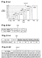
- FIG. 2(a) An example of the machining processes included in the basic machining program GPR is shown in Fig. 2(a).
- cutting tools numbered T1 to T10 are employed.
- the cutting tools T1 to T10 sequentially perform machining processes KK1 to KK10, respectively.
- the simulation result information KJ includes machining time data SJ, which indicates the initiating time and terminating time of each machining process. Accordingly, the information shown on the display 6 includes the machining time data SJ, which is displayed as a graph like that shown in Fig. 2(a).
- the simulation result information KJ includes values of machining variables HJ, which indicates the state of the spindle and tool in each machining step KK1 to KK10.
- the values of machining variables HJ may be in the form of a table, such as that shown in Fig. 2(d), indicating the maximum spindle load, the tool cutting speed, and the spindle rotating speed, in correspondence with each cutting tool number T1 to T10.
- the maximum spindle load indicates the maximum value of the torque load acting on the spindle during machining relative to the tolerated maximum torque load of the spindle.
- the spindle rotating speed is indicated as rotating speed per minute.
- machining navigation command C1 Upon completion of the machining simulation, the operator inputs a machining navigation command C1 with the keyboard 5.
- the main controller 3 receives the command C1 and executes machining navigation with the machining navigator 15.
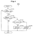
- the machining navigator 15 reads out a navigation program NPR (Fig. 3), which is stored in the system program memory 16, to execute the machining navigation.
- the machining navigation is a programming aiding process in which specific advice is given to the operator on how to improve the basic machining program GPR.
- the machining navigator 15 commands the display controller 13 to generate a message on the display 6 demanding the designation of the machining process that is to be subjected to machining navigation.
- the operator designates the subject machining process by inputting the number of the cutting tool used in that process.
- the operator refers to the machining time data SJ to locate the machining process that should undergo machining navigation. For example, the operator selects the machining process for which the machining time is relatively long. The operator then inputs the number assigned to the cutting tool used in the selected machining process with the keyboard 5. For example, in Fig. 2(a), the machining time of machining processes KK2, KK5, KK8, and KK10 are relatively long. In this case, the operator inputs the corresponding tool numbers T2, T5, T8, and T10 with the keyboard 5.
- the tool number determiner 17 determines whether or not the tool numbers have been input. If the tool numbers T2, T5, T8, T10 are determined to have been input, the determiner 17 outputs an input completion signal S1.
- the machining navigator 15 stores the input tool numbers T2, T5, T8, T10 in a tool number memory 19.
- the tool number memory 19 includes a processing table STB that assigns a sequential processing ordinal number (1st, 2nd, 3rd, and so forth) to each tool.
- the machining navigator 15 sets an ordinal variable i, which is stored in the variable memory 20, to an initial value of 1.
- the ordinal variable i represents the order of a given tool that undergoes machining navigation.
- the machining navigator 15 commands the sub-routine number selector 21 to select the number of a sub-routine (described later).
- the sub-routine number selector 21 first commands the subject tool determiner 27 to determine the type of the subject cutting tool.
- the subject tool determiner 27 refers to the processing table STB (Fig. 2(b)), which is stored in the tool number memory 19, according to the current value of the ordinal variable i, which is stored in the variable memory 20. For example, if the variable i indicates the initial value of 1, the tool that is to be used first in the processing table STB of Fig. 2(b) is selected. In this case, the tool number assigned to ordinal number 1 is T2. Thus, the subject tool determiner 27 selects tool number T2 and stores the selected number in the subject tool number memory 29. Furthermore, the subject tool determiner 27 determines the type of the cutting tool corresponding to the selected tool number by referring to the tool data file KDF, which is stored in the tool data memory 9.
- the sub-routine memory 22 stores a sub-routine number table VTB, which indicates a sub-routine number corresponding to each type of cutting tool, as shown in Fig. 2(c).
- a sub-routine number table VTB which indicates a sub-routine number corresponding to each type of cutting tool, as shown in Fig. 2(c).
- four sub-routine numbers 61, 62, 63, 64 are assigned to five types of cutting tools.
- the four sub-routines 61, 62, 63, 64 are associated with first, second, third, and fourth sub-routines SR61, SR62, SR63, SR64, illustrated in Figs. 4, 5, 6, and 7, respectively.
- the sub-routine number selector 21 refers to the sub-routine number table VTB to select the sub-routine number assigned to the determined cutting tool type. For example, if the cutting tool assigned to the selected tool number T2 is a drill, the sub-routine number selector 21 selects sub-routine number 61 from the sub-routine number table VTB of Fig. 2(c).
- the selection determiner 23 determines whether or not the sub-routine number selector 21 has selected a sub-routine number. If it is determined that a sub-routine number has been selected, the selection determiner 23 outputs a selection completion signal S2. When the selection completion signal S2 is output, at step ST7, the machining navigator 15 executes the sub-routine that has the selected sub-routine number. For example, if the selected sub-routine number is 61, the first sub-routine SR61, shown in Fig. 4, is executed. Afterward, step ST8, which is described later, is carried out upon completion of the execution of the sub-routine.
- the selection determiner 23 outputs a non-selection signal S3.
- the sub-routine number selector 21 cannot select a sub-routine number since the sub-routine number table VTB of Fig. 2(c) does not include these tool types.
- the non-selection signal S3 is output, none of the sub-routines is carried out. In such case, the machining navigation proceeds to step ST8. In other words, machining processes performed by cutting tools that are not included in the sub-routine number table VTB of Fig. 2(c) are not subject to machining navigation.
- the processing completion determiner 26 judges whether or not the ordinal variable i stored in the variable memory 20 has reached a maximum value i max .
- the ordinal number i assigned to the four tool numbers T2, T5, T8, and T10 is 1, 2, 3, and 4, respectively.
- the maximum value i max of the ordinal variable i is 4. If the processing completion determiner 26 determines that the ordinal variable i has not reached the maximum value i max , step ST9 is performed. In step ST9, the machining navigator 15 adds one to the variable i in an incremental manner. Afterward, the processing returns to step ST5.
- the processing completion determiner 26 determines that the ordinal variable i has reached the maximum value i max , the machining navigator 15 terminates the navigation program NPR.
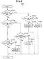
- the first sub-routine SR61 which is illustrated in Fig. 4, is executed when the cutting tool is a drill.
- the machining navigator 15 commands the tool diameter determiner 40 to determine the diameter of the selected cutting tool.
- the tool diameter determiner 40 refers to the tool data file KDF, which is stored in the tool data memory 9, to determine the diameter of the current subject tool.
- the tool whose number is currently stored in the subject tool number memory 29 is the current subject tool.
- the tool diameter determiner 40 judges whether or not the diameter of the subject tool is equal to or greater than a predetermined value (3mm in Fig. 4).
- the machining navigator 15 terminates the sub-routine without executing the machining navigation.
- the spindle load determiner 41 determines the load applied to the spindle. More specifically, the spindle load determiner 41 refers to the values of machining variables HJ (Fig. 2(d)) to determine the maximum load applied to the spindle (maximum spindle load) by the cutting tool assigned to the tool number currently stored in the subject tool number memory 29. The spindle load determiner 41 then judges whether or not the maximum spindle load is equal to or lower than a predetermined limit value SF.
- the limit value SF is one of the parameters used to determine the machining efficiency and may be set, for example, at 80%. Furthermore, the limit value SF may be changed arbitrarily before executing the navigation program NPR.
- the machining navigator 15 terminates the sub-routine without executing the machining navigation. If the maximum spindle load is equal to or smaller than the limit value SF, the spindle load can be further increased. Thus, the machining navigator 15 proceeds to step ST103.
- the sub-routine proceeds to step ST103.
- the cutting speed determiner 42 determines the cutting speed of the subject cutting tool. More specifically, the cutting speed determiner 42 refers to the values of machining variables HJ (Fig. 2(d)) to determine the cutting speed of the tool assigned to the tool number stored in the subject tool number memory 29. The cutting speed determiner 42 then judges whether or not the cutting speed is equal to or lower than a limit value WJ, which is computed by the limit value calculator 46.
- the limit value WJ is also one of the parameters used to determine the machining efficiency.
- the limit value calculator 46 refers to the first basic cutting speed file SYF1, which is illustrated in Fig. 9(a) and stored in the basic cutting speed file memory 43, and a first compensation coefficient file SKF1, which is illustrated in Fig. 9(b) and stored in the compensation coefficient file memory 45, to compute the cutting speed limit value WJ.
- the first basic cutting speed file SYF1, shown in Fig. 9(a), and the first compensation coefficient file SKF1, shown in Fig. 9(b), are used for drills.
- the first basic cutting speed file SYF1 indicates the cutting speed limit value of the cutting tool (drill) for different types of workpiece materials.
- the first compensation coefficient file SKF1 includes a plurality of tables ta1, ta2, ta3, and so forth. Each table corresponds to one of the workpiece materials listed in the first basic cutting speed file SYF1. Each table indicates the compensation coefficient for different types of cutting tool materials.
- the compensation coefficient is used to compensate the basic cutting speed of the workpiece material listed in the first basic cutting speed file SYF1.
- Each table of the first compensation coefficient file SKF1 lists not only cutting tool materials but also the structure or usage of the cutting tool.
- HSS high-speed steel
- carbide refer to tool tip materials.
- Coolant through refers to the tool structure and indicates tools having passages through which coolant flows.
- Throw away refers to the tool usage and indicates disposable tools.
- the calculator 46 refers to the basic machining program GPR stored in the machining program memory 10 to determine the material of the subject workpiece.
- the calculator 46 also refers to the cutting tool data file KDF in the cutting tool data memory 9 to determine the material of the cutting tool assigned with the tool number stored in the subject tool number memory 29.
- the calculator 46 selects the basic cutting speed that corresponds to the material of the workpiece from the first basic cutting speed file SYF1 of Fig. 9(a).
- the calculator 46 further selects the table corresponding to the subject workpiece material from the first compensation coefficient file SKF1 of Fig. 9(b) to locate the compensation coefficient corresponding to the tool material.
- the calculator 46 then multiplies the selected basic cutting speed with the selected compensation coefficient to obtain the cutting speed limit value WJ of the subject cutting tool (drill). Accordingly, the type and material of the cutting tool (drill) used for machining and the material of the subject workpiece are taken into consideration when computing the limit value WJ.
- the basic cutting speed corresponding to FC is 30m/min as shown in the first basic cutting speed file SYF1 of Fig. 9(a). It is also assumed here that the workpiece material corresponding to table ta1 of the first compensation coefficient file SKF1 of Fig. 9(b) is FC. Since the material of the drill is carbide, the corresponding compensation coefficient is 220%, as shown in table ta1. Accordingly, the cutting speed limit value WJ is 66m/min. Other factors such as the tool diameter, the cutting width, the cutting depth, the workpiece rigidity, and how the cutting tool is attached to the spindle may also be taken into consideration when computing the limit value WJ.
- the cutting speed determiner 42 judges whether or not the cutting speed of the drill is equal to or lower than the limit value WJ. If the cutting speed is higher than the limit value WJ, step ST104 is carried out. If the cutting speed is equal to or lower than the limit value WJ, step ST105 is carried out. At steps ST104 and ST105, the navigation information manager 49 reads out predetermined navigation information from the navigation information memory 47 and displays the information on the display 6.
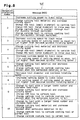
- the navigation information memory 47 stores navigation information NJF such as that shown in Fig. 8.
- the navigation data NJF includes 10 messages MSG, each assigned with a different navigation information number of 1 to 10.
- the table of Fig. 8 lists exemplary messages. Thus, the messages are not limited to those of Fig. 8 and may be changed as required.
- the messages MSG show specific advice for improving the basic machining program GPR to perform faster machining and to improve the machining efficiency.
- step ST103 If it is determined that the cutting speed of the tool is higher than the cutting speed limit value WJ in step ST103, this indicates that the spindle load may still be increased (step ST102). However, the cutting speed of the tool, which has been designated in the basic machining program GPR, cannot be increased since it has already exceeded the limit value WJ. In such case, the sub-routine proceeds to step ST104.
- the navigation information manager 49 reads out the message MSG designated as navigation information number 2 from the navigation information memory 47 and transmits the message MSG to the display controller 13. The display controller 13 then displays the received message MSG on the display 6.
- the message MSG assigned with number 2 advises changing the cutting tool material so that the cutting speed may be increased.
- a change in the material of the cutting tool changes the compensation coefficient that is selected from the first compensation coefficient file SKF1. Accordingly, if the cutting tool material is changed to obtain a larger compensation coefficient, the cutting speed limit value WJ is increased. Since this permits an increase in the cutting tool speed, faster machining can be performed.
- the material of the drill is designated as carbide, while the workpiece material is designated as FC in the basic machining program GPR.
- the compensation coefficient is determined to be 220% from table ta1 of the first compensation coefficient SKF1 shown in Fig. 9(b).
- the message MSG designated as number 2 appears on the display 6 so that the operator can acknowledge that the cutting speed may be increased if the carbide drill is changed to a coolant through type drill (assuming that the spindle has a coolant passage for permitting the flow of coolant into the cutting tool).
- the compensation coefficient is 460% as shown in table ta1 of the first compensation coefficient SKF1 (Fig. 9(b)).
- the message MSG (number 2) that appears on the display 6 advises the operator to change the cutting tool material so that the cutting speed can be increased.
- the operator can improve the cutting conditions of the subject machining process in the basic machining program GPR (in this case, the cutting tool material) by changing the cutting tool material.
- Correction of the machining program PRO increases the cutting speed limit value WJ. Therefore, the cutting speed may be increased within the range of the load tolerated by the spindle.
- the navigation apparatus 2 advises the operator on how the machining program can be improved by displaying a message MSG on the display 6.
- the operator can easily make a machining program that permits high speed and efficient machining just by following the advise given by the navigation apparatus 2.
- step ST105 the navigation information manager 49 reads out the message MSG that corresponds to navigation information number 1 from the navigation information memory 47 and transmits the message MSG to the display controller 13. The display controller 13 then displays the received message MSG on the display 6.
- the message MSG designated as number 1 indicates that the cutting speed may be increased to the limit value.
- the limit value WJ which is computed by the calculator 46, be shown on the display 6 in addition to the message MSG (number 1). Accordingly, the operator can easily determine the extent to which the cutting speed of the subject cutting tool may be increased.
- the message MSG (number 1) that appears on the display 6 advises the operator to increase the cutting speed within the range defined by the limit value WJ. Accordingly, upon completion of the navigation program NPR, the operator can improve the cutting conditions of the subject machining process in the basic machining program GPR by increasing the cutting speed. Correction of the machining program PRO increases the cutting speed in the subject machining process. Thus, machining is performed with high speed and high efficiency.
- the first sub-routine SR61 is completed when either step ST104 or step ST105 is finished.
- the spindle load determiner 41 determines the load applied to the spindle. More specifically, the spindle load determiner 41 judges whether or not the maximum load applied to the spindle (maximum spindle load) by the cutting tool designated by the tool number stored in the subject tool number memory 29 is equal to or lower than a predetermined limit value SF (e.g., 80%). If the maximum spindle load is greater than the limit value SF, step ST202 is carried out.
- a predetermined limit value SF e.g., 80%
- the values of machining variables HJ indicates that the maximum spindle load of the tool is 81%. If the limit value SF is 80%, the maximum spindle load is greater than the limit value SF. In this case, the sub-routine SR62 proceeds to step ST202.
- the cutting speed determiner 42 refers to the values of machining variables HJ (Fig. 2(d)) to determine the cutting speed of the end mill, the tool number of which is stored in the subject tool number memory 29. The cutting speed determiner 42 then judges whether or not the cutting speed of the end mill is equal to or lower than the limit value WJ, which is computed by the calculator 46.
- the calculator 46 refers to the second basic cutting speed file SYF2, which is illustrated in Fig. 10(a) and stored in the basic cutting speed file memory 43, and the second compensation coefficient file SKF2, which is illustrated in Fig. 10(b) and stored in the compensation coefficient file memory 45, to compute the cutting speed limit value WJ.
- the second basic cutting speed file SYF2 of Fig. 10(a) and the second compensation coefficient file SKF2 of Fig. 10(b) are referred to when the cutting tool is an end mill.
- the second basic cutting speed file SYF2 indicates the cutting speed limit value of the cutting tool (end mill) for different types of workpiece materials.
- the second compensation coefficient file SKF2 includes a plurality of tables td1, td2, td3, and so forth. Each table corresponds to one of the workpiece materials listed in the second basic cutting speed file SYF2. Each table indicates the compensation coefficient for different types of cutting tool materials. The compensation coefficient is used to compensate the basic cutting speed of the workpiece material listed in the second basic cutting speed file SYF2.
- the second compensation coefficient file SKF2 lists not only cutting tool materials but also the structure or usage of the cutting tool.
- the calculator 46 refers to the basic machining program GPR stored in the machining program memory 10 to determine the material of the subject workpiece.
- the calculator 46 also refers to the cutting tool data file KDF in the cutting tool data memory 9 to determine the material of the cutting tool designated by the tool number stored in the subject tool number memory 29.
- the calculator 46 selects the basic cutting speed that corresponds to the material of the workpiece from the second basic cutting speed file SYF2 of Fig. 10(a).
- the calculator 46 further selects the table corresponding to the subject workpiece material from the second compensation coefficient file SKF2 of Fig. 10(b) to locate the compensation coefficient corresponding to the tool material.
- the calculator 46 then multiplies the selected basic cutting speed with the selected compensation coefficient to obtain the cutting speed limit value WJ of the subject cutting tool (end mill).
- the cutting speed determiner 42 judges whether or not the cutting speed of the subject cutting tool is equal to or lower than the computed limit value WJ. If the cutting speed is higher than the limit value WJ, the sub-routine SR62 proceeds to step ST203.
- the rotating speed determiner 50 determines the spindle rotating speed. More specifically, the rotating speed determiner 50 refers to the values of machining variables HJ (Fig. 2(d)) stored in a simulation result data memory 12a to determine the spindle rotating speed of the cutting tool designated by the number stored in the subject tool number memory 29. The rotating speed determiner 50 determines whether the spindle rotating speed is equal to or lower than a predetermined base value CH.
- the base value CH is one of the parameters used to judge machining efficiency.
- the output of the spindle becomes maximum and is maintained at a constant value.
- the maximum output of the spindle increases as the spindle rotating speed increases until the spindle rotating speed reaches the base value CH. Accordingly, if the spindle rotating speed is equal to or lower than the base value CH, the output of the spindle can still be increased.
- step ST203 If it is determined that the spindle rotating speed is higher than the base value CH in step ST203, this indicates that the spindle load cannot be increased (step ST201), the cutting speed cannot be further decreased (step ST202), and that the maximum output of the spindle cannot be increased even if the spindle rotating speed is further increased. In such case, the efficiency of the machining process cannot be further improved. Thus, the sub-routine is terminated without executing the machining navigation.
- step ST204 the navigation information manager 49 reads out the message MSG that corresponds to navigation information number 4 from the navigation information memory 47 and transmits the message MSG to the display controller 13. The display controller 13 then displays the received message MSG on the display 6.
- step ST204 is finished, the sub-routine is terminated.
- the message MSG assigned with number 4 advises the operator to change the material of the cutting tool to increase the cutting speed.
- a change in the material of the cutting tool changes the compensation coefficient that is selected from the second compensation coefficient file SKF2. Accordingly, if the cutting tool material is changed to obtain a larger compensation coefficient, the cutting speed limit value WJ is increased. This permits an increase in the spindle rotating speed and the cutting tool speed. An increase in the spindle rotating speed increases the maximum output of the spindle. In such state, the spindle load can be increased. The cutting speed of the tool can be increased as long as the spindle load does not exceed the value stored in the values of machining variables HJ (Fig. 2(d)).
- the compensation coefficient is 25%.
- the message MSG designated as number 4 appears on the display 6, the operator is notified that the cutting speed may be increased by changing the HSS end mill to a carbide end mill. If a carbide end mill is used, the compensation coefficient is 100%, as shown in table td1 of the second compensation coefficient SKF2 (Fig. 10(b)).
- the operator can improve the cutting conditions of the subject machining process in the basic machining program GPR by increasing the cutting speed.
- Correction of the basic machining program GPR further corrects the machining program PRO and increases the cutting speed limit value WJ in the subject machining process.
- the cutting speed is increased within the extent permitted by the maximum output of the spindle.
- step ST205 is carried out.
- the rotating speed determiner 50 judges whether or not the spindle rotating speed is equal to or lower than the base value CH. If the spindle rotating speed is higher than the base value CH, the spindle load cannot be increased and the spindle output cannot be increased, although the cutting speed can. In other words, since the maximum output of the spindle cannot be increased even if the spindle rotating speed is increased, the spindle load cannot be increased. In such case, the efficiency of the subject machining process cannot be improved. Thus, the sub-routine is terminated without executing the machining navigation.
- step ST205 If it is determined that the spindle rotating speed is equal to or lower than the base value CH in step ST205, the spindle load cannot be decreased, but the cutting speed and the spindle output may be increased. In other words, the spindle load may be increased if the maximum output of the spindle is increased by increasing the spindle rotating speed.
- the navigation information manager 49 reads out the message MSG that corresponds to navigation information number 3 from the navigation information memory 47 and transmits the message MSG to the display controller 13. The display controller 13 then displays the received message MSG on the display 6.
- step ST206 is finished, the sub-routine is terminated.
- the message MSG designated as number 3 indicates that the cutting speed of the subject cutting tool may be increased to the limit value WJ. Accordingly, if the message MSG (number 3) appears on the display 6, the operator is notified that the cutting speed may be increased without changing the cutting tool.
- the operator can improve the cutting conditions of the subject machining process in the basic machining program GPR by increasing the cutting speed within the range defined by the limit value WJ in accordance to the message MSG (number 3) shown on the display 6.
- Correction of the basic machining program GPR further corrects the machining program PRO and increases the cutting speed in the subject machining process.
- the cutting speed of the tool can be increased as long as the spindle load does not exceed the value stored in the values of machining variables HJ (Fig. 2(d)).
- step ST207 is performed.
- the cutting speed determiner 42 determines the cutting speed of the subject cutting tool in the same manner as step ST202. If the cutting speed is higher than the limit value WJ, the spindle load can be increased but the cutting speed cannot.
- the navigation information manager 49 reads out the message MSG that corresponds to navigation information number 4 from the navigation information memory 47 and transmits the message MSG to the display controller 13. The display controller 13 then displays the received message MSG on the display 6.
- step ST208 is finished, the sub-routine is terminated.
- the message MSG designated as number 4 advises changing the cutting tool material so that the cutting speed may be increased.
- a change in the material of the cutting tool changes the compensation coefficient that is selected from the third compensation coefficient file SKF3. Therefore, if the cutting tool material is changed to obtain a larger compensation coefficient, the cutting speed limit value WJ is increased, which permits a higher cutting speed.
- the operator can improve the cutting conditions of the subject machining process in the basic machining program GPR by increasing the cutting speed within the range defined by the limit value WJ.
- Correction of the machining program PRO increases the cutting speed limit value WJ in the subject machining process and the cutting speed accordingly.
- step ST207 if the cutting speed is equal to or lower than the limit value WJ, the spindle load and the cutting speed can both be increased.
- step ST209 in the same manner as step ST206, the navigation information manager 49 reads out the message MSG that corresponds to navigation information number 3 from the navigation information memory 47 and transmits the message MSG to the display controller 13. The display controller 13 then displays the received message MSG on the display 6.
- step ST209 is finished, the sub-routine is terminated.
- the message MSG assigned to number 3 indicates that the cutting speed of the subject cutting tool may be increased to the limit value WJ. Therefore, if the message MSG (number 3) appears on the display 6, the operator is notified that the cutting speed may be increased without changing the cutting tool.
- the operator can improve the cutting conditions of the subject machining process in the basic machining program GPR in accordance with the message MSG (number 3) shown on the display 6 by increasing the cutting speed within the range defined by the limit value WJ. Accordingly, correction of the basic machining program GPR further corrects the machining program PRO and increases the cutting speed in the subject machining process.
- the spindle load determiner 41 determines the load applied to the spindle. More specifically, the spindle load determiner 41 judges whether or not the maximum load applied to the spindle (maximum spindle load) by the cutting tool designated with the tool number stored in the subject tool number memory 29 is equal to or lower than a predetermined limit value SF (e.g., 80%). If the maximum spindle load is greater than the limit value SF, step ST302 is carried out.
- a predetermined limit value SF e.g., 80%
- the cutting speed determiner 42 determines the cutting speed of the subject cutting tool. That is, the cutting speed determiner 42 refers to the values of machining variables HJ (Fig. 2(d)) to determine the cutting speed of the cutting tool designated by the number stored in the subject tool number memory 29. The cutting speed determiner 42 then judges whether or not the cutting speed is equal to or lower than the limit value WJ, which is computed by the limit value calculator 46.
- the limit value calculator 46 refers to the third basic cutting speed file SYF3, which is illustrated in Fig. 11(a) and stored in the basic cutting speed file memory 43, and a third compensation coefficient file SKF3, which is illustrated in Fig. 11(b) and stored in the compensation coefficient file memory 45, to compute the cutting speed limit value WJ.
- the third basic cutting speed file SYF3 of Fig. 11(a) and the third compensation coefficient file SKF3 of Fig. 11(b) are used for face mills.
- the third basic cutting speed file SYF3 indicates the cutting speed limit value of the cutting tool (face mill) for different types of workpiece materials.
- the third compensation coefficient file SKF3 includes a plurality of tables tf1, tf2, tf3, and so forth. Each table corresponds to one of the workpiece materials listed in the third basic cutting speed file SYF3. Each table indicates the compensation coefficient for different types of cutting tool materials.
- the third compensation coefficient file SKF3 lists not only cutting tool materials but also the structure or usage of the cutting tool.
- the calculator 46 refers to the basic machining program GPR stored in the machining program memory 10 to determine the material of the subject workpiece.
- the calculator 46 also refers to the cutting tool data file KDF in the cutting tool data memory 9 to determine the material of the cutting tool designated by the tool number stored in the subject tool number memory 29.
- the calculator 46 selects the basic cutting speed that corresponds to the material of the workpiece from the third basic cutting speed file SYF3 of Fig. 11(a).
- the calculator 46 further selects the table corresponding to the subject workpiece material from the third compensation coefficient file SKF3 of Fig. 11(b) to locate the compensation coefficient corresponding to the tool material.
- the calculator 46 then multiplies the selected basic cutting speed with the selected compensation coefficient to obtain the cutting speed limit value WJ of the subject cutting tool (end mill).
- step ST303 is carried out.
- the rotating speed determiner 50 determines the spindle rotating speed. More specifically, the rotating speed determiner 50 judges whether or not the spindle rotating speed of the cutting tool designated by the tool number stored in the subject tool number memory 29 is equal to or lower than a predetermined base value CH.
- step ST301 If the spindle rotating speed is higher than the base value CH, this indicates that the spindle load cannot be increased (step ST301) and that the cutting spindle cannot be increased (step ST302). In addition, the spindle output cannot be increased. In such case, the efficiency of the subject machining process cannot be increased. Thus, the sub-routine is terminated without executing the machining navigation.
- step ST304 the navigation information manager 49 reads out the message MSG that corresponds to navigation information number 6 from the navigation information memory 47 and transmits the message MSG to the display controller 13. The display controller 13 then displays the received message MSG on the display 6.
- step ST304 is finished, the sub-routine is terminated.
- the message MSG assigned with number 6 advises the operator to change the material of the cutting tool to increase the cutting speed.
- a change in the material of the cutting tool changes the compensation coefficient that is determined by referring to the second compensation coefficient file SKF2. Accordingly, if the cutting tool material is changed to obtain a larger compensation coefficient, the cutting speed limit value WJ is increased. This permits an increase in the spindle rotating speed and the cutting tool speed. An increase in the spindle rotating speed increases the maximum output of the spindle. In such state, the spindle load can be increased.
- the compensation coefficient is 100%.
- the compensation coefficient is 115%, as shown in table tf1 of the third compensation coefficient SKF3 (Fig. 10(b)).
- the operator can improve the cutting conditions of the subject machining process in the basic machining program GPR by increasing the cutting speed in accordance with the number 6 message MSG shown on the display 6.
- Correction of the basic machining program GPR further corrects the machining program PRO such that the cutting speed limit value WJ increases.
- the cutting speed is increased within the extent permitted by the maximum output of the spindle.
- step ST305 is carried out.
- the rotating speed determiner 50 judges whether or not the spindle rotating speed is equal to or lower than the base value CH. If the spindle rotating speed is higher than the base value CH, the spindle load cannot be increased and that the spindle output cannot be increased, although the cutting speed can. In other words, since the maximum output of the spindle cannot be increased even if the spindle rotating speed is increased, the spindle load cannot be increased. In such case, the efficiency of the subject machining process cannot be improved. Thus, the sub-routine is terminated without executing the machining navigation.
- step ST305 If it is determined that the spindle rotating speed is equal to or lower than the base value CH in step ST305, the spindle load cannot be decreased, but the cutting speed and the spindle output may be increased. In other words, the spindle load may be increased if the maximum output of the spindle is increased by increasing the spindle rotating speed.
- the navigation information manager 49 reads out the message MSG that corresponds to navigation information number 5 from the navigation information memory 47 and transmits the message MSG to the display controller 13. The display controller 13 then displays the received message MSG on the display 6.
- step ST306 is finished, the sub-routine is terminated.
- the message MSG assigned to number 5 advises that the cutting speed of the subject cutting tool may be increased to the limit value WJ. Accordingly, if the message MSG (number 5) appears on the display 6, the operator is notified that the cutting speed may be increased without changing the cutting tool.
- the operator can improve the cutting conditions of the subject machining process in the basic machining program GPR by increasing the cutting speed within the range permitted by the limit value WJ in accordance to the message MSG (number 5) shown on the display 6. Correction of the basic machining program GPR further corrects the machining program PRO and increases the cutting speed in the subject machining process.
- step ST307 is performed.
- the cutting speed determiner 42 determines the cutting speed of the subject cutting tool in the same manner as step ST302. If the cutting speed is higher than the limit value WJ, at step ST308, in the same manner as steps ST303 and ST305, the rotating speed determiner 50 judges whether or not the spindle rotating speed is equal to or lower than the base value CH. If the spindle rotating speed is higher than the base value CH, the spindle load can be increased, but the cutting speed and the spindle output cannot. In this case, efficiency of the subject machining process cannot be improved. Thus, the sub-routine is terminated without executing the machining navigation.
- step ST309 the navigation information manager 49 reads out the message MSG that corresponds to navigation information number 7 from the navigation information memory 47 and transmits the message MSG to the display controller 13. The display controller 13 then displays the received message MSG on the display 6.
- step ST309 the sub-routine is terminated.
- the message MSG designated by number 7 advises using a face mill with a smaller diameter so that the spindle rotating speed can be increased.
- the employment of a face mill with a smaller diameter increases the spindle rotating speed without increasing the cutting speed. If the spindle rotating speed increases, the maximum output of the spindle increases. This allows an increase in the spindle load.
- the operator can improve the cutting conditions of the subject machining process in the basic machining program GPR by using a face mill with a smaller diameter such that the spindle rotating speed reaches the base value CH in accordance to the message MSG (number 7) shown on the display 6.
- Correction of the basic machining program GPR further corrects the machining program PRO and increases spindle rotating speed without increasing the cutting speed in the subject machining process. Thus, high speed and efficient machining is performed.
- step ST310 in the same manner as step ST306, the navigation information manager 49 reads out the message MSG that corresponds to navigation information number 5 from the navigation information memory 47 and transmits the message MSG to the display controller 13. The display controller 13 then displays the received message MSG on the display 6.
- step ST310 is finished, the sub-routine is terminated.
- the message MSG designated as number 5 advises that the cutting speed of the subject cutting tool may be increased to the limit value WJ. Accordingly, if the message MSG (number 5) appears on the display 6, the operator is notified that the cutting speed may be increased without changing the cutting tool.
- the operator can improve the cutting conditions of the subject machining process in the basic machining program GPR by increasing the cutting speed within the range permitted by the limit value WJ in accordance to the message MSG (number 5) shown on the display 6. Correction of the basic machining program GPR further corrects the machining program PRO and increases the cutting speed in the subject machining process. Thus, high speed and efficient machining is performed.
- the fourth sub-routine SR64 is executed when the subject cutting tool is an end mill or a face mill that are used for finish machining.
- the cutting speed determiner 42 determines the cutting speed of the subject cutting tool. That is, the cutting speed determiner 42 refers to the values of machining variables HJ (Fig. 2(d)) to determine the cutting speed of the cutting tool designated by the number stored in the subject tool number memory 29. The cutting speed determiner 42 then judges whether or not the cutting speed of the subject cutting tool is equal to or lower than the limit value WJ, which is computed by the limit value calculator 46.
- the limit value calculator 46 refers to the second basic cutting speed file SYF2 of Fig. 10(a) and the second compensation coefficient file SKF2 of Fig. 10(b) to compute the limit value WJ. Since the computation using the files SYF3, SKF3 is the same as that performed in step ST202 of the second sub-routine SR62, the computation will not be described here.
- step ST402 the navigation information manager 49 reads out the message MSG that corresponds to navigation information number 9 from the navigation information memory 47 and transmits the message MSG to the display controller 13. The display controller 13 then displays the received message MSG on the display 6.
- step ST402 the sub-routine is terminated.
- the message MSG assigned to number 9 advises to change the material of the cutting tool such that the cutting speed may be increased, and to use a cutting tool that has a larger number of teeth such that the cutting feed rate may be increased.
- high speed machining can be performed by changing the material of the end mill to one having a higher cutting speed limit value WJ to increase the cutting speed and by using an end mill having a larger number of teeth to increase the feed rate.
- the operator can improve the cutting conditions of the subject machining process in the basic machining program GPR in accordance with the message MSG (number 9) shown on the display 6 by changing the material of the end mill to increase the cutting speed and by using an end mill having a larger number of teeth to increase the feed rate.
- Correction of the basic machining program GPR further corrects the machining program PRO and increases the cutting speed and the feed rate in the subject machining process. Thus, high speed and efficient machining is performed.
- the limit value calculator 46 refers to the third basic cutting speed file SYF3 of Fig. 11(a) and the third compensation coefficient file SKF3 of Fig. 11(b) to compute the limit value WJ. Since the computation using the files SYF3, SKF3 is the same as that performed in step ST302 of the third sub-routine SR63, the computation will not be described here.
- the navigation information manager 49 reads out the message MSG that corresponds to navigation information number 10 from the navigation information memory 47 and transmits the message MSG to the display controller 13. The display controller 13 then displays the received message MSG on the display 6.
- the message MSG assigned to number 10 advises changing the material of the cutting tool such that the cutting speed may be increased and to use a cutting tool that has a larger number of teeth such that the cutting feed rate may be increased. Accordingly, upon completion of the navigation program NPR, the operator can improve the cutting conditions of the subject machining process in the basic machining program GPR in accordance with the message MSG (number 10) shown on the display 6 by changing the material of the face mill to increase the cutting speed and by using a face mill having a larger number of teeth to increase the feed rate. Correction of the basic machining program GPR further corrects the machining program PRO and increases the cutting speed and the feed rate in the subject machining process. Thus, high speed and efficient machining is performed.
- step ST403 is carried out.
- the navigation information manager 49 reads out the message MSG that corresponds to navigation information number 8 from the navigation information memory 47 and transmits the message MSG to the display controller 13.
- the display controller 13 displays the received message MSG on the display 6.
- the message MSG assigned to number 8 indicates that the cutting speed of the cutting tool may be increased to the limit value WJ. Therefore, if the message MSG (number 8) appears on the display 6, the operator is notified that the cutting speed may be increased without changing the cutting tool.
- the operator can improve the cutting conditions of the subject machining process in the basic machining program GPR in accordance with the message MSG (number 8) shown on the display 6 by increasing the cutting speed within the range permitted by the limit value WJ. Accordingly, correction of the basic machining program GPR further corrects the machining program PRO and increases the cutting speed in the subject machining process. Thus, high speed and efficient machining is performed.
- the operator designates a machining process which machining efficiency should be improved.
- the machining navigation apparatus 2 then advises the operator on how the subject machining process should be improved by displaying navigation information, which are illustrated in Fig. 8, on the display 6. Accordingly, if the operator follows the advice given by the navigation information and improves the cutting conditions of the subject machining process in the basic machining program GPR accordingly, the operator can easily make the final machining program PRO without special knowledge or experience.
- the actual machining is performed in accordance with the final machining program PRO, which is stored in the machining program memory 10.
- the final machining program PRO is improved so that machining is performed at the highest speed allowed by the capacity of the spindle motor and the cutting tool. Therefore, high speed and efficient machining is performed by using the machining program PRO in comparison to when using the uncorrected basic machining program GPR.
- the machining navigation apparatus 2 facilitates the correction of machining programs made for conventional machining tools to adapt to new machining tools having increased spindle capacities or using new types of tools. Therefore, machining programs are always adapted to updated machining tools by the machining navigation apparatus 2. Since the outdating of programs is avoided, software is used continuously and efficiently.
- Machining navigation is performed only on the machining processes selected from the machining program. In other words, the machining navigation is performed only on machining processes which machining efficiency the operator wishes to improve. This avoids unnecessary processing and saves time.
- the machining navigation can be performed in accordance with the values of machining variables HJ, which is obtained by executing the machining simulation. Accordingly, since actual machining of the workpiece need not be performed to execute the machining navigation, time is saved.
- the machining navigation is performed once on the subject machining process.
- the machining navigation may be performed twice in the same machining process.
- the navigation program NPR which is illustrated in Fig. 3
- the navigation program NPR may be re-executed to further improve the machining program. If necessary, such processing may be carried out repetitively to further improve the machining program.
- the navigation is performed on a number of machining processes before it stops.
- the machining processes may be designated one at a time so that the machining navigation is executed once for each process.
- the operator refers to the machining time data SJ of Fig. 2(a) that appears on the display 6 to select a single machining process on which the operator wishes to execute the machining navigation.
- the operator designates the number of the cutting tool used in the selected machining process with the keyboard 5.
- the subject tool determiner 27 then refers to the tool data file KDF, which is stored in the tool data memory 9, to determine the type of the tool with the designated number.
- the sub-routine number selector 21 then refers to the sub-routine number table VTB, which is illustrated in Fig. 2(c), to select the number of the sub-routine corresponding to the tool type.
- Execution of the sub-routine results in the display of navigation information, which is related to the machining process.
- the operator then changes the cutting conditions of the subject machining process in accordance with the information on the display 6.
- the operator selects another machining process that should undergo the machining navigation and designates the number of the cutting tool used in that process with the keyboard.
- the selected machining process undergoes the machining navigation and the operator then improves the machining program. This is repeated to perform machining navigation on a number of machining processes to improve the machining program. If necessary, the machining navigation may be executed for the same process repeatedly to correct the machining program more than once to further improve the machining program.
- the machining navigation apparatus 2 is employed to aid the composition of a machining program PRO in a machining center 1.
- the present invention may also be applied to other types of machine tools, such as a lathe, an electric discharge machine, and a laser cutting machine to aid the composition of machining programs.
- the contents and values of the values of machining variables HJ are changed in accordance with the type of machine.
- the values of machining variables HJ may include the spindle rotating speed and the spindle load in lathes, the distance between electrodes and the voltage load in electric discharge machines, and the voltage load in laser cutting machines.
- the parameters that are referred to judge the machining efficiency are changed to parameters corresponding to the machine.
- the machining efficiency may be judges by referring to a spindle load limit value in lathes, and a voltage load limit value in electric discharge machines and laser cutting machines.
- the contents of the navigation information that appears on the display may also be changed in accordance with the machine.
- the machining navigation apparatus 2 is incorporated in the control unit 100 of the machining center 1.
- the machining navigation apparatus may be an apparatus that is independent from the machining center 1 or the control unit 100.
- the machining simulation may be executed by an apparatus separate from the machining navigation apparatus.
- the simulation result information KJ only the values of machining variables HJ of the machining processes, the cutting conditions of which should be corrected, is transmitted to the machining navigation apparatus to execute machining navigation on those processes. Accordingly, the machining navigation apparatus need not store machining programs GPR. Thus, the machining program memory 10 is not necessary.
- a workpiece may actually be machined to perform the machining navigation using the data obtained during the actual machining.
- the message MSG explains, for example, that the cutting speed may be increased to the limit value.
- the message MSG may explain that the cutting speed may be increased to a specific value, which corresponds to the limit value.
- the message MSG may explain that the cutting speed may be increased to (value)m/min.
- specific examples showing how to perform high speed machining may be shown on the display 6.
- the type of cutting tool may be shown together on the display 6 with the cutting conditions, such as the cutting speed and the feed rate.
- the parameters used to judge the machining efficiency are the spindle load limit value SF, the cutting speed limit value WJ, and the spindle speed base value CH.
- any parameter can be used as long as the machining efficiency can be judged.
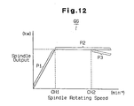
- the spindle rotating speed limit value may be used as a parameter related with the spindle rotating speed. More specifically, as shown in the graph of Fig. 12, the machining navigation apparatus 2 may store a characteristic data QG that shows the relationship between the spindle rotating speed and the spindle output. In this case, during execution of the machining navigation, the machining efficiency is judged from the spindle speed in accordance with the spindle characteristic data QG.
- the spindle output increases as the spindle rotating speed increases.
- This range is denoted as P1.
- the spindle rotating speed can be increased.
- the machining navigation apparatus 2 determines that the machining efficiency can be improved by increasing the spindle rotating speed.
- the spindle rotating speed is equal to or higher than the first base value CH1
- the spindle output remains fixed at a constant maximum value regardless of changes in the spindle rotating speed. This range is denoted as P2.
- the spindle rotating speed is included in range P2
- the spindle output cannot be increased.
- the machining navigation apparatus 2 determines that the machining efficiency cannot be improved by increasing the spindle rotating speed.
- the machining navigation apparatus 2 determines that the machining efficiency can be improved if the spindle rotating speed is decreased to a value lower than the second limit value CH2 (and higher than the first limit value CH1) when in range P3.
- the operator refers to the navigation information shown on the display 6 to improve the machining program.
- peripheral equipments i.e., tool management system, abnormality management system, sensors
- machine tools may automatically improve machining programs.
- the navigation information need not be displayed on the display 6 as words and sentences. In other words, characters, diagrams, images, and voices may be used as long as advice for changing the cutting conditions may be given.
Landscapes
- Engineering & Computer Science (AREA)
- Human Computer Interaction (AREA)
- Manufacturing & Machinery (AREA)
- Physics & Mathematics (AREA)
- General Physics & Mathematics (AREA)
- Automation & Control Theory (AREA)
- Numerical Control (AREA)
Applications Claiming Priority (2)
| Application Number | Priority Date | Filing Date | Title |
|---|---|---|---|
| JP9548098 | 1998-03-24 | ||
| JP09548098A JP3800576B2 (ja) | 1998-03-24 | 1998-03-24 | 加工プログラム作成支援装置 |
Publications (3)
| Publication Number | Publication Date |
|---|---|
| EP0945771A2 EP0945771A2 (en) | 1999-09-29 |
| EP0945771A3 EP0945771A3 (en) | 2001-01-10 |
| EP0945771B1 true EP0945771B1 (en) | 2005-12-14 |
Family
ID=14138791
Family Applications (1)
| Application Number | Title | Priority Date | Filing Date |
|---|---|---|---|
| EP99105616A Expired - Lifetime EP0945771B1 (en) | 1998-03-24 | 1999-03-19 | Apparatus and method for aiding programming |
Country Status (4)
| Country | Link |
|---|---|
| US (1) | US6885984B1 (ja) |
| EP (1) | EP0945771B1 (ja) |
| JP (1) | JP3800576B2 (ja) |
| DE (1) | DE69928852T2 (ja) |
Families Citing this family (19)
| Publication number | Priority date | Publication date | Assignee | Title |
|---|---|---|---|---|
| JP3949689B2 (ja) * | 2002-12-26 | 2007-07-25 | 三菱電機株式会社 | 加工プログラム作成装置 |
| US7761183B2 (en) * | 2006-02-13 | 2010-07-20 | Sullivan Douglas G | Methods and systems for producing numerical control program files for controlling machine tools |
| JP2009193209A (ja) * | 2008-02-13 | 2009-08-27 | Brother Ind Ltd | 数値制御装置及び数値制御装置用制御プログラム |
| US20100030348A1 (en) * | 2008-07-30 | 2010-02-04 | Jerry Gene Scherer | Method and system for integrated control of machine operations |
| US8294403B2 (en) * | 2009-09-04 | 2012-10-23 | Haas Automation, Inc. | Methods and systems for determining and displaying a time to overload of machine tools |
| JP5951200B2 (ja) * | 2010-09-09 | 2016-07-13 | Dmg森精機株式会社 | 加工関連データ処理システム |
| JP6066041B2 (ja) * | 2012-07-17 | 2017-01-25 | 三菱日立パワーシステムズ株式会社 | 加工支援装置および加工支援システム |
| GB2508219A (en) * | 2012-11-26 | 2014-05-28 | Taylor Hobson Ltd | Analysing and machining an optical profile |
| JP6058575B2 (ja) * | 2014-03-19 | 2017-01-11 | 株式会社スギノマシン | ウォータージェット切断方法及びウォータージェット切断装置 |
| JP6140115B2 (ja) | 2014-08-12 | 2017-05-31 | ファナック株式会社 | 加工シミュレーション装置 |
| CN107077118B (zh) * | 2014-09-30 | 2019-12-31 | 株式会社牧野铣床制作所 | 机床的控制装置以及机床 |
| JP6148264B2 (ja) * | 2015-01-29 | 2017-06-14 | ファナック株式会社 | 切削条件を自動で変更する機能を有した工作機械 |
| US10401823B2 (en) | 2016-02-04 | 2019-09-03 | Makino Inc. | Real time machining process monitoring utilizing preprocess simulation |
| JP6353884B2 (ja) * | 2016-10-04 | 2018-07-04 | Dmg森精機株式会社 | 加工条件決定装置及び切削工具選択装置 |
| DE102016224871A1 (de) | 2016-12-13 | 2018-06-14 | MTU Aero Engines AG | Verfahren zum Betreiben einer Mehrachs-Drehmaschine und Mehrachs-Drehmaschine |
| JP6875461B2 (ja) * | 2019-07-05 | 2021-05-26 | 株式会社日立製作所 | 機械加工管理方法及び機械加工管理システム |
| JP7486115B2 (ja) * | 2020-03-12 | 2024-05-17 | 三菱重工業株式会社 | 低靱性加工物切削装置、低靱性加工物製造方法および低靱性加工物製造プログラム |
| DE112021007521T5 (de) * | 2021-06-21 | 2024-04-04 | Fanuc Corporation | Steuervorrichtung |
| CN113741352B (zh) * | 2021-09-22 | 2023-01-06 | 陕西法士特齿轮有限责任公司 | 一种数控自适应控制加工方法、系统、设备及其存储介质 |
Family Cites Families (17)
| Publication number | Priority date | Publication date | Assignee | Title |
|---|---|---|---|---|
| US4199814A (en) * | 1977-10-12 | 1980-04-22 | Digitcom, Inc. | Computer numerical control machine tool |
| US4866635A (en) * | 1987-10-19 | 1989-09-12 | Carnegie Group Inc. | Domain independent shell for building a diagnostic expert system |
| JP2606714B2 (ja) * | 1988-01-25 | 1997-05-07 | ファナック株式会社 | 数値制御装置 |
| US4907164A (en) * | 1988-09-26 | 1990-03-06 | General Electric Company | Automatically optimized NC tool path generation for machining |
| US5495417A (en) * | 1990-08-14 | 1996-02-27 | Kabushiki Kaisha Toshiba | System for automatically producing different semiconductor products in different quantities through a plurality of processes along a production line |
| JP2901353B2 (ja) * | 1990-12-28 | 1999-06-07 | オークマ株式会社 | 数値制御工作機械における加工プログラム編集機能を有する数値制御装置 |
| US5208995A (en) * | 1992-03-27 | 1993-05-11 | Mckendrick Blair T | Fixture gauge and method of manufacturing same |
| US5412583A (en) * | 1993-06-10 | 1995-05-02 | Dynamics Research Corp. | Computer implemented balancer |
| JP3331024B2 (ja) * | 1993-10-13 | 2002-10-07 | ファナック株式会社 | 工具寿命管理方式 |
| US5485390A (en) * | 1993-11-30 | 1996-01-16 | The United States Of America As Represented By The Secrectary Of The Air Force | Inductive-deductive process design for machined parts |
| KR100201020B1 (ko) * | 1994-03-11 | 1999-06-15 | 모리시타 요이찌 | 컴퓨터시뮬레이션부착 nc제어미세가공방법과 이 방법에 사용하는 장치 |
| US5659493A (en) * | 1995-03-03 | 1997-08-19 | Ford Motor Company | Virtual machining techniques for modifying computer models of parts |
| AUPO206596A0 (en) * | 1996-08-30 | 1996-09-26 | Anca Pty Ltd | Tool grinding simulation system |
| DE69637808D1 (de) * | 1996-11-07 | 2009-02-26 | Mori Seiki Seisakusho Yamatoko | Verfahren und vorrichtung zur analyse eines nc-programmes für nc-bearbeitung |
| US6202043B1 (en) * | 1996-11-12 | 2001-03-13 | Invention Machine Corporation | Computer based system for imaging and analyzing a process system and indicating values of specific design changes |
| US5991528A (en) * | 1997-11-05 | 1999-11-23 | Reliance Electric Industrial Company | Expert manufacturing system |
| US6112133A (en) * | 1998-02-27 | 2000-08-29 | Imcs, Inc. | Visual system and method for generating a CNC program for machining parts with planar and curvilinear surfaces |
-
1998
- 1998-03-24 JP JP09548098A patent/JP3800576B2/ja not_active Expired - Lifetime
-
1999
- 1999-03-19 EP EP99105616A patent/EP0945771B1/en not_active Expired - Lifetime
- 1999-03-19 DE DE69928852T patent/DE69928852T2/de not_active Expired - Lifetime
- 1999-03-22 US US09/273,256 patent/US6885984B1/en not_active Expired - Lifetime
Also Published As
| Publication number | Publication date |
|---|---|
| US6885984B1 (en) | 2005-04-26 |
| DE69928852T2 (de) | 2006-08-10 |
| DE69928852D1 (de) | 2006-01-19 |
| JP3800576B2 (ja) | 2006-07-26 |
| JPH11277371A (ja) | 1999-10-12 |
| EP0945771A3 (en) | 2001-01-10 |
| EP0945771A2 (en) | 1999-09-29 |
Similar Documents
| Publication | Publication Date | Title |
|---|---|---|
| EP0945771B1 (en) | Apparatus and method for aiding programming | |
| CN100474189C (zh) | 加工钩型齿螺纹的车丝机循环加工方法 | |
| US20020190032A1 (en) | Method and device for controlling a die-sink erosion machine | |
| US6556886B1 (en) | Method and device for controlling a machine tool, in particular, a die-sink erosion machine | |
| JP4059411B2 (ja) | Nc工作機械の制御装置 | |
| JP2001246534A (ja) | 工具寿命管理方法及び工具寿命管理装置 | |
| US7139635B2 (en) | Multi-system numerical control device | |
| EP0310671B1 (en) | Numerical control method capable of variably setting positioning precision | |
| US5270915A (en) | Apparatus for generating numerical control information based on shaped data for each machining step | |
| JPH0242510A (ja) | 加工情報表示方式 | |
| KR860001679B1 (ko) | 수치제어장치 | |
| JPS62130412A (ja) | 数値制御方法 | |
| JP2798549B2 (ja) | 内径加工工具の自動決定方法 | |
| JPS5939250B2 (ja) | ネジ切り方法 | |
| EP0328665A1 (en) | Numerical controller | |
| JPH09123038A (ja) | 加工装置 | |
| JP2001255914A (ja) | Nc工作機械における工具の位置補正方法 | |
| EP0092977A1 (en) | Numerical control method and apparatus | |
| JP2508627B2 (ja) | 数値制御装置 | |
| CN116748950A (zh) | 数控机床及使用所述数控机床进行的产品加工的方法 | |
| JPS59166449A (ja) | 多工具工作機械の制御方法 | |
| JPH0768448A (ja) | 数値制御情報作成方法及びその装置 | |
| JPS62176732A (ja) | 自動プログラミングにおける4軸同時加工生成方法 | |
| JPH11165238A (ja) | 数値制御における送り速度制御方法および装置 | |
| JPH06155233A (ja) | 数値制御工作機械の加工データ修正方法 |
Legal Events
| Date | Code | Title | Description |
|---|---|---|---|
| PUAI | Public reference made under article 153(3) epc to a published international application that has entered the european phase |
Free format text: ORIGINAL CODE: 0009012 |
|
| AK | Designated contracting states |
Kind code of ref document: A2 Designated state(s): DE FR GB IT |
|
| AX | Request for extension of the european patent |
Free format text: AL;LT;LV;MK;RO;SI |
|
| PUAL | Search report despatched |
Free format text: ORIGINAL CODE: 0009013 |
|
| AK | Designated contracting states |
Kind code of ref document: A3 Designated state(s): AT BE CH CY DE DK ES FI FR GB GR IE IT LI LU MC NL PT SE |
|
| AX | Request for extension of the european patent |
Free format text: AL;LT;LV;MK;RO;SI |
|
| 17P | Request for examination filed |
Effective date: 20010309 |
|
| 17Q | First examination report despatched |
Effective date: 20010417 |
|
| AKX | Designation fees paid |
Free format text: DE FR GB IT |
|
| GRAP | Despatch of communication of intention to grant a patent |
Free format text: ORIGINAL CODE: EPIDOSNIGR1 |
|
| GRAS | Grant fee paid |
Free format text: ORIGINAL CODE: EPIDOSNIGR3 |
|
| GRAA | (expected) grant |
Free format text: ORIGINAL CODE: 0009210 |
|
| AK | Designated contracting states |
Kind code of ref document: B1 Designated state(s): DE FR GB IT |
|
| REG | Reference to a national code |
Ref country code: GB Ref legal event code: FG4D |
|
| REF | Corresponds to: |
Ref document number: 69928852 Country of ref document: DE Date of ref document: 20060119 Kind code of ref document: P |
|
| ET | Fr: translation filed | ||
| PLBE | No opposition filed within time limit |
Free format text: ORIGINAL CODE: 0009261 |
|
| STAA | Information on the status of an ep patent application or granted ep patent |
Free format text: STATUS: NO OPPOSITION FILED WITHIN TIME LIMIT |
|
| 26N | No opposition filed |
Effective date: 20060915 |
|
| REG | Reference to a national code |
Ref country code: FR Ref legal event code: PLFP Year of fee payment: 18 |
|
| REG | Reference to a national code |
Ref country code: FR Ref legal event code: PLFP Year of fee payment: 19 |
|
| REG | Reference to a national code |
Ref country code: FR Ref legal event code: PLFP Year of fee payment: 20 |
|
| PGFP | Annual fee paid to national office [announced via postgrant information from national office to epo] |
Ref country code: DE Payment date: 20180306 Year of fee payment: 20 Ref country code: GB Payment date: 20180314 Year of fee payment: 20 |
|
| PGFP | Annual fee paid to national office [announced via postgrant information from national office to epo] |
Ref country code: IT Payment date: 20180321 Year of fee payment: 20 Ref country code: FR Payment date: 20180223 Year of fee payment: 20 |
|
| REG | Reference to a national code |
Ref country code: DE Ref legal event code: R071 Ref document number: 69928852 Country of ref document: DE |
|
| REG | Reference to a national code |
Ref country code: GB Ref legal event code: PE20 Expiry date: 20190318 |
|
| PG25 | Lapsed in a contracting state [announced via postgrant information from national office to epo] |
Ref country code: GB Free format text: LAPSE BECAUSE OF EXPIRATION OF PROTECTION Effective date: 20190318 |