EP0936293A2 - Appareil pour l'évacuation d'impuretés dans une machine de filature à bout ouvert - Google Patents
Appareil pour l'évacuation d'impuretés dans une machine de filature à bout ouvert Download PDFInfo
- Publication number
- EP0936293A2 EP0936293A2 EP99102009A EP99102009A EP0936293A2 EP 0936293 A2 EP0936293 A2 EP 0936293A2 EP 99102009 A EP99102009 A EP 99102009A EP 99102009 A EP99102009 A EP 99102009A EP 0936293 A2 EP0936293 A2 EP 0936293A2
- Authority
- EP
- European Patent Office
- Prior art keywords
- dirt
- cleaning
- open
- end spinning
- spinning machine
- Prior art date
- Legal status (The legal status is an assumption and is not a legal conclusion. Google has not performed a legal analysis and makes no representation as to the accuracy of the status listed.)
- Granted
Links
Images



Classifications
-
- D—TEXTILES; PAPER
- D01—NATURAL OR MAN-MADE THREADS OR FIBRES; SPINNING
- D01H—SPINNING OR TWISTING
- D01H4/00—Open-end spinning machines or arrangements for imparting twist to independently moving fibres separated from slivers; Piecing arrangements therefor; Covering endless core threads with fibres by open-end spinning techniques
- D01H4/30—Arrangements for separating slivers into fibres; Orienting or straightening fibres, e.g. using guide-rolls
- D01H4/36—Arrangements for separating slivers into fibres; Orienting or straightening fibres, e.g. using guide-rolls with means for taking away impurities
Definitions
- the invention relates to an open-end spinning machine with a Dirt disposal device according to the preamble of Claim 1.
- Such waste disposal facilities are state of the art Technology and for example in DE-PS 23 56 180, the DE-AS 26 34 770 or DE-OS 26 58 752 described.
- DE-PS 23 56 180 discloses rotor spinning devices an OE spinning machine with one below the Dirt discharge opening of the open-end spinning units arranged, running in the machine longitudinal direction Conveyor belt, which occurs when the sliver dissolves Pick up and remove impurities.
- the bristles extend into the area of the dirt outlet opening.
- the endless conveyor belt is deflected in this known dirt disposal device in the area of the machine ends so that it runs back on the opposite side of the machine and thereby takes away the impurities accumulating on this machine side.
- the cleaning element is fixed on the conveyor belt.
- a similar waste disposal facility for Open-end spinning machines is also in DE-OS 26 58 752 described.
- Transport means for cleaning elements a tangential belt provided, which at the same time as dirt removal means serves.
- This preferably iridescent tangential belt carries several arranged in a row to form a group summarized, differently designed cleaning elements.
- the cleaning elements are in holders that are firmly attached to the Tangential straps are arranged, detachable and interchangeable fixed and are during the course of the tangential belt the contaminated components of the spinning units delivered.
- a dirt disposal device for open-end spinning machines is also described in DE-AS 26 34 770, in which a dirt removal belt is arranged below the dirt outlet openings of the sliver opening devices.
- the dirt removal belt is arranged along the top of an air duct that has a continuous slot.
- the dirt removal belt has an opening that forms a connection between the air duct and the dirt outlet openings of the individual sliver opening devices.
- a dirt scraper is also arranged in the area of this opening via a holder.
- the Dirt separating openings as well as coarse dirt components also fine dirt particles and fiber fly excreted. While the coarse dirt particles as well as part of the fine dirt particles and the fiber fly over the along the Air duct movable dirt conveyor belt immediately disposed of the remaining fine dirt particles are stored or the fiber flight initially in the area of Dirt outlet openings of the sliver opening devices and are removed from there by the scraper.
- the scraper is firmly in the area of the aforementioned opening arranged the dirt removal belt and is with the Conveyor belt moved along the air duct. That means the Scraper enters the area simultaneously with the opening a spinning station where he mechanically fine Debris and the flight from the guardrails of the Detaching sliver. The detached Dirt particles are then through the opening in the Extracted air duct.
- a Dirt disposal device has the advantage, among other things on that by the frictional and thus accumulative Fixing the cleaning sled on the Dirt removal belt ensures that even if the path of the cleaning carriage, for example, through the open swivel cover of an open-end spinning device is blocked, neither the regular removal of dirt is impaired, damage to the cleaning sled or fear on the spinning device.
- the frictional, accumulative determination of the Cleaning sled makes it possible to do that Dirt removal belt without considering possible Sled blockages in pre-definable time intervals change. Any additional sensors to detect the The position of the cleaning carriage is not necessary.
- the cleaning sled runs at the end of each run automatically against one in the area of the machine end frame arranged stop and remains there until the change Direction of transport of the dirt conveyor belt. In this way always poses with every change of transport direction automatically a synchronous run of the cleaning sled of the two Machine sides.
- the cleaning carriage rests freely on the dirt removal belt with a stable support foot.
- An elastic cleaning lip is attached to the support foot, which extends into the area of the components of the OE spinning devices that are at risk of contamination.
- the T-shaped described in claim 3 Training the support foot provides a very stable and simple construction.
- the support foot of the Cleaning carriage as described in claim 4, a portal-like through opening. Through this portal-like The dirt can also be removed through the passage opening when the cleaning sled, as above indicated, for example by an opened Swing lid is blocked.
- the cleaning lip is adapted with its outer contour to the shape of the components of the sliver opening devices to be cleaned.
- the cleaning lip preferably has, as described in claim 5, several differently shaped cleaning fingers.
- the individual cleaning fingers can, depending on the design of the sliver opening devices to be cleaned, differ in terms of their length, their shape or their material. This means that by appropriately designing the cleaning fingers, reliable cleaning of the critical areas of the open-end spinning devices is possible in an economical manner.
- a starting device is arranged in the area of the dirt removal belts, which makes it easy to lift off the cleaning carriage which is frictionally mounted on the dirt removal belt (claim 6).
- a start-up device By using such a start-up device, on the one hand the wear both on the dirt removal belt and on the cleaning carriage can be significantly reduced, since the cleaning carriage is lifted off the dirt conveyor belt when it is not required.
- the cleaning carriage provided in a parking position by the starting device can be used at any time if the degree of soiling of the open-end spinning devices of the relevant machine side requires this.
- the start-up device is mounted in the end region of the dirt removal belt, preferably on the side opposite a cleaning and suction device of the dirt removal belt (claim 7).
- the space available in this machine area enables both a relatively simple and uncomplicated installation of a start-up device, as well as parking the cleaning sled lifted off the dirt conveyor belt, without any impairment or hindrance to the spinning process of the open-end spinning machine.
- the starting device has vertically displaceable cleaning slide receiving element, with an approximately parallel to the dirt conveyor belt the cleaning sled in the area its passage opening and, as in claim 9 set out, by means of a defined actable Thrust piston gear, from a receiving or transfer position can move into a parking position in which the Cleaning sled is free from the dirt conveyor belt.
- Figure 1 shows a front view of some of the in series arranged open-end spinning devices 2 one Open-end rotor spinning machine 1.
- Open-end rotor spinning machine 1 As is known, in modern OE rotor spinning machines on each machine side are often far above one hundred of these open-end spinning devices side by side arranged.
- the sliver opening device 4 which breaks down a sliver 9 provided into spinnable individual fibers, has, as usual, an opening roller 6 rotating in an opening roller housing 5, a feed roller 7 and a feed trough with an upstream sliver compressor 8.
- the opening roller housings 5 of these sliver opening devices also each have a dirt outlet opening 10 for removing the dirt constituents that arise during the sliver opening.
- FIG. 2 is below the Dirt outlet openings 10 a machine length Dirt disposal device 11, the one in a Channel construction 13 guided endless dirt conveyor belt 12 has arranged.
- the channel construction 13 has as usual, an open top Dirt removal channel 14 and an underlying one Return duct 15.
- the endless dirt conveyor belt 12 is over an (not shown) electric motor driven changeable.
- the endless dirt conveyor belt 12 On the section running in the dirt removal duct 14 the endless dirt conveyor belt 12 is a Cleaning carriage 16 arranged during operation is carried along by the dirt removal belt 12 via frictional engagement.
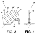
- the cleaning carriage 16 which is shown on a larger scale in FIGS. 3 and 4, preferably consists of a two-part, for example metal support leg 17 and an elastic cleaning lip 18 reaching into the area of the dirt outlet openings 10 of the sliver opening devices 4.
- the support foot 17 also has a portal-like through opening 19, which enables dirt to be removed even if the cleaning carriage 16 positioned on the dirt removal belt 12 and carried along by frictional engagement should be temporarily blocked, for example on the opened swivel cover of an open-end spinning device.
- the cleaning lip 18 has a variety of Cleaning fingers 20, 20 ', 20' 'etc., which are both in terms of their size, shape and / or material can distinguish. That is, the cleaning fingers 20, 20 ', 20 '' etc. are preferably specific to the contours of the components of the Sliver opening devices 4 matched.
- the Cleaning fingers 20, 20 ', 20' 'etc. streak during the Operation at the pollution-prone areas of the Open-end spinning devices along and loosen mechanically any accumulated dirt particles.
- the solved Dirt particles fall onto the dirt removal belt 12 and are from this to (not shown) pneumatic Dirt extraction devices in the area of the machine end frames promoted.
- the cleaning carriage according to the invention 16 the frictionally on the dirt removal belt 12th is stored and the cleaning lip 18 on the particularly pollution-prone areas of the Sliver opening device 4 sweeps along, clearly improved dirt disposal achieved, not least positive in a reduction of the thread breaks occurring affects.
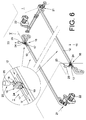
- Figures 5 and 6 show schematically and in perspective View of a mechanical dirt disposal device 11 a Open-end spinning machine 1.
- Such spinning machines have on both sides of the machine, below their open-end spinning devices, not shown in FIGS. 5 and 6, each over an endless Dirt removal belt 12.
- the dirt removal belts 12 are driven and can via reversible electric motors 22 circulate both in direction V and in direction R. There is one on each of the dirt removal belts 12 Cleaning carriage 16 arranged from the rotating Dirt removal belt is taken over friction.
- the dirt removal belts 12 have ends in the area their drives 22 each have a cleaning and Suction device 21 and at the opposite end of the belt each have a starting device 23.
- these starting devices 23 essentially consist of a cleaning slide receiving element 24 and a push piston mechanism 25, which can shift the cleaning sliding receiving element 24 between a receiving and transfer position I and a parking position II.
- a horizontal leg of the cleaning carriage receiving element 24 is positioned just above the dirt removal belt 12.
- the cleaning carriage 12 carried by the dirt removal belt 12 in the direction R moves with its through opening 19 over this horizontal leg and can then be brought into the parking position II by pressurizing the thrust piston gear 25.
Landscapes
- Engineering & Computer Science (AREA)
- Mechanical Engineering (AREA)
- Textile Engineering (AREA)
- Spinning Or Twisting Of Yarns (AREA)
- Preliminary Treatment Of Fibers (AREA)
Applications Claiming Priority (4)
| Application Number | Priority Date | Filing Date | Title |
|---|---|---|---|
| DE19805235 | 1998-02-10 | ||
| DE19805235 | 1998-02-10 | ||
| DE19827610 | 1998-06-20 | ||
| DE19827610A DE19827610B4 (de) | 1998-02-10 | 1998-06-20 | Schmutzentsorgungseinrichtung für eine Offenend-Spinnmaschine |
Publications (3)
| Publication Number | Publication Date |
|---|---|
| EP0936293A2 true EP0936293A2 (fr) | 1999-08-18 |
| EP0936293A3 EP0936293A3 (fr) | 2000-09-27 |
| EP0936293B1 EP0936293B1 (fr) | 2004-04-21 |
Family
ID=26043741
Family Applications (1)
| Application Number | Title | Priority Date | Filing Date |
|---|---|---|---|
| EP99102009A Expired - Lifetime EP0936293B1 (fr) | 1998-02-10 | 1999-02-01 | Appareil pour l'évacuation d'impuretés dans une machine de filature à bout ouvert |
Country Status (4)
| Country | Link |
|---|---|
| US (1) | US6116011A (fr) |
| EP (1) | EP0936293B1 (fr) |
| JP (1) | JPH11279852A (fr) |
| CZ (1) | CZ297619B6 (fr) |
Families Citing this family (3)
| Publication number | Priority date | Publication date | Assignee | Title |
|---|---|---|---|---|
| DE10222012A1 (de) * | 2001-09-20 | 2003-04-17 | Rieter Ingolstadt Spinnerei | Spinnmaschine mit einer Fördereinrichtung |
| DE102014119380A1 (de) * | 2014-12-22 | 2016-06-23 | Rieter Ingolstadt Gmbh | Rotorspinnmaschine mit einer Vielzahl von Arbeitsstellen und einer Absaugeinrichtung |
| DE102016121758A1 (de) * | 2016-11-14 | 2018-05-17 | Saurer Germany Gmbh & Co. Kg | Offenend-Spinnmaschine mit einer Schmutzentsorgungseinrichtung |
Family Cites Families (8)
| Publication number | Priority date | Publication date | Assignee | Title |
|---|---|---|---|---|
| DE2354967C2 (de) * | 1973-11-02 | 1982-07-29 | Fritz 7347 Bad Überkingen Stahlecker | Vorrichtung zum kontinuierlichen Abtransport von an Spinnstellen abgeschiedenen Verunreinigungen |
| DE2356180C2 (de) * | 1973-11-09 | 1984-02-02 | Stahlecker, Fritz, 7347 Bad Überkingen | Vorrichtung zum Abscheiden von Verunreinigungen aus Fasermaterial |
| DE2634770B2 (de) * | 1976-08-03 | 1979-12-13 | Schubert & Salzer Maschinenfabrik Ag, 8070 Ingolstadt | Vorrichtung zum Abführen von Verunreinigungen bei einer OE-Spinnmaschine mit mehreren Spinnstellen |
| DE2658437C2 (de) * | 1976-12-23 | 1986-04-24 | Stahlecker, Fritz, 7347 Bad Überkingen | Offenend-Spinnmaschine mit einer Vielzahl von Spinnaggregaten |
| DE2658752C2 (de) * | 1976-12-24 | 1986-09-18 | Fritz 7347 Bad Überkingen Stahlecker | Offenend-Spinnmaschine mit Mitteln zum Aufnehmen und Abführen abgeschiedener Verunreinigungen |
| DE19640546A1 (de) * | 1996-10-01 | 1998-04-02 | Schlafhorst & Co W | Schmutzentsorgungseinrichtung für eine OE-Spinnmaschine mit einer Vielzahl von nebeneinander angeordneten Spinnstellen |
| DE19652506A1 (de) * | 1996-12-17 | 1998-06-18 | Novibra Gmbh | OE-Spinnmaschine |
| US5901543A (en) * | 1997-11-20 | 1999-05-11 | Anthony; Phillip K. | Independently controlled-brush motor for open-end spinning machine and method |
-
1999
- 1999-01-26 US US09/237,302 patent/US6116011A/en not_active Expired - Fee Related
- 1999-02-01 EP EP99102009A patent/EP0936293B1/fr not_active Expired - Lifetime
- 1999-02-08 CZ CZ0042199A patent/CZ297619B6/cs not_active IP Right Cessation
- 1999-02-10 JP JP11033334A patent/JPH11279852A/ja active Pending
Also Published As
| Publication number | Publication date |
|---|---|
| EP0936293B1 (fr) | 2004-04-21 |
| CZ297619B6 (cs) | 2007-02-14 |
| US6116011A (en) | 2000-09-12 |
| JPH11279852A (ja) | 1999-10-12 |
| EP0936293A3 (fr) | 2000-09-27 |
| CZ42199A3 (cs) | 1999-08-11 |
Similar Documents
| Publication | Publication Date | Title |
|---|---|---|
| DE2356180C2 (de) | Vorrichtung zum Abscheiden von Verunreinigungen aus Fasermaterial | |
| EP0872269B1 (fr) | Procédé et dispositif pour la filtration de fibres d'un courant d'air | |
| DE2504009A1 (de) | Einrichtung zum reinigen rotierender buersten, insbesondere von textilmaschinen | |
| DE19836065A1 (de) | Filterkammer für eine Textilmaschine | |
| DE2634770B2 (de) | Vorrichtung zum Abführen von Verunreinigungen bei einer OE-Spinnmaschine mit mehreren Spinnstellen | |
| DE2242594A1 (de) | Abfallabfuehrvorrichtung fuer eine offen-end-spinnmaschine | |
| DE7801619U1 (de) | Kardiermaschine | |
| DE1939359A1 (de) | Vorrichtung zum Filtrieren von Luft | |
| DE10050974A1 (de) | Abstreifer für eine Walze | |
| EP0356795A2 (fr) | Appareil de nettoyage pour les chapeaux marchants de la machine de cardage | |
| DE2658752A1 (de) | Offenend-spinnmaschine mit mitteln zum aufnehmen und abfuehren abgeschiedener verunreinigungen | |
| EP1213378B1 (fr) | Carde | |
| EP0936293B1 (fr) | Appareil pour l'évacuation d'impuretés dans une machine de filature à bout ouvert | |
| DE19827610B4 (de) | Schmutzentsorgungseinrichtung für eine Offenend-Spinnmaschine | |
| EP1700937B1 (fr) | Dispositif pour enlever de la salissure d'un métier à filer préparatoire comprennant un sytème d'étirage | |
| DE2339880A1 (de) | Pneumatische reinigungsanlage der streckwerke in vorspinn- und spinnmaschinen | |
| DE19755997B4 (de) | Einrichtung zum Sauberhalten einer Textilfasermaterial transportierenden Walze in einer Maschine | |
| EP3321400B1 (fr) | Métier à filer à bout libre avec un dispositif d'élimination de saleté | |
| DE3003827A1 (de) | Einrichtung zur mechanischen reinigung von waessern vermittels von rechen | |
| DE4427771A1 (de) | Textilmaschine mit Filtereinrichtung zum Ausfiltern von Fasern und anderen Verunreinigungen in einer Saugluftanlage | |
| EP0675217A1 (fr) | Dispositif pour nettoyer un rotor tournant dans un boîtier d'une unité de filature à bout libre | |
| DE10207255B4 (de) | Textilmaschine | |
| EP4303349B1 (fr) | Procédé de fonctionnement d'un poste de filage d'un métier à filer et métier à filer | |
| DE4021851A1 (de) | Vorrichtung zum reinigen von unterwindestellen | |
| DE3834452A1 (de) | Reinigungsvorrichtung fuer die wanderdeckel einer karde |
Legal Events
| Date | Code | Title | Description |
|---|---|---|---|
| PUAI | Public reference made under article 153(3) epc to a published international application that has entered the european phase |
Free format text: ORIGINAL CODE: 0009012 |
|
| AK | Designated contracting states |
Kind code of ref document: A2 Designated state(s): CH DE FR IT LI |
|
| AX | Request for extension of the european patent |
Free format text: AL;LT;LV;MK;RO;SI |
|
| PUAL | Search report despatched |
Free format text: ORIGINAL CODE: 0009013 |
|
| AK | Designated contracting states |
Kind code of ref document: A3 Designated state(s): AT BE CH CY DE DK ES FI FR GB GR IE IT LI LU MC NL PT SE |
|
| AX | Request for extension of the european patent |
Free format text: AL;LT;LV;MK;RO;SI |
|
| 17P | Request for examination filed |
Effective date: 20010327 |
|
| AKX | Designation fees paid |
Free format text: CH DE FR IT LI |
|
| 17Q | First examination report despatched |
Effective date: 20021108 |
|
| GRAP | Despatch of communication of intention to grant a patent |
Free format text: ORIGINAL CODE: EPIDOSNIGR1 |
|
| RAP1 | Party data changed (applicant data changed or rights of an application transferred) |
Owner name: SAURER GMBH & CO. KG |
|
| GRAS | Grant fee paid |
Free format text: ORIGINAL CODE: EPIDOSNIGR3 |
|
| GRAA | (expected) grant |
Free format text: ORIGINAL CODE: 0009210 |
|
| AK | Designated contracting states |
Kind code of ref document: B1 Designated state(s): CH DE FR IT LI |
|
| PG25 | Lapsed in a contracting state [announced via postgrant information from national office to epo] |
Ref country code: FR Free format text: LAPSE BECAUSE OF FAILURE TO SUBMIT A TRANSLATION OF THE DESCRIPTION OR TO PAY THE FEE WITHIN THE PRESCRIBED TIME-LIMIT Effective date: 20040421 |
|
| REG | Reference to a national code |
Ref country code: CH Ref legal event code: EP |
|
| REF | Corresponds to: |
Ref document number: 59909213 Country of ref document: DE Date of ref document: 20040527 Kind code of ref document: P |
|
| PLBE | No opposition filed within time limit |
Free format text: ORIGINAL CODE: 0009261 |
|
| STAA | Information on the status of an ep patent application or granted ep patent |
Free format text: STATUS: NO OPPOSITION FILED WITHIN TIME LIMIT |
|
| EN | Fr: translation not filed | ||
| 26N | No opposition filed |
Effective date: 20050124 |
|
| PGFP | Annual fee paid to national office [announced via postgrant information from national office to epo] |
Ref country code: CH Payment date: 20060220 Year of fee payment: 8 |
|
| PG25 | Lapsed in a contracting state [announced via postgrant information from national office to epo] |
Ref country code: LI Free format text: LAPSE BECAUSE OF NON-PAYMENT OF DUE FEES Effective date: 20070228 Ref country code: CH Free format text: LAPSE BECAUSE OF NON-PAYMENT OF DUE FEES Effective date: 20070228 |
|
| REG | Reference to a national code |
Ref country code: CH Ref legal event code: PL |
|
| REG | Reference to a national code |
Ref country code: DE Ref legal event code: R081 Ref document number: 59909213 Country of ref document: DE Owner name: SAURER GERMANY GMBH & CO. KG, DE Free format text: FORMER OWNER: OERLIKON TEXTILE GMBH & CO. KG, 42897 REMSCHEID, DE Effective date: 20130918 |
|
| PGFP | Annual fee paid to national office [announced via postgrant information from national office to epo] |
Ref country code: DE Payment date: 20170227 Year of fee payment: 19 |
|
| PGFP | Annual fee paid to national office [announced via postgrant information from national office to epo] |
Ref country code: IT Payment date: 20170228 Year of fee payment: 19 |
|
| REG | Reference to a national code |
Ref country code: DE Ref legal event code: R119 Ref document number: 59909213 Country of ref document: DE |
|
| PG25 | Lapsed in a contracting state [announced via postgrant information from national office to epo] |
Ref country code: DE Free format text: LAPSE BECAUSE OF NON-PAYMENT OF DUE FEES Effective date: 20180901 |
|
| PG25 | Lapsed in a contracting state [announced via postgrant information from national office to epo] |
Ref country code: IT Free format text: LAPSE BECAUSE OF NON-PAYMENT OF DUE FEES Effective date: 20180201 |